1. Introduction
The International Renewable Energy Agency (IRENA) [
1] suggested that by 2050, globally, around 61% of electricity could be supplied by variable renewable energy (VRE) sources like solar and wind power (WP). Consequently, the electrical power system is quickly migrating the generation mix toward more environmentally friendly generation technologies. Simultaneously, the requirement for balancing the energy supply and demand becomes more and more complex as a result of VRE integration. Coping with the high variability of the future generation mix with incredible high shares of VER, the power system requires developing and enabling sources of flexibility. The reliable operation of the power systems with a high penetration of VRE requires a well-planned and fully used flexibility at all levels of the power system. It includes enabling the maximum flexibility from the power generation to the transmission/distribution system, but also enabling the demand side flexibility; in this process, energy storage plays a very important role.
Power system flexibility is related to the ability of the power system to manage changes. It is, generally speaking, a property of the power system that describes its ability to cope with events that may cause imbalances between supply and demand in different time frames. Flexibility management is one very important mechanism to preserve system reliability at a cost.
The CIGRE working group C5.27, Market Design for Short-Term Flexibility, defines flexibility as “a characteristic of capacity. If we view capacity as the possibility (or option) to either consume or produce electrical energy, then flexibility is the capability to use this capacity freely and to adapt the capacity responding to price signals” [
2]. In the UK, the term flexibility refers to the ability to react to the fluctuating needs of the power system, maintaining the security of supply [
3].
Some of the quantifiable dimensions of flexibility are as follows:
Flexibility power: Refers to the physical capability to deliver flexible power, e.g., the size of the flexible active or reactive load, expressed in MW for active power flexibility or presented on MVAr for reactive power flexibility.
Flexibility response time: It is defined as the time until the flexibility (for instance, flexible power) can be delivered, e.g., related to the start-up time of a power plant, expressed in seconds–minutes–hours–days–years. Power electronic-based technologies are very effective in terms of the very short flexibility time response enabled on them. However, it is important to consider the speed response of the primary energy source, e.g., extremely short for ultra-capacitors and relatively small for some types of battery energy storage systems.
Flexibility speed: The rate at which the flexibility can be delivered. It is typically defined as a rate of change where the flexibility is expressed in terms of the changes over time. For instance, the emergency ramp rate of an HVDC, which is expressed in terms of the active power change over time (MW/s).
Flexibility duration: Defines how long flexibility can be provided. It is expressed in terms of time, e.g., the time span for the overload rating of a component, expressed in seconds–minutes–hours, etc.
Flexibility energy: It is the total energy provided by the flexibility; it can be obtained considering the flexibility power and flexibility duration dimensions. As an energy, the typical unit used to represent it is MWh.
Flexibility recovery period: It is defined as the time interval that is needed in order to provide flexibility after it has been fully utilised, e.g., the time required to reach full state-of-charge (SoC) charge in an empty energy storage system (ESS) after providing it flexibility; it is expressed in units of time, varies from seconds, minutes, hours, or more, depending on the technology used to provide the flexibility.
More details about more flexibility metrics can be found in [
2].
Power system flexibility studies have been taking more relevance in recent years because of the high integration of VER. As a result, several methodologies in the scientific literature have studied for the implication of integrating flexible sources to enhance power balancing and cope with the high penetration of VER. For instance, numerous research publications have focussed on creating models for power system flexibility assessment proposes. These models are based on mathematical approaches defining the power system operation limits [
4,
5], based on indexes [
6,
7,
8], such as the operational flexibility index, and on charts and graphic tools [
9,
10]. Furthermore, several methodologies have been proposed to study the variability of the VER using optimisation approaches [
11,
12,
13] or using the analytical model of the power reserves [
14,
15]. The variability of the load that VERs cannot cover has been addressed using a recently created service named the flexible ramp product [
16,
17,
18]. Moreover, different methodologies have been proposed to study the flexibility requisites considering several aspects, such as medium- and long-term planning, dispatch, and unit commitment [
19,
20,
21]. Lately, numerous studies have been carried out considering the electrical market design in order to assess how it influences power system flexibility [
22,
23,
24,
25,
26]. A detailed review of the methodologies applied to assess the power system flexibility is presented in [
27].
In this paper, the flexibility is fully enabled considering the increased use of digitalisation, which helps to maintain balance on the system efficiently. It considers the extensive implementation of information and communication technologies and solutions as enablers of the power system flexibility. In addition, this scientific paper considers integration as a key element enabling flexibility.
This paper proposes and demonstrates a single layer control system for coordinating the operation of battery energy storage system (BESS) and wind power plants via multi-terminal high voltage direct current (HVDC). The proposed single-layer coordinating controller is a closed-loop controller that uses wide-area measurements in the system to coordinate several transmission/distribution and energy storage assets. The proposed coordinated controller is a single layer controller on top of the power converter-based technologies. Specifically, the coordinated controller uses the capabilities of the distributed-BESS assets to store electricity when the logic function of the proposed controller is satistied.
Section 2 proposed a single layer coordinated controller; it is intended to coordinate the active power injection/abortion of distributed-BESS installed in an AC interconnected multi-machine power system. One very important element of the controller is reaching the coordinated charging/discharging of the BESSs according to the interactions in the multi-terminal DC system where offshore wind power plants inject a variable volume of active power.
Section 3 is dedicated to implementing the proposed coordinated controller and discussing the numerical simulation results using a customised version of the IEEE 14-bus, including novel power electronic converter technologies. Finally, the main conclusions and findings are summarised in
Section 4.
2. Coordinated Distributed-BESS and Wind Power Plant
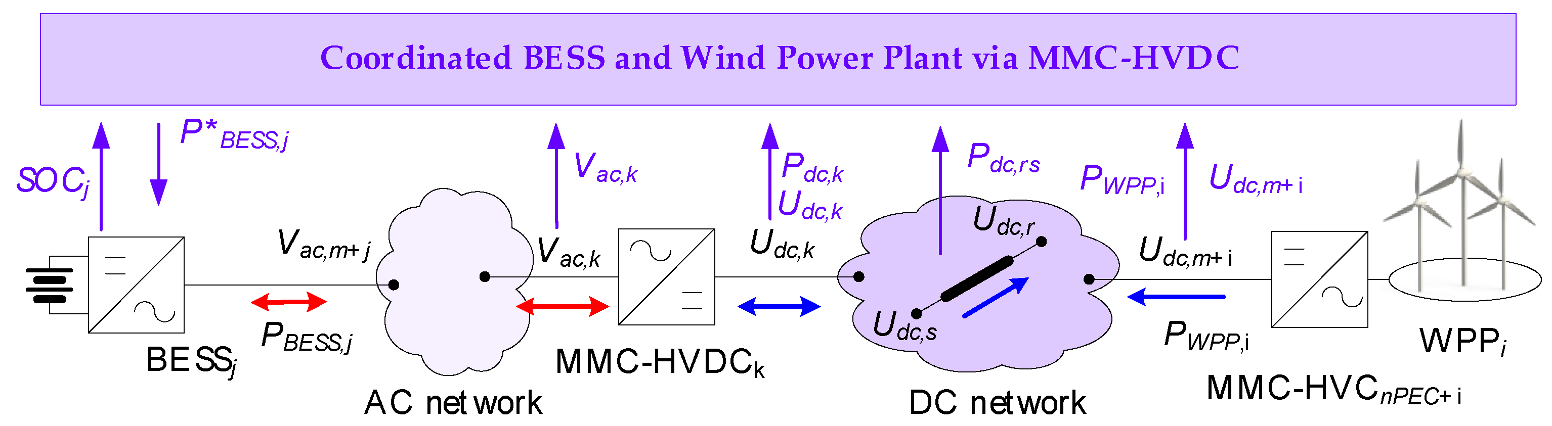
Reaching an acceptable reliability level of operation in a power system with a massive penetration of VRE requires taking advantage of all of the possible flexibilities available in the system. Power electronic converters provide an interface with a very fast response; as a consequence, when combined with appropriate energy technology, the result will be a very useful level of flexibility. In this paper, a coordinated BESS and wind power plant is proposed. The proposed controller is intended to coordinate the active power injection/abortion of the distributed-BESS installed in an AC interconnected, multi-machine power system. The key element is coordinating the charging/discharging behaviour of the BESS according to the interactions in the multi-terminal DC system, where the offshore wind power plant injects a variable volume of active power. The general scheme of the main components of the coordinated BESS and wind power plants control is presented in
Figure 1.
The proposed coordinated controller is a single layer controller on the top of the power converter-based technologies. Specifically, the coordinated controller uses the capabilities of the distributed-BESS assets to store electricity when the logic function of the proposed controller is satisfied. For instance, the logic function can be implemented in order to allow for the charge of the BESS where the offshore wind power production is such that it surpasses a specific threshold, and then the BESS is used to compensate for the active power reduction of the offshore wind power plants when there are low wind speeds. However, many other logic functions can easily be implemented (as illustrated in the next section). The charge and discharge of the BESS asset are managed considering two control actions. The coordinated controller takes actions at the modular multilevel converter-HVDC (MMC-HVDC) stations located in the AC/DC interface; it is implemented by taking advantage of the local controllers at each one of the MMC-HVDC stations and the voltage−power (
Udc-
Pdc) control (see
Figure 2).
The charger controller is a local controller that belongs to each one of the distributed BESSs, and it is intended to keep the SoC inside the operational limits (SoCmin,j ≤ SoCj ≤ SoCmax,j, j = 1, …, nbess). The coordinated controller uses digital communication to monitor the SoC of all BESS assets during the time it produces active power references to control the active power injection/consumption. It is based on a coordinated logic between the offshore wind power plants and the multi-terminal DC system, using the MMC-HVDC stations to deliver the required power flow.
A distributed-BESS (BESSj) will charge and discharge based on the reference signal provided by the coordinated controller (P*BESS,j); the local SoC controller will then check if the asset is able to deliver the requested reference based on the actual SoC, delivering the requested reference, if the asset is not able to fulfil the requested reference; and then the coordinated controller will use the next available distributed-BESS based on a priority table created based on the SoC.
The core of the proposed coordinated controller is a logic function that defines the charging and discharging action of the distributed-BESS assets. Many logic functions can be implemented depending on the agreements between the different system operators. For instance, the logic function can be implemented to cope with offshore wind power production variability.
When the total offshore wind power production (PWPPT = PWPP1 +… +PWWPnwf < PTref) is below the threshold, the coordinated controller will provide reference signals to the charged BESS (SoCj > SoCmin,j), the order of discharge starts from the asset with the larger SoC continuing to the less charged BESS. In the opposite situation, the BESS is charged when PWPPT > PTref.
The proposed controller is able to implement any control logic related to AC or DC measurements and AC, DC, or even AC/DC objectives; the only limit is that imposed by the electrical circuit and the power electronic converters. The real implementation of the proposed coordinated controller is very simple. The digitalisation of the power system allows for the integration of digital technologies that offer a very low latency. The time scale of the action taken is in several seconds up to a minute. As a consequence, the modern digital communication technologies (5G wireless and optic fibre) offer almost no time delay on transmitting the measurements or sending back the control commands.
The appropriate infrastructure for the control is already available in many commercially available power converters. The very well know IEC 61850 standard enables substation automation by standardising communication between devices from different manufacturers. The implementation of the IEC 61850 GOOSE (Generic Object-Oriented Substation Event) and the Manufacturing Message Specification (MMS) allows for a simple way to implement control actions in power electronic converters and so many other technologies. There are very well documented experiences regarding the use of IEC TR 61850-90-7 and UL 1741 standards in the development of the control of the so-called smart PV inverters [
28].
2.1. Voltage Control in DC Transmission Systems
Several topologies are available regarding the implementation of PWM (pulse-width modulation) power converter stations for DC transmission system applications: self-commutated, voltage-source AC/DC two-level converter, and a modular multilevel converter (MMC). The use of MMCs is the power electronic converter (PEC) topology of choice for a voltage source converter (VSC) high voltage direct current DC (VSC-HVDC) transmission system. Several technical and economic reasons make them very attractive for VSC-HVDC [
29], including the very high efficiency (reducing losses through voltage levels to build an output waveform) and technical features, such as a very fine and compact power control and back start functionalities.
The modelling of power converter stations based on MMC-HVDC systems requires special attention to the details. In this paper, the implementated MMC-HVDC station is based on a full-bridge configuration (also called H-bridge), as presented in
Figure 3 and
Figure 4 [
30].
Steady-state conditions of the MMC-HVDC station are controlled using the modulation index. The line−line AC voltage at the node
k (rms value,
Vac,k =
Vac,k,d +
jVac,k,q) and DC voltage (
Udc,k) are related by the following:
where
md,k and
mq,k are the real and imaginary part of the modulation index (
mk), respectively.
Several control modes are possible at the MMC-HVDC station; for simplicity in this scientific paper, three main control technologies are presented and used for illustrative purposes in the next section.
2.1.1. Control Mode Udc-Qac
This control mode allows for controlling the voltage on the DC side (
Udc) of the MMC-HVDC station, and the time to control the reactive power (
Qac) is on the AC side. This control method is used for many applications, including FACTS like STATACOM, shunt-converter in the UPFC configuration, type 3 wind turbine generators (grid-side converter of the doubly-fed induction generator), and MMC-VDC-HVDC systems. More information about this control model can be found in [
31,
32].
2.1.2. Control Mode Pac-Qac
This control mode is specifically used when the control quantities at the MMC-HVDC stations are the active (
Pac) and (
Qac) reactive power at the AC side. This controller is able to replicate the operational PQ mode used to represent a synchronous generator in steady-state conditions. More information about this control model can be found in [
33,
34].
2.1.3. Control Mode Udc-Pdc-Droop
It is possible to set the MMC stations using a
Udc-
Pdc characteristic. The typical control rule is the use of a proportional control between the voltage and power. The DC-voltage dependent P-droop allows for defining the active power setpoint that follows the following equation:
where
Pdc,ref is the reference of
Pdc,ref used at the MMC-HVDC station,
Pdc,set is the active power setpoint,
Udc is the actual voltage at the DC side of the MMC-HVDC station,
Udc,set is the DC voltage setpoint, and
ρdc is the proportionality factor defining the DC-voltage dependent
Pdc-droop.
2.2. Distributed Battery Energy Storage Systems
The distributed-BESS consists of three components (see
Figure 5): (i) an energy storage package, a set of batteries with an appropriate connection to provide; (ii) a power electronic converter model (inverter/rectifier); and (iii) several control loops installed to allow for the proper operation of the energy storage system [
35,
36].
An MMC-VSC is used as the interface between the energy storage pack and the AC grid. As this scientific paper is focused on the steady-state of the power system, the performance of the PWM-converter is modelled using an equivalent to the fundamental frequency. The line−line AC voltage (RMS value
Vac =
Vac,d +
jVac,q) and DC voltage (
Udc) are related by the following:
where
md and
mq are the real and imaginary part of the modulation index, respectively.
3. Implementation and Results
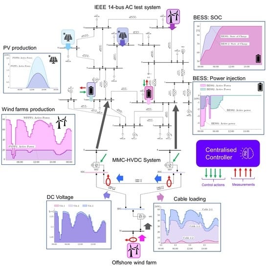
In this section, the well-known IEEE 14 bus test system is used to illustrate an implementation of the proposed coordinated control. The IEEE 14 bus test system is a representative example of a reduced area of the American Electric Power System (in the Midwestern area of the United States of America) as of February 1962. It consists of five synchronous machines, three of which are synchronous compensators (SC) used only for reactive power production and voltage improvement. The IEEE 14 bus system is used to represent the AC interconnected multimachine system (see
Figure 6). It has a total of 11 loads for a total load of 259 MW and 81.3 Mvar. The original data of the test system are publicly available at:
https://labs.ece.uw.edu/pstca/pf14/pg_tca14bus.htm (accessed on 5 May 2021).
The IEEE 14 bus test system has been customised in this paper in order to integrate new technologies. The following two wind power plants are added: onshore wind farm (WPP1, bus 14, 2 × Gamesa SG10) and offshore wind farm (WPP2, bus 15, 2 × Gamesa SG10). A multi-terminal MMC-HVDC system (three terminals—
Figure 7) is used to connect the WPP2 to the IEEE 14 bus system (buses 4 and 5). Two photovoltaic power plants (PVPP1 and PVPP2, bus 11 and 12, respectively), an electric vehicle (PHEV, bus 9), and two distributed-BESSs (bus 4 and 5, 30 MWh each) are added to the network. More details of the customised network can be found in [
37].
The proposed coordinated controller is illustrated considering a representative period of 24-h (1-min resolution).
Figure 8 shows the load profile of the 11 loads connected in the AC test system, and
Figure 9 and
Figure 10 show the power production of the PV power plants and wind power plants.
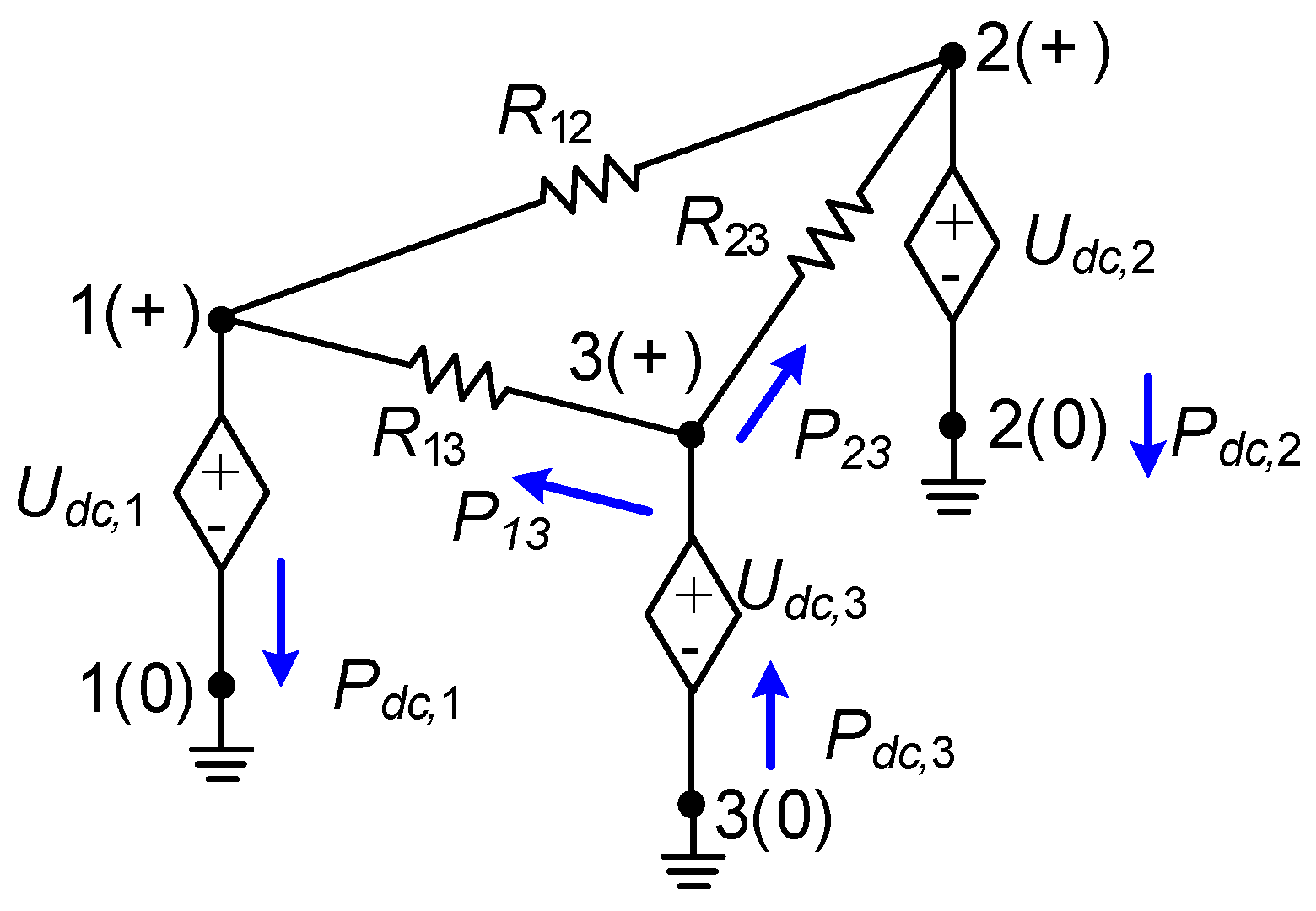
In this section, coordinated control has been implemented in a very challenging way. The multi-terminal MMC-HVDC system uses three undersea cables (delta connection) to transport the power production of the offshore wind power plant (
PWPP2), as presented in
Figure 10. The power production of the offshore wind farm has periods reaching the rated power, but there are also periods where the power production is very reduced (~7MA @2:57am). As the DC-undersea cables are connected to a monopolar MMC-converter configuration using a delta connection (the most simple and basic configuration), the power flow in the multi-terminal DC system is easily controlled by the DC terminal voltage (see
Figure 11).
Cable 1–2 is basically an interconnector between the two onshore connection points, and it can be used to modulate the power injection/absorption at AC buses 4 and 5, where DC node 3 is the key component as WPP1 is injecting the power (Pdc,3 = P13 + P23). In this paper, the power flow of cable 1–3 and cable 2–3 are monitored.
Now, to illustrate the proposed coordinated controller, the active power injection/consumption of the two BESSs are used as the main control variable (PBESS1 and PBESS2), and their SoCs are monitored (SoC1 and SoC2). The local state-of-charge controller is enabled to fulfill the following: SoCmin = 10% ≤ SoCk ≤ SoCmax = 90% (k = 1, 2). The DC power flows in cable 1–2, and cable 2–3 is taken as the decision variable. If P12 > P*12, BESS1 is charged (otherwise, discharged), and if P23 > P*23, BESS2 is charged (otherwise, discharged). The charging process of each distributed asset is controlled based on the SoC and active power injection/consumption. If SoCk ≥ SoCmax, stop charging. Charge if SoCmin ≤ SoCk ≤ SoCmax, then the active power is discriminated between the nominal storing active power, power to start storing, and power to store at full power.
The multi-terminal MMC-HVDC stations are equipped with a local station controller, MMC-HVCD1 and MMC-HVDC2 are equipped with Vdc-Qac controller, where the reactive power production of the converter is adjusted to zero (Qac = 0); on the other hand, Udc1 and Udc2 are adjusted to 1.05 and 0.99 pu, respectively.
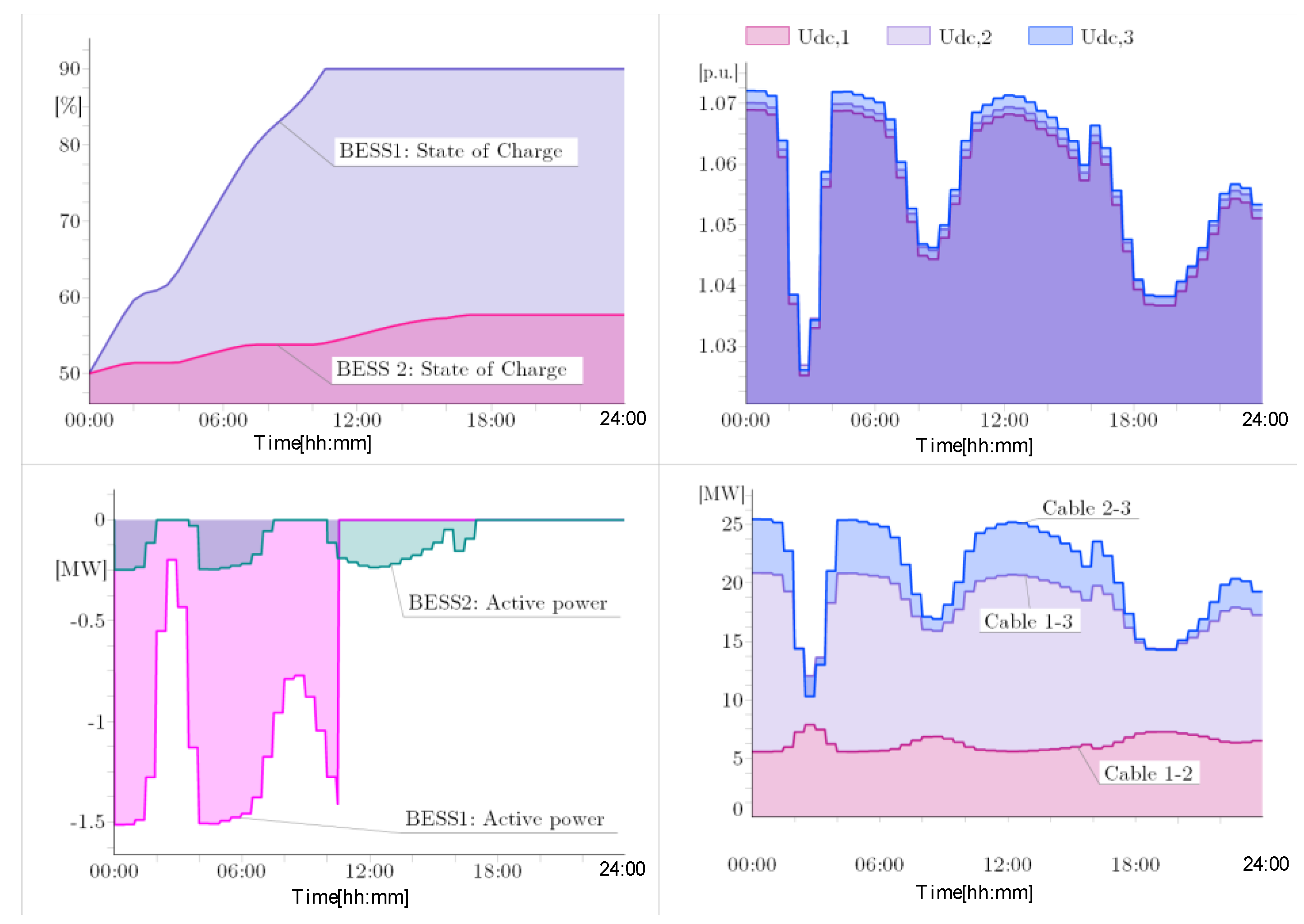
Initially, a quasi-dynamic simulation for a 24-h (1-min) resolution is performed to demonstrate the suitability of the proposed coordinated controller. The simulation results considering MMC-HVCD
1 and MMC-HVDC
2 equipped with
Vdc-
Qac controllers are shown in
Figure 12. The proposed controller monitors the power flow at cable 1–3 (
P13) and cable 2–3 (
P23); when the power is above 15 MW, the correspondent BESS starts to charge (
SoC0 = 50%), it is clear in
Figure 11 that at 02:37 a.m., the power flows in those cables is reduced at BESS 2, stops charging for a period, and then continues; the SoC of both BESSs arrives to
SoCmax = 90% is the power production in the offshore wind farm and the coordinated controller allows it, then the BESS reaches the maximum SoC and the centralised controller stops the power absorption. This preliminary simulation demonstrates the suitability of the proposed controller to fulfil a coordinated operation between the distributed BESS and offshore wind farm by the use of a multi-terminal MMC-HVDC systems.
Figure 13 and
Figure 14 show the performance of the proposed controller considering low wind speed and mid-wind speed, respectively; as the wind speed is reduced at the wind power plants, the active power production is reduced. However, the coordinated controller is able to charge the distributed BESS considering the control logic based on the cable DC power flow. As the wind speed is low, the power production is reduced, but the controller is able to charge the BESS. The time to reach the
SOCmax = 90% is increased, but the controller is able to fulfil the objective.
As the controller has been successfully tested and has demonstrated its suitability of the proposed approach, the final step is to assess the flexibility. The instantaneous active power flexibility of the whole AC−DC system is assessed.
Figure 15 shows the balancing power required from the generator G1 without the proposed controller, and this time series is used as a base case to calculate the instantaneous flexibility power. The flexibility power, in this case, is obtained by the effective coordinated control of distributed-BESS and offshore wind farm via the multi-terminal MMC-HVDC system.
Figure 16,
Figure 17 and
Figure 18 show the time series plots of the balancing power required from the generator G1, considering three wind speed (high, mid, and low) scenarios at the offshore wind power plant and enabling the proposed controller.
Increasing the wind speed at the wind power plants increases the power generation, but the balancing power is also increased if the extra power is not appropriately diverted to the distributed-BESS by the proposed coordinated controller. However, the available instantaneous flexibility is strongly correlated with the changing pattern of the distributed assets (see
Figure 19). It is, generally speaking, a property of the power system that describes its ability to cope with events that may cause imbalances between supply and demand at different time frames.
4. Conclusions
Modern power systems are facing several challenges; one of them is the massive penetration of variable renewable energy (VRE), especially for weather dependent technologies like wind and photovoltaic power. The growing volume of VRE increases the need to respond to the fluctuating needs of the power system, maintaining the security of the supply. The flexibility, generally speaking, refers to the property of the power system that describes its ability to cope with events that may cause imbalances between the supply and demand at different time frames. In this paper, a single layer coordinating controller is proposed and demonstrated. The single proposed layer coordinating controller is a closed-loop controller that uses wide-area measurements in the system to coordinate several transmission/distribution and energy storage assets. The controller uses a logic function to coordinate the steady-state operation of BESSs and wind power plants via a multi-terminal high voltage direct current (HVDC).
The single proposed layer coordinating controller is designed to build on the top of the local controller installed at the local assets, and uses low latency communication to implement the monitoring and control actions. One positive aspect of the proposed controller is that it has straightforward implementation. Digital communication is used for monitoring and control purposes; a centralised computer running the proposed algorithm is responsible for defining the control signals. As modern power converters are enabled to receive reference signals, the implementation of the proposed approach will not require drastic modifications at the BESSs, HVDC, or wind farm power converters. When compared with similar controllers, the proposed controller takes advantage of the local control functions enabled at the installed power converters; it reduces the computational burden of implementation. However, using the enabled control functions limits the flexibility of the approach, and exploring more complex and less traditional control strategies is not currently possible.
The proposed controller has been demonstrated using numerical simulations over a 24-h (1-min resolution) period using a customised version of the IEEE 14-bus test system, including a multi-terminal MMC-HVDC system. The controller has been implemented, and the capacity of fulfilling the defined control logic has been demonstrated. The instantaneous flexibility power has been used to assess the performance of the proposed controller. The results of the numerical simulations have demonstrated the suitability of the proposed coordinated controller to provide flexibility and decreasing requirements for balancing power.


 ,
, 


