Article

Assessing Potential Thermo-Mechanical Impacts on Caprock Due to CO2 Injection—A Case Study from Northern Lights CCS

by
Nicholas Thompson
1,*,
Jamie Stuart Andrews
2 and
Tore Ingvald Bjørnarå
3
1
Equinor ASA, 7053 Trondheim, Norway
2
Equinor ASA, 4035 Stavanger, Norway
3
Norges Geotekniske Institutt, 0806 Oslo, Norway
*
Author to whom correspondence should be addressed.
Submission received: 17 June 2021 / Revised: 5 August 2021 / Accepted: 11 August 2021 / Published: 17 August 2021
(This article belongs to the Special Issue Geomechanics Applied to Carbon Capture and Storage)

Abstract

:
Due to significant temperature differences between the injected medium and in situ formation, injection of CO2 (as with water or other cold fluids) at depth induces thermal changes that must be accounted for a complete understanding of the mechanical integrity of the injection/storage system. Based on evaluations for the Northern Lights Carbon Capture and Storage (CCS) project, we focus on thermal effects induced on the caprock via conduction from cooling in the storage sands below. We investigate, using both analytical and numerical approaches, how undrained effects within the low permeability caprock can lead to volumetric contraction differences between the rock framework and the pore fluid which induce both stress and pore pressure changes that must be properly quantified. We show that such undrained effects, while inducing a more complicated response in the stress changes in the caprock, do not necessarily lead to unfavourable tensile conditions, and may, in fact, lead to increases in effective stress. These observations build confidence in the integrity of the caprock/seal system. We also show, through conservative assumptions, that pressure communication between the caprock and storage sands may lead to a localised negative effective stress condition, challenging stability of the base caprock, which will be mitigated for in field development planning.

1. Introduction

The Northern Lights full-scale demonstration project [1] represents a significant step forward in developing an offshore Carbon Capture and Storage (CCS) industry offshore Norway. The project consists of shipping, temporary storage, pipeline transport and permanent geological storage via dedicated injection wells and is part of the larger Longship project [2], which includes onshore capture at one or two industrial facilities. The aim of the flexible ship transport solution is to eventually allow for low-cost, industrial decarbonisation at scale.
The NO 31/5–7 (Eos) well was drilled in 2019–2020 to prove (A) committable storage and (B) storage integrity. Data collection was key, and as such extensive logging, coring, production testing and in situ stress testing (extended leak-off (XLOT)) were employed. The storage complex is defined as the Lower Jurassic Dunlin Group Johansen and Cook Fms. with the Drake shale acting as the primary seal. During Phase 1 of the Northern Lights project, up to 1.5 Mt/yr liquefied CO2 will be injected for 25 years into the Johansen Fm., where the overlying Cook formation will serve as storage through eventual upwards migration away from the injection well(s).
As downhole injection temperatures of the CO2 (~25 °C) are significantly lower than the initial formation in situ (~105 °C), the geomechanical evaluation for Northern Lights included a thorough investigation of potential thermal effects from CO2 injection. Within the reservoir, which is not discussed in detail in this article, thermal effects investigated include evaluation of stress reduction and the evolution of in-fill drilling windows [3], thermal fracturing [4], fault reactivation potential [5], and impact on sand production potential and lower completion design. Here, however, we focus on the thermally-induced stress changes occurring within the Drake seal/caprock unit. Several other authors have investigated this in connection with CO2 injection [6,7,8,9,10,11] under various circumstances, each concluding that thermal effects may play an important role in maintaining caprock integrity. However, one difference here is that the investigation is taken further to include the effects induced by thermal changes not just on the bulk caprock material, but on the pore fluid itself using both analytical and numerical methods. Differences in the volumetric contraction response between the bulk rock, grains and the pore fluid(s) are investigated, as are subsequent pore pressure and stress changes and the net effect on caprock stability. Both the undrained and drained response effects on caprock integrity are considered. We find that while these thermally-induced effects may penetrate quite far within the caprock, as long as fluid pressures in the reservoir storage units are not in contact with the caprock (e.g., through leaky faults or induced fractures), no detrimental effect on caprock stability are predicted. However, in the conservative scenario where virgin and/or elevated reservoir pressures are assumed to come in contact with reduced effective stresses within the caprock, tensile and/or shear failure conditions at the base caprock may occur. Given the planned development scenario of CO2 injection some vertical distance below the caprock, an interval characterised by one or several sealing shale units, this builds confidence that the caprock will retain its integrity despite significant thermal change conditions.

2. Cooling of Caprock

Reference is made to the work in [12], where an introduction to the Northern Lights geology is given; the work in [13], which discusses reservoir geology specifically; as well as in [14], where a more detailed description of the caprock geology and in-stress regime is given. Note also that the data from the Eos well have been made publicly available [15]. The thickness of the relevant storage and seal units encountered by the Eos well is (from shallowest to deepest):
  • Drake shale (primary seal)—127 m
  • Cook sand—(primary storage)—57 m
  • Burton shale—7 m
  • Johansen sand (primary storage)—116 m
The Drake shale is split into two intervals, the shallower Drake 2 Fm. and the deeper Drake 1 Fm. The Drake 2 Fm is not considered as part of the primary seal. The Drake 1 Fm. contains variable mineralogy, primarily within a 26 m thick interval in its centre, termed the Intra Drake. This Intra Drake belongs stratigraphically to the Drake 1 Fm. and is characterised by high clay content (~75% illite/smectite/kaolinite) and interpretable as regional seismic horizon. The Drake Fm. 1, being divided by the Intra Drake, is termed Upper and Lower Drake 1 Fms. (above and below the Intra Drake, respectively) to denote the split. The mineralogy and heterogeneity of the Drake shale is discussed in detail in [14], but for the purpose of this study the Drake is simplified as a homogenous caprock of constant properties.
The Cook and Johansen sands are each divided into 4 units; only the deeper Johansen (Johansen 1 and 2) will be completed and receive injected CO2 during Phase 1 of the Northern Lights project. There is therefore 114 m of sand (Cook + Upper Johansen) and shale (Burton) overlying the injection interval and separating the target sands from the caprock seal. In this work, we assume a very conservative scenario where injection leads to maximum cooling of the Cook formation directly underlying the Drake caprock. This is an unlikely scenario, but the objective is to confirm the robustness of the caprock seal to thermo-mechanical aspects from potential cooling.
Assuming this scenario, potential propagation of cooling into the Drake caprock (via conduction) is shown in Figure 1, estimated through the thermal diffusivity coefficient ( α D , not to be confused with Biot coefficient ( α , see below)):
α D = κ ρ c p ,
where κ (conductivity) = 1.44 J/K/m/s, ρ (density) = 2563 kg/m3, and c p (heat capacity) = 837 J/Kg/K. This gives a thermal diffusivity coefficient of 6.7 × 10⁻⁷ m2/s (21.2 m2/yr).
Figure 1 shows that, for a case of Δ T = −80 °C, cooling from conductive heat transfer may penetrate, to some degree, as high as the lower section of Drake 2 over the course of 25 years. Again, this estimation conservatively assumes the Cook sand is directly exposed to cooled CO2 at 25 °C. An additional assumption is that input properties in Equation (1) are representative and constant over the entire Drake Fm. interval.

3. Mechanism Overview

Cooling of the caprock from conductive heat transfer will necessarily result in stress changes in the caprock. As shown above, the thermal diffusivity is sufficiently large that substantial regions of the caprock can, given conservative assumptions, potentially be cooled during the operational lifetime of the CCS project. This cooling will induce contraction in both the bulk rock, the solid constituents of the rock (grains) and the fluid (water) phase. As the volumetric contraction of the bulk rock is often smaller than the summed contraction of the fluid and grains, this can result in a reduction in the pore pressure in the cooled caprock—at least transiently in tight, nano-Darcy rock. This will also influence the total stress in the caprock, thus leading to a complex scenario when evaluating changes in the effective stress in the cooled caprock. In the case that the contraction of the bulk rock is larger than that of the pore fluid, increases in pore pressure can occur, leading to reduced effective stress. This is shown schematically in Figure 2.
These effects are investigated analytically and numerically in this work where we focus on two primary damage mechanisms:
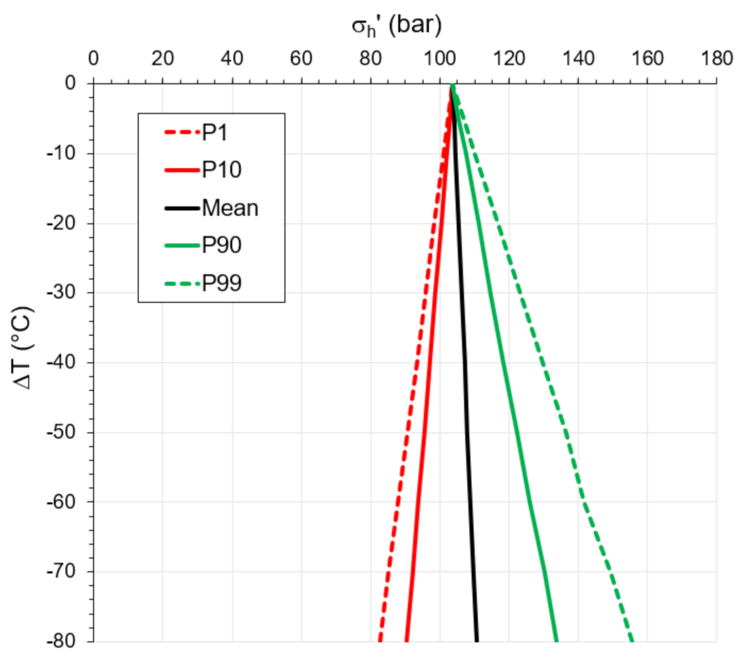
  • “Internal” integrity loss (also termed auto-/self-fracturing) through the development of negative effective stress changes in caprock. Both undrained (changes in temperature and fluid pressure) and drained (changes in temperature) caprock behaviours are considered. For maintained integrity of the caprock, the in situ minimum effective stress, σ h , should not reduce to 0 (or below) to avoid the development of tensile stresses in the caprock.
  • “External” integrity loss (hydraulic fracturing, tensile failure) whereby virgin pore pressure at top reservoir (Cook) is sufficient to overcome the thermally reduced minimum stress in the cooled Drake caprock. The assumption is that there is sufficient natural heterogeneity along the large caprock surface that there are many potential natural fracture initiation points which can act as “weak points” where any pressures in the Cook that exceed the minimum principal stress in the overlying Drake can theoretically lead to growth of fractures in the caprock.
As shown later, an additional assumption for the analytical work is the undrained response in the low shale permeability (no pore pressure diffusion). This is supported by laboratory measurement of Intra Drake core where in situ permeabilities of ~1 nD were found. For completeness, drained behaviour response is also considered in the analytical work even though we note that the thermal diffusivity coefficient (21.2 m2/yr) is significantly larger than the pressure diffusivity coefficient ( C D ):
C D = k η f 1 S = 0.85   m 2 / yr ,
where S (storage term) here is given by
S = ϕ K f + α ϕ K S ,
when this is estimated using base case mechanical and petrophysical properties for the shale (Biot poroelastic coefficient [ α ] is assumed to be 0.93 (based on log-derived elastic properties, Table 1), fluid viscosity [ η f ] assumed to be 0.4 cp, permeability [ k ] assumed to be 1 nD; otherwise, refer to Table 1 below for explanation of terms and values used). We see that thermal conductivity is at least an order of magnitude faster than pressure diffusivity in the caprock and this confirms that undrained behaviour during cooling can be assumed initially for this tight caprock formation.

4. Analytical Estimations

4.1. Property Assumptions

A critical input for this investigation is the framework stiffness ( E f r ) of the Drake shale material. Laboratory testing is ongoing, but while these results are not finalised, this was estimated via the empirical correlation presented by Horsrud [16] which is a correlation based specifically on shales from the Norwegian Continental Shelf (NCS):
E f r = 0.076 304.8 Δ t p 3.23 ,
where Δ t p is the P-wave travel time from sonic logging (ms/ft). Results are shown in Figure 3.
We note that shales will typically exhibit mechanical anisotropy, and models that treat the TIV symmetry (transverse isotropy with a vertical axis of symmetry) correctly should really be used to estimate these properties and in the modelling work. The E f r from the Horsrud correlation is based on measurements performed on vertical cores (i.e., vertical E f r ) and the compressional sonic velocity in the vertical/axial direction. In the analytical model presented below, we assume isotropic mechanical properties for the shale, and this is thus a simplification. However, one way to partially account for the anisotropy would be to use the E f r in the horizontal plane and not in the vertical direction—the former typically being larger than the latter in shales.
Input parameter assumptions are shown in Table 1. For the analytical models (presented in the next section), a Monte Carlo uncertainty analysis (10,000 realisations) was performed to estimate changes in minimum stress and pore pressure due to cooling given reasonable ranges in some of the input parameters.

4.2. Internal Integrity Loss

The initial total minimum horizontal stress ( σ h ,   i n i ) at base Drake is estimated to be 368.6 bar and with an initial pore pressure ( P p ,   i n i ) of 265 bar. This gives an initial effective minimum horizontal stress ( σ h ,   i n i ) of 103.6 bar (assume Biot coefficient of 1.0 for initial in-situ stress conditions). More information on the stress characterisation and stress measurements made can be found in [14].
An analytical tool has been developed to estimate the pressure and stress changes in the caprock that develop due to cooling from an underlying CO2-flooded reservoir. This is a simple model where several simplifying approximations are made, but it has the advantage that it enables Monte Carlo simulation on the influence of the various parameters to establish sensitivities to these for the caprock integrity given the level of uncertainty in the input data. The convention used in this work is that stress changes are positive in compression.
In the following we assume an isotropic elastic material—even though this is generally not the case for layered materials such as shales. Pore pressure change ( Δ P p ) due to thermal changes is first estimated given the relationship below:
Δ P p = α S Δ ε V + 1 S Δ ζ + ϕ β f + α ϕ β S v o l S Δ T ,
Equation (5) is the poroelastic constitutive equation modified to include effects caused by differential expansion/contraction between the fluid and solid grains. Explanations for several of these parameters are found in Table 1 and/or in equations below.
If undrained behaviour is assumed, the fluid strain parameter ( ζ ) → 0 and this simplifies Equation (5) to
Δ P p = α S Δ ε V + ϕ β f + α ϕ β S v o l S Δ T ,
Assuming an isotropic material and uniaxial strain conditions only, such that the change in volumetric strain ( Δ ε V ) is determined only by the vertical strain change ( Δ ε z ), (i.e., horizontal strain Δ ε h = 0) gives the following for the bulk rock strain changes:
Δ ε V = Δ ε z = 1 E f r Δ σ z 2 ν f r Δ σ h β T Δ T ,
Δ ε h = 1 E f r Δ σ h 1 ν f r ν f r Δ σ z β T Δ T = 0 ,
such that the change in effective horizontal stress ( Δ σ h ) then is given by
Δ σ h = v f r 1 ν f r Δ σ z + E f r β T Δ T 1 v f r ,
Due to the uniaxial strain assumption, where no stress arching is assumed, the change in effective vertical stress ( Δ σ z ) is therefore given by the pore pressure change ( Δ P p ) corrected by the poroelastic contribution:
Δ σ z = α Δ P p ,
such that the change in total horizontal stress ( Δ σ h ) can now be expressed by
Δ σ h = 1 2 ν f r 1 ν f r α Δ P p + E f r β T Δ T 1 ν f r ,
Revisiting Equation (7) and replacing Δ σ h with Equation (9) gives
Δ ε V = Δ ε z = 1 E f r Δ σ z 2 ν f r ν f r 1 ν f r Δ σ z + E f r β T Δ T 1 ν f r β T Δ T ,
and by rearranging and simplifying using Equation (10):
Δ ε V = 1 E f r 1 2 ν f r 1 + ν f r 1 ν f r Δ σ z β T 1 + ν f r 1 ν f r Δ T = α H m Δ P p β T 1 + ν f r 1 ν f r Δ T ,
where the uniaxial compaction coefficient ( H m ) term is given by
H m = 1 2 ν f r 1 + ν f r E f r 1 ν f r ,
Using the above, we find that Equation (6) then becomes
Δ P p = α S α H m Δ P p β T 1 + ν f r 1 ν f r Δ T + ϕ β f + α ϕ β S v o l S Δ T ,
and simplifying further,
Δ P p 1 + α 2 S H m = Δ T α β T 1 + ν f r S 1 ν f r + ϕ β f + α ϕ β S v o l S ,
Thus, the pore pressure change due to thermal changes in an undrained caprock medium with assumed uniaxial strain conditions can be expressed most simply as
Δ P p = Δ T 1 + ν f r 1 ν f r α β T ϕ β f + α ϕ β S v o l S + α 2 H m ,
The undrained rock response is given by “drained” parameters in Equation (17). This can be compared to McTigues’ approach, where, for example, in Equation (12) in that work [17] the resulting pressure changes from cooling for undrained conditions are given in terms on both drained and undrained mechanical properties and Skempton’s B coefficient, and where the specific volumetric of grains is not explicitly included.
Combining Equations (11) and (17), the subsequent change in the total horizontal stress due to the undrained thermal effects and resultant pore pressure change ( Δ σ h ,   u d ) can now be expressed as
Δ σ h ,   u d = Δ T E f r β T 1 ν f r Δ T 1 2 ν f r 1 ν f r α 1 + ν f r 1 ν f r α β T ϕ β f + α ϕ β S v o l S + α 2 H m ,
Note that the first term on the right-hand side in Equation (18) is the drained temperature response (   Δ σ h ,   d r ):
Δ σ h ,   d r = E f r β T 1 ν f r Δ T ,
while the second term includes the result from the pore pressure change due to undrained thermal effects.
To determine the updated caprock effective horizontal stress ( σ h ), the pore pressure and total horizontal changes (Equations (17) and (18), respectively) must be combined with their initial in situ values:
σ h = σ h ,   i n i + Δ σ h ,   u d P p ,   i n i Δ P p ,
These sets of equations have been included in a spreadsheet where Monte Carlo simulations can be performed when the various parameters are defined with a probability distribution. Results of the Monte Carlo uncertainty analysis are shown in Figure 4, where various probabilities for the Terzaghi effective minimum horizontal stress ( σ h ) in the caprock are given for different temperature reductions so as to judge the potential for “internal” integrity loss due to caprock cooling.
We see from Figure 4, under the assumptions given above, that the effective stress in the caprock remains compressive for all temperature reductions considered (no σ h conditions ≤0, even at Δ T = −80 °C). The analysis shows that there is a slight σ h reduction for the P1 and P10 cases (1 and 10 percentile cases, respectively). For example, the P1 case gives a reduction by 21 bar for a worst case temperature reduction of −80 °C (compressive stress conditions remain greater than 80 bar). This modest reduction is due mainly to the relatively large drop in pore pressure that is also induced by cooling for the undrained rock. We also see that, if the reduction in pore pressure due to cooling is greater than the thermal stress reductions in the matrix, an increase in the effective stress condition can result.
To better visualise these effects in practical terms, the plots in Figure 1; Figure 4 are combined in Figure 5, which essentially show the range of possible minimum effective stress values resulting from cooling effects and undrained behaviour. We see that positive effective stress conditions and caprock integrity will be maintained throughout the Drake caprock.
The analysis above has assumed undrained behaviour in the caprock. Due to the low measured permeability and the large difference in the values of the thermal and pressure diffusivity coefficients, this is likely a good first approximation for the initial response. However, some pressure diffusion and equalisation (i.e., drained effects and pressure equalisation) will occur during the injection period, which will in turn influence stress development over time. The analysis described above is therefore repeated for the drained case, the difference being—as pore pressure is unchanged—the second term (deriving from pore pressure change) drops out of Equation (18) and only matrix thermal stress changes affect the total horizontal stress change ( Δ σ h ,   d r ). Thus, Equation (18) above reduces to
Δ σ h ,   d r = Δ T E f r β T 1 ν f r ,
which is identical to Equation (19). The estimation of σ h then becomes
σ h = σ h ,   i n i + Δ σ h ,   d r P p ,   i n i ,
As it is the most extreme case, only the P1 results are shown here, where the undrained and fully drained cases are compared in Figure 6.
We see that gradual pressure diffusion (consolidation) will likely give a larger reduction in the minimum effective stress in the cooled caprock. However, such stresses are predicted to remain compressive—a positive result for caprock integrity. Figure 5 and Figure 6 confirm the potential for cooling and reduction in effective minimum stress up to near the top Intra Drake but represent two extreme cases (fully drained versus undrained); true in-situ behaviour will likely lie somewhere between these end points and be spatially variable.

4.3. External Integrity Loss

When considering the potential for challenging the integrity of the immediate caprock, a relevant criterion is the relationship between the pore pressure at the top reservoir and the total minimum stress in the immediate caprock. This integrity loss mechanism conservatively assumes the presence of natural heterogeneities (fracture/fault/etc.) such that tensile failure process can potentially initiate from reservoir pore pressure entering the caprock at a point. For this criterion we calculate the total stress change in the bottom of the caprock due to undrained cooling effects and compare this to the pore pressure in the Cook (assumed to be present in small heterogeneities acting in the base of the caprock):
σ h = σ h ,   i n i + Δ σ h ,   u d P p ,   i n i ,
Results for the undrained case are shown in Figure 7.
From Figure 7 we see that, if the pore pressure at the top Cook remains close to (or above) virgin pressure, tensile conditions at caprock heterogeneities are possible, given sufficiently large T . Assuming that a 1% risk of integrity loss by this mechanism (P1 scenario) is not acceptable, then temperature reductions should be limited to −40 °C so as to avoid a tensile failure condition. In other words, preventing potential external loss of integrity, assuming the 1% risk scenario is applicable, would mean restricting the temperature reduction of top Cook to a maximum of ~40 °C. As discussed earlier, these cooling scenarios are conservative since direct convective cooling of the underlying Cook reservoir is not expected during the Northern Lights CCS operation.
We note that the “intra reservoir” Burton Shale separating the Cook and Johansen Fms. has a significantly higher permeability (10–100 mD) and thus the pressure diffusion coefficient will be significantly larger (1–2 orders of magnitude) than the thermal diffusivity coefficient for this shale. Thus, it will have an essentially drained response when cooling from conductive heat transfer and thermo-mechanical effects will likely not influence whether this behaves efficiently as a baffle/barrier to CO2 migration for injection schemes targeting Johansen only.
Furthermore, note that the analyses presented above are simplified analytical representations of complex processes, and extreme cases have been considered. No gradients in pressure/stress are considered, in some cases only coarse estimations of input parameters are available to date, material heterogeneity, time dependency (transient effects) and interaction between failure mechanisms (feedback loops) have not been considered. No mechanical coupling between the underlying sands and the caprock have been considered and effects such as stress arching have not been included. As such, (A) these investigations will be reconsidered as laboratory-derived input parameters for the materials in question are obtained, and (B) numerical simulations of these processes are more appropriate for consideration of the complexity involved.

5. Numerical Simulation

5.1. Model Description
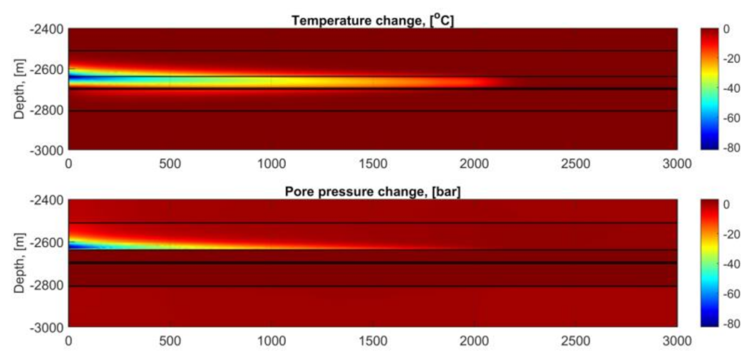
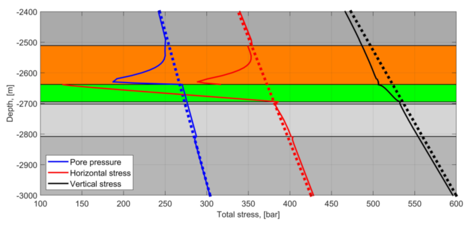
To validate the analytical model for drained and undrained situations (end-member boundary conditions), we compare the analytical to the numerical solution of a transient and fully coupled thermo-hydro-mechanical finite element method model (here using the commercially available code COMSOL MultiphysicsTM). Whereas the analytical solution effectively gives approximate stress change bounds at a specific location, the numerical approach including thermal and pressure diffusivity allows for investigation of changes at multiple locations, allowing for further recognition of critical areas (e.g., base caprock). The numerical model also relaxes some of the limitations in the analytical solution, such as stress arching and pore pressure dissipation and will also capture partial drainage scenarios.
Here, we present the numerical model used to simulate the cooling effect on the storage and sealing formations when cold CO2 is injected into a warm reservoir. The injection well is treated simply as a long horizontal well, and the model makes use of the symmetry perpendicular to the well trajectory to reduce the model dimension to a 2D problem. Figure 8 shows the horizons in the model between depth of −2400 m to −3000 m. The left boundary is a symmetry plane so that the total model width is 6000 m, and the vertical extent is from seafloor at −307 m to depth of −4000 m.
As before, the injection and cooling are assumed to occur in the Cook Fm. immediately below the sealing Drake Fm (an unlikely and unplanned but worst-case scenario for Phase 1 of the Northern Lights project). The numerical model describes the conservation of mass (fluid flow), energy (heat transfer) and momentum (force-balance). During operations, cold CO2 is injected and heat transfer occurs through both conduction and convection and the resulting heat transfer equation is
ρ c p eff T t + ρ f c p f q T κ eff T = 0 ,
where ρ c p eff is the effective volumetric heat capacity, ρ f is the density of the fluid, c p f is the specific heat capacity of the fluid, q is the Darcy flux which represents the coupling to fluid migration and κ eff is the effective thermal conductivity.
The effective parameters are calculated using arithmetic means of the rock and fluid properties and weighted with the volume fraction 1 ϕ and ϕ , respectively. As cold fluid is injected, the temperature is fixed at the inlet (left boundary in Cook Fm., 20 °C). In order to mimic that the cooling is strongest in the buoyant plume, the temperature at the inlet is described with a stronger cooling (lower temperature) in the upper parts of the inlet compared to the lower parts. This variation in cooling is approximated by a linear temperature profile that is 80 °C colder than the reservoir at the top of the inlet (by to the reservoir–caprock interface) and has the same temperature as the reservoir at the bottom (by the Cook Fm.–Burton Fm. interface). On the symmetry boundary, left in Figure 8, a no-flux boundary condition is used, while on all other outer boundaries the temperature is fixed at the initial temperature. The geothermal gradient is assumed to be 42 °C/km and the temperature varies linearly from the seafloor (4 °C) to the reservoir temperature of approximately 100 °C.
Although CO2 storage is introducing a non-wetting fluid phase (CO2) into a water-wet reservoir formation, the model here is simplified to a single-phase fluid flow problem that can be described by a mass conservation equation of the fluid:
ρ f S P p t + ρ f α ε v t + ρ f q = ρ f ϕ β f + α ϕ β s T t ,
The second term on the left-hand side of Equation (25) (the volumetric strain rate term) is the coupling to the momentum conservation equation (Equation (26)) and the right-hand side is the coupling to the heat transfer equation (Equation (24)). Injection of CO2 will increase the pore pressure P p in the reservoir and displace the formation water, introducing a flow-field in the reservoir. To mimic this behaviour, the reservoir is pressurised (3 bar increase relative to initial pore pressure P p , i n i ) and a representative and constant velocity field (Darcy flux in reservoir of 0.75 µm/s) is prescribed in the reservoir.
The system is initially in stress equilibrium; all stress changes are due to changes in temperature (thermal stress) and changes in pore pressure (poroelasticity). The initial vertical stress σ V , i n i is assumed lithostatic and linearly varying with depth and the horizontal stress is calculated using the K 0 value. The change in momentum balance, including the thermal and poroelastic stress contribution, can be expressed as
λ ε v I + 2 G ε + β T K Δ T I + α Δ P P I = 0 ,
where ε is the strain tensor, λ and G are the Lamé parameters, and I is the identity matrix. The Lamé parameters can be expressed by Young’s modulus E f r and Poisson’s ratio ν f r using common conversion formulae for isotropic materials. The top boundary has zero traction and is free to deform while all other outer boundaries have roller, or zero normal displacement, boundary conditions. The thermo-hydro-mechanical properties that are required to solve the model are given in Table 2.

5.2. Results

In the model, CO2 is injected for 25 years before it is stopped, and the pore pressure and temperature are allowed to dissipate for another 25 years. The changes in temperature and pore pressure after 50 years are shown in Figure 9. The temperature at the inlet is 80 °C colder than initial temperature in the injection formation (Cook Fm.). The temperature plume extends ~2.2 km into the reservoir, mainly due to convective transport from the inlet. Due to conductive transport, the cold injection fluid has also cooled down the lower part of the caprock, Drake Fm. This cooling has resulted in a contraction of the pore fluid, but because of the extremely low permeability in the caprock, the contraction results in a suction, or negative pore pressure change in the cooled parts, up to 80 bar at 10–15 m into the caprock (Figure 9, bottom).
The cooling effect on the reservoir and caprock is better visualised along a profile along the symmetry plane (left vertical boundary). The total vertical stress, total horizontal stress and total pore pressure are shown in Figure 10 before injection started (thick dotted lines) and after 50 years (solid lines).
The results show a small stress-arching effect in the vertical stress (black lines), due to a small stress reduction in the cooled areas. The reservoir (Cook Fm.) has a small pore pressure increase (3 bar) due to the injection which dissipates quickly into the Burton Fm. (shale layer) and Johansen Fm. below, resulting in a uniform pore pressure increase in these high-permeable formations (Cook, Burton and Johansen). However, in the tight caprock the pore pressure shows a strong reduction, up to 80 bar, due to contraction of the pore fluid and undrained conditions.
The numerical model also shows that the total horizontal stress in the injection reservoir is reduced to below the pore pressure (Figure 10); the total horizontal stress and pore pressure profiles in Cook are intersecting, resulting in a negative effective stress in the cooled parts (approximately top half of the injection reservoir, Cook Fm.), and thus there is a potential for thermal fracturing in the Cook formation. The same would have been observed in the caprock if the permeability was higher and experienced drained conditions. Instead, due to the combined effect of fluid contraction and low permeability of the caprock, the rock experiences undrained conditions. The transition from drained to undrained conditions becomes apparent when comparing the effective horizontal stress profiles from the numerical model to the analytical solutions for drained conditions (Equation (20)) and undrained conditions (Equation (22)) at various times, see Figure 11.
Considering the effective horizontal stress in the numerical model (black dashed line in Figure 11), the caprock experiences drained conditions at the interface with the reservoir (green–orange interface) and undrained conditions further away. This drained behaviour progresses slowly into the caprock with time and the analytical expressions for drained and undrained conditions represent the outer bounds of the draining behaviour of the caprock.
Figure 10 shows how the total stress components relate to the pore pressure and Figure 11 reveals how the profile in the effective stress (difference between stress and pore pressure) changes with time in the caprock. Effective stress below the tensile strength of the formation can result in tensile failure—the so-called internal integrity condition defined above. As shown, compressive effective stresses are maintained throughout. Another integrity criterion relates to the shear stress. The Local Factor of Safety (LFS) is here defined as the ratio of the Coulomb shear stress for the current state of stress and the Coulomb shear stress for the potential failure state. A value of LFS < 1 indicates a stable stress state. As temperature and pore pressure migrates in time, the LFS is also transient. In Figure 12, the LFS profile is plotted along the left boundary with the colour representing time, from blue to red. The Coulomb failure envelope for a rock depends on the cohesion and the friction coefficient. The LFS profiles in Figure 12 assumes zero cohesion and a friction coefficient of 30°, which are very conservative estimates yet illustrate the lower bounds of shear strength for a weakness that would be required to induce activation in the lower part of the caprock. We see that the LFS is generally below 1 with some exceptions, e.g., in the top parts of the Cook sands that also have negative effective stress. For the majority of the caprock package, the LFS remains below 1 for all times. Indeed, the undrained response due to cooling actually gives lower LFS and improved stability to shear failure. However, as pore pressure diffusion continues with time (and the results approach more drained conditions), we see that for the lower most few meters of the caprock which are closest to the Cook layer will potentially develop a LFS that is slightly in excess of 1 during the later years. We repeat again that these simulations are deemed worst case since the Cook has been assumed to be directly cooled from the CO2 injection—even though it is not the intended target reservoir for the CO2 and where there are shale barriers between the target sands and the Cook—and where zero cohesion strength has been assumed. Monte Carlo simulations of the drained case where uncertainties in the input parameters have been included indicate that there is less than 1% probability that shear failure will occur in the lower most Drake caprock due to cooling.

6. Summary and Discussion

While conservative and simplified conditions have been assumed here, we have demonstrated, both analytically and numerically, how thermal effects may under certain conditions lead to significant changes in caprock effective stress, primarily at the base of a caprock cooled by CO2. Specifically, given sufficient cooling, undrained conditions occurring in very low permeability shales can occur where the volumetric contraction of the rock framework (the pore) exceeds that of the pore fluid, leading to reduced pore pressures and subsequent increase in effective stress. If these instances are isolated, such effects are beneficial to caprock integrity (internal integrity). The opposing effect may also occur, leading to a reduction in caprock effective stress. This reduction, however, has not been observed to be so significant that it would lead to zero or negative effective stress scenarios, thus building confidence that the caprock maintains integrity despite severe cooling. However, if a degree of communication is assumed between the virgin and/or elevated pore pressures in a sand below the caprock, a local negative effective stress scenario may develop at the base of the caprock.
We repeat here a number of both simplifying and conservative assumptions used in this work:
  • Maximum cooling ( Δ T = −80 °C) in the sand directly below the primary Drake caprock seal. Injection of CO2 directly below the caprock is not planned for Phase 1 of the Northern Lights project and there is ~114 m of shale and sand between the top injection interval and the base Drake Fm that will retard the migration of the CO2 towards the caprock.
  • Both constant (spatially and temporally) formation and fluid properties are assumed. It is understood that this is a significant simplification of the true caprock/storage reservoir system and may have notable effects on the results shown here. This is particularly true of the Drake Fm., where, for example, variable mineralogy leads to large contrasts in the elastic properties [14]. Furthermore, large temperature differences are expected to influence formation and fluid properties.
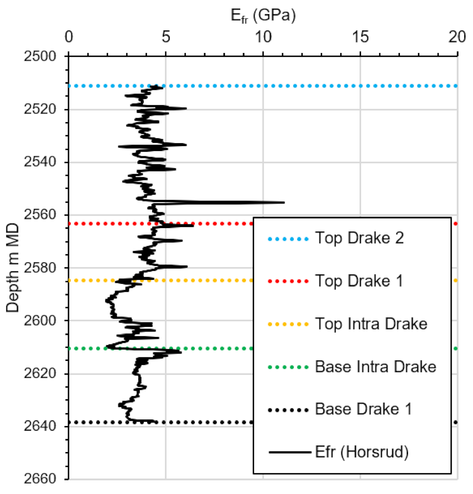
  • Formation properties are, per now, primarily based on log estimations.
  • End-member undrained or drained conditions are assumed. While this is partially accounted for in the numerical simulations, we understand the in situ process will be more complex and spatially variable.
  • Regarding external integrity loss, feedback loops/coupling between potential initial plastic development and subsequent changes in elevated pore pressure penetration are not considered.
For each of the categories above, efforts to improve and constrain assumptions are either ongoing or planned. For example, comprehensive laboratory testing is now on-going to confirm and/or constrain the relevant input (mechanical/thermal) properties and investigate more complex processes such as creep in high clay content shales, fracture healing mechanisms, etc. In addition, updated numerical simulations are ongoing to both consider variations in mechanical/thermal properties as observed in the Eos well as well as coupled fracture growth processes to better understand the true effects of non-elastic process development.

7. Conclusions

This investigation shows that pronounced thermal changes within the low permeability caprock may occur during CCS projects. Analytical and numerical approaches used here show how undrained effects within the low permeability caprock can lead to volumetric contraction differences between the rock framework and the pore fluid which induce both stress and pore pressure changes that need to be properly quantified. We show that such undrained effects, while inducing a more complicated response in the stress changes in the caprock, do not necessarily lead to unfavourable tensile conditions, and may, in fact, lead to increases in effective stress. Thus, we conclude that these effects are not expected to negatively affect the internal integrity of the caprock. Such evaluations build confidence in caprock’s ability to act as an effective seal, despite significantly changing thermal conditions. In fact, in the case of pore pressure reduction due to undrained thermal effects, effective stress in the caprock may increase, thus increasing its integrity from the static condition. We also investigate the case of pressure communication between the cooled and undrained caprock (with reduced effective stress) and virgin or elevated pore pressure in the storage sands, where it is observed that localised negative effective stress conditions may occur given large reductions in undrained caprock effective stress. We underline that the latter scenario is very conservative and unlikely as (A) extreme volumetric contraction difference conditions must occur in the caprock for maximum effective stress conditions, and (B) for the Northern Lights project, CO2 is not expected to come in contact with the primary caprock near the wellbore where temperature differences is at its largest (for both geologic and injector/development design reasons). We also note that increases in the total stress assumption within the caprock reduce the likelihood that negative effective stress conditions would occur (refer to the work in [14]). The mechanisms discussed in this work are based on simplified representations of the caprock character (e.g., homogeneity); significant work is on-going to further increase understanding of caprock heterogeneity. Better understanding of the relevant properties and coupling between the phenomena discussed may lead to an improved knowledge as to how thermal changes affect the caprock system.

Author Contributions

Conceptualization, N.T. and J.S.A.; methodology, N.T., J.S.A. and T.I.B.; software, T.I.B.; investigation, N.T., J.S.A. and T.I.B.; writing—original draft preparation, N.T., J.S.A. and T.I.B.; writing—review and editing, N.T., J.S.A. and T.I.B. All authors have read and agreed to the published version of the manuscript.

Funding

This research received no external funding.

Data Availability Statement

Refer to publicly available data [15].

Acknowledgments

The authors would like to thank Northern Lights Joint Venture DA and respective pre-joint venture partners (Equinor, Total and Shell) for constructive feedback and permission to publish this article and its contents, as well as Øystein Sæther for productive discussion on these topics.

Conflicts of Interest

The authors declare no conflict of interest.

References

  1. Northern Lights JV DA. Available online: https://northernlightsccs.com (accessed on 29 April 2021).
  2. Gassnova. Available online: https://ccsnorway.com (accessed on 29 April 2021).
  3. Hettema, M.; Bostrøm, B.; Lund, T. Analysis of Lost Circulation during Drilling in Cooled Formations. In Proceedings of the SPE Annual Technical Conference and Exhibition, SPE 90442, Houston, TX, USA, 26–29 September 2004. [Google Scholar]
  4. Perkins, T.K.; Gonzalez, J.A. The effect of Thermoelastic Stresses in Injection Well Fracturing. Soc. Pet. Eng. J. 2004, 25, 78–88. [Google Scholar] [CrossRef]
  5. Urpi, L.; Rinaldi, A.P.; Rutqvist, J.; Wiemer, S. Fault stability perturbation by thermal pressurization and stress transfer around a deep geological repository in a clay formation. J. Geophys. Res. Solid Earth 2019, 124, 8506–8518. [Google Scholar] [CrossRef]
  6. de Vries, A.; Ita, J.; Shinde, A.; van Eijs, R.; Davison, M.; Bauer, A. Geomechanical aspects of injecting CO2 in an underground depleted gas reservoir. In Proceedings of the 9th Euroconference on Rock Physics and Geomechanics, Trondheim, Norway, 17–21 October 2011. [Google Scholar]
  7. McDermott, C.; Williams, J.; Tucker, O.; Jin, M.; Mackay, E.; Edlmann, K.; Haszeldine, R.S.; Wang, W.; Kolditz, O.; Akhurst, M. Screening the geomechanical stability (thermal and mechanical) of shared multi-user CO2 storage assets: A simple effective tool applied to the Captain Sandstone Aquifer. Intl. J. Greenh. Gas Control 2016, 45, 43–61. [Google Scholar] [CrossRef] [Green Version]
  8. Vilarrasa, V.; Olivella, S.; Rutqvist, J.; Rutqvist, J. Long term impacts of cold CO2 injection on the caprock integrity. Int. J. Greenh. Gas Control 2014, 24, 1–13. [Google Scholar] [CrossRef]
  9. Zaki, S. Modelling Fracture Propagation in Shale Cap Rocks Cooled by CO2 Injection. Master’s Thesis, Imperial College London, Department of Earth Science and Engineering, London, UK, 2013. [Google Scholar]
  10. Bjørnarå, T.I.; Park, J.; Marin-Moreno, H.M. Geomechanical integrity and non-isothermal effects in CO2 storage. In Proceedings of the 15th Greenhouse Gas Control Technologies Conference, Abu Dhabi, United Arab Emirates, 15–18 March 2021; Available online: https://ssrn.com/abstract=3811357 (accessed on 5 August 2021). [CrossRef]
  11. Soltanzadeh, H.; Jafari, A. Thermo-poro-mechanical analysis of effects of low-temperature CO2 injection on caprock integrity. In Proceedings of the SPE Unconventional Resources Conference, SPE-167249-MS, Calgary, AB, Canada, 5–7 November 2013. [Google Scholar]
  12. Meneguolo, R.; Målbakken, T.; Galvani, L.; Kassold, S.; Vazquez Anzola, D.A. Subsurface contributions to the Northern Lights CO2 storage project sanction: Planning for success in an unexplored license. In Proceedings of the SPE Aberdeen Carbon Capture Utilisation and Storage Conference, Virtual Event, 26 October 2020. [Google Scholar]
  13. Meneguolo, R.; Sundal, A.; Martinius, A.W.; Veselovsky, Z.; Cullum, A. Anatomy of the Lower Jurassic Dunlin Group for the Aurora CO2 storage site, EL001, Northern North Sea, Norway. Int. J. Greenh. Gas Control 2021. under review. [Google Scholar]
  14. Thompson, N.; Andrews, J.A.; Meneguolo, R.; Wu, L. Characterization of the in-situ stress on the Horda platform—A study from the Northern Lights Eos well. Int. J. Greenh. Gas Control 2021. under review. [Google Scholar]
  15. Sharing Data from Northern Lights Well. Available online: https://www.equinor.com/en/news/20201019-sharing-data-northern-lights.html (accessed on 3 August 2021).
  16. Horsrud, P. Estimating mechanical properties of shale from empirical correlations. SPE Drill. Complet. 2001, 16, 68–73. [Google Scholar] [CrossRef] [Green Version]
  17. McTigue, D.F. Thermoelastic Response of Fluid-Saturated Porous Rock. J. Geophys. Res. 1986, 91, 9533–9542. [Google Scholar] [CrossRef]
Figure 1. Potential penetration of cooling into Drake caprock after 25 years cooling assuming a constant (cooled) temperature of the underlying Cook sands.
Energies 14 05054 g001
Figure 2. Contraction of fluid ( Δ V f l u i d ) and pores ( Δ V p o r e = Δ V b u l k Δ V g r a i n ) due to cooling. When the pores contract more than the fluid the fluid is compressed, fluid pressure increases, and vice versa, when the contraction of the fluid is bigger than the contraction of the pores the fluid pressure decreases.
Energies 14 05054 g002
Figure 3. Framework elastic moduli estimations, Drake formation.
Energies 14 05054 g003
Figure 4. Effective horizontal stress ( σ h ) in the shale caprock from cooling with an undrained response. Results from Monte Carlo simulation for given different temperature reductions.
Energies 14 05054 g004
Figure 5. Potential effective stress profiles versus distance above base Drake/top Cook, after 25 years of cooling.
Energies 14 05054 g005
Figure 6. Potential effective stress profile (P1—1 percentile case) distance above base Drake/top Cook after 25 years of cooling for two extreme cases (fully drained and undrained).
Energies 14 05054 g006
Figure 7. Potential for fracturing of immediate caprock, undrained response of immediate caprock to cooling in relation to virgin pore pressure at top Cook.
Energies 14 05054 g007
Figure 8. The various horizons specified in the numerical model. The depths are relative to mean sea level. The seafloor is at depth 307 m, which is the top boundary of the model, and the bottom boundary of the model is located at 4000 m. The width of the model is 6000 m. Cook Fm. (green) is the injection reservoir. The numbers indicate the bottom and the thickness of each formation.
Energies 14 05054 g008
Figure 9. Temperature and pore pressure state after 50 years. (Top) temperature change, (bottom) pore pressure change.
Energies 14 05054 g009
Figure 10. Vertical profiles of pore pressure (blue), total horizontal stress (red) and total vertical stress (black) for initial state (thick dotted lines) and after 50 years (solid lines). Injection reservoir (Cook Fm.) is green and caprock (Drake Fm.) is orange.
Energies 14 05054 g010
Figure 11. Comparison of the effective horizontal stress in caprock (Drake Fm.) in the numerical model (black dashed curves) to the effective horizontal stress calculated using analytical expression for drained conditions (red curves, Equation (20)) and undrained conditions (blue curves, Equation (22)).
Energies 14 05054 g011
Figure 12. Local Factor of Safety (LFS), profiles along the left boundary, from zero to 50 years (blue to red coloured curves), initial profile is white dashed line. LFS < 1 indicates a stable condition.
Energies 14 05054 g012
Table 1. Parameter value assumptions.
ParameterSymbolUnitMin.MeanMax.
Water coeff. vol. therm. Expansion * β f 1/°C5.10 × 10−45.66 × 10−46.23 × 10−4
Water compressibility c f = 1 / K f 1/bar-3.5 × 10−5-
Solid grain bulk modulus K S GPa-37-
Bulk rock coeff. lin. therm. expansion β T 1/°C-1.2 × 10−5-
Solid grain coeff. vol. therm. expansion β S v o l 1/°C-1.2 × 10−5-
Porosity ϕ -0.050.080.2
Framework Poisson’s ratio ν f r -0.20.250.3
Framework elastic modulus ** E f r GPa2.63.84.7
Effective stress ratio *** P p ,   i n i bar 265
Vertical stress *** K 0 - 0.41
* As estimated from relevant PVT tables, min. and max. represent −/+ 10%, ** Represent P10, mean and P90 values from Figure 3. *** Based on NO 31/5-7 wellbore stability model at base Drake 1 Fm.
Table 2. Thermo-hydro-mechanical properties of the various formations in Figure 8 (geometry) and fluid.
ParameterSymbolUnitOverburden/UnderburdenDrakeCookBurtonJohansenPore Volume Brine
Thermal conductivity κ W/m/K1.440.577
Thermal heat capacity c p J/kg/K837.364187
Thermal exp., bulk, linear β T 1/K1.25 × 10−55.66 × 10⁻⁴
Thermal exp., grain, vol. β s 1/K1.25 × 10−5NA
Permeability k m210−215 × 10−132 × 10−155 × 10−13NA
Porosity ϕ -0.080.220.140.23NA
Framework elastic mod. E f r GPa11.1/2.33.81812.39.7NA
Poisson’s ratio ν f r -0.18/0.110.250.330.110.24NA
Density ρ kg/m32563 *2150 *1030
Viscosity η f cpNA0.37
* For rock formations—grain density.
Publisher’s Note: MDPI stays neutral with regard to jurisdictional claims in published maps and institutional affiliations.

