Article

Estimation Method of Greenhouse Gas Reduction for Electrical Energy Storage Based on Load-Leveling Application

Department of Electrical Engineering, Korea University of Technology & Education (KUT), Cheonan 31253, Korea
*
Author to whom correspondence should be addressed.
Submission received: 28 July 2021 / Revised: 23 August 2021 / Accepted: 27 August 2021 / Published: 2 September 2021
(This article belongs to the Special Issue Industry and Tertiary Sectors towards Clean Energy Transition)

Abstract

:
In recent years, there have been several types of energy storage technologies adopted in many different areas, such as peak shaving, frequency regulation, and renewable stabilization applications. Moreover, technologies of high energy and power density are useful for load leveling, power smoothing for renewable energy systems (RESs), and peak shaving for demand management. Under these circumstances, an estimation technique for assessing environmental issues applied to electrical energy storage (EES) systems is essential in order to promote commercialization of EES systems. Therefore, this paper proposes an estimation method for CO2 emission in cases where EES systems are introduced and not introduced. It is essential to evaluate environmental issues in EES systems at operation stages of their life cycle and make an effective contribution to environmental improvement and reduce potential adverse environmental impacts. Thus, this paper deals with an evaluation method for CO2 emission based on an optimal algorithm including a successive approximation method for the best-mix solution of power sources, etc. From the simulation result based on the proposed evaluation algorithm, it is found that the output power of a coal power plant (high CO2 emission) is replaced by the output powers of the EES systems and the nuclear generator (low CO2 emission).

1. Introduction

Recently, the operation of electric power systems has become more difficult because the peak load demand is increasing continuously and also the daily and annual load factors are worsening [1,2]. Furthermore, the global environmental issues need to be considered in electric power systems [3,4,5,6]. One countermeasure to overcome these problems is a study of the operation method of electric power systems, including novel energy storage systems such as secondary batteries, superconducting magnets (SMES), and flywheels, which have made astonishing improvements lately [7,8,9].
In general, the cost of power generation can be reduced if the energy storage system is charged during the off-peak time interval and discharged during the peak time interval [10]. In addition, the benefit of storing electricity is increasing along with the increase in the difference in demand between off-peak and peak time intervals. The result is load leveling by time shifting [11]. Furthermore, the output of power generation can be flatter if the difference in demand between daytime and nightime is reduced using an EES system; as a result, the operation efficiency can be improved and the fuel cost can be reduced [12]. For these reasons, a lot of utilities have built pumped hydro-generators and have started installing large-scaled batteries in substations recently [13].
In contrast, it is expected that an RES such as a PV system or a wind power system will be widely installed and operated in order to overcome global environmental issues [14]. However, operation problems such as output fluctuation or unpredictability may occur if the RES is integrated with the power grid [15]. When the total volume of renewable energies connected to the grid exceeds a certain level, such problems will appear and countermeasures will be needed. To stabilize the fluctuation and to control load management, an EES system is essential for the introduction of large amounts of renewable energy [16,17,18,19].
Under these circumstances, an estimation technique for assessing environmental issues applied to EES systems is essential in order to promote commercialization of EES systems. However, when introducing an EES system, many previous studies have been conducted on their merits in terms of economic dispatch, but studies evaluating the environmental merits are insufficient [20,21]. Therefore, this paper presents a concept of an estimation method for CO2 emission in cases where EES systems are introduced and not introduced. It is based on the idea that can reduce CO2 emission by existing generator units by operation of EES systems.
It is essential to evaluate environmental issues in EES systems at operation stages of their life cycle and make an effective contribution to environmental improvement and reduce potential adverse environmental impacts. Thus, this paper proposes an evaluation method of CO2 emission based on an optimal algorithm including a successive approximation method for the best-mix solution of power sources, etc. From the result of calculating the CO2 emission using the proposed evaluation algorithm of GHG reduction, it is found that the output power of the coal power plant (high CO2 emission) is replaced by the output powers of the EES systems and the nuclear generator (low CO2 emission).

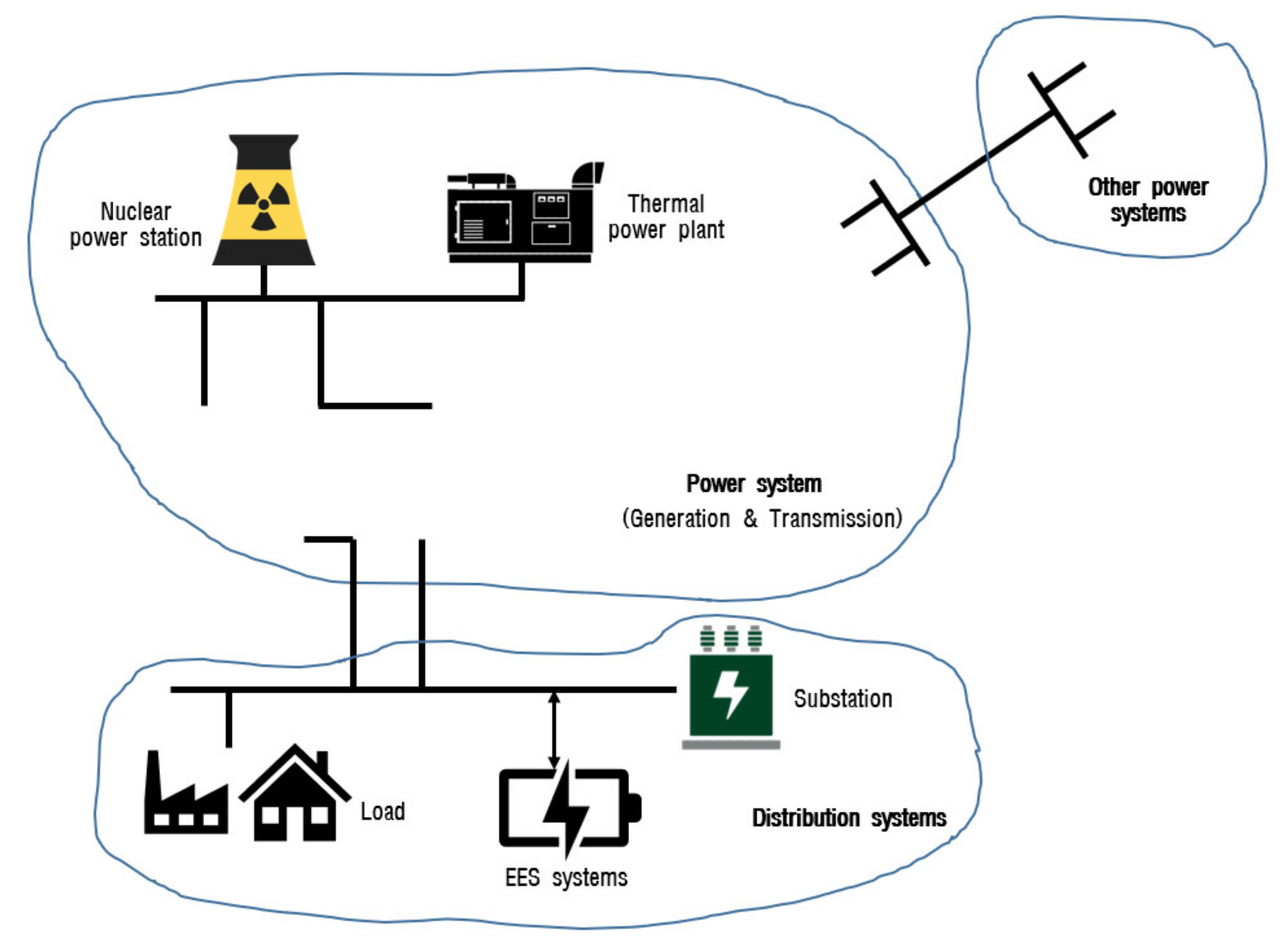
2. Formulation of Load-Leveling Application Using EES Systems

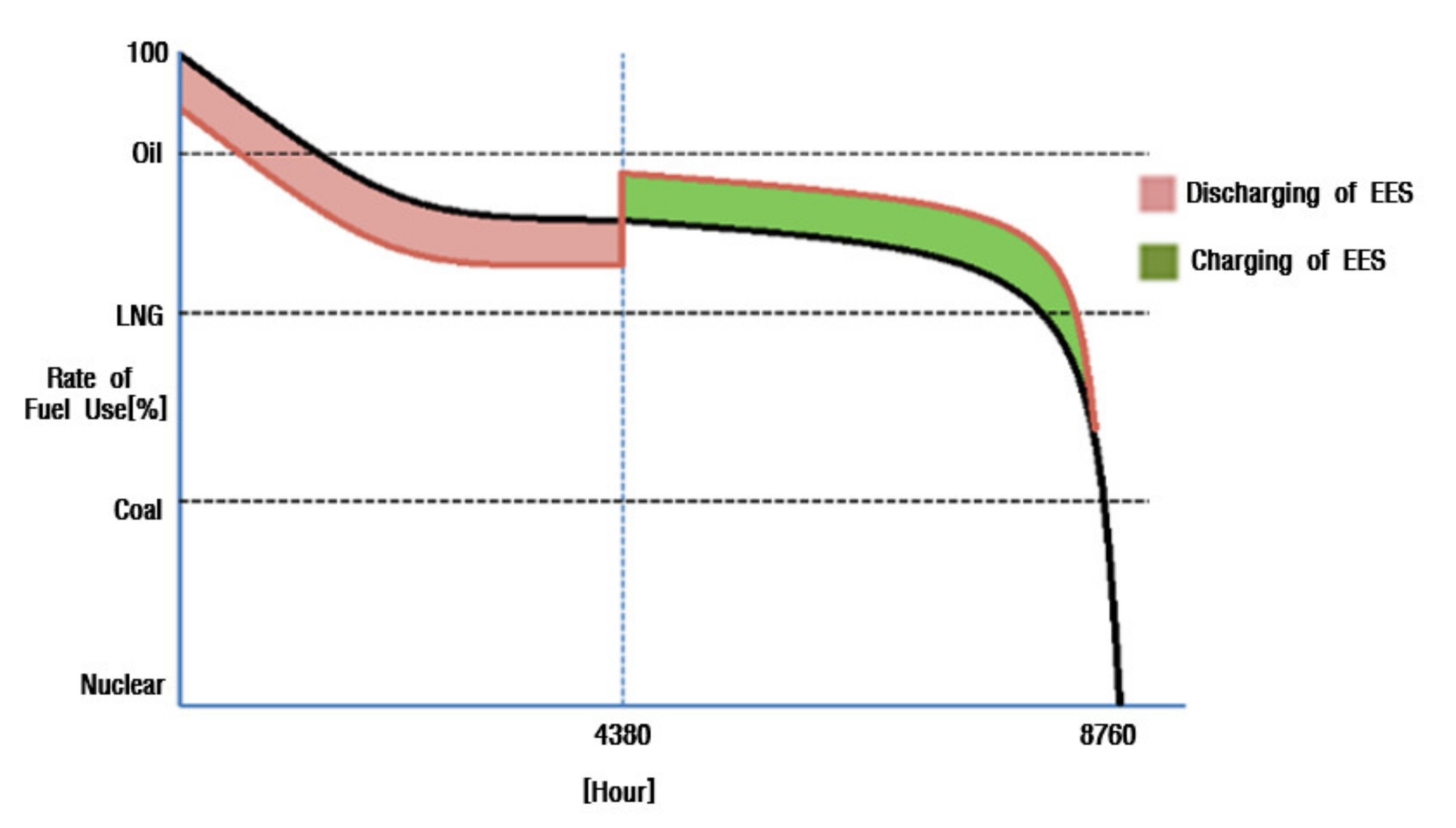
2.1. Concepts of Load Leveling

To estimate GHG reduction for EES systems, the proper charging and discharging amounts of EES systems must be obtained in advance, in other words, the composition ratio of generation units at a peak load demand for the two cases where EES systems are introduced and not introduced. This means that the output power of the oil-power plant (high CO2 emission) is replaced by the output powers of the EES systems and the nuclear power plant (low CO2 emission). With the allocation of EES systems to distribution systems in Figure 1, the simultaneous load leveling of both the total power system and the distribution systems increases the utilization rates of less expensive generator units, and the benefit of the reduction in the total power operation cost is expected, as shown in Figure 2. In other words, the operation problem of load leveling is to obtain the most appropriate type and number of generators, called an optimal generation mix, in cases where EES systems are introduced and allocated to distribution systems [22,23,24,25].

2.2. Problem Formulation of Load-Leveling Application

As mentioned above, the fundamental problem of load leveling is to decide the most appropriate type and number of generators, called an optimal generation mix, in cases where EES systems are operated in the power (distribution) systems [26]. The optimal generation mix with EES systems is a static problem against the time period and in which the objective is to determine the process in such a manner as to minimize the total cost for load demands provided for a target year [27]. Both both the generation mix (nonlinear integer programming problem) and the operating mode of EES systems (nonlinear programming problem) must be optimized. The problem can be thus formulated and solved as a nonlinear mixed integer programming problem. However, the nonlinear mixed integer programming problem will be complicated, along with the dimension of the problem. The optimal generation mix problem considering EES systems, whose objective is to determine the generation mix that minimizes the total cost for a target year, can be formulated as a nonlinear mixed integer programming problem as follows [28]:
M i n F n ( x , v ) = i = 1 n [ a i x i + b i Q i ( X i 1 , X i 1 + x i , v ) ] + a s x s
Subj .   to   i = 1 n x i + x s P D + P R
x i min x i x i max , i = 1 , , n
v i min v i k v i max , i = 1 , , n , k = 1 , , T
Q i ( X i 1 , X i 1 + x i , v ) = k = 1 K [ z k X t 1 X t 1 + X t L k ( u , v i k ) d u ] , i = 1 , , n
X i = k = 1 i x k , i = 1 , , n , X 0 = 0
where F n is the total cost for the target year; n is the number of generation types; a i ,   b i are the fixed and variable costs, respectively, of generation type I; x i ,   x s are the capacity of generation type i and EES systems, respectively; a s is the fixed cost of EES systems; v i k is the output power of EES systems at a daily load curve i and time period k; Q i is the annual energy production for generation type i; X i is the cumulative capacity up to generation type i; L k ( u ) is the time fraction that demand is more than load level u at duration curve k; z k is the number of days that provide L k ( u ) ; P D ,   P R are the peak demand and spinning reserve, respectively; K is the number of patterns of the daily load duration curve; and T is the number of time intervals for the daily load duration curve.

3. Evaluation Algorithm of GHG Reduction Based on Load Leveling

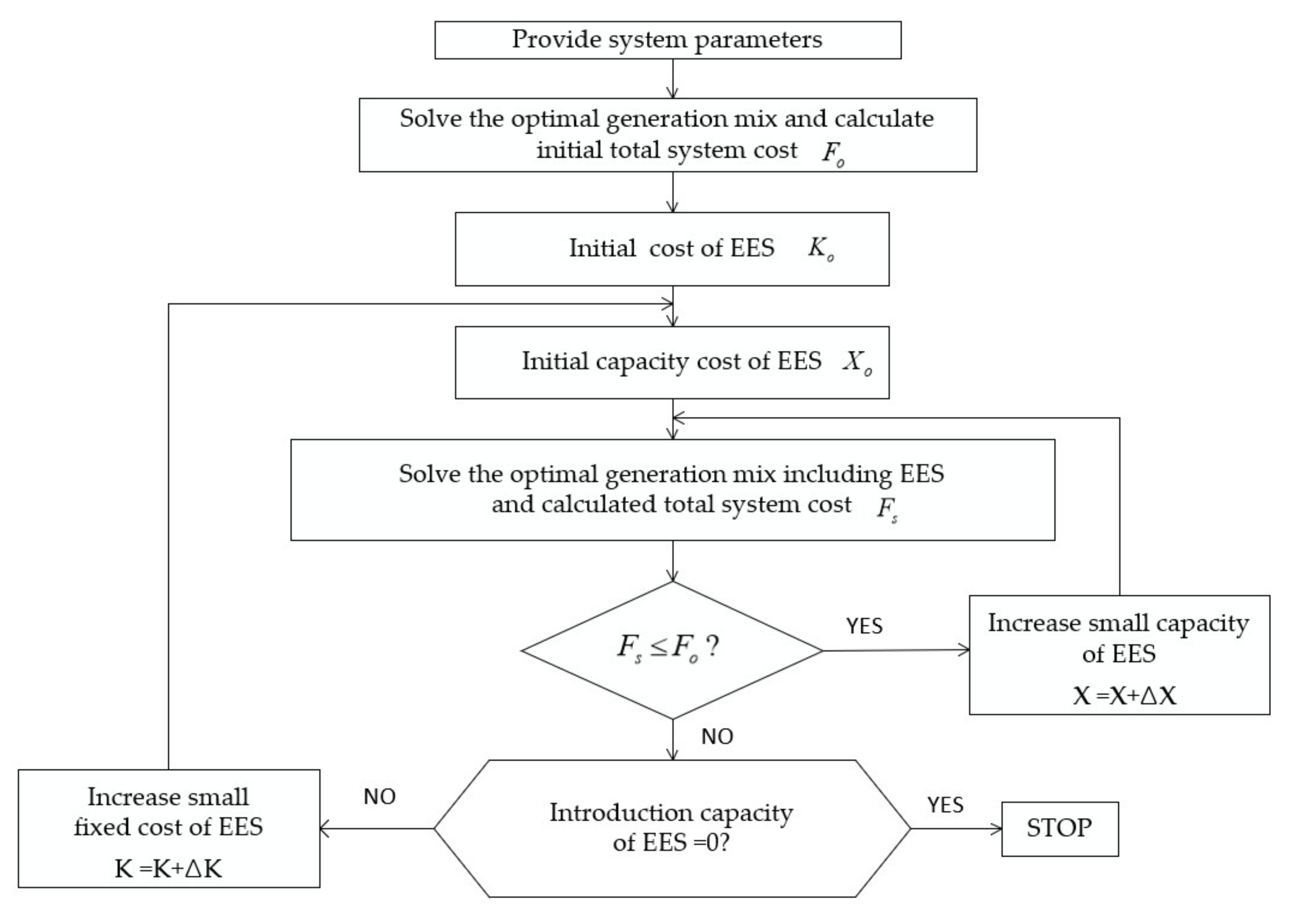
3.1. Optimal Operation Algorithm for Load Leveling

The problem, as formulated above, which is composed of two kinds of variables, such as generation mix (x) and operating mode of EES systems (v), is a nonlinear mixed integer programming problem. From a theoretical perspective, the problem can be solved by evaluating the objective function for the generation mix (x) under the constraint conditions. However, this method will be complicated with the increase in the system size. Therefore, this paper adapts a successive approximation method considering the parameters of the fixed cost and capacity of EES systems, as shown in Figure 3. The optimization procedure can be illustrated as follows:
  • <Step1> Assumes system parameters. Put K 0 = 0 (fixed cost of EES systems) and X 0 = 0 (initial capacity of EES systems).
  • <Step2> Determines the optimal generation mix for existing generators (x) while fixing the output power of EES systems to zero (v = 0). Assume F 0 as the total cost of this solution.
  • <Step3> Determines the optimal operating mode of EES systems (v) while fixing the generation mix (x). Calculate the optimal generation mix with EES systems, Fs.
  • <Step4> If F s F 0 , add the unit size of EES systems Δ X and go to <Step3>. Otherwise, go to the next step.
  • <Step5> If the introduction capacity of EES systems is zero (X = 0), the algorithm terminates. The generation mix (x) and the capacity and fixed cost of EES systems are the optimal solution. Otherwise, increase the unit fixed cost of EES systems Δ K and go to <Step3>.

3.2. Operation Algorithm of EES Systems

This section describes the algorithm to determine the optimal operation of an EES system while fixing the generation mix of existing generators. This paper adopts a gradient method to decide the optimal operation mode of the EES system. Therefore, the economic operating conditions for the EES system are obtained by Equation (7).
η > λ c h a r g e λ d i s c h a r g e  
where η is the round-trip efficiency of the EES system, λ c h a r g e is the incremental cost in the charging period, and λ d i s c h a r g e shows the incremental cost in the discharging period of the EES system.
The minimization for the objective function F n , while fixing the generation mix, is obtained by load leveling in order to satisfy the economic operating conditions. The constraint of power (kW) and capacity (kWh) in EES systems must be also satisfied in this procedure. The optimal operation mode of EES systems over the target year is decided, along with all daily duration curves. The procedure is as follows:
  • <Step1> Decide the lowest and highest load demand periods in the daily load duration curve. Compute the incremental costs λ c h arg e and λ d i s c h arg e .
  • <Step2> If η < λ c h arg e / λ d i s c h arg e , the algorithm terminates. Otherwise, charge a small amount of power Δ P S in the lowest period, and discharge the power η Δ P S in the highest period.
  • <Step3> If the maximum storage capacity (kWh) constraint is reached, the algorithm terminates.
  • <Step4> If the maximum output (kW) constraint for EES systems is reached, eliminate the period from consideration. Go to <Step1>.
In addition, the allocation site of each small amount for EES systems is decided by selecting the lowest F n (x) for the cases where the above algorithm is applied at all allocation sites that are the distribution substations.

3.3. Estimation Algorithm of GHG Reduction Based on Load Leveling
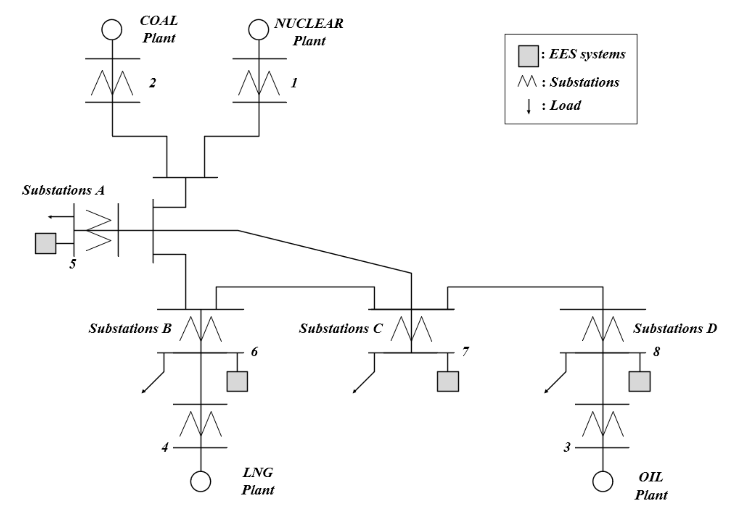
With the allocation of EES systems to distribution systems, the benefit of the reduction of the total power operation cost is expected because the simultaneous load leveling of both the total power system and the power distribution systems increases the utilization rates of less expensive generator units such as nuclear and coal power plants. In addition, if EES systems are replaced with existing generators in the peak (discharging) time interval, the benefit of CO2 emission reduction can be expected, where it is ideally assumed that EES systems are charged by the nuclear power unit in the off-peak time and discharged by oil or gas generator units in the peak time. Therefore, the estimation of GHG reduction during a year can be quantified using the formula given below:
G H G ( y ) = t = 1 T i = 1 n P D E i ( t ) × α i t = 1 T i = 1 n P C E i ( t ) × β i t = 1 T P E S S ( t ) × η i n , o u t × γ E S S
Subj .   to   i = 1 n P D E i P E S S = 0
where G H G ( y ) is the GHG reduction amount a year (kt), P D E i ( t ) is the output (kW) of the existing generators in peak (discharging) times, P C E i ( t ) is the output (kW) of the existing generators in off-peak (charging) times, P E S S ( t ) is the charging and discharging output (kW) of the EES systems, α i is the CO2 emission coefficient of the generator units in the discharging time, β i is the CO2 emission coefficient of the generator units in the charging time, γ E S S is the CO2 emission coefficient of the EES systems, i is the generator type, t is the time interval, T is the target year, and η i n , o u t is the charging and discharging efficiency (loss) of the EES systems.
To find out G H G ( y ) , the proper charging and discharging amounts of EES systems must be obtained in advance, in other words, the composition ratio of generation units at a peak load demand for the two cases where EES systems are introduced and not introduced. This means that the output power of the oil power plant (high CO2 emission) is replaced by the output powers of the EES systems and the nuclear power plant (low CO2 emission).

4. Case Studies

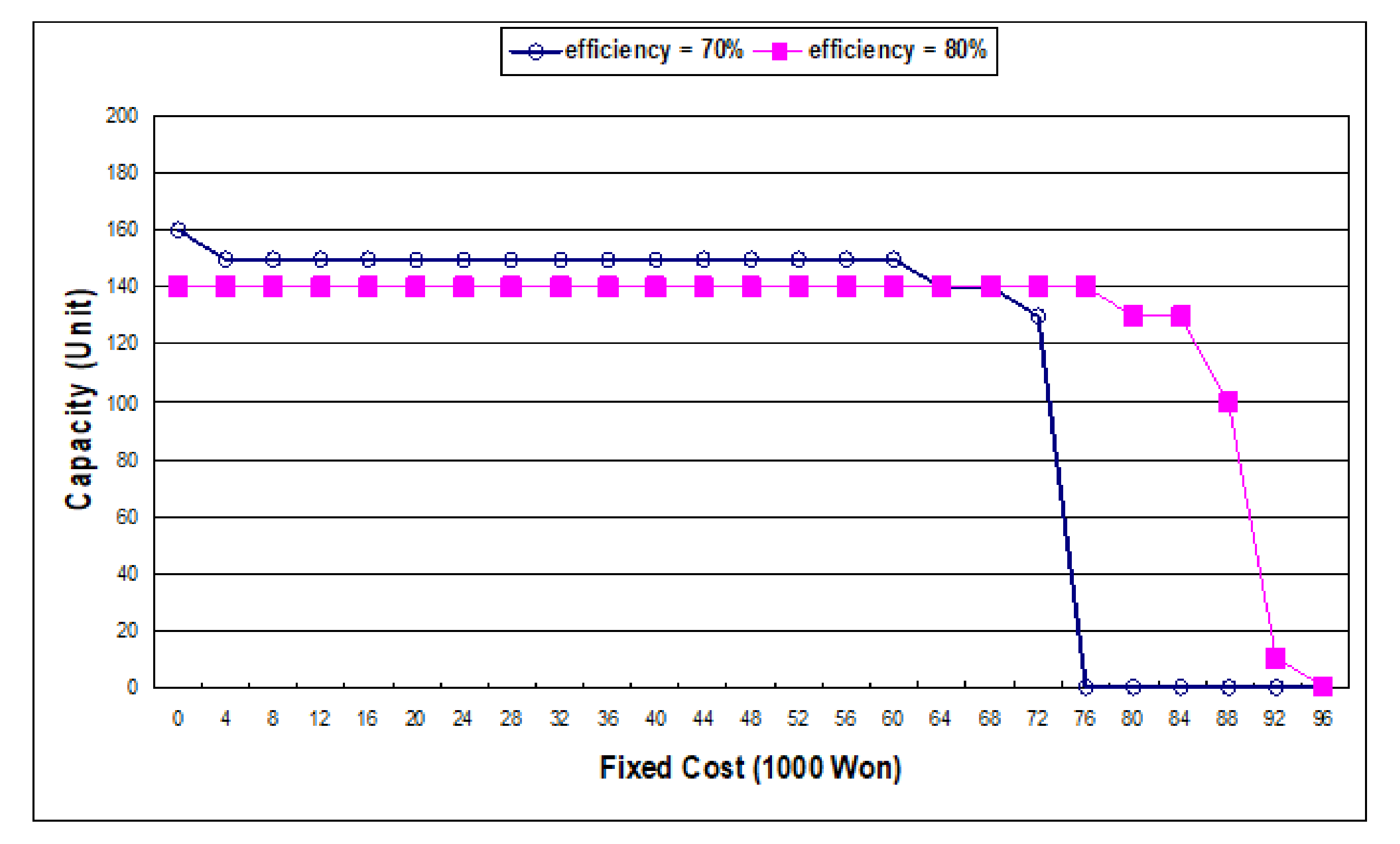
4.1. Simulation Conditions

To validate the proposed method, this paper carried out simulations using the model systems and parameters shown in Figure 4 and Table 1. The table is the data of the statistical materials of the Korea Electric Power Cooperation in the fiscal year of 2018. The four load patterns for distribution substations (A, B, C, D) and the peak demand of 10 million kW in Figure 5 were considered. This figure is the typical load pattern in summer, and the load patterns of other seasons were assumed by the same pattern and the size of 70%, 80%, and 90% based on the typical load pattern. In addition, the round-trip efficiencies for EES systems of 70% and 80% were assumed. Furthermore, the CO2 emission amount of the generator type was assumed, as shown in Table 2, in order to find out GHG reduction based on load leveling in EES systems. This paper found out the optimal generation mix, considering the operation of EES systems under the following assumptions [29,30,31,32]:
The total cost of generators is calculated by the sum of the variable and fixed costs, and the total cost of EES systems is only the fixed cost.
The maintenance cost of generators is ignored.
Unit sizes for the existing generators are previously provided, and unit sizes for new generators are not fixed.

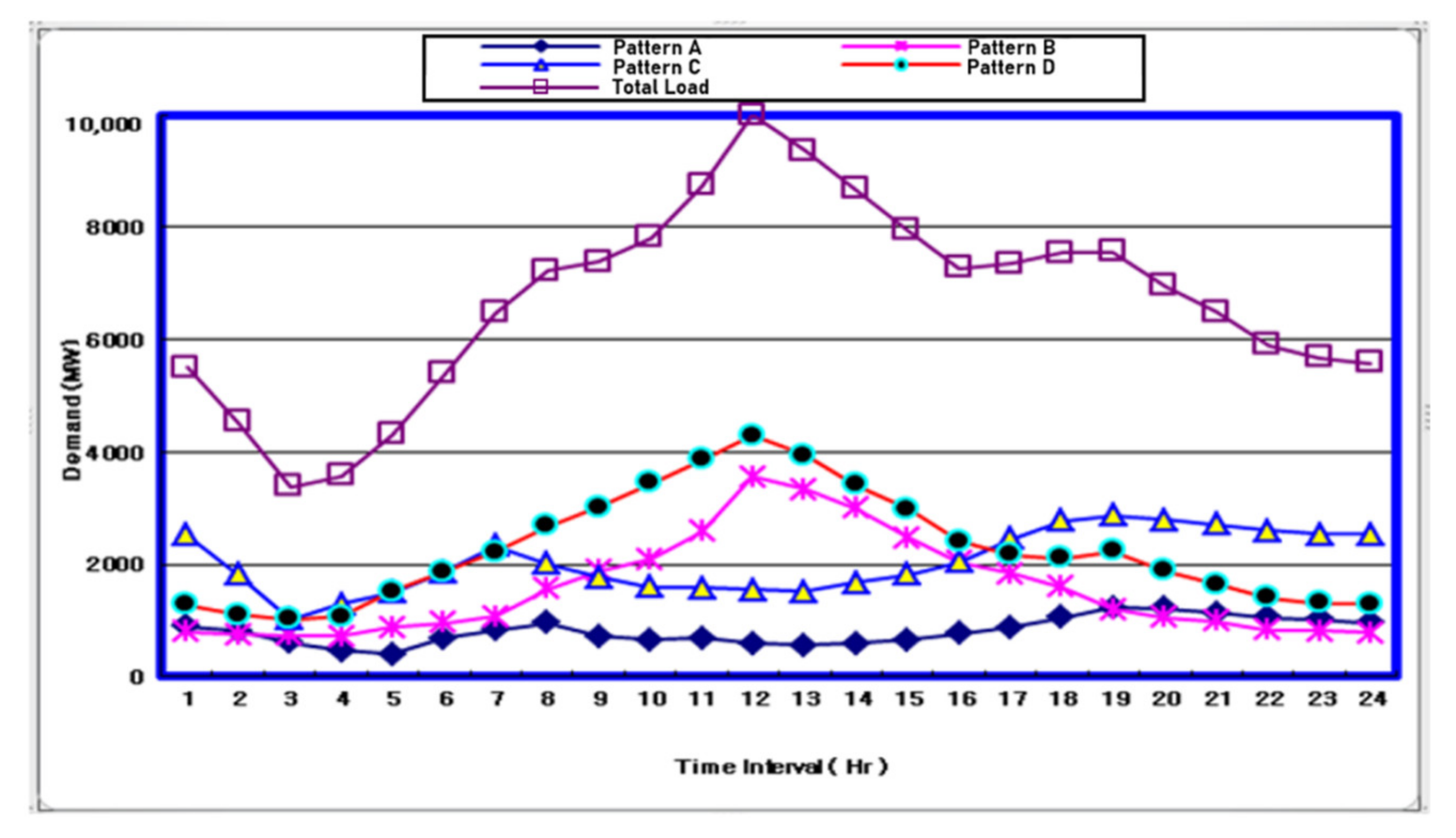
4.2. Operation Characteristics of Load Leveling

By comparing the total operation cost F n (x) and F 0 (x) for the two cases where EES systems are introduced and not introduced, with the increase in a small unit of the capacity and fixed cost of EES systems, the optimal capacity and fixed cost of EES systems are obtained, as shown in Figure 6. Because of the computation time for parameter analysis, a small unit of the capacity of EES systems is considered as 20 MW (160 MWh, 8 h) and the fixed cost of EES systems is considered as 1000 won. Figure 6 shows that the benefits of the load leveling of EES systems in the distribution substations, which is the fixed cost ( C a ), becomes 75,000~94,000 won/kW.
As shown in Figure 6, the marginal and saturated fixed costs are also obtained. The marginal cost, in which the composition ratio of EES systems is zero, represents the economical point for EES systems. In addition, the saturated fixed cost keeps a constant value, although the fixed cost changes, because complete load leveling is accomplished at each fixed cost. Table 3 shows the comparison results for the composition ratios of generation units and the total cost at a fixed cost of 75,000 won for the two cases where EES systems are introduced and not introduced.

4.3. Estimation of GHG Reduction Based on Load Leveling

Based on the operation characteristics of EES systems, as shown in Section 4.2, this paper ideally assumes that EES systems are charged by the nuclear power unit in off-peak time and discharged by the oil power plant (heavy oil steam boiler) units in peak time. Here, the total capacity of EES systems is calculated as 2600 MW (8 h, 20,800 MWh) and the efficiency of EES systems is also assumed as 80% for load leveling. Therefore, the amount of GHG reduction during a year can be obtained as 5785.14 kt based on the following procedure:
P D E i ( t ) / year = 365   days × 20,800   MWh × 780   kt / MWh × 10 6 = 5921.8   kt
P C E i ( t ) / year = 365   days × 20,800   MWh × 15   kt / MWh × 10 6 = 113.88   kt
P E S S ( t ) η i n , o u t / year = 365   days × 20,800   MWh × ( 1 0.8 ) × 15   kt / MWh × 10 6 = 22.78   kt
G H G ( y ) = 5785.14   kt
However, if the coal power plant is replaced with an oil power plant (heavy oil steam boiler) for discharging EES systems during the peak-time interval, the annual amount of GHG reduction can be calculated as 7265.54 kt based on the following procedure:
P D E i ( t ) / year = 365   days × 20,800   MWh × 975   kt / MWh × 10 6 = 7402.2   kt
P C E i ( t ) / year = 365   days × 20,800   MWh × 15   kt / MWh × 10 6 = 113.88   kt
P E S S ( t ) η i n , o u t / year = 365   days × 20,800   MWh × ( 1 0.8 ) × 15   kt / MWh × 10 6 = 22.78   kt
G H G ( y ) = 7265.54   kt
Therefore, it is clear that the amount of GHG reduction with a coal power plant is more effective than with an oil power plant for charging the power of EES systems.

5. Conclusions

This paper presents a concept of an estimation method for CO2 emission based on an optimal algorithm including a successive approximation method for the best-mix solution of power sources, etc. The main results are summarized as follows.
(1)
From the optimal operation algorithm of EES systems, the benefits of load leveling in the distribution substations is calculated as 75,000~94,000 won/kW for 1 year.
(2)
The total amount of GHG reduction with an oil power plant is calculated as 5785.14 kt, and that with a coal power plant is obtained as 7265.54 kt. The amount of GHG reduction with a coal power plant is more effective than with an oil power plant for charging the power of EES systems.
(3)
It is confirmed that the output of the coal power plant with high CO2 emission is replaced by the EES systems and the nuclear power plant with low CO2 emission. Therefore, it is confirmed that EES systems affect the environment at operation stages of their life cycle and contribute to environmental improvement and reduction in potential adverse environmental impacts.

Author Contributions

D.-H.T. and D.-S.R. carried out modeling and simulations and compiled the manuscript. The literature review and simulation analysis were performed by H.-D.L. and B.-G.H., and J.S. collected the data and investigated early works. All authors have read and agreed to the published version of the manuscript.

Funding

This research was funded by the Power Generation and Electricity Delivery Core Technology program of the Korea Institute of Energy Technology Evaluation and Planning (KETEP), with financial resources from the Ministry of Trade, Industry & Energy, Korea.

Institutional Review Board Statement

Not applicable.

Informed Consent Statement

Not applicable.

Data Availability Statement

The raw data analyzed in this article are available online at: https://www.iso.org/standard/41352.html and https://webstore.iec.ch/publication/7520 (accessed on September 2008 and 14 June 2012).

Acknowledgments

This work was supported by the Power Generation and Electricity Delivery Core Technology program of the Korea Institute of Energy Technology Evaluation and Planning (KETEP), with financial resources from the Ministry of Trade, Industry & Energy, Republic of Korea (nos.20191210301940 and 20206910100090).

Conflicts of Interest

The authors declare no conflict of interest.

References

  1. IEA. Impact of Smart Grid Technologies on Peak Load to 2050; IEA: Paris, France, 2011. [Google Scholar]
  2. Ministry of Trade, Industry and Energy. The Fifth National Basic Plan for New and Renewable Energies (2014–2035); Ministry of Trade, Industry and Energy: Seoul, Korea, 2020.
  3. Alsharif, M.H.; Yahya, K.; Geem, Z.W. Strategic Market Growth and Policy Recommendations for Sustainable Solar Energy Deployment in South Korea. J. Electr. Eng. Technol. 2020, 15, 803–815. [Google Scholar] [CrossRef]
  4. Dincer, I. Renewable energy and sustainable development: A crucial review. Renew. Sustain. Energy Rev. 2000, 4, 157–175. [Google Scholar] [CrossRef]
  5. Elnozahy, A.; Yousef, A.M.; Ghoneim, S.S.; Abdelwahab SA, M.; Mohamed, M.; Abo-Elyousr, F.K. Optimal Economic and Environmental Indices for Hybrid PV/Wind-Based Battery Storage System. J. Electr. Eng. Technol. 2021, 1–16. [Google Scholar]
  6. Bahramara, S.; Parsa Moghaddam, M.; Haghifam, M.R. Optimal planning of hybrid renewable energy systems using HOMER: A review. Renew. Sustain. Energy Rev. 2016, 62, 609–620. [Google Scholar] [CrossRef]
  7. Tixador, P. Superconducting Magnetic Energy Storage: Status and Perspective; Grenoble INP/Institut Néel–G2Elab, B.P. 166, 38 042 Grenoble Cedex 09, France. 2008. Available online: https://snf.ieeecsc.org/sites/ieeecsc.org/files/CR5_Final3_012008.pdf (accessed on 20 August 2021).
  8. Mishra, R.; Saxena, R. Comprehensive review of control schemes for battery and super-capacitor energy storage system. In Proceedings of the 2017 7th International Conference on Power Systems (ICPS), Pune, India, 21–23 December 2017; pp. 702–707. [Google Scholar]
  9. Jin, C.; Jiang, X.; Zhong, G.; Li, X. Research on coordinated control strategy of flywheel energy storage array for island microgrid. In Proceedings of the 2017 IEEE Conference on Energy Internet and Energy System Integration (EI2), Beijing, China, 27–28 November 2017; pp. 1–6. [Google Scholar] [CrossRef]
  10. Hao, C.; Yanbing, J.; Jin, Z.; Yanfang, Z.; Gang, L.; Dong, X. Energy Storage Frequency Regulation Energy Management Strategy Based on K-Means Analysis. In Proceedings of the 2019 IEEE 3rd International Conference on Green Energy and Applications (ICGEA), Taiyuan, China, 16–18 March 2019; pp. 163–166. [Google Scholar] [CrossRef]
  11. Park, M.; Jin, Y.; Lee, W.; Won, D. Optimal Operation of Aggregated Industrial Loads Coupled with Energy Storage System. In Proceedings of the 2019 IEEE Milan PowerTech, Milan, Italy, 23–27 June 2019; pp. 1–6. [Google Scholar] [CrossRef]
  12. Morrissey, K.; Kahrobaee, S.; Ioan, A. Optimal Energy Storage Schedules for Load Leveling and Ramp Rate Control in Distribution Systems. In Proceedings of the 2020 IEEE Conference on Technologies for Sustainability (SusTech), Santa Ana, CA, USA, 23–25 April 2020; pp. 1–4. [Google Scholar] [CrossRef]
  13. Pienaar, S.B.; Kusakana, K.; Manditereza, P.T. Usage of Battery Energy Storage Systems to Defer Substation Upgrades. In Proceedings of the 2018 Open Innovations Conference (OI), Johannesburg, South Africa, 3–5 October 2018; pp. 151–156. [Google Scholar] [CrossRef]
  14. Jagtap, K.K.; Patil, G.; Katti, P.K.; Kulkarni, S.B. Techno-economic modeling of Wind-Solar PV and Wind-Solar PV-Biomass hybrid energy system. In Proceedings of the 2016 IEEE International Conference on Power Electronics, Drives and Energy Systems (PEDES), Trivandrum, India, 14–17 December 2016; pp. 1–6. [Google Scholar] [CrossRef]
  15. Manabe, Y.; Hara, R.; Kita, H.; Takitani, K.; Tanabe, T.; Ishikawa, S.; Oomura, T. Cooperation of energy storage systems and biogas generator for stabilization of renewable energy power plants. In Proceedings of the Power Systems Computation Conference, Lyngby, Denmark, 6–9 October 2013; pp. 1–7. [Google Scholar] [CrossRef]
  16. IEC White Paper “Electrical Energy Storage”, 3 rue de Varembé PO Box 131 1211 Geneva, 20 Switzerland. 2011. Available online: https://www.academia.edu/31825759/Electrical_Energy_Storage (accessed on 20 August 2021).
  17. Divya, K.C.; Ostergaard, J. Battery energy storage technology for power systems-An overview. Electr. Power Syst. Res. 2009, 79, 511–520. [Google Scholar] [CrossRef]
  18. Vasilije, P.L. Optimal Operation Policy for Energy Stoage. IEEE Trans. 1982, PAS-101, 3295–3302. [Google Scholar] [CrossRef]
  19. Jim, E.; Garth, C. Energy Storage for the Electricity Grid: Benefits and Market Potential Assessment Guide; Sandia Report; Sandia National Laboratories: Albuquerque, NM, USA; Livermore, CA, USA, 2010. [Google Scholar]
  20. Ye, J.; Xue, J.; Sang, B.; Lu, D.; Liu, H. Economic value and government compensation calculative method of energy storage system. In Proceedings of the 2016 IEEE 8th International Power Electronics and Motion Control Conference (IPEMC-ECCE Asia), Hefei, China, 22–26 May 2016; pp. 536–540. [Google Scholar] [CrossRef]
  21. Choi, S.; Min, S. Optimal Scheduling and Operation of the ESS for Prosumer Market Environment in Grid-Connected Industrial Complex. IEEE Trans. Ind. Appl. 2018, 54, 1949–1957. [Google Scholar] [CrossRef]
  22. Daeseok, R. Estimation Method of Green House Gas Reduction for EES systems Based on Use-case. In Proceedings of the 146, Dublin 2017 Symposium, CIGRE, Dublin, Ireland, 29 May–2 June 2017; Volume 6. [Google Scholar]
  23. Daeseok, R. Estimation Technique of Green House Gas Reduction for Load Leveling Application in EES systems. In Proceedings of the Annual Conference, IEEJ, Kyushu, Japan, 20–24 October 2018; Volume 3. [Google Scholar]
  24. Saboori, H.; Abdi, H. Application of a grid scale energy storage system to reduce distribution network losses. In Proceedings of the 18th Electric Power Distribution Conference, Kermanshah, Iran, 30 April–1 May 2013; pp. 1–5. [Google Scholar] [CrossRef]
  25. Oudalov, A.; Cherkaoui, R.; Beguin, A. Sizing and Optimal Operation of Battery Energy Storage System for Peak Shaving Application. In Proceedings of the 2007 IEEE Lausanne Power Tech, Lausanne, Switzerland, 1–5 July 2007; pp. 621–662. Available online: https://0-ieeexplore-ieee-org.brum.beds.ac.uk/document/4538388 (accessed on 20 August 2021).
  26. Park, J.; Wu, L.; Choi, J.; Cha, J.; El-Keib, A.A.; Watada, J. Fuzzy theory-based best generation mix considering renewable energy generators. In Proceedings of the 2009 IEEE International Conference on Fuzzy Systems, Jeju, Korea, 20–24 August 2009; pp. 1462–1467. [Google Scholar] [CrossRef]
  27. Gkaidatzis, P.A.; Bouhouras, A.S.; Sgouras, K.I.; Doukas, D.I.; Labridis, D.P. Optimal distributed generation placement problem for renewable and DG units: An innovative approach. In Proceedings of the Mediterranean Conference on Power Generation, Transmission, Distribution and Energy Conversion (MedPower 2016), Belgrade, Serbia, 6–9 November 2016; pp. 1–7. [Google Scholar] [CrossRef]
  28. Viswanath, A.; Goel, L.; Peng, W. Mixed integer programming formulation techniques and applications to Unit Commitment problem. In Proceedings of the 2012 10th International Power & Energy Conference (IPEC), Ho Chi Minh City, Vietnam, 12–14 December 2012; pp. 25–30. [Google Scholar] [CrossRef]
  29. Khan, M.Y.; Ali, M.; Qaisar, S.; Naeem, M.; Chrysostomou, C.; Iqbal, M. Placement Optimization for Renewable Energy Sources: Ontology, Tools, and Wake Models. IEEE Access 2020, 8, 72781–72800. [Google Scholar] [CrossRef]
  30. Putranto, L.M.; Yasirroni, M. Impact of Sizing and Placement on Energy Storage System in Generation Scheduling Considering Transmission Losses. In Proceedings of the 2019 International Conference on Technologies and Policies in Electric Power & Energy, Yogyakarta, Indonesia, 21–22 October 2019; pp. 1–6. [Google Scholar] [CrossRef]
  31. Lee, H.D.; Tae, D.H.; Kim, J.M. Evaluation Method for Hosting Capacity of PV System in Distribution System with Micro Hydropower Generator. J. Electr. Eng. Technol. 2020, 15, 2489–2499. [Google Scholar] [CrossRef]
  32. Choi, S.; Kang, M.; Lee, H.; Nam, Y.; Rho, D. A Stable Operation Strategy in Micro-grid Systems without Diesel Generators. J. Electr. Eng. Technol. 2018, 13, 114–123. [Google Scholar]
  33. ISO Guide 64:2008. Guide for Addressing Environmental Issues in Product Standards, September. 2008. Available online: https://www.iso.org/standard/41352.html (accessed on 20 August 2021).
  34. IEC Guide 109:2012. Environmental Aspects—Inclusion in Electrotechnical Product Standards. 14 June 2012. Available online: https://webstore.iec.ch/publication/7520 (accessed on 20 August 2021).
Figure 1. Power system with EES systems.
Energies 14 05492 g001
Figure 2. Concept of load duration curve with EES systems.
Energies 14 05492 g002
Figure 3. Evaluation algorithm of EES systems.
Energies 14 05492 g003
Figure 4. Model power systems.
Energies 14 05492 g004
Figure 5. Yearly load patterns of distribution substations.
Energies 14 05492 g005
Figure 6. Optimal capacity and fixed cost of EES systems (1 unit: 20 MW, 180 MWh).
Energies 14 05492 g006
Table 1. Parameters of generation units.
TypeVariable Cost
(won/kWh)
Fixed Cost
(1000 won/kW)
Rating
(MW)
Failure Rate (%)
Nuclear39.72385-6.5
Coal60.9139910007.0
LNG147.257610006.0
Oil184.7576-6.0
EES systems-Ca20 (8 h)-
Table 2. CO2 emission amount of generator type [33,34]. (Reprint with permission [33,34]; September 2008 and 14 June 2012, ISO and IEC).
Type of GeneratorAmount of CO2 Emission (kT/TWh)
Run-of-the-river hydropower1
Wind (without back-up production)9
Solar photovoltaic13
Hydropower with a reservoir15
Nuclear15
Biomass (plantation)120
Biomass (forestry waste)120
Natural gas combined cycle510
Fuel cell (H2 from CH4 reforming)665
Heavy oil steam boiler780
Diesel780
Coal steam plant with SO2 removal975
Table 3. Composition ratio of generation units (at a fixed cost of 75,000 won).
TypeOutput Power without
EES Systems (MW)
Output Power with
EES Systems (MW)
Nuclear2899.33766.3
Coal1000.01000.0
LNG1000.01000.0
Oil5100.02399.1
EES systems0.02600.0
Total cost1920.1 million won1914.1 million won
Publisher’s Note: MDPI stays neutral with regard to jurisdictional claims in published maps and institutional affiliations.

