
Data-Driven Virtual Inertia Control Method of Doubly Fed Wind Turbine
by
Tai Li
1,2,3, 
Leqiu Wang
1,
Yanbo Wang
4,*,
Guohai Liu
2,
Zhiyu Zhu
1,
Yongwei Zhang
1,
Li Zhao
5 and
Zhicheng Ji
6 1
School of Electronic Information, Jiangsu University of Science and Technology, Zhenjiang 212003, China
2
School of Electrical Information Engineering, Jiangsu University, Zhenjiang 212213, China
3
Shandong Driving Thunder Technology Development Co., Ltd., Yantai 264001, China
4
Department of Energy Technology, Aalborg University, 9220 Aalborg, Denmark
5
Shandong Water Polytechnic, Department of Mechanical and Electrical Engineering, Rizhao 276826, China
6
School of Internet of Things Engineering, Jiangnan University, Wuxi 214112, China
*
Author to whom correspondence should be addressed.
Energies 2021, 14(17), 5572; https://0-doi-org.brum.beds.ac.uk/10.3390/en14175572
Submission received: 9 July 2021
/
Revised: 27 August 2021
/
Accepted: 3 September 2021
/
Published: 6 September 2021
(This article belongs to the Special Issue Energy Efficiency, Low Carbon Resources and Renewable Technology)
Abstract
:This paper presents a data-driven virtual inertia control method for doubly fed induction generator (DFIG)-based wind turbine to provide inertia support in the presence of frequency events. The Markov parameters of the system are first obtained by monitoring the grid frequency and system operation state. Then, a data-driven state observer is developed to evaluate the state vector of the optimal controller. Furthermore, the optimal controller of the inertia emulation system is developed through the closed solution of the differential Riccati equation. Moreover, a differential Riccati equation with self-correction capability is developed to enhance the anti-noise ability to reject noise interference in frequency measurement process. Finally, the simulation verification was performed in Matlab/Simulink to validate the effectiveness of the proposed control strategy. Simulation results showed that the proposed virtual inertia controller can adaptively tune control parameters online to provide transient inertia supports for the power grid by releasing the kinetic energy, so as to improve the robustness and anti-interference ability of the control system of the wind power system.
1. Introduction
The increasing penetration of wind power generation into the power system is becoming an important trend [1,2]. DFIG-based wind turbine is an important member of the commercial wind turbine family. The DFIG-based wind turbine is decoupled from power grid by back-to-back power converter, so that there exists no inherent response from wind turbine in the presence of grid frequency event [3,4]. With the increasing penetration of wind power generation, the impact of wind power system on the power system becomes more and more evident. Therefore, grid codes throughout the world pose the requirements for power regulation to support the frequency stability of the power grid [5,6].
Inertia emulation methods have been frequently proposed to support transient inertia responses in previous work, which can be divided into energy storage-based inertia emulation and rotor kinetic energy-based inertia emulation [7,8]. In [9], the authors provide the calculation method of the equivalent virtual inertia time constant reflecting the effective energy storage of the DFIG and put forward the variable parameter virtual inertia emulation method based on DFIG effective energy storage, so as to improve the ability of DFIG to participate in system frequency regulation. In [10], a DFIG-based wind turbine with hydrogen energy storage is proposed, where the hydrogen energy storage system is adopted to provide inertia support for power grid so as to improve the stability of power grid. In [11], a control method based on removable virtual resistors cooperated with reconfiguration of battery energy storage unit’s control structure is proposed. By installing removable virtual resistors on the energy storage device, the inertia support ability of the DFIG is further enhanced and the low-voltage ride through capability of wind turbine is improved. The different virtual inertia control methods based on energy storage devices adopted in [9,10,11] can provide effective inertia support for the power grid, but there still exists several drawbacks. For instance, energy storage (ES) devices are expensive, and the operation performance of ES devices is sensitive to the environment. Compared with energy storage-based methods, the rotor kinetic energy-based inertia emulation method can provide inertia support by controlling the rotational speed of wind turbine. An inertia control method based on dynamic equations and adaptive fuzzy algorithm is proposed in [12], which can adaptively adjust the inertia control gain within a wide wind speed range to mitigate the transient frequency fluctuation of power system. However, the dynamic response is relative slow. In [13], the relationship among virtual inertia, rotor speed, and grid frequency change are analyzed, and a new virtual inertia emulation method is developed, where the MPPT curve can be switched to virtual inertia control curve according to frequency deviation so as to release kinetic energy and provide inertia support for the power grid. However, this method tends to increase the computational burdens of the control system.
The data-driven virtual inertia emulation methods were developed to improve operation performance of inertia control strategies. In [14], the damping ratio of eigenvalues is selected as the objective function, and a dynamic linearized mathematical model is established to replace the control parameter optimization model. Moreover, the model parameters are solved by offline data, which improves the small signal stability of the system. In [15], an approximate dynamic programming method is proposed for online parameters tuning of traditional PD virtual inertia controller, where the knowledge of system model is not necessary. This method can realize the online optimal parameter tuning, which enhances the control performance of DFIG for frequency regulation, although these data-driven inertia control methods may address effectively transient frequency fluctuation. However, due to the wind farm operating in a very complex external environment, there exists measurement noise that will cause vibration of DFIG shell in the frequency measurement phase. If the impact of measurement noise is not fully considered, this will cause the algorithm to be susceptible to noise interference and decrease the anti-disturbance ability of system. In [16], an integral stability analysis method for stochastic parameter DFIG system considering virtual inertia control is proposed. On the basis of the traditional DFIG virtual inertia control, the functional analytical relationship between stochastic parameters and elements in the state matrix is derived, and the stochastic parameter interconnected system model considering Wiener noise is established, which improves the identification ability of the power system. However, the existing methods mainly focus on the influence of measurement noise on the inertia support capability of wind turbines, but it fails to reduce the computational burdens of the data-driven controller.
To improve the ability of DFIG to provide inertia support for grid, as well as to reduce the impact of measurement noises on inertia control, this paper presents a data-driven optimal control strategy for inertia emulation control. The proposed controller consists of two complementary subsystems, the data-driven observer and the optimal controller based on the system Markov parameters. The data-driven state observer is constructed by monitoring the grid frequency and the operating status of DFIG to obtain the Markov parameters of the system. In addition, the optimal controller based on the Markov parameters of the system is developed by the closed solution of the differential Riccati equation with self-tuning capability. The main contributions of this paper are explained as follows.
- A novel data-driven virtual inertia emulation method is proposed, which is able to achieve the better control performance compared with traditional inertia control strategies.
- A data-driven state observer and an optimal controller based on system Markov parameters are developed. In this proposed controller, only real-time input and output data of the system is required to complete the relevant computations without using a detailed mathematical model.
- In this work, the differential Riccati equation with self-correction ability is introduced on the basis of the aforementioned optimal controller, which improves the anti-disturbance ability of system.
The rest of this paper is organized as follows. The basic principle of DFIG and the traditional virtual inertia control strategies are introduced in Section 2. In Section 3, the data-driven inertia control strategy is developed. In Section 4, simulation verification is performed to validate the proposed control method in Matlab/Simulink. The conclusions are drawn in Section 5.
2. System Description and Problem Formulation
2.1. System Description
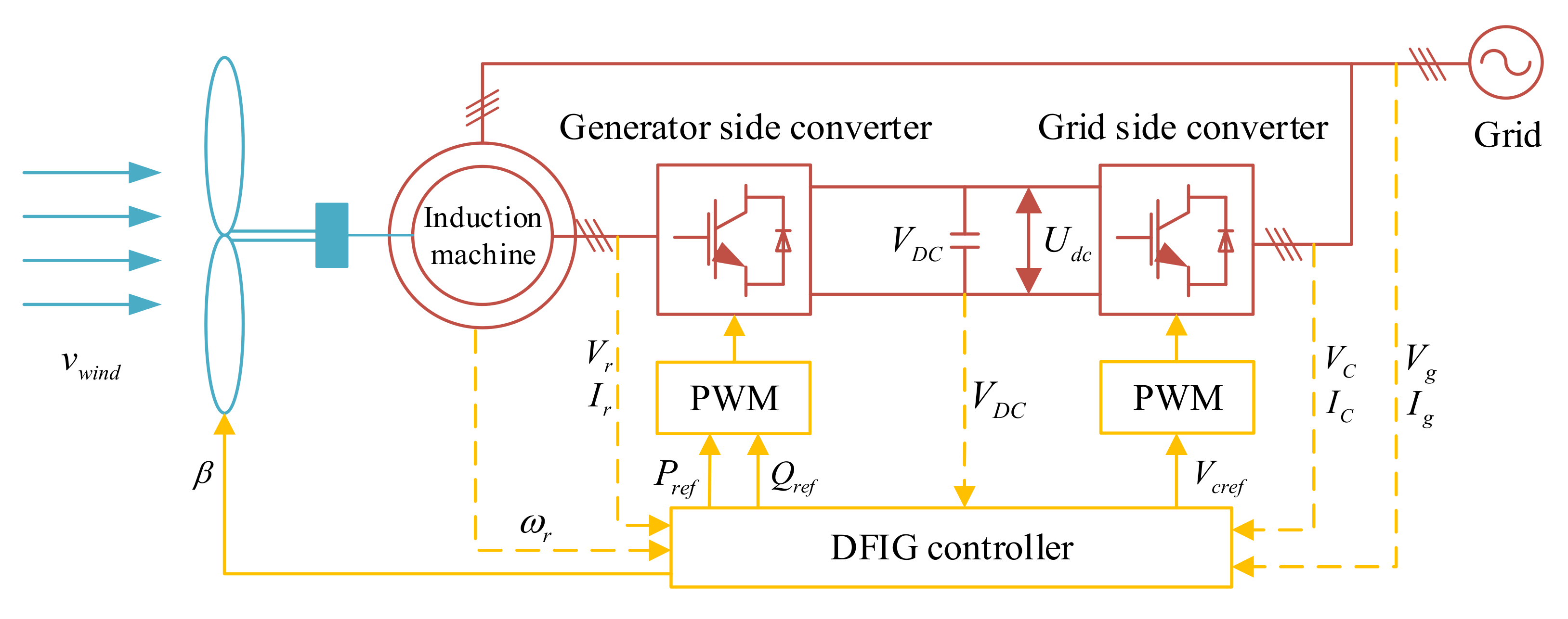
Figure 1 shows the diagram of the traditional DFIG-based wind turbine, which is composed of doubly fed induction machine, rotor side converter, grid side converter, DFIG controller, and power grid. The rotor side converter and grid side converter can decouple DFIG from power grid and perform variable speed operation.
The power converter is enabled by control system to perform the following functions. (1) To implement the maximum power point tracking when the wind speed is lower than the rated wind speed. (2) To maintain the DC-link voltage of power converter. (3) To provide the reactive power support in the presence of grid faults.
The mechanical power extracted from wind turbine can be represented as (1) [17,18].
where Pm is the mechanical power extracted from the wind energy by the wind turbines, ρ = 1.22 kg/m3 is the air density in kilograms per cubic meter, R is the turbine radius, ω is the turbine angular speed, v is the wind speed, λ is the blade top speed ratio, and the λ = ωR/v. β is the blades pitch angle, and Cp(λ,β) is the power performance coefficient of the turbine, wherein its value is related to the blades pitch angle and the blade top speed ratio, which can be represented as (2):
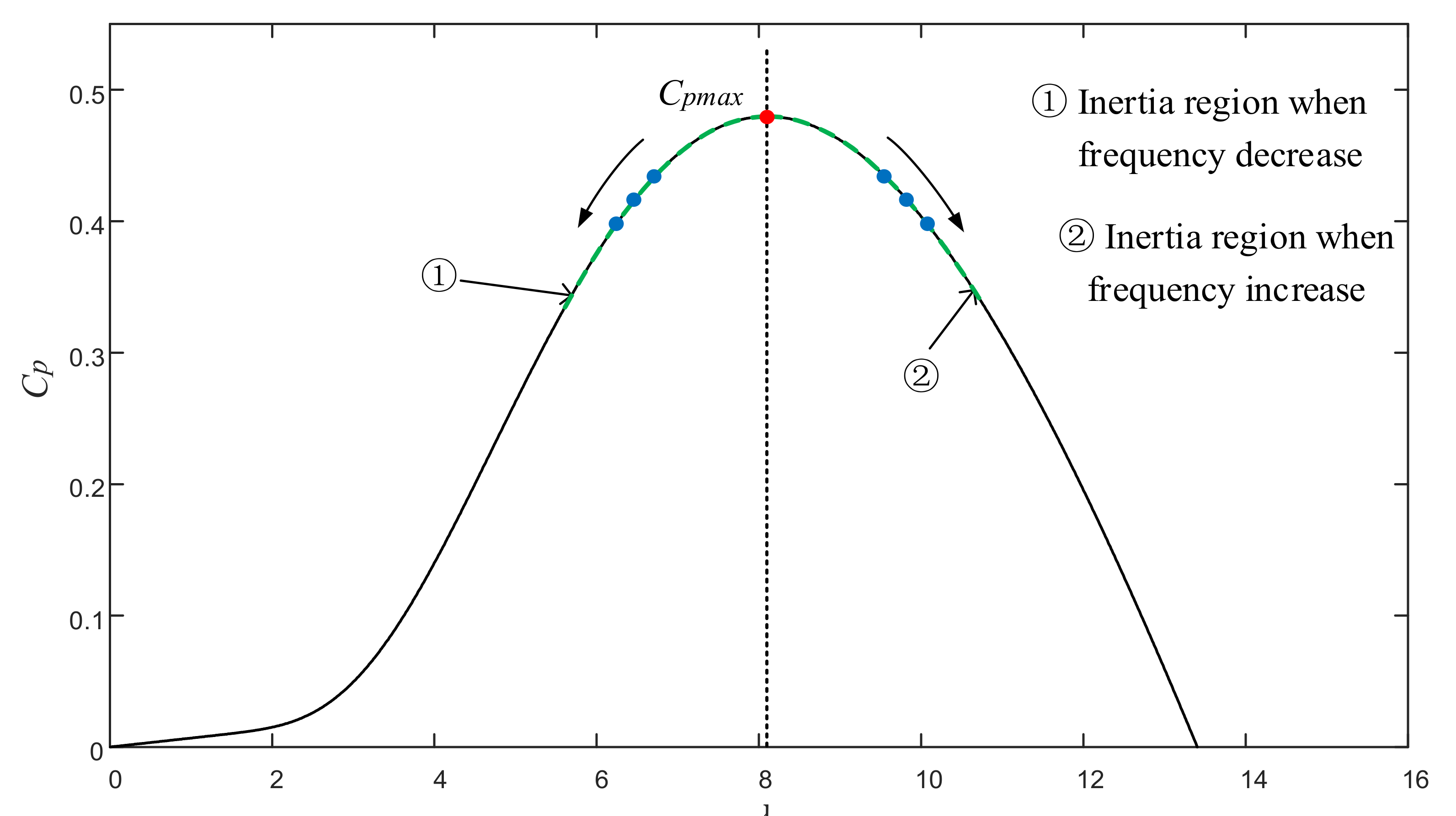
In order to make the Cp(λ,β) reach the optimal value Cpmax(λ,β), the rotor speed of the DFIG is controlled by wind power converter to capture the optimal tip speed ratio λopt. The wind turbine parameter values provided by the wind turbine supplier and related documents [19] can be used to obtain the relationship between the wind energy utilization coefficient, the tip speed ratio, and the pitch angle at the optimal operating point of the wind turbine. In order to analyze the influence of virtual inertia on the wind turbine, this paper mainly analyzed the influence of virtual inertia control on Cp and λ when the pitch angle is near zero. Figure 2 shows the relationship curve between tip speed ratio and wind energy utilization coefficient when β = 0°. It can be seen that the maximum value of wind energy utilization coefficient is Cpmax ≈ 0.48 when the blade tip speed ratio reaches the maximum value, and the optimal value of blade tip speed ratio is λopt ≈ 8.1. At this time, the wind energy utilization factor is the highest. When the gird load suddenly increases, the system frequency will decrease. Then, the rotational speed of wind turbine is reduced to release the kinetic energy of the rotor, where the wind turbine can be operated in region 1. At this time, the value of tip speed ratio λ will decrease. Therefore, Cp will decrease from the highest value Cpmax to the left along the curve of the relationship tip speed ratio and the wind energy utilization coefficient. On the other hand, when the gird load decreases, the system frequency will increase. Then, the rotational speed can be increased to support frequency regulation, where the wind turbine can be operated in region 2. At this time, the value of tip speed ratio λ will increase. Therefore, Cp will decrease from the highest value Cpmax to the right along the curve of the relationship tip speed ratio and the wind energy utilization coefficient.
The model of the wind energy conversion system with DFIG is described as follows:
where ψs is the stator flux, Ps is the stator active power, us is the stator voltage, is is the stator current, and ir is the rotor current. p is the differential operator, Ls is the stator inductance, Lm is the stator mutual inductance, ωs is the synchronous speed, and Rs is the stator resistance. Te is the electromagnetic torque of the motor and np is the pole-pairs number of the motor.
2.2. PD Virtual Inertia Controller
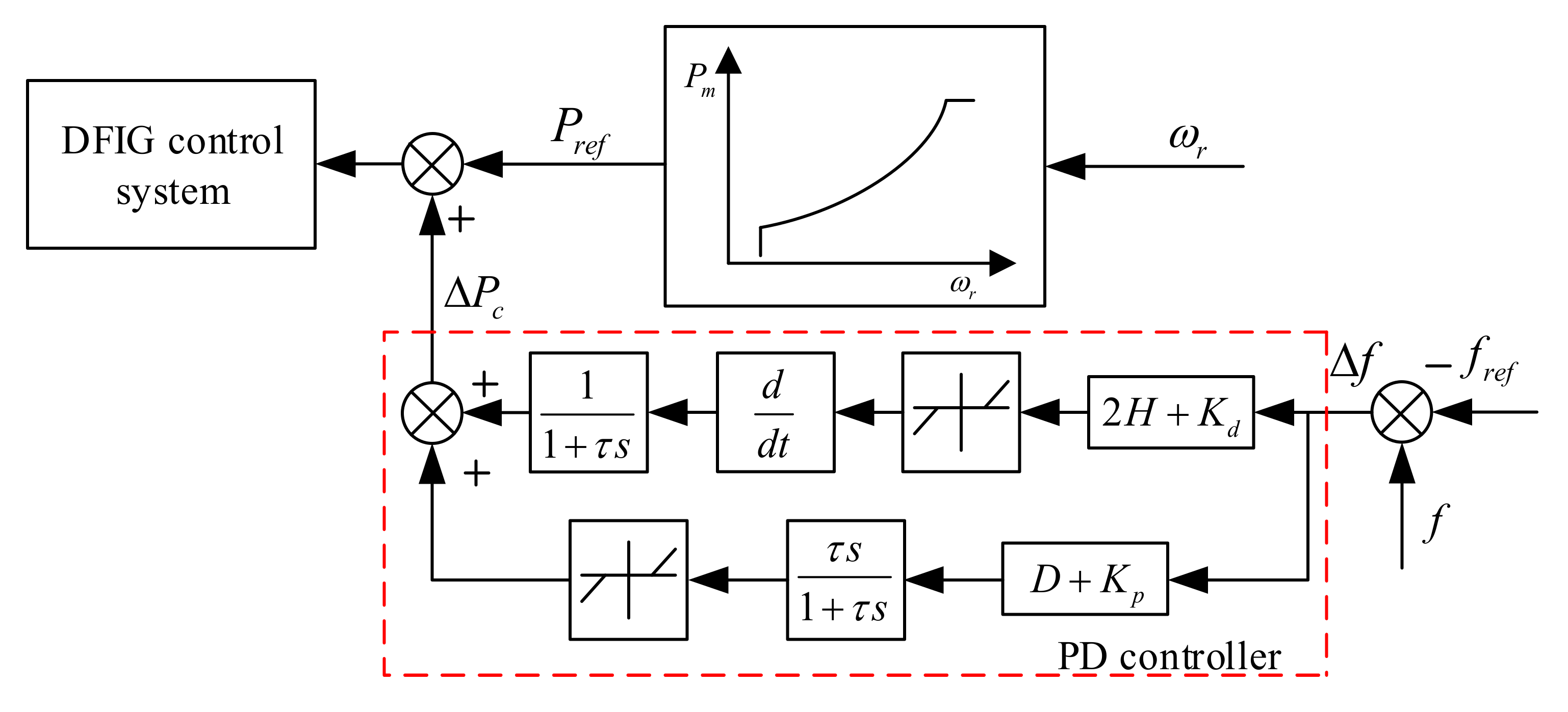
The wind turbine has the ability to adaptively address frequency response if a frequency power outer loop is added to the DFIG control system. Figure 3 shows the control structure. The power outer loop includes two parts: the proportional part acts on the dynamic frequency deviation (Δf), and the differential part acts on the frequency deviation change rate (dΔf/dt). In the initial stage when the power grid is out of balance, the system frequency responds quickly, and the differential part plays a major role at this time. When the system frequency drops or rises seriously, the proportional part will play a major role. The active power compensated to DFIG can be given as (4).
where Pc is the inertia response reference of active power, Kd is the differential parameter, Kp is the proportional parameter, Δf is the frequency offset, and dΔf/dt is the frequency rate.
In order to improve the transient performance of the system frequency, the equivalent inertia of the power system is increased by releasing the rotor energy storage and simulating the inertia response of the synchronous generator. The inertia response of the power system can be given as (5) [20].
where H is the inertia time constant, and D is the damping coefficient. Considering the inertia response of the wind turbine, the traditional PD virtual inertia control is given as (6).
It is easy to perform the PD-based virtual inertia control strategy in practical operation. However, the PD-based virtual inertia control strategy fails to provide more effective inertia support according to specific conditions in actual wind power systems. In (5), the frequency change rate measured from the power grid is susceptible to the effect of measurement noises. These measurement noises are, in the majority, caused by aging and parameter drift of measuring equipment and/or the difference of electromechanical characteristics between different equipment, leading to the difference of frequency measurements [21]. Due to the existence of measurement noise in the process of grid frequency measurement, the DFIG inertia emulation system has stronger uncertainty, and therefore it is urgent to develop an accurate DFIG inertia emulation system and to address the frequency change rate measurement noise so as to improve control effect of virtual inertia. To address the above problems, this paper presents a data-driven optimal control strategy for inertia emulation control.
3. Data-Driven Virtual Inertia Control Method
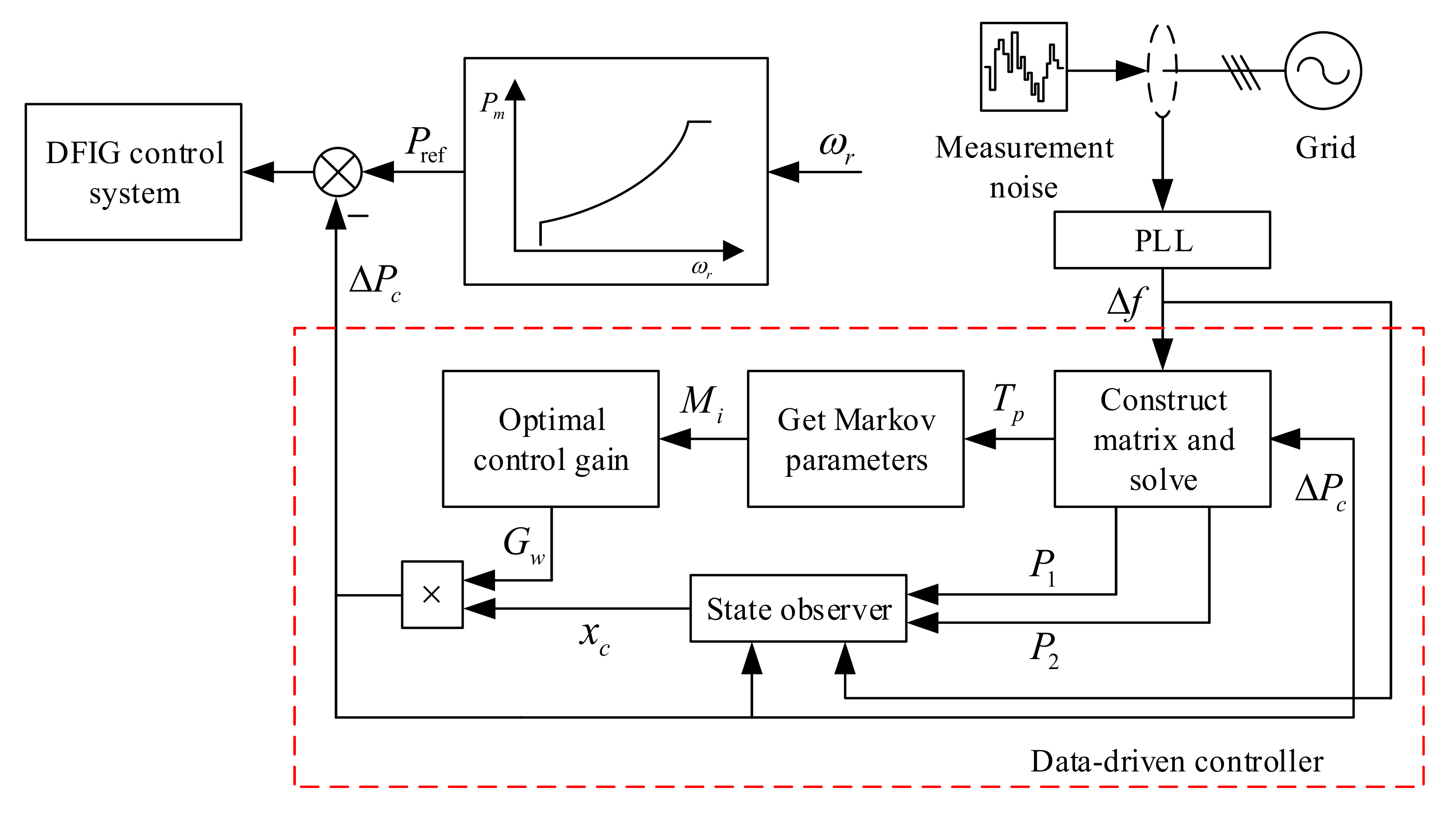
In this section, a data-driven virtual inertia control method is developed to perform inertia control. Figure 4 shows the diagram of data-driven inertia emulation controller, which is composed of state observer and the optimal controller based on the system Markov parameters. In this proposed inertia controller, a data-driven state observer based on the Markov parameters of the system is established, which can effective solution to estimate the state vector xc(k) of the optimal controller [22,23]. Then, the optimal controller of the inertia emulation system is designed through the closed solution of the differential Riccati equation with self-correction capability.
3.1. Description of the Optimal Problem
The power reference value Pref in the wind turbine control system are changed by traditional virtual inertia control, which makes the DFIGs show controllable inertia response characteristics when the system frequency fluctuates. In order to improve the inertia control performance, a data-driven inertia control method is proposed in this paper. The DFIG inertia emulation system at time k can be given in a state-space form as (7).
where x(k) is the n-dimensional state vector, u(k) is the m-dimensional control input vector, and y(k) is the l-dimensional measurement output vector. A, B, C are the parameter matrix. Then, the LQ optimal control is used to solve the control function.
The performance index function is given as (9).
where Q is a positive semi-definite symmetric weight matrix and R is a positive definite symmetric weight matrix.
When the state space model is unknown, the Markov parameter Mi can be obtained by using the online input and output data. In addition, the appropriate weights QW and RW are selected to solve the optimal control function as shown in (8), which can be given as (10).
where u is input vector of the DFIG inertia emulation system that is the grid frequency deviation Δf, and it is also the output of the wind power control system. y is output vector of the DFIG inertia emulation system that is the compensated active power ΔPc, and it is also the input of the wind power control system. QW is positive semi-definite symmetric weight matrix, RW is positive definite symmetric weight matrix, Mi = CA(i−1)B; Mi is the Markov parameter of the wind energy conversion system, where i = 1, 2, …, n.
The optimal control function is obtained by solving (11)
to reach the minimum. Therefore, the DFIG inertia emulation system can make the frequency f accurately track the rated value fN when the power supply load is unbalance so as to provide the inertia support.
3.2. Data-Driven Algorithm
The state vector of the DFIG inertia emulation system for p(p > 0) times can be obtained as (12).
where up(k) and yp(k) are respectively derived from u(k) and y(k), starting at first p-step input and output data form a column vector as (13) and (14).
The matrix Bp in (12) is an n × pm controllability matrix, Op is a pl × n observability matrix, and Tp is a pl × pm Toeplitz matrix of the system Markov parameters, where
Lemma 1.
[24] Assuming that the observable system model, the controllable matrix Bp and the diagonal constant matrix Tp are known; as long as pm ≥ n, there is a matrix M makes Ap + MOp = 0 holds.
Applying Lemma 1, (12) can be estimated by input and output as (15).
where
In order to obtain Markov parameters of the data-driven system, the input and output data column vectors are formed into matrices Y and V in the form of (16) and (17), and the relationship equation between the input and output data can be given as (18) [25].
P1, P2, and matrix Tp can be obtained by solving (18). When p = N + 1, the Markov parameter Mi = CA(i−1)B of the DFIG inertia emulation system can be extracted from Tp.
Lemma 2.
[26] The closed solution formula of the difference Riccati equation is given as (19).
where
R(k) = diag (R, R,⋯, R) and Q(k) = diag (Q, Q,⋯, Q) are both N − k + 1 dimensional matrices.
For the inertia emulation system with given Markov parameters, the closed solution of the differential Riccati equation is introduced. Applying Lemma 2, the data-driven controller is given as (20).
where Gw(k) is the gain of data-driven controller, and xc(k) is the state vector of data-driven controller, which can be given as (21) and (22).
where
S(N) = 0, and R(k + 1) = diag (RW, RW,⋯, RW) and Q(k + 1) = diag (QW, QW,⋯, QW) are both N − k dimensional matrices.
3.3. State Vector Estimation
In (22), the state vector xc(k) of the optimal controller based on data is related with A, C, and the state variable x(k). In the case of unknown system model, this paper presents a new method to construct a state observer to estimate xc(k), which can be estimated by taking the state vector x(k) of (15) into (22) when p = N + 1.
xc(k) is the column vector of from row l + 1 to row l(n − k + 1), so that the state vector of the data-driven optimal controller can be estimated by the input and output vectors and P1 and P2.
3.4. Self-Correction of the State Observer under Measurement Noise
To improve the robustness of control system with immunity to measurement noises in practical operation, the control system with capability of anti-interference and noise reduction is developed in this section. The measurement noise is emulated by adding random noise signals, which is introduced into Riccati equation and the data-based state observer. In addition, system frequency is measured by the phase-locked loop. Then, an optimal controller with self-correction ability under correlated noise is developed. The DFIG inertia emulation system with measurement noise can be given as (24).
where ω0(k) and v(k) are the input noise and measurement noise, respectively, and Ap, Op, and Γ are the state transition matrix, measurement matrix, and input noise matrix, respectively, which contain the unknown parameter vector θ.
Assuming that ω0(k) and v(k) are the correlated white noises with zero mean, variances Q0 and R, and correlated matrix S, then (25) can be obtained.
where E represents mathematical expectation, and T represents transpose.
When the θ is known, (24) can be represented as (26).
where, take J = ΓSR−1, and define:
and (26) can be represented as (27).
Then, white noise ω(k) is defined as (28).
(27) is transformed into (29).
and the variance of ω(k) is Q = Q0-SR−1ST.
In this way, (22) is rewritten as (30).
When p = N + 1, xc(k) can be obtained by taking (30) into (21).
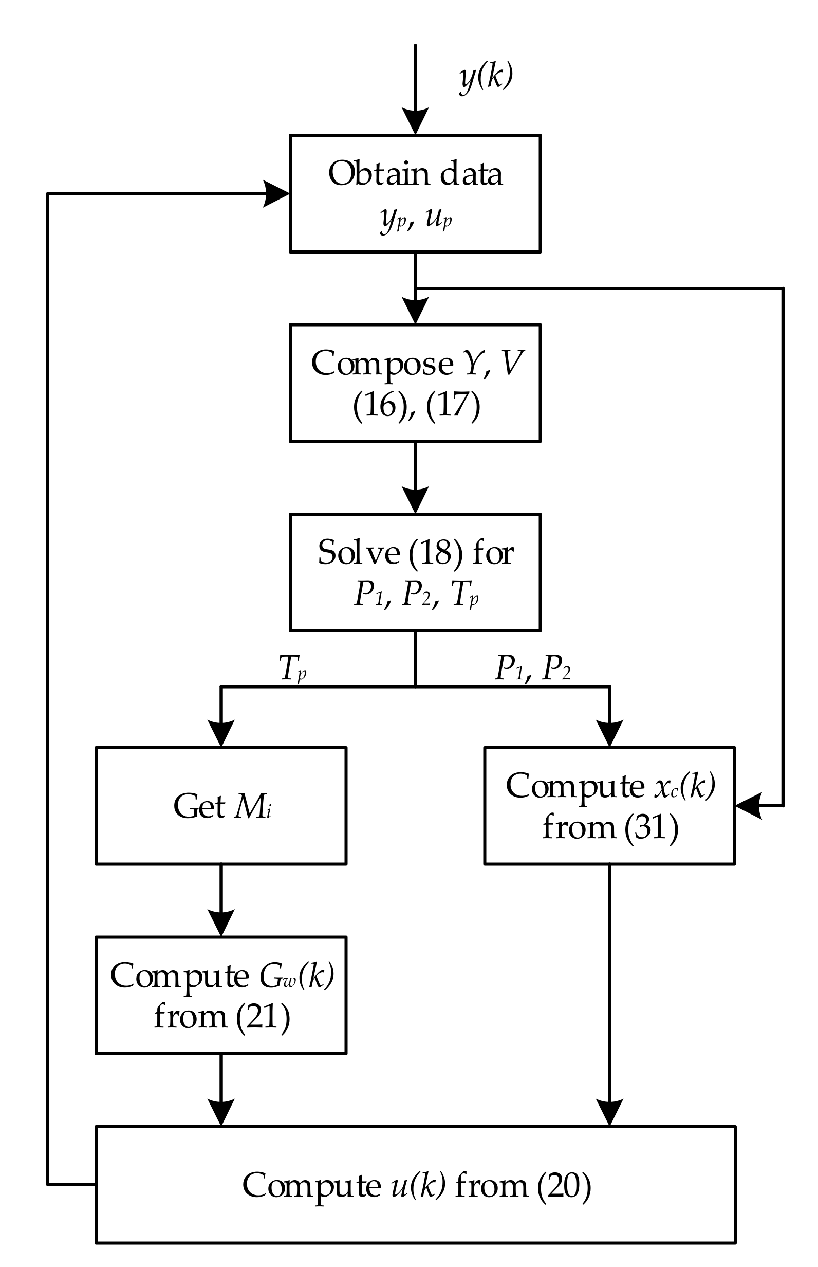
3.5. Algorithm Flow of Markov Riccati Controller
Figure 5 shows the flowchart of the proposed data-driven inertia control algorithm. When the data-driven controller is integrated into the DFIG inertia emulation system, the input and output data are collected to construct matrix Y and V. In order to obtain the accurate Markov parameters, the rows related to input vector in V must be linearly independent. Therefore, when selecting the length L of the data, it is necessary to ensure that the obtained data set is sufficient. The specific algorithm flow is given as follows.
- (1)
- The matrix Y and V is formulated by system output data and control input data collected in DFIG system according to (16) and (17).
- (2)
- The P1, P2, and matrix TP are obtained by solving (18). Then, the Markov parameters Mi (i = 1, 2,⋯, n) of DFIG inertia emulation system is obtained from TP by taking p = N + 1.
- (3)
- A set of data-based control gains Gw(k) is derived by substituting Mi into (21).
- (4)
- The estimated value of state vector is obtained by substituting P1, P2, and related input and output data into (31), and the state vector xc(k) of optimal controller is obtained by taking the estimated value of state vector’s second row to (n − k + 1)l row column vector.
- (5)
- The control input u(k) is calculated according to (20).
- (6)
- The new output data y(k) is obtained by taking the control input u(k) into wind power system, and the next moment state vector xc(k + 1) could be estimated by substituting the new control input u(k) and system output y(k) into Equation (31); then, the next moment control input u(k + 1) is obtained, which is cycled in turn.
4. Simulation Verification
In order to validate the effectiveness of the proposed data-driven inertia control method, we established a simulation model of a 1.5 MW DFIG-based wind turbine in Matlab/Simulink. The parameters of the system model are given in Table 1. Considering simulation time and accuracy of the model [27], we chose the length of the control horizon as N = 8, p = N + 1 = 9, and L = 3p + 10 = 37. Moreover, considering the switching loss of power converter, we chose the sampling period of PWM in power converter as T = 100 us [28,29]. Since the control bandwidth of the proposed data-driven controller is within the control bandwidth of the DFIG power controller, it thus can be implemented in the existing DFIG power controller with same sampling time. In addition, the dead band and filters were installed in the data acquisition link of the data-driven controller, where they aimed to filter out invalid signals.
The inertia emulation ability of wind turbine is important to provide inertia response similar with synchronous generators to reduce the frequency change rate of the system in the presence of frequency event. Therefore, under the condition of 11 m/s wind speed, the simulation study investigated the transient inertia support capability of the proposed control method under three different conditions, namely, system frequency decrease, system frequency increase, and system frequency decrease with measurement noises. In order to validate the advantages of the proposed method, we provided the comparative analysis to investigate the frequency regulation performance among three control methods under the same conditions.
NO Inertia Control: DFIG was operated without inertia emulation capability.
PD Inertia Control: DFIG was operated with PD-based inertia control to provide transient inertia support.
The proposed data-driven inertia control: DFIG was operated with the proposed inertia controller to provide transient inertia support.
4.1. Case I: System Frequency Decrease
When the system frequency deviation is higher than 0.03 Hz, the proposed virtual inertia control method is activated. The specific calculation process of the controller is given as follows. According to the sampled data, we can obtain the Markov parameters of the inertia emulation system.
According to step (3), a set of control gain Gw(k) (k = 1, 2,⋯, 8) is obtained as follows:
According to step (4), the first state vector is obtained as follows:
According to step (5), Gw(k) and xc(k) are multiplied to obtain the control input ΔPc:
The next moment input is obtained by taking the calculated ΔPc into the DFIG power compensation system, and cycle in turn. The specific simulation results are shown in Figure 6.
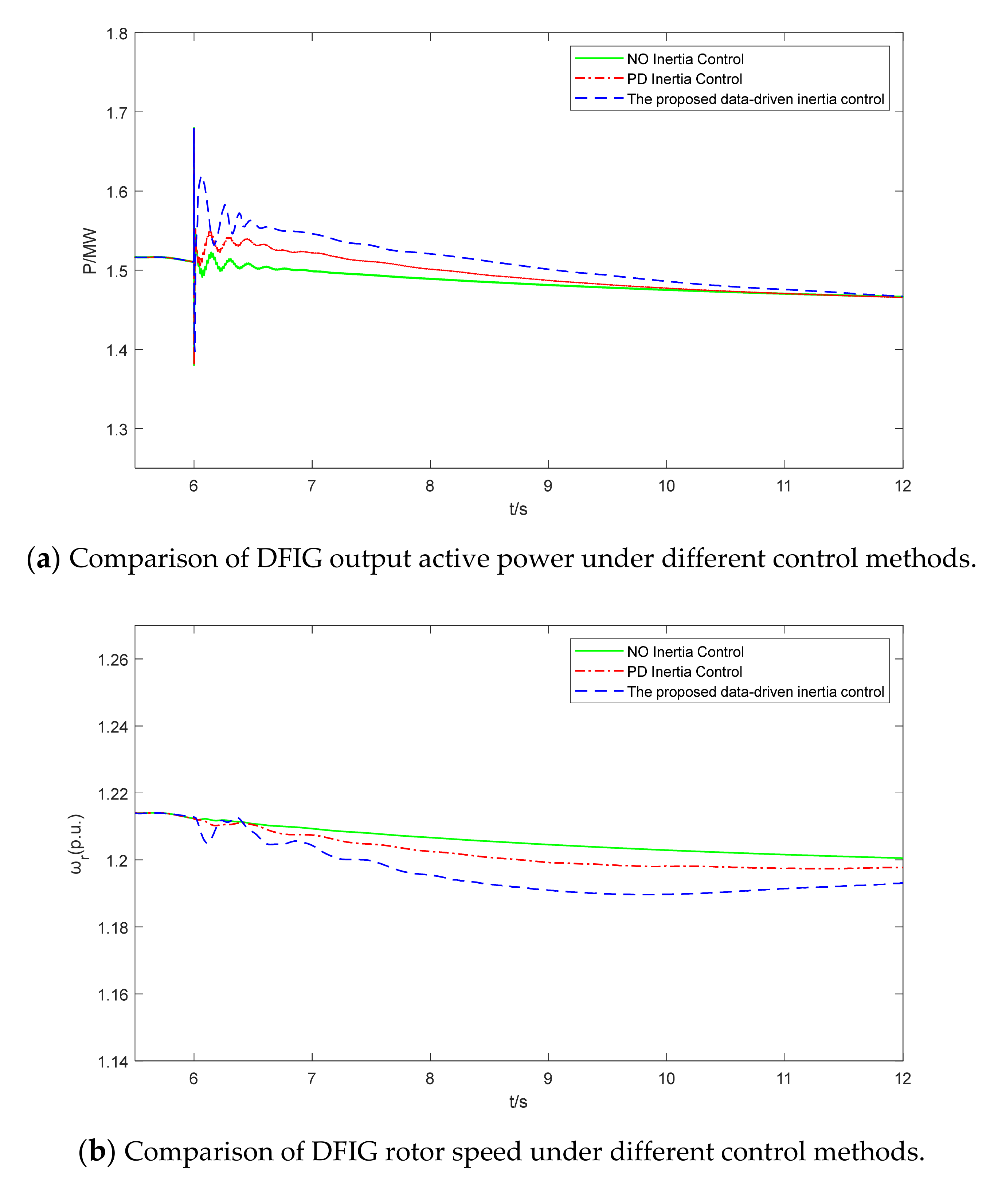
Figure 6a shows the comparative analysis of DFIG output active power under different control methods when system frequency decreases. It can be seen that the output active power of PD inertia control and the proposed data-driven inertia control was higher than that of NO inertia control. The active power was increased by DFIG by reducing the rotational speed.
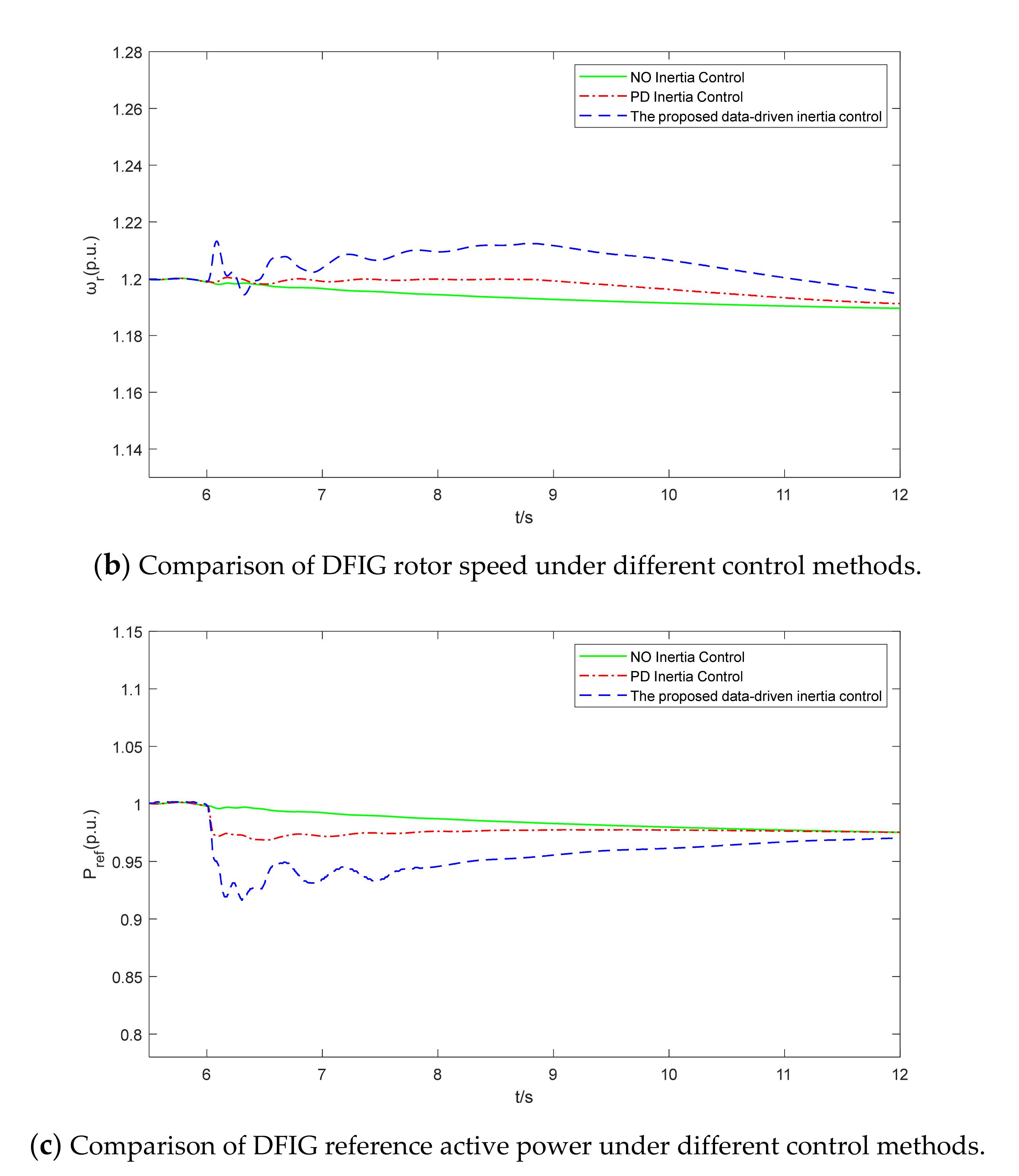
Figure 6b shows the comparative analysis of DFIG rotor speed under different control methods when system frequency decreased. It can be seen that the rotational speed of wind turbine was reduced, so as to release the rotational kinetic energy and provide inertia support for power system.
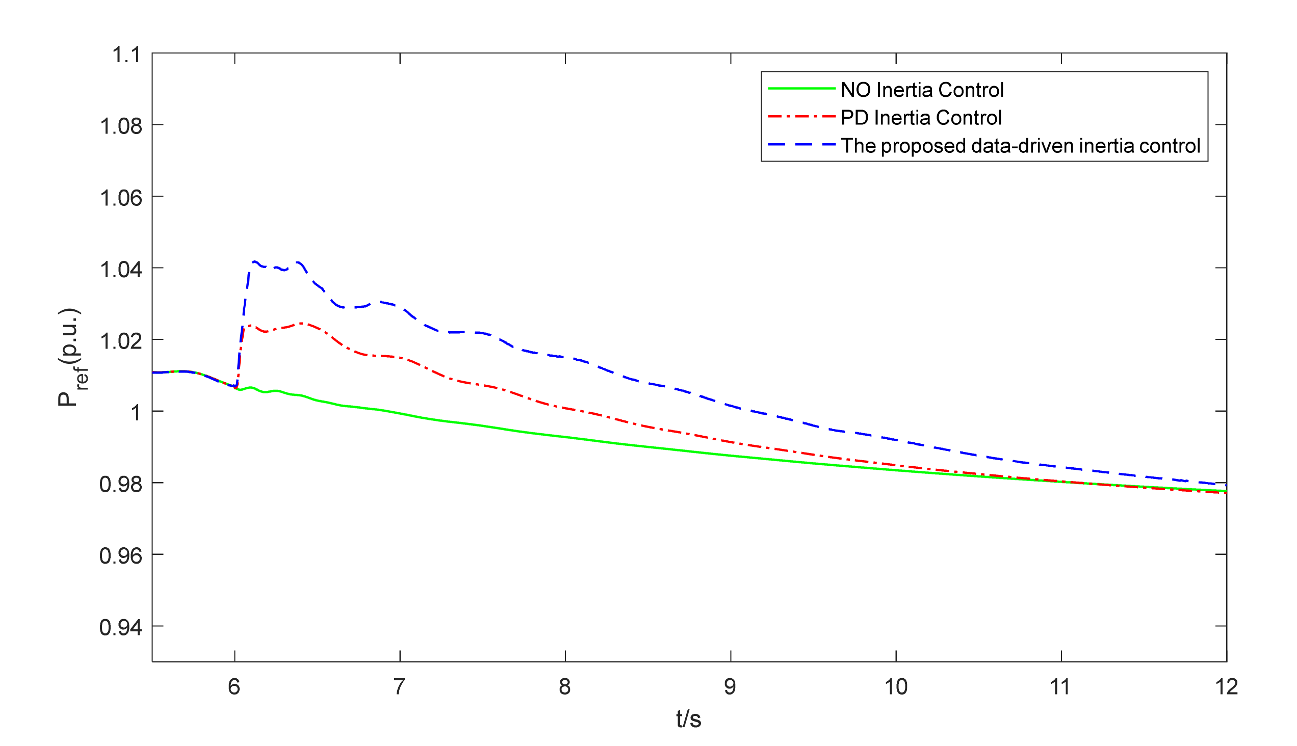
Figure 6c shows the comparative analysis of DFIG reference active power under different control strategies when system frequency decreased. It can be seen that the active power reference of inertia control under the proposed data-driven inertia control and PD inertia control was increased to provide inertia support for power system.
Simulation results showed that compared with PD inertia control, the proposed data-driven inertia control method was able to activate more kinetic energy, which thus provided effective inertia supports for the power grid.
4.2. Case II: System Frequency Increase
When the system frequency deviation is higher than 0.03 Hz, the data-driven virtual inertia controller is activated. Figure 7 shows the simulation results regarding this case.
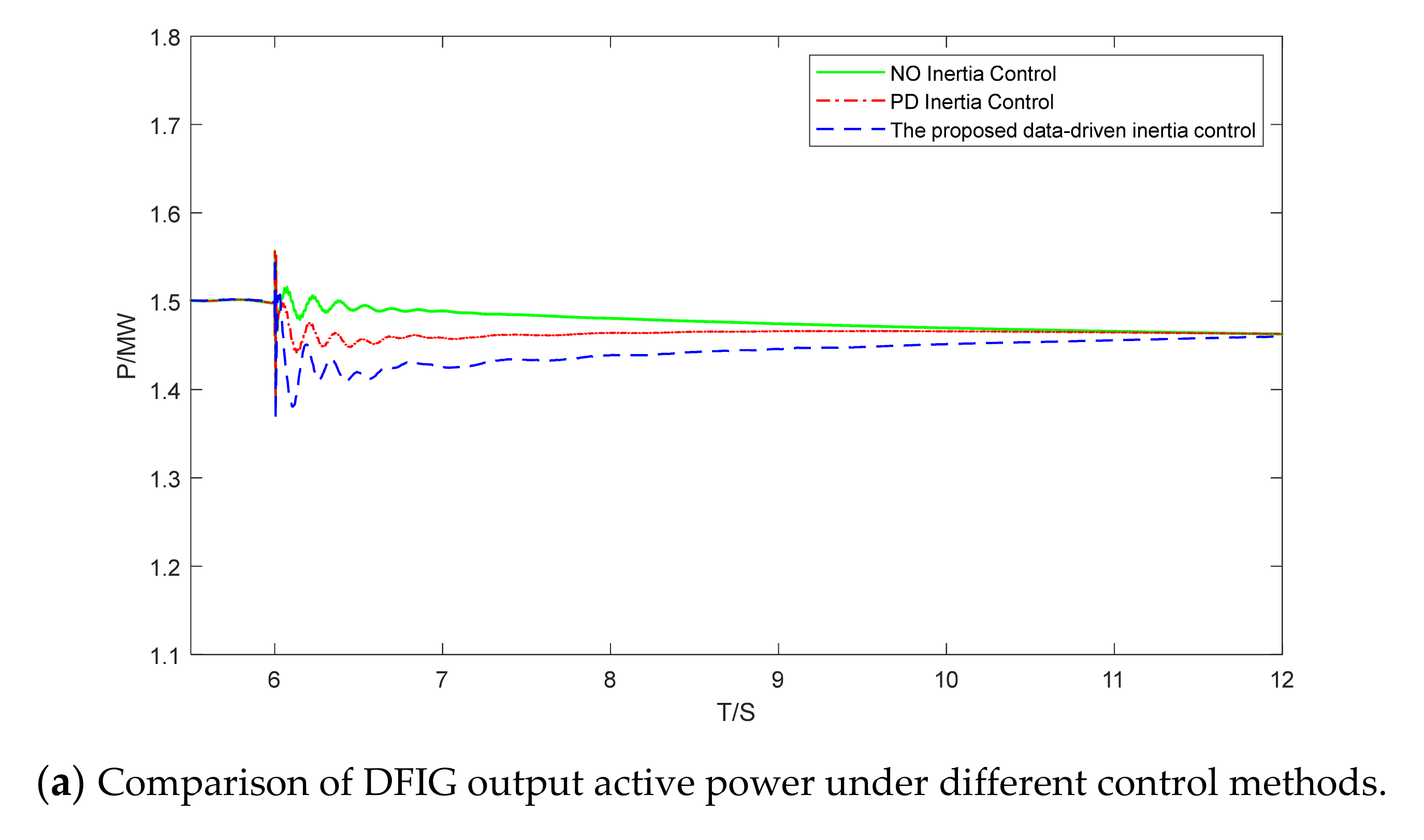
Figure 7a shows the comparison of DFIG output active power under different control methods when system frequency increased. It can be seen that the output active power of PD inertia control and the proposed data-driven inertia control was lower than that of NO inertia control.
Figure 7b shows the comparison of DFIG rotor speed under different control methods when system frequency increased. It can be seen that compared with PD inertia control, the use of proposed data-driven inertia control can effectively increase the rotor speed of DFIG, thereby suppressing the output power of DFIG and providing inertia support for the power system.
Figure 7c shows the comparison of DFIG reference active power under different control strategies when system frequency increased. It can be seen that the reference active power of the inertia control under the proposed data-driven inertia control and PD inertia control were reduced after system frequency increased, which in turn affected the DFIG rotor speed and provided inertia support for the power system.
Simulation results showed that when system frequency increased, the proposed data-driven inertia control method can contribute to transient frequency stability by increasing rotational speed of wind turbine.
4.3. Case III: System Frequency Decrease with Measurement Noise
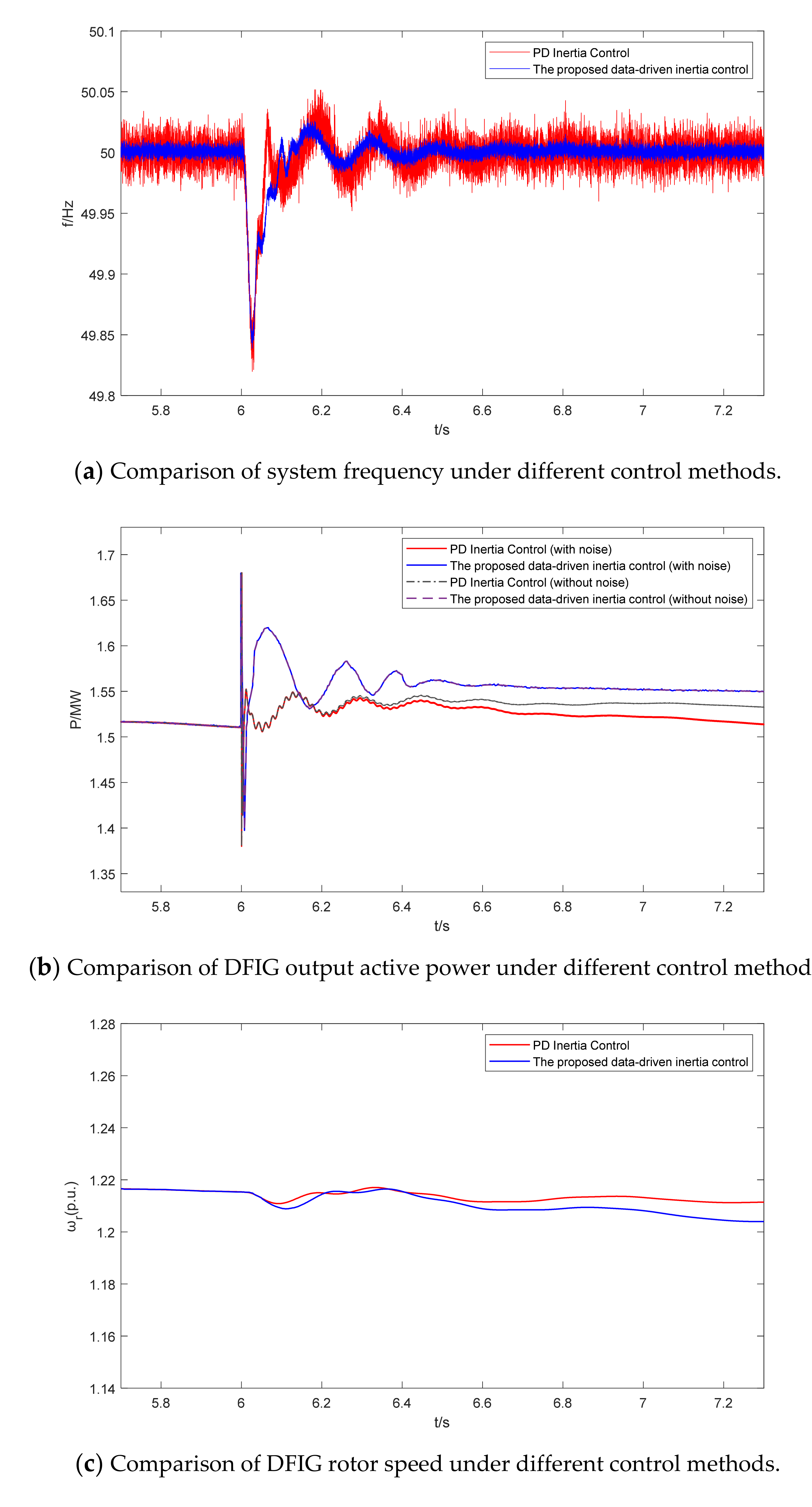
The aim of this case was to investigate the anti-interference ability of inertia emulation controller with measurement noises, thus NO inertia control strategies were not related with this issue. To emulate the measurement noise, we added a noise signal with a random fluctuation range of ±0.02 to the measured frequency feedback signal to simulate the noise amplification effect of frequency sampling in the DFIG system. When the system frequency deviation is higher than 0.03 Hz, the data-driven virtual inertia control method is activated. Figure 8 shows the simulation results.
Figure 8a shows that the comparison of system frequency under different control methods in the presence of noise and system frequency decreases. It can be seen that the performance of the PD inertia control was significantly affected by measurement noise, which caused the system frequency fluctuation from 50 to 49.82 Hz with obvious glitches. When the control method was the proposed data-driven inertia control, the system frequency drop was relatively improved compared with PD inertia control, and it was decreased from 50 to 49.85 Hz with slightly smaller glitches. After the data-driven virtual inertia control method was adopted, the lowest point of frequency drop was only 0.02 Hz lower than the case without noise signal.
Figure 8b shows the comparison of DFIG output active power under different control methods in the presence of noise and system frequency decreases. When the system had measurement noise, the inertial response speed and active power output of PD inertia control appeared to be weakened.
Figure 8c shows the comparison of DFIG rotor speed under different control methods in the presence of noise and system frequency decreases.
Simulation results showed that when system frequency decreased with measurement noise, compared with the traditional PD inertia control, the proposed data-driven inertia control method can provide effective inertia support to the power grid in the presence of measurement noise. Moreover, the rotational speed of wind turbine and active power output were merely affected by measurement noise.
5. Conclusions
This paper presents a novel data-driven virtual inertia emulation method to provide the transient inertia supports for power grid in the presence of frequency events. In this proposed inertia controller, a data-driven state observer based on the Markov parameters of the system was established. Then, the optimal controller of the inertia emulation system through the closed solution of the differential Riccati equation with self-correction capability was developed. Compared with traditional inertia emulation methods, the proposed method is able to adaptively adjust the active power output of DFIG through the real-time input and output data of the system. Moreover, the developed controller has good robustness, allowing it to reject the effects of measurement noise. The simulation results show that the proposed data-driven inertia emulation method can effectively provide the transient inertia support for power grid under different operation conditions, which further contributes to the stability and security of the power grid in the presence of frequency events.
Author Contributions
Conceptualization, T.L., L.W. and Y.W.; methodology, T.L. and L.W.; software, L.W.; validation, T.L., L.W. and Y.W.; formal analysis, T.L. and Y.W.; investigation, G.L., L.Z. and Z.J.; resources, Z.Z., G.L. and Z.J.; data curation, L.W.; writing—original draft preparation, L.W.; writing—review and editing, Y.W. and T.L.; visualization, Y.W.; supervision, Y.Z.; project administration, T.L. All authors have read and agreed to the published version of the manuscript.
Funding
This research was funded by ‘Jiangsu Huineng Electric Co., Ltd. and Jiangsu Province Postdoctoral Science Foundation under Grant No.2018K011B’ and ‘Science and Technology Innovation Team of Jiangsu University of Science and Technology’.
Conflicts of Interest
The authors declare no conflict of interest.
References
- He, Z.; Xu, S.; Shen, W. Overview of the development of the Chinese Jiangsu coastal wind-power industry cluster. Renew. Sustain. Energy Rev. 2016, 57, 59–71. [Google Scholar] [CrossRef]
- Liu, C.; Deng, F.; Heng, Q.; Cai, X.; Zhu, R.; Liserre, M. Crossing Thyristor Branches-Based Hybrid Modular Multilevel Converters for DC Line Faults. IEEE Trans. Ind. Electron. 2021, 68, 9719–9730. [Google Scholar] [CrossRef]
- Yang, D.; Kim, J.; Kang, Y.C. Temporary Frequency Support of a DFIG for High Wind Power Penetration. IEEE Trans. Power Syst. 2018, 33, 3428–3437. [Google Scholar] [CrossRef]
- Li, J.; Hu, Z.; Wang, Y.; Chen, Z. H14 Three-Level Inverter for Common-Mode Voltage Suppression. IEEJ Trans. Electr. Electron. Eng. 2021, 16, 315–323. [Google Scholar] [CrossRef]
- Technical rule for connecting wind farm to power system. GB/T 19963-2011. In National Electric Power Regulatory Standardization Technical Committee; China Standards Press: Beijing, China, 2011.
- National Grid (Great Britain) Company. The Grid Code. 2018. Available online: https://www.nationalgrid.com (accessed on 1 December 2018).
- Wu, Y.K.; Shu, W.H.; Hsieh, T.Y. Review of Inertial Control Methods for DFIG-Based Wind Turbines. Int. J. Electr. Energy 2015, 3, 174–178. [Google Scholar] [CrossRef] [Green Version]
- Gu, W.; Liu, W.; Wu, Z.; Chen, W. Cooperative Control to Enhance the Frequency Stability of Islanded Microgrids with DFIG-SMES. Energies 2013, 6, 3951. [Google Scholar] [CrossRef]
- Tian, X.; Wang, W.; Chi, Y. Variable parameter virtual inertia control based on effective energy storage of DFIG-based wind turbines. Dianli Xitong Zidonghua/Autom. Electr. Power Syst. 2015, 39, 33. [Google Scholar]
- Yuan, T.; Wang, J.; Guan, Y. Virtual Inertia Adaptive Control of a Doubly Fed Induction Generator (DFIG) Wind Power System with Hydrogen Energy Storage. Energies 2018, 11, 904. [Google Scholar] [CrossRef] [Green Version]
- Gao, N.; Lin, X.; Sang, S. Modified Inertia Synchronization Control for a Type-IV Wind Turbine Integrated with a Battery Energy Storage Unit. J. Electr. Eng. Technol. 2021, 5, 1–9, accepted. [Google Scholar]
- Pradhan, C.; Bhende, C.N.; Samanta, A.K. Adaptive virtual inertia-based frequency regulation in wind power systems. Renew. Energy 2018, 115, 558–574. [Google Scholar] [CrossRef]
- Zhang, X.; Wang, Y.; Fu, Y. A novel method for obtaining virtual inertial response of DFIG-based wind turbines. Wind Energy 2016, 19, 313–328. [Google Scholar] [CrossRef]
- Liu, J.; Yang, Z.; Yu, J. Coordinated control parameter setting of DFIG wind farms with virtual inertia control. Int. J. Electr. Power Energy Syst. 2020, 122, 106607. [Google Scholar] [CrossRef]
- Guo, W.; Feng, L.; Si, J. Incorporating approximate dynamic programming-based parameter tuning into PD-type virtual inertia control of DFIGs. In Proceedings of the 2013 International Joint Conference on Neural Networks, Dallas, TX, USA, 4–9 August 2013. [Google Scholar]
- Jing, M.; Song, Z.; Zhang, Y. Robust Stochastic Stability Analysis Method of DFIG Integration on Power System Considering Virtual Inertia Control. IEEE Trans. Power Syst. 2017, 32, 4069–4079. [Google Scholar]
- Jia, F.; Cai, X.; Li, Z. Frequency-distinct control of wind energy conversion system featuring smooth and productive power output. IEEE Access 2018, 99, 16746–16754. [Google Scholar] [CrossRef]
- Papadimitriou, C.N.; Vovos, N.A. Transient Response Improvement of Microgrids Exploiting the Inertia of a Doubly-Fed Induction Generator (DFIG). Energies 2010, 3, 1049. [Google Scholar] [CrossRef] [Green Version]
- Lie, X.; Cartwright, P. Direct active and reactive power control of DFIG for wind energy generation. IEEE Trans. Energy Convers. 2006, 21, 750–758. [Google Scholar]
- Zhu, J.; Hu, J.; Hung, W. Synthetic Inertia Control Strategy for Doubly-Fed Induction Generator Wind Turbine Generators Using Lithium-ion Supercapacitors. IEEE Trans. Energy Convers. 2018, 33, 773–783. [Google Scholar] [CrossRef]
- Tsai, S.S.; Zhong, Z.A.; Zuo, J.; Liu, Y.L. Analysis of wide-area frequency measurement of bulk power systems. In Proceedings of the 2006 IEEE Power Engineering Society General Meeting, Montreal, QC, Canada, 18–22 June 2006. [Google Scholar]
- Wang, Y.; Chen, Z.; Wang, X. An Estimator-Based Distributed Voltage-Predictive Control Strategy for AC Islanded Microgrids. IEEE Trans. Power Electron. 2015, 30, 3934–3951. [Google Scholar] [CrossRef]
- Wang, Y.; Wang, X.; Chen, Z. Distributed Optimal Control of Reactive Power and Voltage in Islanded Microgrids. IEEE Trans. Ind. Appl. 2017, 53, 340–349. [Google Scholar] [CrossRef]
- Lim, R.K.; Phan, M.Q.; Longman, R.W. State-Space System Identification with Identified Hankel Matrix. Department of Mechanical and Aerospace Engineering Technical Report No. 3045; Princeton University: Princeton, NJ, USA, 19 September 1998. [Google Scholar]
- Aangenent, W.; Kostic, D.; Jager, B.D. Data-based optimal control. In Proceedings of the 2005 American Control Conference, Portland, OR, USA, 8–10 June 2005; pp. 1460–1465. [Google Scholar]
- Lewis, F. A generalized inverse solution to the discrete-time singular Riccati equation. IEEE Trans. Autom. Control 1981, 26, 395–398. [Google Scholar] [CrossRef]
- Xun, L.; Ji, Z. Data driven optimal control of wind energy conversion system. J. Nanjing Univ. Aeronaut. Astronaut. 2012, 44, 129–133. [Google Scholar]
- Wang, Y.; Wang, X.; Blaabjerg, F.; Chen, Z. Harmonic Instability Assessment Using State-Space Modeling and Participation Analysis in Inverter-Fed Power Systems. IEEE Trans. Ind. Electron. 2017, 64, 806–816. [Google Scholar] [CrossRef]
- Wang, Y.; Wang, X.; Blaabjerg, F.; Chen, Z. Small-Signal Stability Analysis of Inverter-Fed Power Systems Using Component Connection Method. IEEE Trans. Smart Grid 2018, 9, 5301–5310. [Google Scholar] [CrossRef] [Green Version]
Figure 1.
The diagram of DFIG-based wind turbine.

Figure 2.
Relationship curve between tip speed ratio and wind energy utilization coefficient when β = 0°.
Figure 2.
Relationship curve between tip speed ratio and wind energy utilization coefficient when β = 0°.

Figure 3.
Additional power outer loop for inertial emulation control.

Figure 4.
The diagram of data-driven inertia controller for DFIG-based wind turbine.

Figure 5.
The flowchart of the proposed data-driven inertia control algorithm.

Figure 6.
Simulation results of power system when frequency decreased.


Figure 7.
Simulation results of power system when frequency increased.


Figure 8.
Simulation results of power system when frequency decreased with measurement noise.


Table 1.
Simulation parameters of DFIG-based wind turbine.
| Parameter | Value |
|---|---|
| Air density, ρ | 1.22 kg/m3 |
| DFIG rated voltage, Veref | 575 V |
| DFIG rated power, Peref | 1500 kW |
| Inertia of generator, Hg | 0.685 s |
| Wind turbine inertia constant, HWT | 4.32 s |
| Magnetizing inductance, Lm | 2.9 (p.u.) |
| Stator self-inductance, Ls | 0.18 (p.u.) |
| Rotor self-inductance, Lr | 0.16 (p.u.) |
| Rated wind speed, vr | 11 m/s |
| Sampling time of data driven controller, T | 0.00001 s |
| QW | 1 |
| RW | 0.0001 |
| N | 8 |
| p | 9 |
| L | 37 |
Publisher’s Note: MDPI stays neutral with regard to jurisdictional claims in published maps and institutional affiliations. |
© 2021 by the authors. Licensee MDPI, Basel, Switzerland. This article is an open access article distributed under the terms and conditions of the Creative Commons Attribution (CC BY) license (https://creativecommons.org/licenses/by/4.0/).
Share and Cite
MDPI and ACS Style
Li, T.; Wang, L.; Wang, Y.; Liu, G.; Zhu, Z.; Zhang, Y.; Zhao, L.; Ji, Z. Data-Driven Virtual Inertia Control Method of Doubly Fed Wind Turbine. Energies 2021, 14, 5572. https://0-doi-org.brum.beds.ac.uk/10.3390/en14175572
AMA Style
Li T, Wang L, Wang Y, Liu G, Zhu Z, Zhang Y, Zhao L, Ji Z. Data-Driven Virtual Inertia Control Method of Doubly Fed Wind Turbine. Energies. 2021; 14(17):5572. https://0-doi-org.brum.beds.ac.uk/10.3390/en14175572
Chicago/Turabian StyleLi, Tai, Leqiu Wang, Yanbo Wang, Guohai Liu, Zhiyu Zhu, Yongwei Zhang, Li Zhao, and Zhicheng Ji. 2021. "Data-Driven Virtual Inertia Control Method of Doubly Fed Wind Turbine" Energies 14, no. 17: 5572. https://0-doi-org.brum.beds.ac.uk/10.3390/en14175572
Note that from the first issue of 2016, this journal uses article numbers instead of page numbers. See further details here.