1. Introduction
Large amounts of heat are wasted in industrial processes, so this energy recovery potential is large and unexplored. For instance, more than 20,000 TWh of thermal energy was wasted to the environment in the US in 2018 alone [
1]. The energy consumption of the cement industry is estimated to be about 2% of the worldwide primary energy consumption. Their processes are characterized by having a significant amount of heat losses mainly within the flue gases and the air stream used for cooling down the clinker. A heat recovery system could increase the efficiency of the cement plant as well as reduce the amount of CO
2 emissions to the environment by converting this energy to electricity. There is a plethora of methods for recovering waste heat, namely, through the use of thermodynamic cycles implemented with thermal engines, with the Organic Rankine Cycle (ORC) being a notable example [
2]. However, few systems are capable of operating nearly unattended and in a way that largely dispenses with maintenance costs. Thermoelectric generators (TEGs) are among the few systems that are able to convert heat directly into electricity with no moving parts and thus with hardly any maintenance needs. When a temperature gradient is applied across the junctions of two dissimilar thermoelectric (TE) materials, a voltage is created through the Seebeck effect [
3]. Conventional TEGs typically have low conversion efficiency (around 5% for medium temperature heat sources), low power density, often use rare and toxic elements (as in the case of bismuth telluride) and especially tend to display a high cost per unit power produced. This cost varies substantially with the application and the materials, but it easily surpasses 50 USD/We, when in order to be competitive with ORC it should be one order of magnitude lower [
4,
5]. This has so far limited their interest for large-scale Industrial Waste Heat Recovery (IWHR) applications. So, the question that rises is the following: could TEGs become viable for large-scale applications?
In industrial processes such as those found in the steel, ceramic or cement industries, heat is wasted abundantly. Therefore, maximizing power and the cost per unit power is generally preferred over the sole maximization of efficiency. Now, the geometry of TEGs is not normally optimized for power density and for scaling-up [
6]. The design of existing commercial thermoelectric modules is often optimized for cooling applications, which remain the main market for thermoelectrics [
7,
8].
There have been some investigations into large-scale TEG applications. It is worth mentioning the now extinct company Alphabet Energy’s E1 generator [
9]. It was a large-scale TEG capable of up to 25 kWe that was compacted into a single standard container, with only the radiators being at the outside. It was a turnkey solution to be attached to any heat source, such as large engine exhaust gases located in remote locations with difficult access to power supply [
9]. It had a modular design and proposed the use of the same silicide/tetrahedrite material combination that is proposed in the present study. Unfortunately, the company went bankrupt and the project was discontinued before it took off.
Researchers from Navarra, Spain [
10], have been assessing the potential for recovering Waste heat from industrial chimneys using TEGs and aiming at minimizing consumption from auxiliaries such as cooling pumps or blowers and using instead thermosiphons [
10]. They estimated the maximum net production to be around 45 kWe for their application, with investment costs of around 10 EUR/We.
Yazawa et al. [
11] assessed a thermoelectric generator for the glass industry using a generic material with
zT = 1 and using the 1500 °C temperature of the process in an effective way. They predicted 55.6 kWe with an efficiency of over 15% from a 500 ton/day glass production system, estimating an additional cost of 1–2 USD/We. Yazawa et al. [
12] also assessed the benefit of having TEGs topping a steam turbine cycle given the temperature mismatch between the combustion and the vapour temperatures, which is not good in terms of thermodynamic irreversibilities. Again, a generic TE material with
zT = 1 or higher was envisaged. They concluded that TEGs that would indeed display this performance and withstand the temperatures at stake, could indeed improve energy savings.
Ebling et al. [
13] evaluated theoretically and experimentally a TEG to recover the heat from hot metal components after they finish the metal-forming process at 1300 °C. They measured nearly 400 We with 2.6% efficiency, with 50 modules being heated through radiation and convection by the components as they were transported through a conveyor belt.
Meng et al. [
14] theoretically assessed the recovery of an industrial gaseous waste heat flow with TEGs and predicted around 1.47 kWe/m
2 with a conversion efficiency of 4.5% for exhaust gas at 350 °C. They predicted a payback period of about 4 years.
Kuroki et al. [
15] installed a bismuth telluride TEG system in a continuous steel casting line in Japan to recover waste heat through radiative heat transfer. The output was around 9 kWe for a 4 m × 2 m TEG system located 2 m away from the slab, which had a temperature of around 1200 K and a width of 1.7 m. An application in the same field (radiative heat transfer from a continuous steel casting line) was assessed by Ghosh et al. [
16], who predicted an output of around 1.5 kWe/m
2 for a TEG located at a 2 m distance from a 1200 K hot steel slab.
Other studies included the one by Kristiansen et al. [
17], who assessed the waste heat recovery from a marine waste incinerator using TEGs and calculated an optimal production of 38 kWe at a price of 2.7 USD/We. The reason for such a low cost might be related to the fact that a generic material with an average
zT of 1 was used, the heat source temperatures were in excess of 1000 °C, with the TEG modules achieving operating temperatures of around 450 °C, which is out of the range that Bismuth Telluride modules can withstand (typically up to 250 °C).
Another marine application was the one assessed by Georgopoulos et al. [
18], who studied a TEG integrated into the marine scavenge air cooler heat exchanger of a very large crude oil carrier and obtaining 26 kWe of extra power per scavenge air cooler, which corresponded to 0.2% of the engine power output. Kanmohammadi and Saadat-Targhi [
19] assessed the implementation of a TEG integrated into the liquefied natural gas production process. Mirhosseini et al. [
20] analyzed the performance of a TEG applied to a rotating cement kiln using both bismuth telluride and zinc antimonide modules. The latter ones were projected to perform the best, with a projected production of around 0.25 kWe/m
2 and a return of investment of around 3.5 years, less than half of bismuth telluride. Another rotating Cement Kiln application was explored by Qi Luo et al. [
21], in which an array of TEGs attached to a secondary coaxial shell with the rotary kiln was predicted to be able to produce 212 kWe. Ishak et al. [
22] assessed the integration of a TEG into a biomass gasification system. The system was able to improve the energy efficiency in more than one percentage point and the exergy efficiency in 1.4%.
While the aforementioned studies point out the feasibility of IWHR TEGs with a careful design, most of these systems were either only simulated or were built on a small scale. Moreover, the estimated cost per unit power was often very high and requiring the use of rare or expensive materials. Moreover, the use of conventional modules in large applications would require millions of TE elements, solders, etc. Therefore, scaling up these systems would not reduce complexity, on the contrary. Thus, a paradigm shift in the way that TEGs are normally designed for large-scale TEGs seems to be needed to enable their viability. The aim of this work is the introduction of a new TEG concept suited for large-scale IWHR through the use of affordable materials and manufacturing/assembling processes, as well as geometries that may be suitable for large-scale systems.
The main novelty of the present work seems to be the large element geometry configuration, which has rarely been assessed, but which enables a series of strategies that are useful for large-scale, affordable TEG systems, described in continuation. Moreover, the materials used, developed recently by the authors [
23], are novel materials displaying low cost and attractive performance for their cost. The multiphysics analysis is also carefully performed. Namely, it incorporates the influence of hot and cold side heat exchangers and it is performed for real matched load conditions since the internal resistance of the system is updated during the iterative process. The multiphysics analysis enabled the extraction of the geometries that would be most oriented towards high power per pair, power density or efficiency, also with a balanced geometry being proposed.
2. Concept
Firstly, the TE materials used in large-scale IWHR need to be much cheaper than the currently ones (e.g., Bismuth Telluride) [
4,
24]. The authors have previously studied and established competitive conventional TE elements made of the materials developed in the project THERMOSS (p-tetrahedrite, n-magnesium silicide), which are proposed to be used in the new TEGs [
23]. They display prices of around 5 USD/kg, while Bismuth Telluride is at least 20 times more expensive, besides containing rare and toxic materials (e.g., tellurium) [
4].
The p-tetrahedrites and n-silicides have nominal compositions of Cu
11MnSb
4S
13 and Mg
2Si
0.57Sn
0.4Bi
0.03, respectively. Although the power factor is different between the two members (
Figure 1a),
zT is the same (
Figure 1b) due to the much lower tetrahedrite thermal conductivity [
23]. The difference in power factor (originated from electrical conductivity) hints that the optimal p- and n-type section areas will tend to be different. This stands as a main issue on the module design. Overall,
zT values are very promising, warranting further investigation at the level of module manufacture and application.
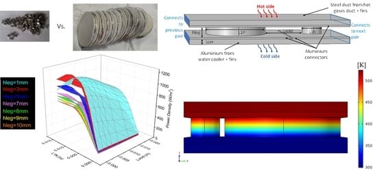
Next, a main aspect of the concept here proposed is to use larger element assemblies (
Figure 2), something that has rarely been done before, possibly because larger elements tend to yield lower voltages per unit power and higher currents. This might be a challenge for small systems, but not so much for larger ones. This large element configuration may allow for high power densities (We/m
2) and drastically reduces the degree of complexity of the assembly: there is a drastic reduction in the number of pairs, cuttings (dicing process), connections and solders per unit power and per unit area. The bigger scale of the elements and their spacing will also allow for much coarser manufacturing tolerances. Manufacturing cost is inversely proportional to tolerance, so this will allow for much simpler and much cheaper manufacture/assembly processes [
25]. Under these circumstances, dissimilar thermal expansion of the p- an n-elements will not be such a problem, as in the case of tightly packed small elements. Being large, the aluminium connectors will be able to more easily conform to the thermal expansions without creating the critical thermal stresses that would be much stronger in tightly packed small element modules. All these factors will favour an easier scalability (upscaling) of the concept. Moreover, the use of a round geometry may be advantageous to eliminate manufacturing processes, as many material manufacturing processes, such as hot press, already produce large round-shaped pellets that could be directly used as elements without the need for the element dicing process.
Next, a practical and affordable connection process is proposed, consisting of cheaper aluminium connectors instead of copper ones and using nickel or silver paints for electrical connection instead of solders, which would be easily upscalable (
Figure 3 displays an example of the copper and aluminium connectors that were successfully applied to the mentioned materials by the authors).
The connectors considered will be much broader than the elements, covering most of the heat source and heat sink surfaces. This way, each element can absorb/reject heat from/to a broader area to minimize thermal resistances, namely, thermal contact resistance. This is especially important in situations where the heat source or heat sink have a higher thermal resistance. Under these circumstances, using wider connectors will be a good strategy to decrease the thermal resistance [
26], as depicted in
Figure 4. For instance, since thermal resistance is inversely proportional to the heat transfer section area, in cases where the implementation of finned surfaces at the heat source would not be viable, the increase in the area of the connectors would allow one to maintain the thermal resistance at a reasonably low value, through the increase in the heat transfer area available per element. Such a strategy of using custom connector dimensions seems more feasible in large element module strips than in conventional small element modules.
Regarding the electrical insulation of the connectors, a cheap and thin electrically insulating, but thermally conductive, layer could be used instead of brittle and more expensive ceramic plates. Options may include ultrathin tape (<50 μm) of Kapton, mica or, maybe even better, graphite with electrically insulating adhesives [
27]. The estimation of the thermal resistance of such interfaces is described further ahead in this document.
Heat exchangers often make up for one of the most expensive portions of TEGs [
24]. A viable option would be to adapt existing extruded aluminium profiles such as the one displayed in
Figure 5 to be used as heat exchangers. These finned blocks are available commercially in various shapes. Since the cost of the aluminium extrusion process is mostly linked to the extrusion matrix, using existing commercial profiles will be a suitable way of obtaining large heat transfer areas at a low cost. Densely finned heat sinks usually used for air cooling [
28] may be easily adapted for liquid cooling, providing a cheap and ultralow thermal resistance option for cooling the cold side of the TEGs, which often deprecates the performance of real-world TEGs. Normally, fins are most needed to reduce high thermal resistance heat paths [
26]. This surely is the case with gaseous convection, often occurring at the hot side. However, if power output is to be maximized, fins might be justified even in liquid cooling situations [
29,
30], as they will allow one to substantially reduce the coolant flow and the corresponding pumping power needs while maintaining or even reducing the thermal resistance as compared to finless liquid cooling with higher flow rates. One way of adapting commercial extruded finned surfaces to liquid cooling would be to seal them with a welded or bonded cover and add inlet and outlet hoses like the authors did for a different TEG (
Figure 5).
Therefore, a multiphysics simulation program was envisaged to assess the performance of a large element-based concept for industrial application. The aim was to carry out a parametric study to assess the performance parameters of this systems in terms of matched load current, voltage, and power per pair, power density and efficiency.
3. Modeling
3.1. Base Geometry
Is Multiple pairs of p- and n-type thermoelectric materials form what is called a TEG module. In a module, these pairs are arranged thermally in parallel and electrically in series. There is no need to model the whole module if uniform thermal conditions can be applied to all pairs without too much error [
31]. Under these conditions, modeling a single pair will suffice to have a good estimate of the whole module behaviour. The module voltage will be obtained from the voltage produced by one single pair multiplied by the number of pairs existing in the module. The current that is induced by the module will essentially coincide with the current induced by one pair, as it is independent from the number of pairs.
Figure 6 displays the basic geometry tested with the corresponding geometric parameters considered. It is based on cylindrical TE elements made of the Silicide/tetrahedrite materials mentioned above, sandwiched between large aluminium connectors. This cylindrical geometry is suitable to minimize the cutting/dicing process, as the elements may be manufactured through the sintering process already with the circular geometry. Typically, laboratory-scale Spark Plasma Sintering or Hot Press Sintering is used to develop pellets of up to 30 mm in diameter for thermoelectric modules. In a real application, this pair geometry would be replicated to the left and to the right of the pair in strips that could be as long as desired.
The p-type element diameter (L1P) was fixed at the maximum diameter that the authors’ hot press machine is able to manufacture (24 mm). The n-type diameter (L1N) varied between 1 and 15 mm. Outside of these bounds, the results were no longer promising, so the simulations were kept within these limits. The spacing between elements (Lvoid) was varied between 1 and 20 mm. The thickness of the legs (hleg) was varied between 1 and 10 mm. The connectors were made of cheap, high conductivity aluminium and the surfaces of the heat source and heat sink ducts have been included so that the 3D heat transfer effects that might occur across those walls may be correctly included in the modeling. A steel duct was considered for the hot side, while an aluminium one was chosen for the cold side, corresponding to the material of the cooling plates.
Finally, a thermal contact resistance corresponding to the thin electrical insulating tape has been included at the interfaces between the heat source/sink walls and the aluminium connectors.
The parametric study was automated for a range of simulation values, namely, n-type diameter (L1N) values and element thickness (hleg) values, to achieve an optimized geometry.
3.2. Thermoelectric Model
COMSOL Multiphysics (Version 5.2, Comsol Inc., Burlington, MA, USA) was used to implement a steady-state model that computes the thermal and electrical fields for a single TE pair. These fields must be solved simultaneously because they are coupled.
The equations involve a thermal energy flux balance and electric current flux (current density) balance.
Regarding the thermal energy flux balance, it has two components: one of them is the heat flux due to the Peltier effect, STJ. It is related to the current flux, also called the current density, J, and to the product of the Seebeck Coefficient, S, to temperature, T, which is also called the Peltier coefficient, π. The thermal energy flux is also composed of a second term, the conductive heat flux, (−k∇T), which depends on the thermal conductivity of the material, k, and on the temperature gradient, −∇T.
The energy conservation principle requires that the thermal energy flux divergence coincides with the existing local heat sinks/sources [
3,
31,
32]:
where
and
are the local heat sources associated with Joule (
= −
J∇
v) and thermoelectric effects (
= −
TJ∇
S). Note that
will exist only in regions where there is a spatial variation of the Seebeck Coefficient,
S. On the one hand, this would happen across a junction of two dissimilar materials (Peltier heat sink/source). Under these conditions, a localized heat sink/source will appear at the junction of these materials. On the other hand, a spatial variation of the Seebeck Coefficient could also happen along a single material under a temperature gradient when
S is temperature-dependent (Thomson effect). This would cause a diffuse (volumetric) heat sink/source [
3,
31].
Regarding the electric current flux (current density) balance, there are also two main fluxes: the electric field, which is proportional to the negative voltage gradient, −∇
v, is one of the contributors for the current flux. The temperature gradient, ∇
T, is the other contributor for the current flux, through the Seebeck effect:
Here,
σ is the material’s electric conductivity. Since there are no current flow sources, the conservation of current condition will be translated into a condition of zero divergence of the current density:
The partial differential equations governing the conservation of current density and thermal energy are then solved by the multiphysics package to obtain the voltage and temperature fields, as well as the corresponding current and thermal energy fluxes.
3.3. Boundary Conditions
An outline of all electrical and thermal boundary conditions used in the simulation is provided in
Figure 7.
3.3.1. Thermal Boundary Conditions
Regarding the thermal boundary conditions, the following approach was tested: a thermally enhanced situation was considered (
Figure 8), which assumes that there are heat exchangers displaying finned surfaces at both the heat sink and the heat source boundaries to reduce thermal resistances, thus allowing one to obtain higher temperature differences across the TE elements, maximizing the Seebeck effect.
Instead of unrealistic fixed temperatures at the hot and cold faces of the TEGs, convective heat transfer conditions were considered, as depicted in
Figure 7 and
Figure 8. The values for the convective heat transfer coefficients,
h, were calculated from suitable empirical correlations for the non-dimensional heat transfer coefficient, the Nusselt number, Nu:
where
D stands as the hydraulic diameter. For closely spaced fins,
D is mainly dependent on the fin spacing.
k is the fluid thermal conductivity.
For the heat source flow (in the present case we have considered a 300 °C hot gas flow such as the one occurring at the clinker cooler of a cement manufacturing plant), the Gnielski expression suitable for turbulent flow was applied [
26]:
where Re, Pr and
are the Reynolds number, the Prandtl number and the Darcy friction factor, respectively. For the heat transfer coefficient at the heat sink, the expression proposed by Edwards for developing laminar flow along smooth ducts was chosen [
33]:
where
L is the length of the duct.
Now, the geometry of the fins is complex and would render the bulk testing of a broad geometry range impractical. To avoid fully incorporating the fin geometry into the calculation, an alternative approach was chosen, consisting of imposing a convective condition already incorporating the influence of the fins through a corrected convective heat transfer coefficient,
. This is a coefficient that has a multiplying factor so that the product
is equal to the product
, which already accounts for the influence of the fins. In practical terms,
becomes a heat transfer coefficient normalized over the base area,
. This way, the fin effect is accounted for in the heat transfer coefficient. This is done as follows:
where
is the unfinned area,
is the finned area,
is the fin efficiency and
is the original base area, that is, the projected area or the area prior to applying fins. This way, it is possible to incorporate the influence of fins without having to add them to the 3D analysis. The fin efficiency represents the lower quality of the finned surface relative to that of the unfinned surface. It is a concept that is extensively used in heat transfer design [
26], so it is not further detailed here.
A thermal contact resistance with
hc = 5000 W/(m
2K) was added at the interface between the aluminium connectors and the duct walls. It incorporates the influence of a thin 50 μm Kapton film with adhesives at both faces. This contact resistance value has been estimated based on the properties of
Kapton tape [
27] and a study on the influence of adhesives on contact resistance [
34].
A periodic condition was imposed at the shorter lateral surfaces of the aluminium connectors and duct walls, instead of a thermal insulation/symmetry condition, as done in the case on most analyses (recall
Figure 7). Please note that there is actually no symmetry at the left and right edges of the pair because, as seen in
Figure 8, p-type elements are followed by n-type elements and vice versa. This means that there is no symmetry condition but rather periodicity, signifying that the temperature and heat flux values at the lateral left surface must be identical to those at the lateral right surface. The periodic condition is more accurate than the usual symmetry/thermal insulation condition. Finally, all other remaining surfaces are thermally insulated.
3.3.2. Electrical Boundary Conditions
Regarding electrical boundary conditions, all surfaces are electrically insulated, except the ground and terminal surfaces, as depicted in
Figure 7. The two ground terminals display the reference voltage (0 V), while a load resistance,
RL, will be located between the terminal and the ground, with the system voltage being evaluated at the terminal.
The external load resistance consumes the useful power produced by the TE pair and is used to quantify this power.
RL affects the generated current. It is incorporated into the model as a generic electrical resistor connected in series to the pair via one of the boundaries identified as “terminal” and it is also connected to the ground (reference zero voltage), as seen in
Figure 6. Similarly to what was published by the authors for the case of the conventional geometry modules [
23], matched load conditions were imposed. These conditions correspond to the condition under which the generated power is maximized. This happens when the load resistance coincides with the internal resistance of the TEG. Since the electrical conductivity of the materials is a function of temperature, the internal resistance of the pair was recalculated at each iteration by integration and the electrical load resistance was updated accordingly.
3.4. Simulation Conditions
The maximum convergence error was set at 1 × 10
−12. Segregated steps were eliminated so that the solution was simultaneous. The mesh size was optimized to allow for the simulation of a big number of cases while still providing negligible error.
Figure 9 displays the mesh used. The meshing process followed several steps. First, a base mesh size with the “extra fine” configuration was set for all the domain. This meant a maximum/minimum element size of 1.9 mm/80 μm and a maximum element growth rate of 1.35 (prior to refinements). Next, the mesh at the TE elements was set with free tetrahedral elements and with a scaling factor (refinement) of 4 in the direction of the thermal flow (
z axis). A free triangular mesh was applied to the connector inner surfaces with a scale factor of 0.5 (coarser) in the horizontal plane (
x and
y axes). This was followed by a mesh sweep based on the triangular mesh with a fixed distribution of four elements in the
z direction both for the connector and the metal outer walls, as can be seen in
Figure 9. Refinements were also made in the vicinity of edges between the elements and the connectors, since these are the regions displaying the strongest thermal and electrical gradients. The mesh independence was also studied, and the degree of refinement used far exceeded the threshold where the variation of the results was noticeable.
A parametric sweep was performed, with the main geometric parameters being varied for a wide range of conditions. Since it was observed that the optimal geometry always provided larger p-type elements than n-type elements (because of the much lower conductivity of the p-type element), the p-type element diameter, L1P, was set at the maximum value that the hot press machine of the authors was able to provide 24 mm, while the n-type element diameter, L1N, was allowed to vary between 1 and 24 mm, although only values up to 15 mm are shown in the plots. The leg length in the direction of the thermal flow, hleg, was varied between 1 and 10 mm, while the element spacing, Lvoid, was varied between 1 and 20 mm. The aluminium connector thickness, Lcon, was found not to substantially affect the results, so it was fixed at 1 mm. The thickness of the outer walls, Lcer, was set at 2 mm for both the hot side (steel) and the cold side (aluminium).
4. Results
Some sample results are presented for the geometry with
L1P = 24 mm (fixed value used for the whole simulation),
L1N = 6 mm,
Lcon = 1 mm,
Lvoid = 1 mm,
hleg = 4 mm.
Figure 10 depicts the temperature field. It is apparent that the temperature gradient occurs mostly across the elements, and the temperature distribution in the pellets varies mainly in the
z direction.
Figure 11 depicts the temperature field in the outer and inner surfaces of the hot side connector. It may be observed that the interface with the n-type element is cooler than that of the p-type element, indicating that there is a stronger heat flux across the smaller n-type element than the bigger p-type element. This has to do with the fact that the n-type material displays a thermal conductivity that is much higher than that of the p-type element [
23].
The periodic heat transfer condition applied to the left and right edges may be observed by noting the slightly lower temperature at the right-hand side of
Figure 11a,b, which is an effect and a continuation of the lower n-type element interface seen at the left-hand side. Note that, despite the temperature scale, the outer connector temperature is quite uniform, with a maximum temperature non-uniformity of around 3 °C (
Figure 11a). This indicates that it will be possible to derive performance curves of the modules using imposed temperatures at these surfaces without incurring in substantial error.
Figure 12 Displays current density at the mid plane of the TE pair, showing the higher current density at the connectors, between the n and p elements.
Now, the global performance is assessed.
Figure 13 displays the matched voltage per TE pair as a function of the n-type diameter (
L1N from 1 to 15 mm), and element spacing (
Lvoid from 1 to 10 mm), for several element thicknesses,
hleg (from 1 to 10 mm). It may be seen that the voltage always decreases when
L1N increases. Voltage is a function of the temperature difference at the element junctions through the Seebeck effect. Therefore, this happens because the increase in
L1N diameter decreases the thermal resistance of the pair and when this happens, the heat flux increases. Thus, the temperature difference at the element junctions will also decrease. The same voltage drop happens when decreasing the leg thickness (
hleg) for the same reason (lower thermal resistance, higher heat flux, deprecated temperature difference). Increasing the spacing between elements (
Lvoid) increases voltage because each element will have a larger area for heat transfer, which decreases thermal resistance. This causes a higher available temperature difference across the hot and cold junctions.
Figure 14 depicts the matched load current as a function of the same parameters. It has the opposite trend of voltage: it increases when
hleg decreases and when
L1N increases. This can be explained by several factors. On one hand, since the current is induced by the Seebeck voltage, it naturally increases when this parameter increases. However, the matched current is also dependent on the electrical resistance of the pair, so these two factors have opposite contributions. When increasing the n-type element section area or decreasing the TE element thickness, the electrical resistance decreases; thus, the current increases for a given voltage. This effect is apparent when comparing the currents of pairs with the same leg geometry but different
Lvoid. Since higher
Lvoid promotes the Seebeck voltage (recall
Figure 13), it will also promote higher currents.
The higher range of current seems somewhat excessive for conventional power electronics. The avoidance of the thinner element profiles or some parallelization would be advisable in this respect.
The matched power is obtained by multiplying voltage with current, so it is a combination of the results presented in the two previous plots, which have opposing trends with
L1N and
hleg. Matched power per pair is represented in
Figure 15. It is maximum for the lower range of element thicknesses (
hleg) and for an n-type element diameter (
L1N) range between 9 mm and the upper bound of the selected geometry.
It is interesting to note that the power per pair is highest for the smallest hleg except for combinations of high L1N and low Lvoid. The reason for this can be found by looking at the voltage and current trends, whose multiplication results in power. This is a region where the current is high, but where the voltage is lowest. Eventually, the combination of the two yielded a net loss in power when going from hleg = 3 to hleg = 1 mm.
While the maximum power tends to be obtained for the lower range of thicknesses, the following must be noted: it is risky to choose geometries in which the thickness is too low due to physical integrity concerns and due to the higher risk of power degradation in the presence of factors unaccounted for, such as electric and thermal resistances higher than expected (e.g., higher contact resistances) [
8]. Therefore, the use of the lower range of
hleg is not recommended.
It is worth noting that the increase in Lvoid is highly beneficial for the power per pair because a higher heat source and heat sink heat transfer areas will be available for each pair, reducing the corresponding thermal resistances. However, the increase in Lvoid is detrimental for the power density, as will be seen further ahead, because a lower number of pairs will be fitted per unit area.
The matched power density is represented in
Figure 16. It results from dividing the power of a pair by the area occupied by that pair. It may be seen that the optimal n-type diameter for this parameter is lower than for the power. What happens is that while the increase in
L1N may induce a higher power, this power will be dispersed along a wider area because of the way that the simulations were configured. Actually, since the minimum distance between the legs (
Lvoid) has been fixed at 1mm, increasing
L1N will also increase the total area occupied by each pair.
It may be seen that power density is maximum for the lower range of element thicknesses (hleg). For the lower range of Lvoid power density is maximized for L1N values between 8 and 12 mm. For higher values of Lvoid, the optimal value for L1N is substantially higher.
Figure 17 displays the absorbed thermal power per unit area. It may be observed that this parameter depends mainly on the thickness of the pair and on element spacing, although the increase in the n-type diameter slightly increases it because of the reduction in thermal resistance.
Thermal power density is a vital design parameter, as it relates to the cooling needs of the system. If cooling needs increase above a certain threshold, the pumping power losses will eventually start to offset the gains in power. The heat exchanger costs will also increase. Moreover, if the thermal power density is excessive, it will raise the risk of acute performance loss due to unattended causes such as higher than expected thermal resistances.
Finally, it is important to assess the conversion efficiency of the system, as displayed in
Figure 18. It may be seen that while
Lvoid is only mildly important, peak efficiency is obtained for n-type element diameters between 7 and 9 mm and for the higher range of thicknesses. The reason for this is that larger thicknesses induce higher thermal resistances, which is beneficial for maximizing the temperature differential across the hot and cold junctions responsible for the Seebeck voltage. However, it was already seen in
Figure 16 that the power density is maximized for the lower range of element thicknesses. Therefore, a good balance between these parameters needs to be achieved.
Choosing between maximizing power, power density or efficiency will depend on whether:
The application is more limited in terms of available area: here, power density would be paramount;
One is willing to minimize the number of pairs necessary to achieve the intended power, in order to minimize system cost: here, the maximization of power per pair would be paramount;
There is a limitation in the heat available: in this case, efficiency would be paramount.
In summary, a balanced geometry needs to be selected according to the following criteria:
Higher range of efficiency: 7 mm ≤ L1N ≤ 10 mm; hleg ≥ 5 mm.
Higher range of power/power density: 10 mm ≤ L1N ≤ 14 mm; hleg ≤ 3 mm.
Lower range of thermal power density: hleg ≥ 5 mm.
This yields a relatively narrow geometry range for choosing the optimum geometry, with four different geometry solutions being proposed in
Table 1 for situations more oriented towards power per pair, power density or efficiency, and also a so-called “balanced solution”, where a compromise between power per module and efficiency is sought.
For efficiency-oriented modules, maximum efficiencies were sought, namely, higher than 4%, while avoiding a power per pair below 1We and power densities below 500 We/m2.
For power- and power-density-oriented modules, maximum powers and power densities were sought while avoiding efficiencies below 3% and currents above 60 A.
Note that extremes were avoided. For instance, the lower end of hleg (hleg < 3 mm) was avoided because the assumptions of the model might no longer be realistic under certain real-world conditions (e.g., module temperature uniformity across pairs, higher than anticipated electric and thermal contact resistances, uncertainty regarding material properties, deprecation of performance due to thermal cycling). The thickness of the connector was found to only affect 2 to 3% of the result, so Lcon = 1 mm was selected. Regarding Lvoid, a low and high setting were selected to maximize high power density or power per pair/efficiency, respectively.
Table 2 displays the performance parameters for the optimized geometries. Currents are relatively high (roughly between 30 and 55 A), but reinforced or parallelized power electronics will solve this problem.
While the voltages per pair are around 25 to 35 mV, the voltage for a 1 m2 system will vary from 15 to 30 V, which is perfectly manageable from a power electronics perspective. This illustrates how low voltages per pair are only limiting for small systems, not the large-scale systems we are assessing as an application for these TEGs. The highest voltages correspond to the efficiency-optimized system.
Power density figures vary from slightly below 600 to beyond 1200 We/m2, which seem to be attractive figures, taking into account that the materials are projected to be quite affordable. Nevertheless, the highest power density is obtained at the expense of 50% more pairs needed per kWe than the power-optimized situation. This means added cost. A similar increase in the number of pairs is needed to produce 1 kWe of electricity with the efficiency-oriented elements. Therefore, if there is no space restraints, it seems reasonable to choose the power-optimized modules over the modules that are optimized for power density.
Nevertheless, in cases where the available waste heat is not abundant, then efficiency becomes the most important parameter. Although
Figure 18 displays efficiencies up to around 4.4%, those are cases with powers per pair that seem too low to be viable. The chosen efficiency-oriented geometry achieves 4%, with the power-density-oriented geometry being 25% lower (3%). The 4% mark seems an interesting figure for low-cost materials. At the same time, the power-oriented modules have a lower (3.2%) efficiency but promise 1.61 We per element, around 50% more than efficiency-oriented modules (1.07 We per element). The balanced solution achieves almost the same efficiency as the efficiency-oriented modules (only 0.1% less) but is able to produce 6.5% more power per pair. These results seem highly promising for achieving affordable IWHR.
Regarding industrial heat recovery potential, the use of these modules under the considered conditions (hot gases at an average 300 °C, water cooling at 25 °C) means that it is possible to make some rough estimations. For the case of a cement industry clinker cooler flow with an average flow rate of around 50 m
3/s of hot gases (as in the case of the CIMPOR Alhandra plant at Portugal), this would yield around 8.7 MW of available thermal power. Considering, for instance, that the system would absorb around two thirds of this heat with a 3.9% conversion efficiency, this would provide a maximum theoretical output of around 205 kWe. Estimating a 40 kWe loss in pumping and cooling tower consumption [
35,
36], a net 165 kWe output would be produced, or 1.45 GWeh of annual production. With a 0.10 EUR/kWeh electricity price, this would mean an annual saving of around 144 kEUR. The calculation of the investment costs is out of the scope of the present analysis, but some rough estimations by the authors anticipate that it might be of the same order of magnitude of the annual production, which means that the return of investment period could be around one year, which seems a rather attractive investment. A more detailed analysis of this issue is clearly needed, and is expected to be released in future work.
5. Conclusions
In the present study a thermoelectric generator concept suitable for large-scale IWHR was proposed and assessed through a multiphysics tool.
The concept is based on the use of:
Affordable materials n-magnesium silicide and p-tetrahedrite previously developed by the authors;
A large (up to 24 mm diameter), round TE element geometry to cut manufacturing costs and complexity (e.g., manufacturing tolerances, number of pairs, connections, solders per unit power);
Large aluminium electric connectors with area adjusted to the thermal resistance of the heat source/sink;
Electric junctions and electric insulation made with affordable, scalable methods (e.g., nickel paints, thin tapes, respectively);
Use of commercially available extruded aluminium finned plates for hot/cold side heat exchangers adapted for liquid cooling (cold side).
A detailed multiphysics analysis of one pair was configured with suitable boundary conditions, namely, enforcing the matched load condition during the iterative process and imposing periodic conditions to allow for the generalization of the pair results to a whole module.
A parametric geometric optimization was made regarding p- and n-type element diameters (L1P, L1N), spacing (Lvoid) and thickness (hleg) for a typical IWHR (300 °C gas flow at the hot side, 25 °C water flow at the cold side). While L1P was fixed for the highest manufacturing diameter available from the authors’ hot press machine, the optimal value for L1N was much lower than L1P, being around 9, 10, 12 or 10 mm when oriented towards efficiency, power density, power per pair, or towards a balanced result, respectively. The difference has to do with the difference in properties across the p- and n-materials.
The optimal leg thickness (in the thermal flow direction) was either 3 or 5 mm depending on whether the objective was to optimize power/power density or efficiency/balanced solution. Efficiencies as high as 4% with a production of around 0.60 kWe/m2 were predicted for the efficiency-oriented module.
If maximum power density would be desired, a maximum of around 1.2 kWe/m2 would be achieved with a lower efficiency of 3% for the power-density-oriented module geometry. A balanced geometry was able to generate 0.62 kWe/m2 with a 3.9% efficiency. For this case, a current of around 35 A would be produced at matched load, with 18.5 V being produced by a system with 1m2 and 878 pairs, absorbing a thermal power slightly below 30 kW/m2.
Care was taken to avoid geometric configurations that would be prone to performance deterioration due to out-of-design parameters such as the deviation of material properties or higher than expected electrical and thermal contact resistances. For instance, leg thicknesses below 3 mm were discarded despite higher predicted performance because they would induce high thermal flow, which is known to be problematic for performance when contact resistances are not controlled or when heat exchanger performance is lower than expected.
A preliminary rough estimation of the performance of these modules was made for a cement clinker cooler flow with an average temperature of 300 °C and a flow rate of 50 m3/s, estimating a net power production (already discounting pumping and cooling losses) of 165 kWe when using two thirds of the available heat. This would translate into 1.45 GWeh/144 kEUR of annual savings. In the case of the clinker cooler application, additional benefits would come from the reduction in cooling needs for gas disposal (gases need to be cooled down prior to filtering and disposal to the ambient environment).
The concept proposed seems to address many of the obstacles that TE industrial heat recovery faces before it becomes a viable method for this purpose. Although the materials used in the analysis have already been processed and preliminary tested in module, a fully functioning module with reliable and low resistance connections is still under way. Nevertheless, the present concept may be implemented with other available affordable materials. In future work, a detailed analysis of the system will be performed using the performance data obtained from the detailed multiphysics simulations and validated with a proof-of-concept prototype.


 ,
, 


