Structural Design Simulation of Bayonet Heat Exchanger for Sulfuric Acid Decomposition

1
Ministry of Education, Advanced Nuclear Energy Technology Cooperation Innovation Center, Key Laboratory of Advanced Nuclear Engineering and Safety, Institute of Nuclear and New Energy Technology, Tsinghua University, Beijing 100084, China
2
Zhang Jiagang Joint Institute for Hydrogen Energy and Lithium-Ion Battery Technology, Tsinghua University, Beijing 100084, China
*
Author to whom correspondence should be addressed.
Energies 2021, 14(2), 422; https://0-doi-org.brum.beds.ac.uk/10.3390/en14020422
Submission received: 17 December 2020
/
Revised: 8 January 2021
/
Accepted: 11 January 2021
/
Published: 14 January 2021
(This article belongs to the Special Issue Heat Exchangers: Cooling and Heating Systems)
Abstract
:The heat generated in a high-temperature gas-cooled reactor can be used to drive the iodine-sulfur cycle to produce hydrogen. However, the sulfuric acid decomposition step requires a sophisticated sulfuric acid decomposer to increase the decomposition rate. The decomposition of sulfuric acid mainly occurs in the catalytic zone, and the optimization of its structure is very important for increasing the decomposition rate. This study focuses on the structural design of the catalytic zone of the sulfuric acid decomposer unit. The structure with double inner tubes is designed to analyze the influence of the inner tube heat transfer area and the catalytic volume of the annulus region on the decomposition rate. The species transport model is used to predict the proportion of products followed by analysis of the key factors affecting the decomposition rate of the catalytic domain. The results reveal that the new design attains the decomposition temperature requirements and increases the fluid velocity of the inner tube. This in turn promotes the heat transfer effect. The decomposition rate is negatively correlated with the flow rate. Nonetheless, a structure with double inner tubes which have the same total area of inner tube as a structure with a single inner tube has a better optimization effect than a structure which has the same annulus catalytic volume as a structure with single inner tube. It increases the decomposition rate by up to 6.1% while a structure which has the same annulus catalytic volume as a structure with a single inner tube does the same by up to 1.7%. The decomposition rate can be maintained at a relatively high level when the inlet velocity of the current structural design is about 0.2 m/s. This study provides a reference for the engineering design of sulfuric acid decomposer based on the heat exchange area and catalytic volume.
1. Introduction
Hydrogen is a clean and efficient energy carrier which can play a positive role in alleviating the world energy crisis [1,2]. Hydrogen can be produced using many methods such as electrolysis of water [3], coal gasification [4], steam methane reforming [5], and biological fermentation [6] among other methods. Hydrogen production from water electrolysis has the advantages of sustainability and environmental protection, but consumes more electricity [7]. The technology for hydrogen production from coal gasification is relatively mature and the process cost is low, but the treatment of carbon dioxide is still a difficult problem to solve [8]. Steam methane reforming to produce hydrogen has high efficiency and thus has good economic benefits, but the problem of greenhouse gas emissions still needs to be solved [9]. Hydrogen has a wide range of applications in the industrial field. As such, it is necessary to find a large-scale and environmentally friendly hydrogen production method to meet industrial demand. The high-temperature gas-cooled reactor can provide broad applications such as hydrogen production [10,11]. Compared with water electrolysis, a high-temperature gas-cooled reactor coupled with the thermochemical iodine-sulfur cycle process is more efficient and energy saving. It consists of three reactions:
In these processes, the reaction temperature drives the entire cycle. Reaction 1 produces sulfuric acid and hydroiodic acid at a lower temperature. The temperature requirement of reaction 3 is high but can still be met by some technical means. However, the temperature requirements of reaction 2 are very harsh. Moreover, sulfuric acid is highly corrosive at high temperatures. Cognizant to this, decomposition of sulfuric acid is a research focus in the iodine-sulfur cycle process.
The design of the sulfuric acid decomposer influences the decomposition rate. Hong et al. established a small sulfuric acid experiment loop system and conducted a 10-h experiment to test the decomposition characteristics of sulfuric acid [12]. Along the same lines, Corgnale et al. calculated the test results of a high-temperature sulfuric acid reactor thermally driven by helium gas flow. The reactor obtained a sulfur dioxide output of 28% by mass [13]. When solar energy was used in a new direct receiver-reactor design, a sulfur dioxide output of about 27.8% by mass was obtained [14]. Choi et al. designed a silicon carbide (SiC)-based pressurized sulfuric acid decomposition reaction system to test the decomposition rate under different pressure conditions. The study further focused on the working conditions in and out of the reactor [15]. Shin et al. built an iodine-sulfur cycle experimental facility with a hydrogen production scale of 50 NL/h [16]. The study revealed that the stable temperature of the process flow could reach 827.6 °C while the sulfuric acid decomposition rate could reach more than 70%. Along the same lines, Park et al. used four bundled double-tube reactors to detect changes in the proportion of substances. The study revealed that both simulation and experimental results were in good agreement [17].
Numerical simulation is an efficient calculation method that is widely used in engineering design and applications [18]. It is particularly important in measuring working conditions that are difficult to measure in experiments. Many scholars have also adopted this method for research on sulfuric acid decomposer. Sun et al. established a coupling model of sulfuric acid phase transition and chemical reaction that completed simulation of the whole process of sulfuric acid decomposition [19]. The design of the global model of the sulfuric acid decomposer was also further enhanced to improve the heat transfer distribution on the helium side [20]. Gao et al. conducted a study on the layout of the catalyst decomposition and verified the superiority of the decomposition of the square catalyst by means of segmented simulation [21]. Pathak et al. simulated the influence of catalyst composition, size, temperature, and other factors on the catalyst efficiency factor through a two-dimensional heterogeneous model. The study revealed the best setting method under the calculation conditions [22]. Nagarajan et al. simulated four different types of fins under three different arrangements and proposed a design scheme that maximized the decomposition rate of sulfur trioxide [23].
The catalyst has an important effect on the decomposition of sulfuric acid. In recent years, there have been many theoretical analyses and experimental measurements of catalyst models. For instance, Khan et al. and Nadar et al. conducted experiments on Pt/G5 and Fe2O3/SiO2 catalysts, respectively to study their respective stability [24,25]. Similarly, Giaconia et al. conducted experiments on the performance of iron (III) oxide-based catalysts while investigating the effects of temperature, pressure, and space velocity on decomposition [26]. Zhang et al. reported that the sulfuric acid flow rate and catalyst quality played a decisive role in the decomposition while testing the activity of a variety of different catalysts [27]. In addition, Stander et al. used supported platinum and palladium-based catalysts to decompose sulfur trioxide. The study revealed that the decomposition rate of sulfur trioxide was negatively correlated with weight hourly space velocities [28].
The majority of previous studies focused on the influence of the flow rate and catalyst on the decomposition rate based on the existing bayonet heat exchanger structure. However, there are only few studies on the heat recovery effect of the catalyst area. Herein, the method of numerical simulation is used to improve the structure of the bayonet heat exchanger based on the catalytic volume and the heat exchange area of the inner tube. The decomposition and flow rates of the two different schemes are then compared and analyzed. This study provides baseline information for the design of bayonet heat exchangers for sulfuric acid decomposition.
2. Models
2.1. Physical Model
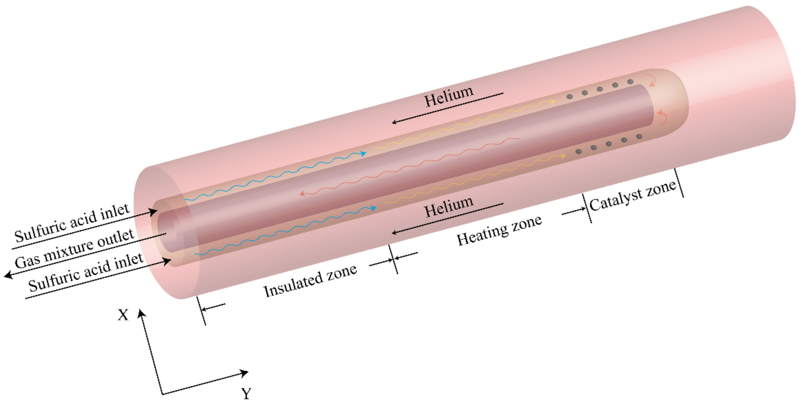
The bayonet heat exchanger is used for sulfuric acid decomposition (Figure 1). This kind of heat exchanger is used for heat exchange of working fluid under high temperature and high pressure. It can not only ensure safety, but also reuse waste heat [29]. It is made of silicon carbide which prevents sulfuric acid corrosion at high temperatures. Liquid sulfuric acid enters from the annulus part of the heat exchanger and passes through the insulated zone and heating zone to gradually increase the temperature. It then completes the chemical reaction in the catalytic zone and flows out of the heat exchanger from the inner tube. During the process, the sulfuric acid in the annulus area conducts countercurrent heat exchange with the helium outside. It also recovers the heat of the working fluid in the inner tube. Sulfuric acid decomposition mainly occurs in the catalytic zone. As such, this study focuses on the flow and heat transfer in this part. The decomposition rates of different structures are also calculated.
The length of the catalytic zone of the bayonet heat exchanger is short. Cognizant to this, increasing the decomposition rate in this limited space was the focus of this study. Lee et al. reported that the decomposition rate was influenced by the space occupied by the catalyst, flow rate, and temperature [30]. Cognizant to this, the heat exchange area of the inner tube and the volume of the annulus catalytic zone were used as indicators. The single inner tube of the original structure is replaced with two inner tubes (Figure 2). The size of structure 1 is based on the design of Corgnale et al. [13]. The total length of the catalytic zone is 0.3 m while the outer and inner diameters of the heat exchanger are 0.1 m and 0.05 m, respectively. Helium gas flows around the heat exchanger. The total heat transfer area of the two inner tubes of structure 2 is similar to that of structure 1. In the same line, the total catalytic volume of structure 3 is similar to that of structure 1. The diameters of each inner tube of structure 2 and structure 3 are 0.025 m and 0.0354 m, respectively. The length of the inner tube of the two structures is 0.3 m, and the distance between the central axis of the two inner tubes is 0.045 m.
2.2. Thermal Hydraulics and Species Transport Model
This study treats the catalyst as a porous medium to simplify the calculations. Zhang et al. revealed that sulfuric acid could be completely decomposed before entering the catalytic zone [31]. As such, the working fluids entering the annular region of the current structure are treated as sulfur trioxide and water. The maximum Reynolds number of the fluid in the structure of this study is 293, which belongs to the range of laminar flow, so the laminar model is used for calculation. Numerical simulation in the decomposition process involves flow, heat transfer and chemical reactions, and related mathematical models used to solve the mass, momentum, and energy equations [32].
The mass balance equation is:
where ρ is the density of the working fluid, U is the velocity vector and Sm is the additional source term for the continuous phase.
The conservation of momentum equation is:
where p is the static pressure, μ is the viscosity, I is the unit tensor, g is the acceleration of gravity and Si is the momentum source term for the catalyst zone. In the porous medium region, the momentum source can be expressed as a function of viscosity and inertia loss terms. In the non-porous medium region, Si was equal to 0. The viscosity and inertial loss coefficient are important parameters that describe a porous media. They are thus directly related to catalyst particle size and porosity [33].
where Dp is the pellet diameter of 5 × 10⁻³ m and ε is the catalyst zone porosity of 0.48. The conservation of momentum equation used to calculate the temperature field is [34]:
where h is the fluid enthalpy and T is the mass-weighted average temperature of the fluid and catalyst particles in the catalytic zone. ST is the energy source term at temperature T and cp is the effective specific heat. Its calculation method is similar to that of temperature. It is the mass-weighted average specific heat of the fluid in the catalytic zone and the catalyst particles. λeff is the effective thermal conductivity. It is related to the fluid thermal conductivity of the catalytic zone (λf), the thermal conductivity of the catalyst particles (λs), and the porosity as depicted in Equation (9).
The sulfur trioxide entering the heat exchanger undergoes decomposition reaction to generate sulfur dioxide and oxygen. The species transportation model can be used to calculate the component distribution of reactants and products using Equations (10)–(13) [21].
where Yi represents the local mass fraction of species i, Ji is the diffusion flux of species i, and Mw,i is the molecular weight of substance i. i,r is the Arrhenius molar ratio of substance i produced or destroyed in reaction r, NR is the quantity of the chemical substance in the system, and mi is the mass source term of each substance. The reaction is assumed to occur in the continuous phase along the wall. Cj,r is the molar concentration of substance j in reaction r, and is the reaction rate index of component j in reaction r. is the rate index of component j of reaction r while is the stoichiometric coefficient of reactant i in reaction r. is the stoichiometric coefficient of product component i in reaction r. Ar is the pre-index factor, βr is the temperature index (dimensionless), Er is the reaction activation energy and R is the ideal gas constant.
The setting of the pre-index factor are determined based on the calculation model results of Sun et al. [19]. The experimental results of sulfuric acid decomposition at high temperature are used to determine the reaction activation energy [35]. The reaction rate constant is thus expressed as (14):
The commercial software ANSYS Fluent is used to solve the equations based on the finite volume method. The second-order upwind method is used to solve the mass, momentum, and energy equations. The steady-state temperature field and velocity distribution are calculated using the classic SIMPLE (Semi-Implicit Method for Pressure-Linked Equations) algorithm with a suitable residual convergence criterion. The convergence residual of the mass and momentum equation is 10−5, and the convergence residual of the energy equation is 10−6. The inlet boundary conditions of various substances are the velocity inlet while the outlet boundary conditions are the pressure outlet.
3. Working Conditions and Simulation Methods
3.1. Properties
The calculation conditions of the bayonet heat exchanger are displayed in Table 1. The physical properties of various substances are those outlined in the user guide [36]. The inlet temperature and pressure of helium and working fluid mixture are determined based on the operating conditions of the very high temperature gas-cooled reactor (VHTR). The vapor mixture density is calculated using the incompressible ideal gas model. The catalyst material is Pt/SiC which has good catalytic performance and thermal conductivity.
3.2. Numerical Methods and Model Verification
The geometric model includes the helium side and the gas mixture side. The tetrahedral grid which is generated by the software ICEM is used to cover the entire fluid area while a slip boundary is employed on the helium side to be close to the real physical situation, the degree of deformation of each grid cell is tested by the Jacobian criterion [37], and it is shown that the global grid quality can reach more than 0.5, which can meet the calculation requirements. The outer surface on the helium side adopts an adiabatic boundary. The boundary layer is divided into five layers of grid, the maximum size is 0.005 m, the height of the first layer is 0.001 m, and the growth rate is 1.1. The boundary layers are added on the inner and outer walls of the sulfuric acid side to improve the calculation accuracy. The specific meshing is shown in Figure 3.
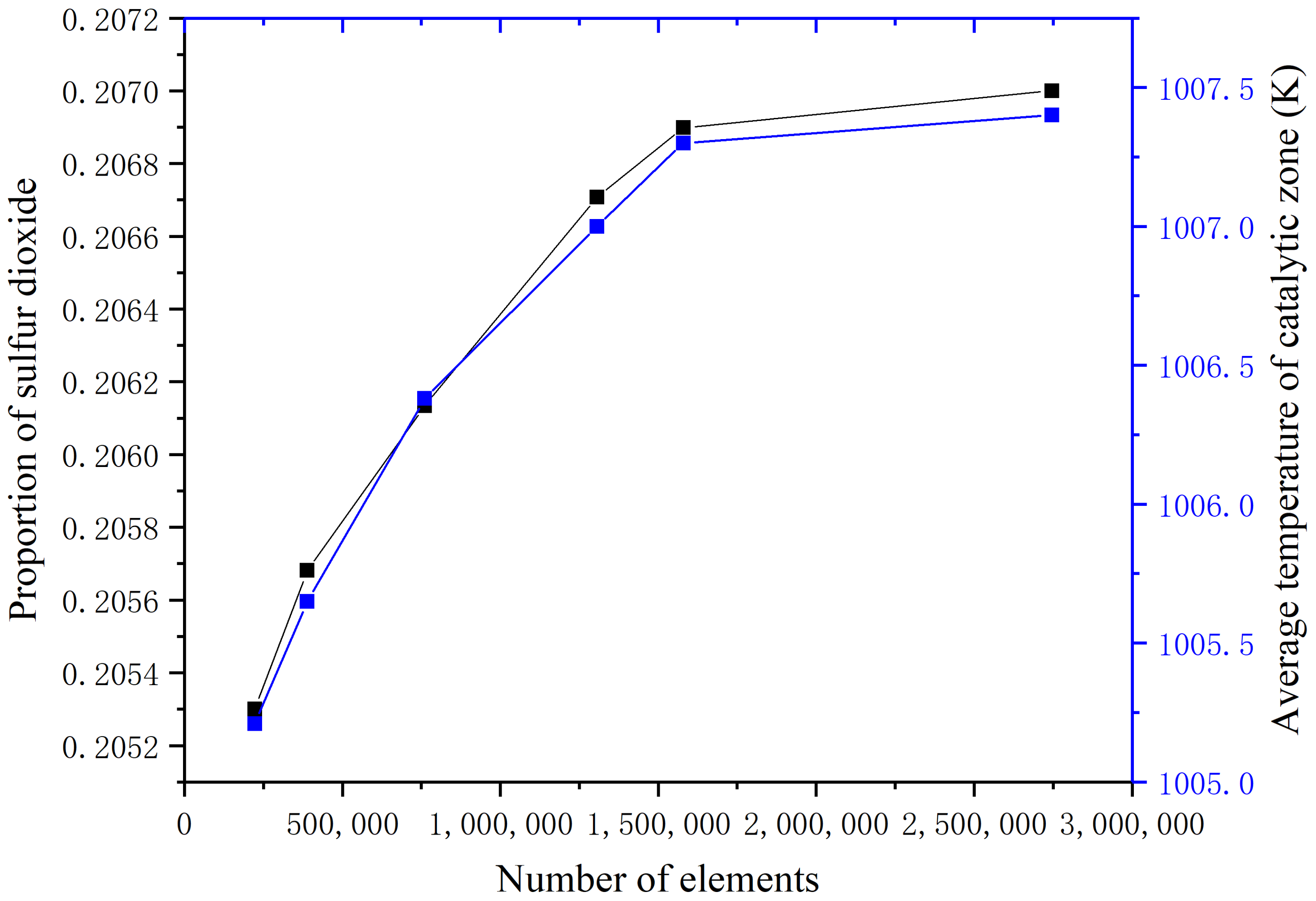
The sulfur dioxide output of the bayonet heat exchanger is an important indicator for evaluating the decomposition rate. Cognizant to this, the grid independence is verified by monitoring the maximum proportion of sulfur dioxide and the average temperature of the porous medium (Figure 4). Approximately 1,570,000 volumes can provide cost-effective results.
The species transport model is adopted in this study. The decomposition of sulfur trioxide is thus calculated in combination with the volume reaction method. The research results of Corgnale et al. [13] are used for comparative verification. The specific simulation conditions are shown in Table 2.
Change in temperature is calculated in the catalytic zone to verify the accuracy and rationality of the model (Figure 5). The gas mixture and helium temperature change trends are basically the same compared to previous results. The fluid temperature of the inner tube is about 925 K while the helium temperature is reduced by about 30 K. The error is thus within 5%. Nonetheless, there is a slight difference between the maximum temperature of the gas mixture and the experimental results. It is attributed to differences in structure length.
Weight hourly space velocity (WHSV) is an important indicator used to measure the decomposition rate [38]. It is defined as the inlet sulfuric acid flow rate per unit of catalyst mass. An experiment on the wide range application of WHSV was implemented by Zhang et al. [27]. Table 3 shows the relevant experimental and simulation results of the method. The error is caused by slight differences in the experimental methods. Simulated actual working conditions and the physical properties of the mixture at high temperature also have an impact. The verification results of the decomposition rate demonstrate that the method can be used for subsequent structural optimization design.
4. Results and Discussion
4.1. Flow and Heat Transfer Analysis
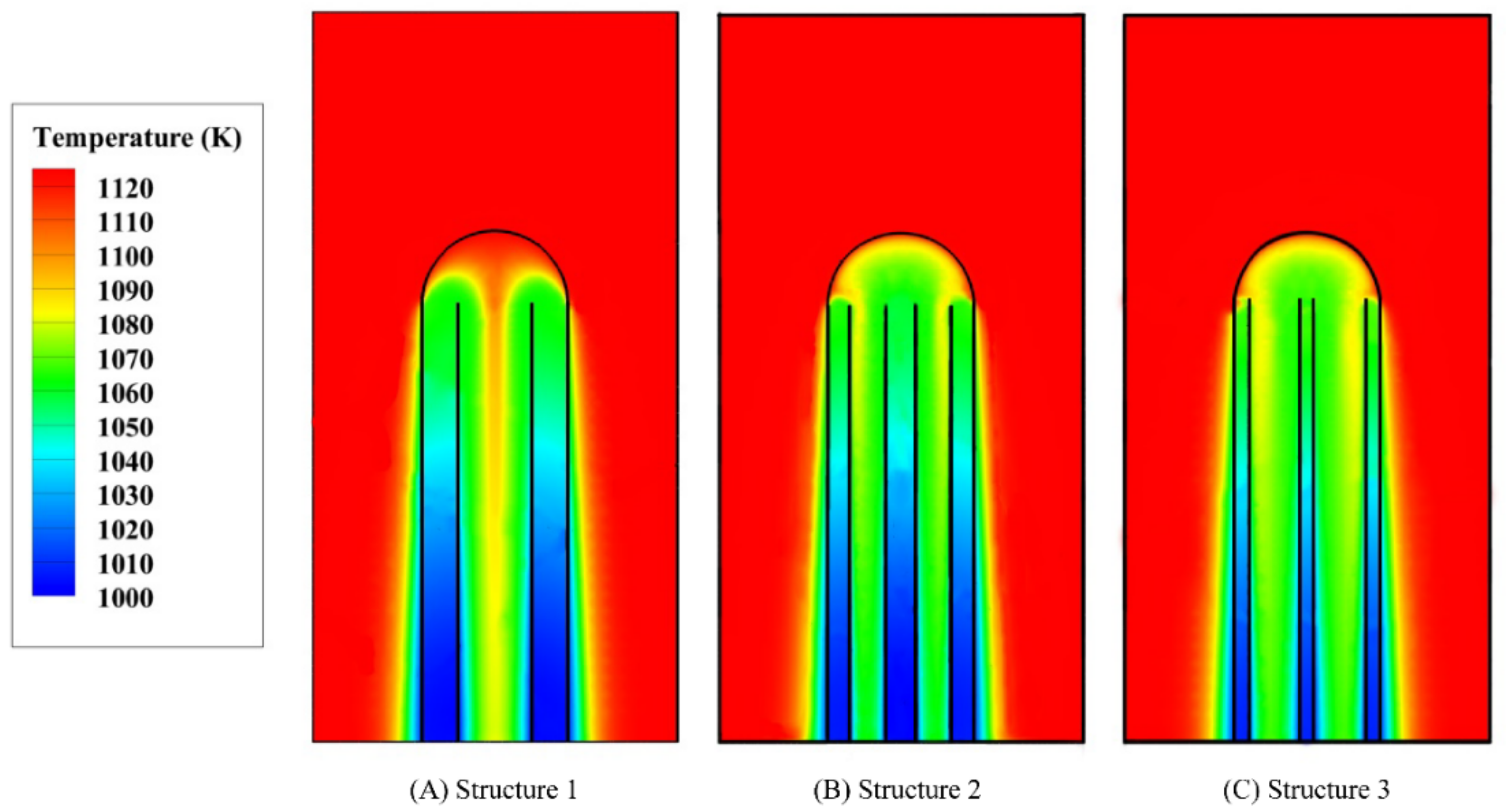
Sulfur trioxide decomposition is an endothermic reaction that mainly occurs in the catalytic zone of the bayonet heat exchanger. The temperature and velocity field distribution of this part have an important influence on the decomposition. Figure 6 shows the temperature distribution of the three structures. The temperature of the fluid just entering the catalytic zone is reduced but the temperature drop of structure 2 is relatively larger. This indicates that the endothermic reaction is stronger. The temperature continues to rise with the heating of the external helium gas. Along the same lines, the mixture turned back from the inner tube can also heat the sulfur trioxide in the annulus area. The average outlet temperature of the mixture of the three structures is about 1040 K. However, the outlet temperature of structure 3 is relatively low which indicates that the heat recovery is sufficient. The temperature gradient of helium gas close to the wall is large. Nonetheless, it gradually decreases along the outer wall of the heat exchanger. The local minimum temperature is about 1020 K. Notably, the average temperature drop of helium gas throughout the process is about 20 K. Nagarajan et al. [39] used a user defined function to obtain the helium distribution near the wall, and the lowest temperature is about 1027 K, which is close to the result of this study.
Figure 7 shows the velocity field distribution of the three structures. Differences in flow velocity inside the inner tube affect the heat transfer as well as the decomposition rate. Although the inlet flow of the three structures is the same, the cross-sectional area of the annulus and the inner tube are different. This leads to differences in velocity distribution. The cross-sectional area of the annulus area of structure 2 is slightly larger than that of the other two structures. The average flow velocity in the annulus area is about 0.13 m/s. Moreover, structures 1 and 3 have equal cross-sectional areas of the annulus area. The average flow velocity is, therefore, about 0.15 m/s which is slightly higher than that of structure 2. Along the same lines, the cross-sectional areas of the inner tube of structures 1 and 3 are large and thus the maximum flow velocity does not exceed 0.8 m/s. However, the flow velocity of the inner tube of structure 2 reaches more than 1.5 m/s, thus significantly promoting heat transfer. Moreover, the thinner inner tube of structure 2 has a thinner boundary layer which further reduces the thermal resistance. As such, structure 2 has a higher advantage in heat exchange performance. Figure 8 shows the heat transfer coefficient changes at different positions of the inner tube. Through the heat flux, the average temperature of the fluid in the inner tube and the temperature of the inner tube wall, the heat transfer coefficient can be calculated by Equation (16). Full flow development causes the heat transfer coefficient of the inner tube to gradually decrease along the flow direction. Nevertheless, the flow velocity of the inner tube of structure 2 is greater which causes it to have a relatively larger heat transfer coefficient. The heat transfer coefficient of structure 2 is the largest followed by that of structure 3 and 1, respectively.
where q represents the heat flux, hwall is the heat transfer coefficient, Tinner is the average temperature of the fluid in the inner tube and Twall is the temperature of the inner tube wall.
4.2. Sulfur Trioxide Decomposition
Figure 9 shows the distribution of reactants and products in a stable state. Sulfur trioxide is gradually decomposed under the action of the catalyst at high temperature thereby generating sulfur dioxide and oxygen in a ratio of 2:1, The decomposition reaction is over when it reaches the bottom of the reactor. Structure 2 has the highest production followed by structures 3 and 1, respectively. This is attributed to the larger catalyst volume of structure 2 compared to that of 1 despite both structures having equal heat exchange areas. This provides favorable conditions for the decomposition of sulfur trioxide. In the same line, structure 3 has the same catalytic volume as that of structure 1 but a relatively high inner tube flow rate and a larger heat transfer coefficient than structure 1. Cognizant to this, the heat exchange performance and the sulfur dioxide generation of structure 3 is more enhanced than that of structure 1.
Figure 10 shows the proportion of sulfur dioxide in the annulus of the three structures. The amount of sulfur dioxide generated in structure 2 remains the highest with a maximum decomposition rate of 79.6%. The amount of sulfur dioxide generated in structure 3 is higher than that generated in structure 1. The maximum decomposition rates of structures 3 and 1 are 75.3% and 73.7%, respectively. This indicates that an increase of the catalytic volume significantly improves the decomposition rate compared to increasing the heat exchange area of the inner tube in the catalytic zone.
Figure 11 shows the reaction heat distribution of the three structures on different height sections. The total length of the catalytic zone is 0.3m and thus three different sections are selected to reflect the changes in the decomposition degree. The strong endotherm of the reactants near the inlet indicates that the number of reactants participating in the reaction is large. The reaction gradually weakens and the endothermic heat decreases with continuous reaction progress. The reaction ends and the endothermic gradually drops to zero when the fluid gets to the bottom of the heat exchanger. The cross-sectional area of the inner tube of structure 2 is smaller than that of the other two structures. As such, there is still some reaction space between the two inner tubes. Its larger catalytic volume also enables more reactants to participate in the decomposition process. The cross-sectional area of the inner tube of structure 3 is slightly larger than that of structure 2. This results in insufficient use of the space between the two inner tubes causing the number of reactants participating in the reaction to be less than those of structure 2. However, its larger heat exchange area improves the heat exchange effect and enhance the reaction intensity thus causing it to have a better decomposition effect than structure 1.
4.3. Effect of Flow Rate on Decomposition
Table 4 and Figure 12 shows changes in the decomposition rates of the three structures with the inlet flow rate. As the flow rate increases, the residence time of the reactants in the catalytic zone decreases. This makes the reaction insufficient, thereby resulting in a decrease in the decomposition rate. Nonetheless, when the flow rate increases to a certain extent, there is a moderate change in the decomposition rate. The decomposition rates of the improved structures 2 and 3 are better than that of structure 1. This suggests that the current design significantly improves the decomposition rate by increasing the catalytic volume of annulus and heat exchange area of inner tube in a range of large variable flow rates.
Figure 13 shows the optimization effect comparisons of structural designs under different flow rates. The increase of the flow rate can strengthen the inner tube recovery effect of the inner tube, but also shorten the residence time of the reactants in the catalytic zone. Therefore, there is a suitable inlet flow rate to maximize the overall sulfuric acid decomposition rate. Improvement of structure 2 significantly increases the decomposition rate by up to 6.1%. Similarly, improvement of structure 3 also increases the decomposition rate by up to 1.7%. Notably, when the flow rate is lower than 0.2 m/s, the heat recovery effect of the inner tube is more affected, which can further increase the decomposition rate. The increase reaches its highest level when the flow rate is about 0.2 m/s. The optimization effect of the two structures is gradually weakened as the flow rate continues to increase, the residence time of the working fluid in the catalytic zone has a greater impact in this speed range. This strongly suggests that the current structure design has a better effect on low flow rates.
5. Conclusions
This study simulates the decomposition reaction process in the catalytic zone of the decomposer unit and two facets of the structure of the bayonet heat exchanger are improved: the heat exchange area of the inner tube and the catalytic volume of the annulus area. The results further reveal that:
- (1)
- The structure of the double inner tube can increase the decomposition rate of sulfuric acid. The main mechanism is to strengthen heat recovery and increase the layout space of the catalyst.
- (2)
- Structure 2 studied in this paper has better performance than structure 1. The reason is that the higher velocity of the fluid in the tube enhances the heat transfer, and the larger catalytic volume increases the sulfuric acid decomposition rate.
- (3)
- The decomposition rate is negatively correlated with the flow rate. Nonetheless, the decomposition rate of sulfuric acid can be increased by up to 6.1%. The decomposition rate can be maintained at a relatively high level when the inlet velocity of the current structural design is about 0.2 m/s.
Author Contributions
Conceptualization, Q.G.; methodology, Q.G. and W.P.; software, G.Z.; validation, S.C., W.P. and P.Z.; formal analysis, W.P.; investigation, Q.G.; resources, P.Z.; data curation, S.C.; writing—original draft preparation, Q.G.; writing—review and editing, W.P.; visualization, W.P.; supervision, W.P.; project administration, W.P.; funding acquisition, P.Z. All authors have read and agreed to the published version of the manuscript.
Funding
This project was supported by the National Key R&D Program of China (Grant No. 2020YFB1901600) and the National S&T Major Project (Grant No. ZX069).
Institutional Review Board Statement
Not applicable.
Informed Consent Statement
Informed consent was obtained from all subjects involved in the study.
Data Availability Statement
The authors declare that they have no known competing financial interests or personal relationships that could have appeared to influence the work reported in this paper.
Conflicts of Interest
The authors declare no conflict of interest.
Nomenclature
| ac | porous media viscous resistance coefficients (m2) |
| Ar | pre-exponential factor (s−1) |
| cp | effective specific heat (J/(kg·K)) |
| C2 | porous media inertial resistance coefficient (1/m) |
| Cj,r | molar concentration of reactant j in reaction r (kmol/m3) |
| Dp | catalyzer pellet diameter (m) |
| Er | activation energy for reaction r (J/mol) |
| g | acceleration of gravity (m/s2) |
| h | fluid enthalpy (J/kg) |
| hwall | heat transfer coefficient (W/(m2·K)) |
| k | reaction rate constant (s−1) |
| m | net mass source (kg/m3·s−1) |
| M | molecular weight (kg/kmol) |
| p | pressure (Pa) |
| q | heat flux (W/m2) |
| Ri,r | molar transfer rates in reaction r (kmol/m3·s−1) |
| R | gas constant (J·mol−1·K−1) |
| T | fluid temperature (K) |
| U | velocity vector (m/s) |
| Yi | local mass fraction of species i |
| Greek letters | |
| β | temperature index |
| ρ | density (kg/m3) |
| ε | porosity |
| μ | viscosity (Pa·s) |
| λeff | effective thermal conductivity (W/(m·K)) |
| Subscripts | |
| i,j | species |
| r | reaction |
| f | fluid |
| s | solid |
References
- Zhou, J.; Guo, Y.; Huang, Z.; Wang, C. A review and prospects of gas mixture containing hydrogen as vehicle fuel in China. Int. J. Hydrog. Energy 2019, 44, 29776–29784. [Google Scholar] [CrossRef]
- Mengjiao, W.; Guizhou, W.; Zhenxin, S.; Yukui, Z.; Dong, X. Review of renewable energy-based hydrogen production pro-cesses for sustainable energy innovation. Glob. Energy Interconnect. 2019, 2, 436–443. [Google Scholar]
- Ostadi, M.; Paso, K.G.; Rodriguez-Fabia, S.; Oi, L.E.; Manenti, F.; Hillestad, M. Process integration of green hydrogen: Decarbonization of chemical industries. Energies 2020, 13, 4859. [Google Scholar] [CrossRef]
- Kapłan, R.; Kopacz, M. Economic conditions for developing hydrogen production based on coal gasification with carbon capture and storage in Poland. Energies 2020, 13, 5074. [Google Scholar] [CrossRef]
- Li, P.; Chen, L.; Xia, S.; Zhang, L.; Kong, R.; Ge, Y.; Feng, H. Entropy generation rate minimization for steam methane reforming reactor heated by molten salt. Energy Rep. 2020, 6, 685–697. [Google Scholar] [CrossRef]
- Braga, J.K.; Motteran, F.; Sakamoto, I.K.; Varesche, M.B.A. Bacterial and archaeal community structure involved in biofuels production using hydrothermal- and enzymatic-pretreated sugarcane bagasse for an improvement in hydrogen and methane production. Sustain. Energy Fuels 2018, 2, 2644–2660. [Google Scholar] [CrossRef]
- Kumar, S.S.; Himabindu, V. Hydrogen production by PEM water electrolysis—A review. Mater. Sci. Energy Technol. 2019, 2, 442–454. [Google Scholar]
- Duan, W.; Yu, Q.; Wu, T.; Yang, F.; Qin, Q. Experimental study on steam gasification of coal using molten blast furnace slag as heat carrier for producing hydrogen-enriched syngas. Energy Convers. Manag. 2016, 117, 513–519. [Google Scholar] [CrossRef] [Green Version]
- Qiu, J.; Zhu, L.; Li, L.; He, Y.; Zhou, M. Solar-driven novel methane reforming with carbon looping for hydrogen production. Int. J. Hydrog. Energy 2019, 44, 24441–24449. [Google Scholar] [CrossRef]
- Sun, Q.; Hai, X.; Wang, K.; Peng, W. Study of the deposition of graphite dust in the inlet passageway of intermediate heat exchanger in VHTR. Exp. Comput. Multiph. Flow 2019, 1, 29–37. [Google Scholar] [CrossRef] [Green Version]
- Zhang, P.; Wang, L.J.; Chen, S.Z.; Xu, J.M. Progress of nuclear hydrogen production through the iodine-sulfur process in China. Renew. Sustain. Energy Rev. 2018, 81, 1802–1812. [Google Scholar]
- Hong, S.-D.; Kim, C.-S.; Kim, Y.-W.; Seo, D.-U.; Park, G.-C. Design and analysis of a high pressure and high temperature sulfuric acid experimental system. Nucl. Eng. Des. 2012, 251, 157–163. [Google Scholar] [CrossRef]
- Corgnale, C.; Shimpalee, S.; Gorensek, M.B.; Satjaritanun, P.; Weidner, J.W.; Summers, W.A. Numerical modeling of a bayonet heat exchanger-based reactor for sulfuric acid decomposition in thermochemical hydrogen production processes. Int. J. Hydrog. Energy 2017, 42, 20463–20472. [Google Scholar] [CrossRef]
- Corgnale, C.; Ma, Z.; Shimpalee, S. Modeling of a direct solar receiver reactor for decomposition of sulfuric acid in thermo-chemical hydrogen production cycles. Int. J. Hydrog. Energy 2019, 44, 27237–27247. [Google Scholar] [CrossRef]
- Choi, J.-S.; Choi, J.-H. Experiment and numerical analysis for sulfuric acid decomposition reaction for applying hydrogen by nuclear. Int. J. Hydrog. Energy 2015, 40, 7932–7942. [Google Scholar] [CrossRef]
- Shin, Y.; Lee, T.; Lee, K.; Kim, M. Modeling and simulation of HI and H2SO4 thermal decomposers for a 50 NL/h sulfur-iodine hydrogen production test facility. Appl. Energy 2016, 173, 460–469. [Google Scholar] [CrossRef]
- Park, J.; Cho, J.H.; Jung, H.; Jung, K.-D.; Kumar, S.; Moon, I. Simulation and experimental study on the sulfuric acid de-composition process of SI cycle for hydrogen production. Int. J. Hydrog. Energy 2013, 38, 5507–5516. [Google Scholar] [CrossRef]
- Sun, Q.; Zhao, G.; Peng, W.; Wang, J.; Jiang, Y.; Yu, S. Numerical predictions of the drag coefficients of irregular particles in an HTGR. Ann. Nucl. Energy 2018, 115, 195–208. [Google Scholar] [CrossRef]
- Sun, Q.; Gao, Q.; Zhang, P.; Peng, W.; Chen, S. Modeling sulfuric acid decomposition in a bayonet heat exchanger in the iodine-sulfur cycle for hydrogen production. Appl. Energy 2020, 277, 115611. [Google Scholar] [CrossRef]
- Sun, Q.; Gao, Q.; Zhang, P.; Peng, W.; Chen, S.; Zhao, G.; Wang, J. Numerical study of heat transfer and sulfuric acid decomposition in the process of hydrogen production. Int. J. Energy Res. 2019, 43, 5969–5982. [Google Scholar] [CrossRef]
- Gao, Q.; Sun, Q.; Zhang, P.; Peng, W.; Chen, S. Sulfuric acid decomposition in the iodine–sulfur cycle using heat from a very high temperature gas-cooled reactor. Int. J. Hydrog. Energy 2020. [Google Scholar] [CrossRef]
- Pathak, S.; Goswami, A.; Upadhyayula, S. Kinetic modeling and simulation of catalyst pellet in the high temperature sulfuric acid decomposition section of Iodine-Sulfur process. Int. J. Hydrog. Energy 2019, 44, 30850–30864. [Google Scholar] [CrossRef]
- Nagarajan, V.; Chen, Y.; Wang, Q.; Ma, T. CFD modeling and simulation of sulfur trioxide decomposition in ceramic plate-fin high temperature heat exchanger and decomposer. Int. J. Heat Mass Transf. 2015, 80, 329–343. [Google Scholar] [CrossRef]
- Khan, H.A.; Kim, S.; Jung, K.D. Origin of high stability of Pt/anatase-TiO2 catalyst in sulfuric acid decomposition for SI cycle to produce hydrogen. Catal. Today 2020, 352, 316–322. [Google Scholar] [CrossRef]
- Nadar, A.; Banerjee, A.M.; Pai, M.R.; Meena, S.S.; Patra, A.K.; Sastry, P.U.; Singh, R.; Singh, M.K.; Tripathi, A.K. Immobilization of crystalline Fe2O3 nanoparticles over SiO2 for creating an active and stable catalyst: A demand for high temperature sulfuric acid decomposition. Appl. Catal. B Environ. 2021, 283, 119610. [Google Scholar] [CrossRef]
- Giaconia, A.; Sau, S.; Felici, C.; Tarquini, P.; Karagiannakis, G.; Pagkoura, C.; Agrafiotis, C.; Konstandopoulos, A.G.; Thomey, D.; De Oliveira, L.; et al. Hydrogen production via sulfur-based thermochemical cycles: Part 2: Performance evaluation of Fe2O3-based catalysts for the sulfuric acid decomposition step. Int. J. Hydrog. Energy 2011, 36, 6496–6509. [Google Scholar] [CrossRef]
- Zhang, P.; Su, T.; Chen, Q.; Wang, L.; Chen, S.; Xu, J. Catalytic decomposition of sulfuric acid on composite oxides and Pt/SiC. Int. J. Hydrog. Energy 2012, 37, 760–764. [Google Scholar] [CrossRef]
- Stander, B.; Everson, R.; Neomagus, H.; Van Der Merwe, A.; Tietz, M. Sulphur trioxide decomposition with supported platinum/palladium on rutile catalyst: 2. Performance of a laboratory fixed bed reactor. Int. J. Hydrog. Energy 2015, 40, 2493–2499. [Google Scholar] [CrossRef]
- Mathur, A.; Saxena, S.; Qureshi, Z. Heat transfer to a bayonet heat exchanger immersed in a gas-fluidized bed. Int. Commun. Heat Mass Transf. 1983, 10, 241–252. [Google Scholar] [CrossRef]
- Lee, Y.H.; Lee, J.I.; No, H.C. A point model for the design of a sulfur trioxide decomposer for the SI cycle and comparison with a CFD model. Int. J. Hydrog. Energy 2010, 35, 5210–5219. [Google Scholar] [CrossRef]
- Zhang, P.; Zhou, C.; Guo, H.; Chen, S.; Wang, L.; Xu, J. Design of integrated laboratory-scale iodine sulfur hydrogen production cycle at INET. Int. J. Energy Res. 2016, 40, 1509–1517. [Google Scholar] [CrossRef]
- Batchelor, C.K.; Batchelor, G. An Introduction to Fluid Dynamics; Cambridge University Press: Cambridge, UK, 2000. [Google Scholar]
- Nagarajan, V.; Ponyavin, V.; Chen, Y.; Vernon, M.E.; Pickard, P.; Hechanova, A.E. CFD modeling and experimental validation of sulfur trioxide decomposition in bayonet type heat exchanger and chemical decomposer for different packed bed designs. Int. J. Hydrog. Energy 2009, 34, 2543–2557. [Google Scholar] [CrossRef]
- Hayes, A.M.; Khan, J.A.; Shaaban, A.H.; Spearing, I.G. The thermal modeling of a matrix heat exchanger using a porous medium and the thermal non-equilibrium model. Int. J. Therm. Sci. 2008, 47, 1306–1315. [Google Scholar] [CrossRef]
- Ginosar, D.; Petkovic, L.M.; Burch, K.C. Activity and Stability of Catalysts for the High Temperature Decomposition of Sulfuric Acid; Idaho National Laboratory: Idaho Falls, ID, USA, 2005. [Google Scholar]
- ANSYS Incorporated. ANSYS Fluent User Guide; ANSYS, Inc.: Canonsburg, PA, USA, 2017. [Google Scholar]
- ANSYS Incorporated. CFD, ICEM CFD Theory Guide; ANSYS, Inc.: Canonsburg, PA, USA, 2015. [Google Scholar]
- Iulianelli, A.; Liguori, S.; Longo, T.; Tosti, S.; Pinacci, P.; Basile, A.A. An experimental study on bio-ethanol steam reforming in a catalytic membrane reactor. Part II: Reaction pressure, sweep factor and WHSV effects. Int. J. Hydrog. Energy 2010, 35, 3159–3164. [Google Scholar] [CrossRef]
- Nagarajan, V.; Ponyauin, V.; Chen, Y.; Vernon, M.E.; Pickard, P.; Hechanova, A.E. Numerical study of sulfur trioxide decomposition in bayonet type heat exchanger and chemical decomposer with porous media zone and different packed bed designs. Int. J. Hydrog. Energy 2008, 33, 6445–6455. [Google Scholar] [CrossRef]
Figure 1.
Geometric model of bayonet heat exchanger.

Figure 2.
Structural optimization of the catalytic zone of bayonet heat exchanger. (A) Structure 1 (inner tube diameter: 0.05 m, heat exchange area: 0.047 m2, catalyst volume: 0.00177 m3). (B) Structure 2 (inner tube diameter: 0.025 m, heat exchange area: 0.047 m2, catalyst volume: 0.00206 m3). (C) Structure 3 (inner tube diameter: 0.025 m, heat exchange area: 0.067 m2, catalyst volume: 0.00177 m3).

Figure 3.
Meshing of the bayonet heat exchanger.

Figure 4.
Grid independence verification.

Figure 5.
Numerical method verification of temperature field.

Figure 6.
Temperature distribution in the bayonet heat exchanger for an inlet flow rate of 0.00035 kg/s. (A) Structure 1, (B) Structure 2, (C) Structure 3.
Figure 6.
Temperature distribution in the bayonet heat exchanger for an inlet flow rate of 0.00035 kg/s. (A) Structure 1, (B) Structure 2, (C) Structure 3.

Figure 7.
Velocity distribution in the bayonet heat exchanger for an inlet flow rate of 0.00035 kg/s. (A) Structure 1, (B) Structure 2, (C) Structure 3.
Figure 7.
Velocity distribution in the bayonet heat exchanger for an inlet flow rate of 0.00035 kg/s. (A) Structure 1, (B) Structure 2, (C) Structure 3.

Figure 8.
The heat transfer coefficients of inner tubes with different structures in the bayonet heat exchanger.
Figure 8.
The heat transfer coefficients of inner tubes with different structures in the bayonet heat exchanger.

Figure 9.
Spatial distributions of the species molar fractions in the bayonet heat exchanger for an inlet flow rate of 0.00035 kg/s. (A) Structure 1, (B) Structure 2, (C) Structure 3.
Figure 9.
Spatial distributions of the species molar fractions in the bayonet heat exchanger for an inlet flow rate of 0.00035 kg/s. (A) Structure 1, (B) Structure 2, (C) Structure 3.

Figure 10.
Comparison of the predicted sulfur dioxide molar fraction distribution in the annulus.

Figure 11.
Reaction heat production distribution in the bayonet heat exchanger for an inlet flow rate of 0.00035 kg/s. (A) Structure 1, (B) Structure 2, (C) Structure 3.
Figure 11.
Reaction heat production distribution in the bayonet heat exchanger for an inlet flow rate of 0.00035 kg/s. (A) Structure 1, (B) Structure 2, (C) Structure 3.

Figure 12.
Decomposition rates for various velocities of flow.

Figure 13.
Comparison of improvements in the decomposition rates at varying flow velocities.


Table 1.
Calculation conditions.
| Side | Inlet Flow Rate (kg/s) | Mole Fraction | Pressure (MPa) | Temperature (K) |
|---|---|---|---|---|
| SO3 | 0.00035–0.00128 | 0.5 | 0.1 | 1010 |
| H2O | 0.00035–0.00128 | 0.5 | 0.1 | 1010 |
| He | 0.0083 | 1 | 4.0 | 1123 |
Table 2.
Operating conditions for model verification.
| Reactive Sulfur Mixture Region | Helium Region | |
|---|---|---|
| Inlet temperature (K) | 860 | 1148 |
| Inlet pressure (bar) | 14 | 40 |
| Flow rate (kg/h) | 10.8 | 8.64 |
| SO3 mass fraction | 0.69 | - |
| H2O mass fraction | 0.31 | - |
| He mass fraction | - | 1 |
Table 3.
Numerical method verification of the decomposition rate.
| Condition | WHSV (h−1) | Decomposition Fraction of SO3 by Authors (%) | Decomposition Fraction of SO3 by Present Method (%) |
|---|---|---|---|
| 1 | 10 | 85.0 | 88.0 |
| 2 | 20 | 80.0 | 77.9 |
| 3 | 30 | 65.0 | 62.0 |
| 4 | 40 | 57.0 | 50.5 |
Table 4.
Numerical calculation results of decomposition rates at different velocities.
| Velocity (m/s) | Decomposition Rate of Structure 1 (%) | Decomposition Rate of Structure 2 (%) | Decomposition Rate of Structure 3 (%) |
|---|---|---|---|
| 0.15 | 73.7 | 79.6 | 75.3 |
| 0.2 | 62.0 | 68.1 | 63.7 |
| 0.25 | 53.0 | 58.8 | 54.6 |
| 0.3 | 46.2 | 51.6 | 47.7 |
| 0.35 | 40.8 | 45.7 | 42.2 |
| 0.4 | 36.5 | 41.1 | 37.8 |
| 0.45 | 33.0 | 37.3 | 34.2 |
| 0.5 | 30.2 | 34.1 | 31.2 |
Publisher’s Note: MDPI stays neutral with regard to jurisdictional claims in published maps and institutional affiliations. |
© 2021 by the authors. Licensee MDPI, Basel, Switzerland. This article is an open access article distributed under the terms and conditions of the Creative Commons Attribution (CC BY) license (http://creativecommons.org/licenses/by/4.0/).
Share and Cite
MDPI and ACS Style
Gao, Q.; Zhang, P.; Peng, W.; Chen, S.; Zhao, G. Structural Design Simulation of Bayonet Heat Exchanger for Sulfuric Acid Decomposition. Energies 2021, 14, 422. https://0-doi-org.brum.beds.ac.uk/10.3390/en14020422
AMA Style
Gao Q, Zhang P, Peng W, Chen S, Zhao G. Structural Design Simulation of Bayonet Heat Exchanger for Sulfuric Acid Decomposition. Energies. 2021; 14(2):422. https://0-doi-org.brum.beds.ac.uk/10.3390/en14020422
Chicago/Turabian StyleGao, Qunxiang, Ping Zhang, Wei Peng, Songzhe Chen, and Gang Zhao. 2021. "Structural Design Simulation of Bayonet Heat Exchanger for Sulfuric Acid Decomposition" Energies 14, no. 2: 422. https://0-doi-org.brum.beds.ac.uk/10.3390/en14020422
Note that from the first issue of 2016, this journal uses article numbers instead of page numbers. See further details here.