
The Effects of Using Steam to Preheat the Beds of an Adsorption Chiller with Desalination Function


Abstract
:1. Introduction
2. Methodology
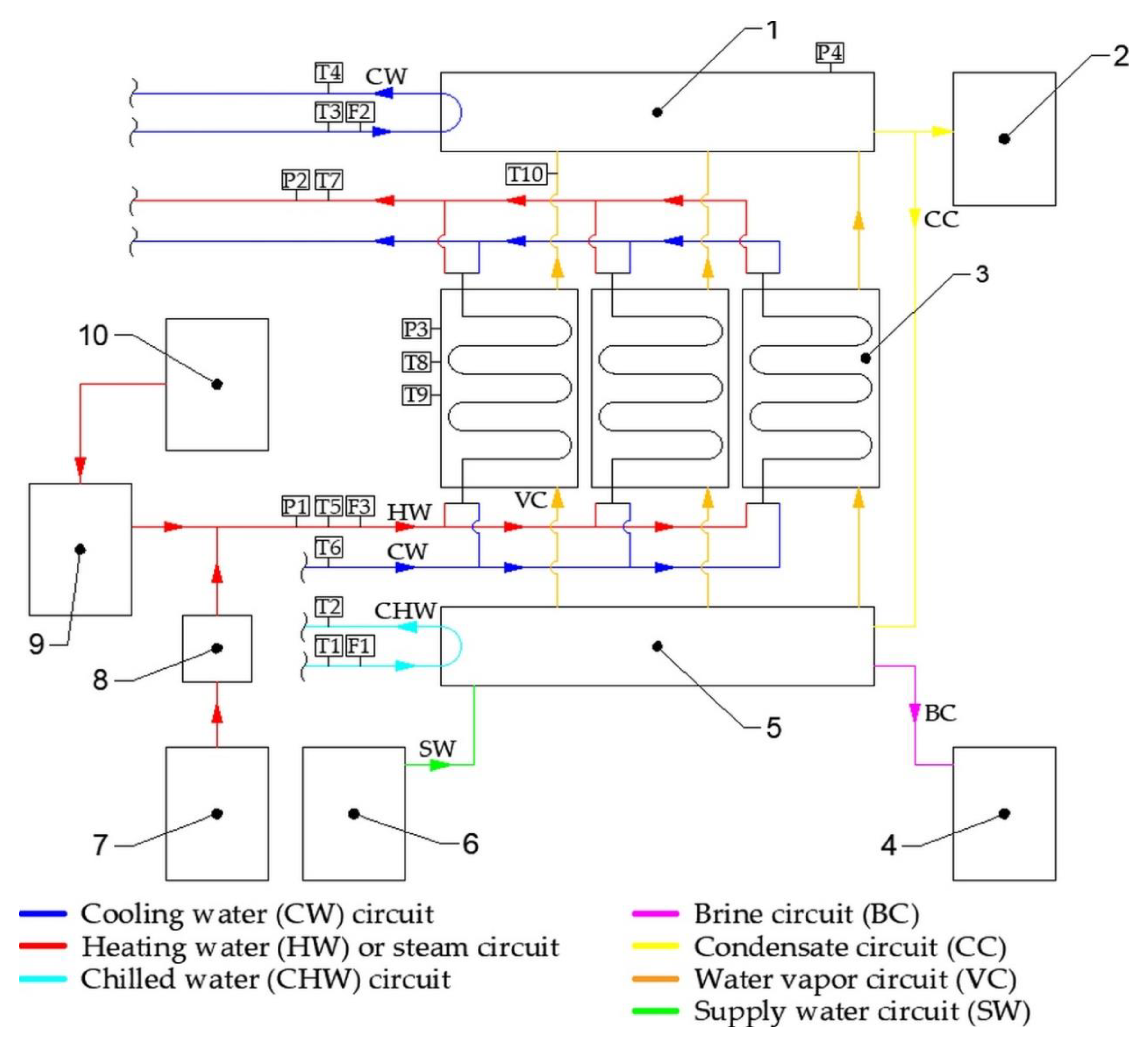
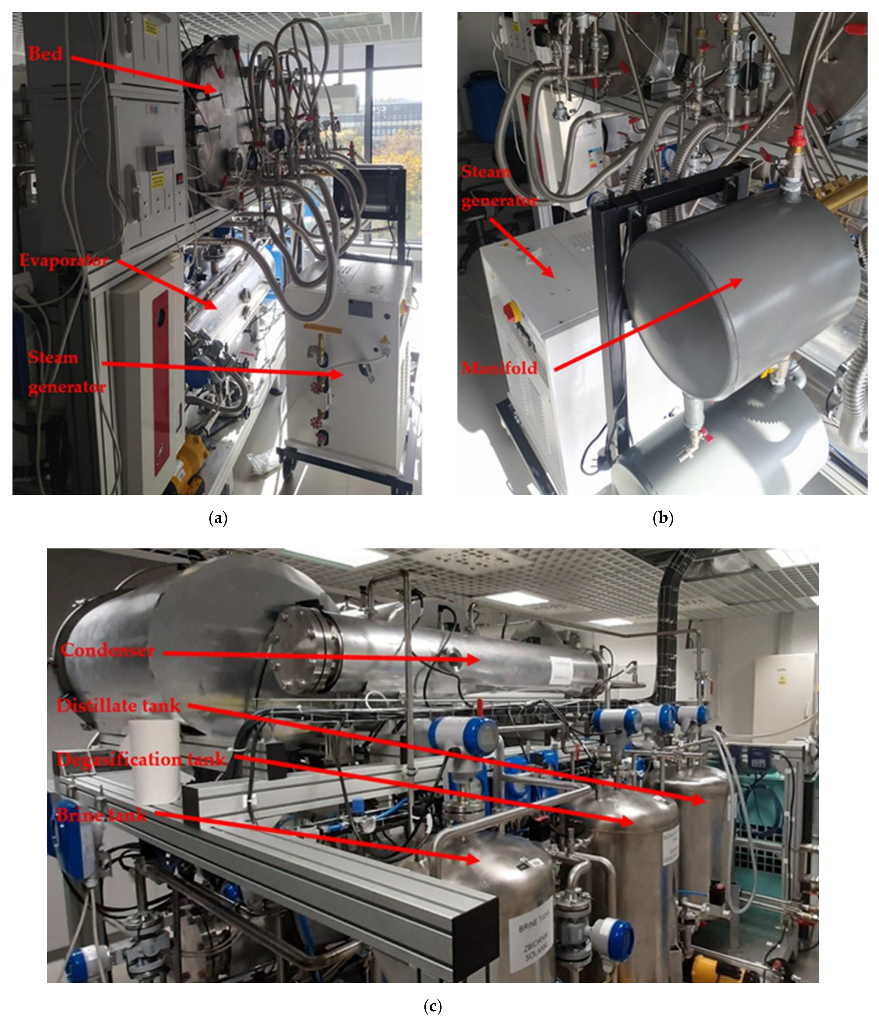
2.1. Test Stand
- With the use of hot water: the water is heated in the electric heater (10) and directed to the hot water tank (9) and, then, to the bed (3), while the steam generator (7) is not used and is cut off from the system by using special valves (not shown in Figure 1).
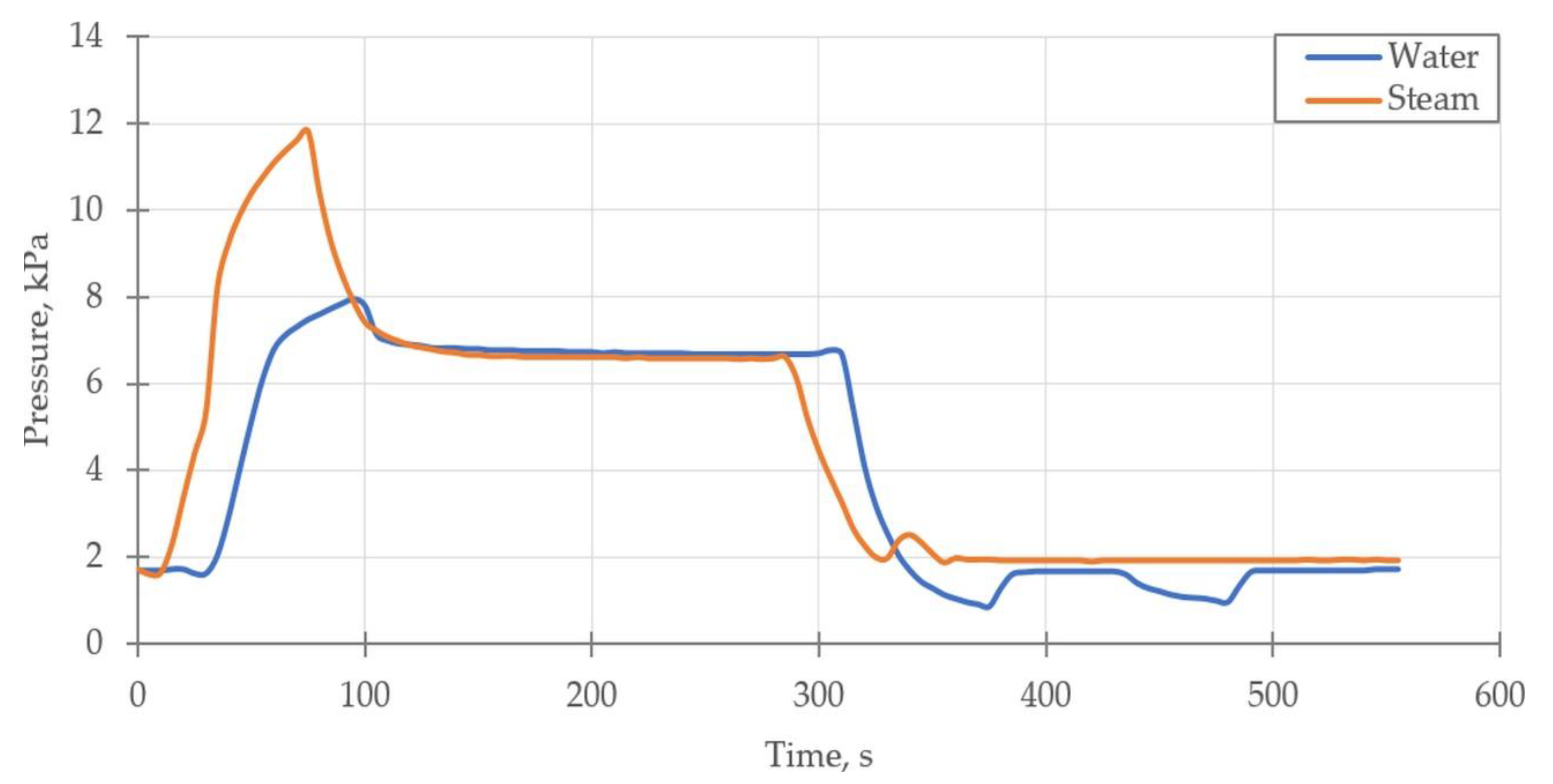
- With the use of steam: steam is generated in the steam generator (7) and directed to the distribution manifold (8) and, then, to the bed (3). Steam flows through the bed for about 50 s (until its inlet and outlet temperatures are equal). Then, the supply of steam to the bed is cut off, and the supply of hot water, used for the desorption process, is opened. After leaving the bed, the steam is returned to the hot water tank.
2.2. Measuring Devices and Uncertainty Analysis
- The inlet and outlet temperatures of heating water or steam (depending on the operation variant of the chiller);
- The temperature inside the heat exchanger;
- The temperature of the free space in the bed;
- The temperature of the water vapor (sorbate) at the outlet of the bed;
- The pressure in the bed;
- The pressure in the condenser;
- The flow rates of heating water, cooling water, chilled water and steam.
2.3. Experimental Procedure
3. Results and Discussion
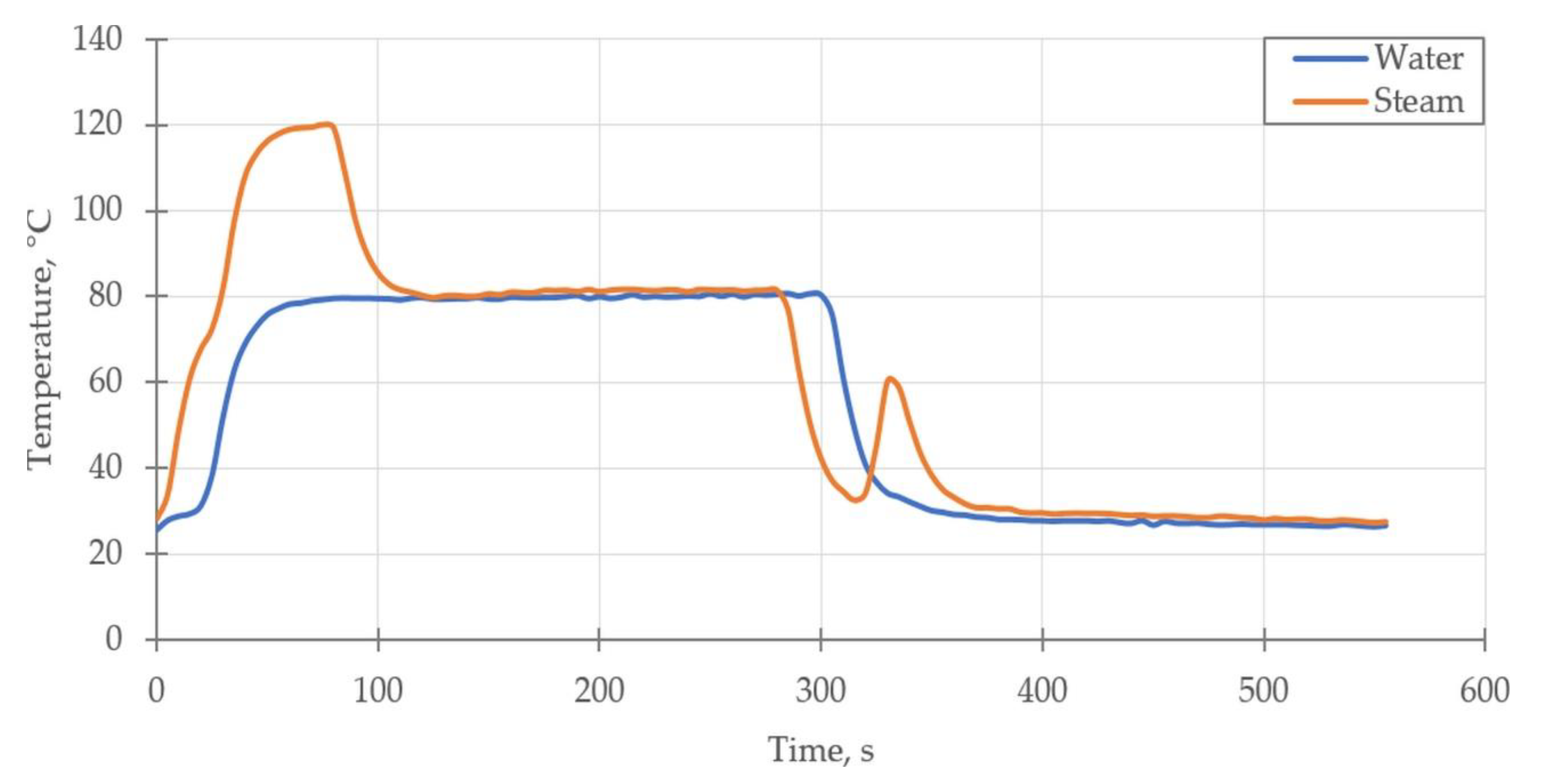
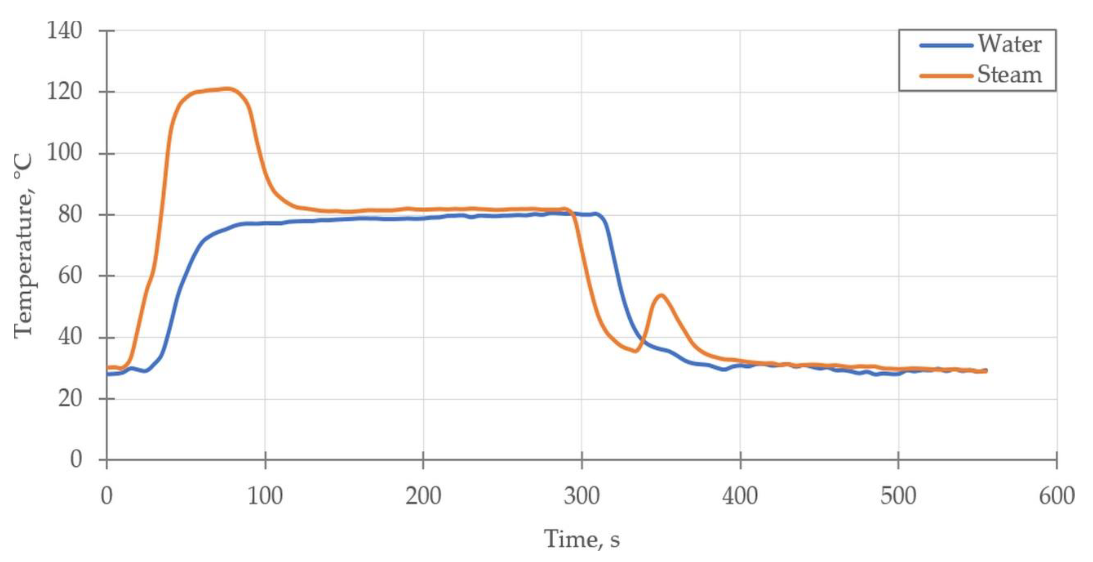
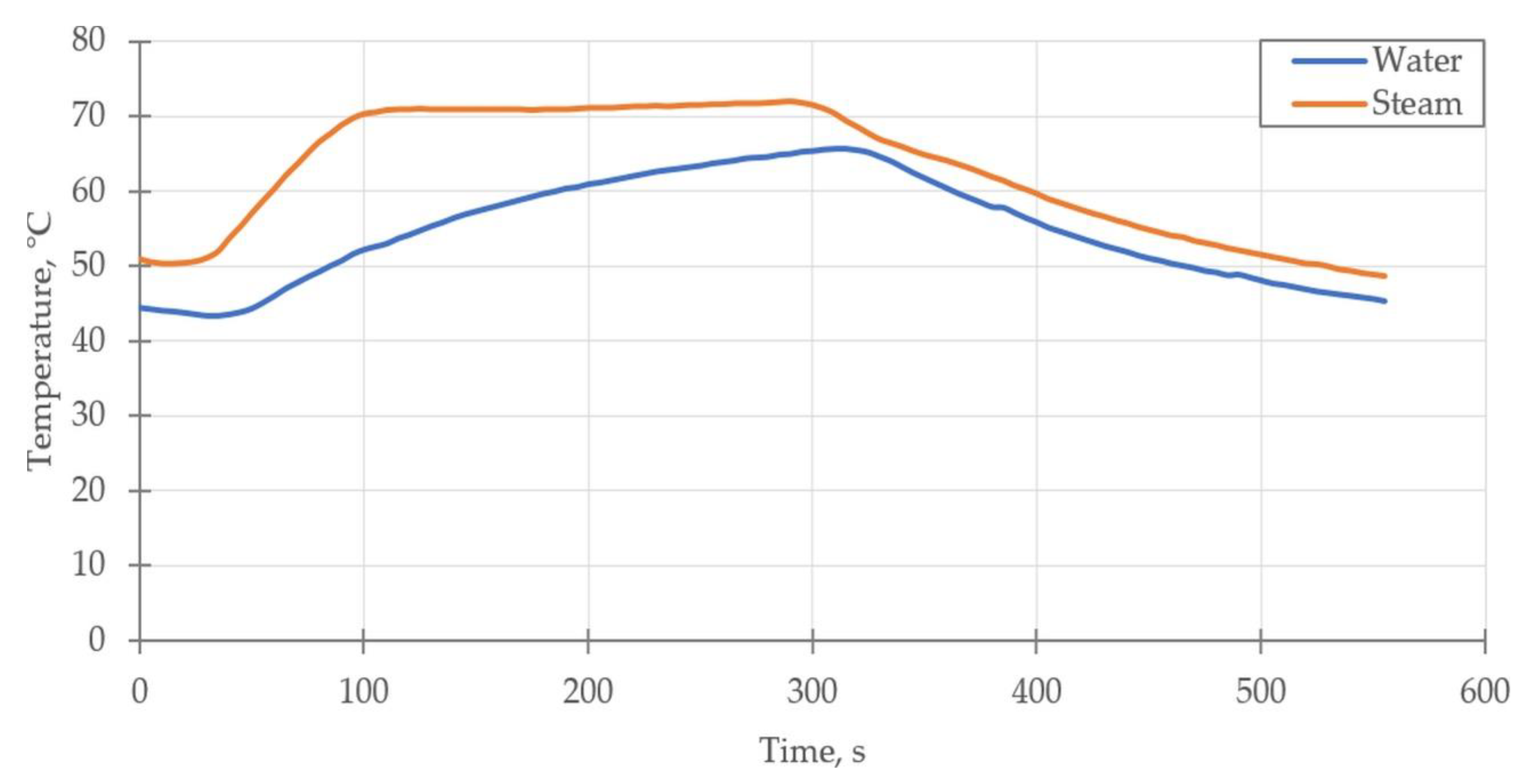
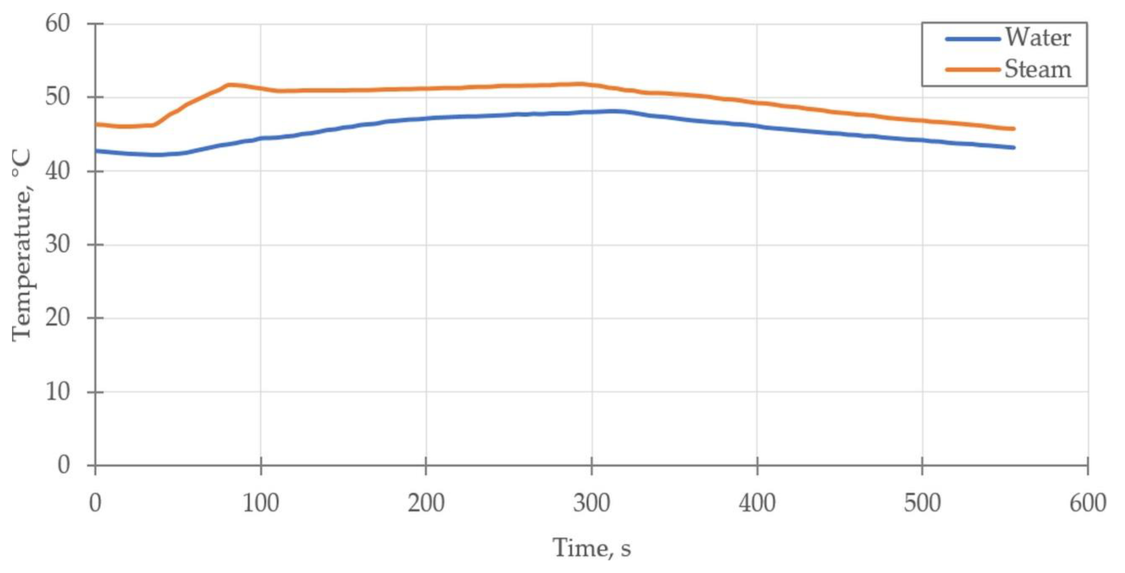
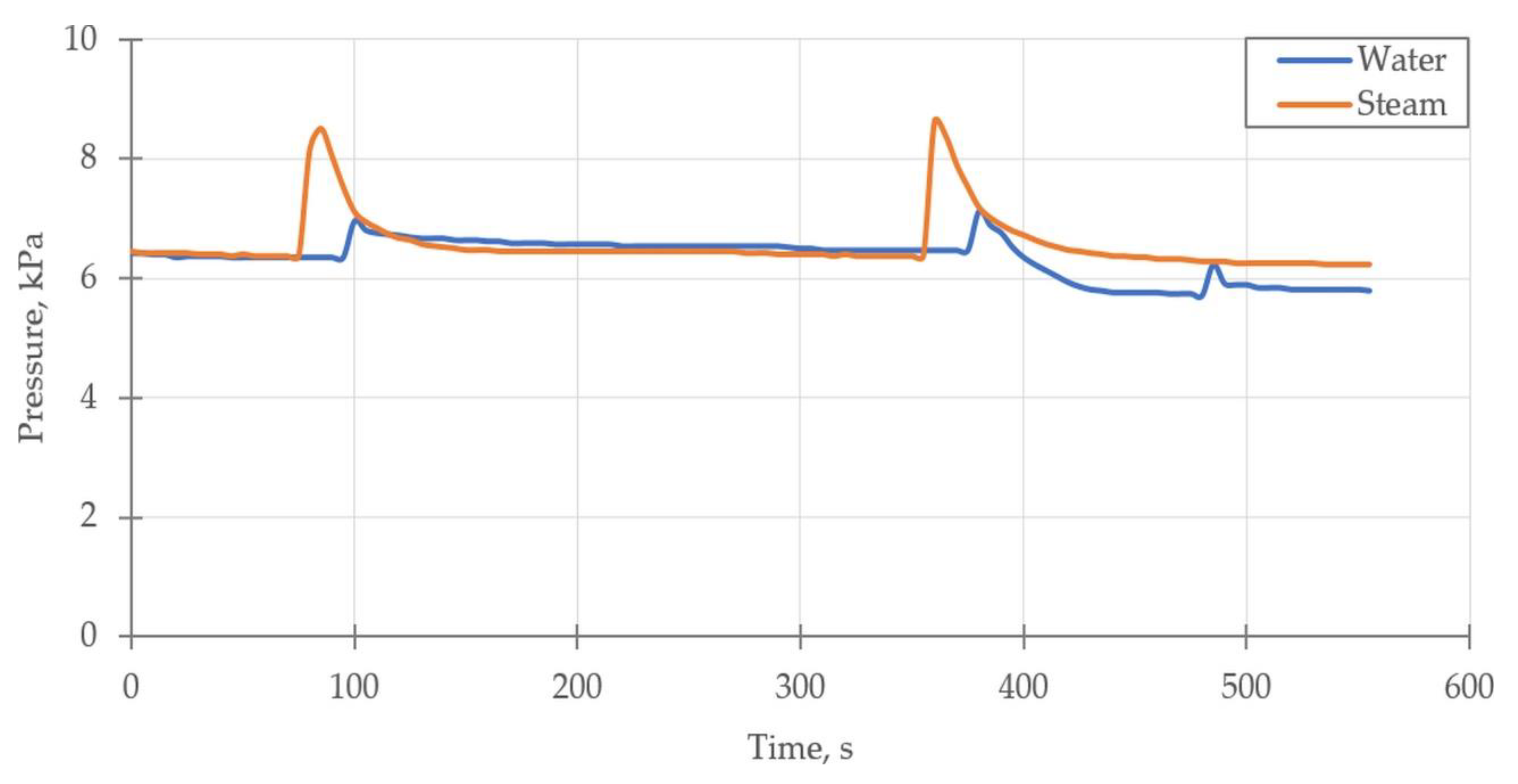
3.1. Preheating with Steam and Water
3.2. Cost Calculation
3.3. Challenges and Design Guidelines
- The steam supply system must be taken into account when designing new devices or, in the case of the existing ones, the adsorption chillers should be redesigned and rebuilt;
- An appropriate heat exchanger that enables the condensation of the steam should be designed or selected;
- Due to the condensation of steam, a heat exchanger should allow free drainage of the condensate and deaeration, which can be achieved by using straight pipes arranged parallelly and inclining the heat exchanger by about 3–5%;
- The steam inlet and water inlet should be on two sides of the heat exchanger to allow deaeration and condensate drainage;
- An appropriate heat exchanger and steam injection method that ensures uniform steam flow and reduces the vibrations should be designed or selected;
- Flow resistance during steam preheating is about 50 times greater than the flow resistance during water preheating. Therefore, it is advisable to increase the cross-sectional area of the pipes in the heat exchanger by at least 50%, which will result in a two-fold reduction in the flow resistance;
- The temperature difference between the steam and bed is about two times greater than the temperature difference between the heating water and bed. Additionally, the main barrier of heat transfer from the heating medium to the bed is the thermal contact resistance between the surface of the heat exchanger and silica gel grains [24]. Thus, changing the material of which the heat exchanger is made can be considered (e.g., from copper with high thermal conductivity to aluminum with lower thermal conductivity);
- Size reduction in the adsorption chiller, maintaining the same cooling capacity, should be kept in mind;
- The cost of preparing steam is about 10 times higher than the cost of preparing heating water using fossil fuels (Table 5). Thus, if there is a lack of waste steam from industry processes (or renewable energy sources), a thorough economic analysis should be conducted to ensure that using steam for bed preheating is cost-effective.
4. Conclusions
Author Contributions
Funding
Data Availability Statement
Conflicts of Interest
References
- Dupont, J.L.; Domanski, P.; Lebrun, P.; Ziegler, F. The Role of Refrigeration in the Global Economy. In Proceedings of the 38th Note on Refrigeration Technologies, International Institute of Refrigeration, Paris, France, 1 June 2019. [Google Scholar]
- International Energy Agency. Electricity Information: Overview. Available online: https://www.iea.org/reports/electricity-information-overview (accessed on 6 June 2021).
- El-Sayed, A.R.; El Morsi, M.; Mahmoud, N.A. A Review of the Potential Replacements of HCFC/HFCs Using Environment-Friendly Refrigerants. Int. J. Air-Cond. Refrig. 2018, 26, 1830002. [Google Scholar] [CrossRef]
- Regulation (EU) No 517/2014 of the European Parliament and of the Council of 16 April 2014 on Fluorinated Greenhouse Gases and Repealing Regulation (EC) No 842/2006. Available online: https://eur-lex.europa.eu/legal-content/EN/TXT/?uri=uriserv%3AOJ.L_.2014.150.01.0195.01.POL (accessed on 10 January 2020).
- UNESCO. The United Nations World Water Development Report 2018: Nature Based Solutions for Water; UNESCO: Paris, France, 2018. [Google Scholar]
- Nassrullah, H.; Anis, S.F.; Hashaikeh, R.; Hilal, N. Energy for desalination: A state-of-the-art review. Desalination 2020, 491. [Google Scholar] [CrossRef]
- Incropera, F.P.; DeWitt, D.P.; Bergman, T.L.; Lavine, A.S. Fundamentals of Heat and Mass Transfer; John Wiley & Sons: Hoboken, NJ, USA, 2007. [Google Scholar]
- Sharshir, S.W.; Elsheikh, A.H.; Peng, G.; Yang, N.; El-Samadony, M.O.A.; Kabeel, A.E. Thermal performance and exergy analysis of solar stills–A review. Renew. Sustain. Energy Rev. 2017, 73, 521–544. [Google Scholar] [CrossRef]
- Lu, Z.S.; Wang, R.Z. Performance improvement by mass-heat recovery of an innovative adsorption air-conditioner driven by 50–80 °C hot water. Appl. Therm. Eng. 2013, 55, 113–120. [Google Scholar] [CrossRef]
- Brückner, S.; Liu, S.; Miró, L.; Radspieler, M.; Cabeza, L.F.; Lävemann, E. Industrial waste heat recovery technologies: An economic analysis of heat transformation technologies. Appl. Energy 2015, 151, 157–167. [Google Scholar] [CrossRef]
- Alahmer, A.; Wang, X.; Alam, K.C.A. Dynamic and Economic Investigation of a Solar Thermal-Driven Two-Bed Adsorption Chiller under Perth Climatic Conditions. Energies 2020, 13, 1005. [Google Scholar] [CrossRef] [Green Version]
- Manila, M.R.; Mitra, S.; Dutta, P. Studies on dynamics of two-stage air cooled water/silica gel adsorption system. Appl. Therm. Eng. 2020, 178, 115552. [Google Scholar] [CrossRef]
- Du, S.W.; Li, X.H.; Yuan, Z.X.; Du, C.X.; Wang, W.C.; Liu, Z.B. Performance of solar adsorption refrigeration in system of SAPO-34 and ZSM-5 zeolite. Sol. Energy 2016, 138, 98–104. [Google Scholar] [CrossRef]
- Sha, A.A.; Baiju, V. Thermodynamic analysis and performance evaluation of activated carbon-ethanol two-bed solar adsorption cooling system. Int. J. Refrig. 2021, 123, 81–90. [Google Scholar] [CrossRef]
- Sztekler, K.; Kalawa, W.; Stefanski, S.; Krzywanski, J.; Grabowska, K.; Sosnowski, M.; Nowak, W.; Makowski, M. Using adsorption chillers for utilising waste heat from power plants. Therm. Sci. 2019, 23, S1143–S1151. [Google Scholar] [CrossRef] [Green Version]
- Sah, R.P.; Choudhury, B.; Das, R.K. A review on adsorption cooling systems with silica gel and carbon as adsorbents. Renew. Sustain. Energy Rev. 2015, 45, 123–134. [Google Scholar] [CrossRef]
- Boruta, P.; Bujok, T.; Mika, Ł. Adsorbents, Working Pairs and Coated Beds for Natural Refrigerants in Adsorption Chillers—State of the Art. Energies 2021, 14, 4707. [Google Scholar] [CrossRef]
- Sztekler, K.; Kalawa, W.; Nowak, W.; Mika, L.; Gradziel, S.; Krzywanski, J.; Radomska, E. Experimental study of three-bed adsorption chiller with desalination function. Energies 2020, 13, 5827. [Google Scholar] [CrossRef]
- Jribi, S.; Saha, B.B.; Koyama, S.; Bentaher, H. Modeling and simulation of an activated carbon–CO2 four bed based adsorption cooling system. Energy Convers. Manag. 2014, 78, 985–991. [Google Scholar] [CrossRef]
- Saha, B.B.; Koyama, S.; Kashiwagi, T.; Akisawa, A.; Ng, K.C.; Chua, H.T. Waste heat driven dual-mode, multi-stage, multi-bed regenerative adsorption system. Int. J. Refrig. 2003, 26, 749–757. [Google Scholar] [CrossRef]
- Sztekler, K. Optimisation of Operation of Adsorption Chiller with Desalination Function. Energies 2021, 14, 2668. [Google Scholar] [CrossRef]
- Ng, K.C.; Wang, X.; Lim, Y.S.; Saha, B.B.; Chakarborty, A.; Koyama, S.; Akisawa, A.; Kashiwagi, T. Experimental study on performance improvement of a four-bed adsorption chiller by using heat and mass recovery. Int. J. Heat Mass Transf. 2006, 49, 3343–3348. [Google Scholar] [CrossRef]
- Chekirou, W.; Boukheit, N.; Karaali, A. Heat recovery process in an adsorption refrigeration machine. Int. J. Hydrogen Energy 2016, 41, 7146–7157. [Google Scholar] [CrossRef]
- Rezk, A.; Al-Dadah, R.K.; Mahmoud, S.; Elsayed, A. Effects of contact resistance and metal additives in finned-tube adsorbent beds on the performance of silica gel/water adsorption chiller. Appl. Therm. Eng. 2013, 53, 278–284. [Google Scholar] [CrossRef]
- Grabowska, K.; Krzywanski, J.; Nowak, W.; Wesolowska, M. Construction of an innovative adsorbent bed configuration in the adsorption chiller-Selection criteria for effective sorbent-glue pair. Energy 2018, 151, 317–323. [Google Scholar] [CrossRef]
- Sharafian, A.; Bahrami, M. Assessment of adsorber bed designs in waste-heat driven adsorption cooling systems for vehicle air conditioning and refrigeration. Renew. Sustain. Energy Rev. 2014, 30, 440–451. [Google Scholar] [CrossRef]
- Cao, N.V.; Duong, X.Q.; Lee, W.S.; Park, M.Y.; Chung, J.D.; Hong, H. Effect of heat exchanger materials on the performance of adsorption chiller. J. Mech. Sci. Technol. 2020, 34, 2217–2223. [Google Scholar] [CrossRef]
- Bahrehmand, H.; Khajehpour, M.; Bahrami, M. Finding optimal conductive additive content to enhance the performance of coated sorption beds: An experimental study. Appl. Therm. Eng. 2018, 143, 308–315. [Google Scholar] [CrossRef]
- Kulakowska, A.; Pajdak, A.; Krzywanski, J.; Grabowska, K.; Zylka, A.; Sosnowski, M.; Wesolowska, M.; Sztekler, K.; Nowak, W. Effect of Metal and Carbon Nanotube Additives on the Thermal Diffusivity of a Silica Gel-Based Adsorption Bed. Energies 2020, 13, 1391. [Google Scholar] [CrossRef] [Green Version]
- Sztekler, K.; Kalawa, W.; Mika, Ł.; Mlonka-Medrala, A.; Sowa, M.; Nowak, W. Effect of Additives on the Sorption Kinetics of a Silica Gel Bed in Adsorption Chiller. Energies 2021, 14, 1083. [Google Scholar] [CrossRef]
- Szyc, M.; Nowak, W. Operation of an adsorption chiller in different cycle time conditions. Chem. Process Eng. 2014, 35, 109–119. [Google Scholar] [CrossRef] [Green Version]
- Ghilen, N.; Gabsi, S.; Benelmir, R.; Ganaoui, M. El Performance Simulation of Two-Bed Adsorption Refrigeration Chiller with Mass Recovery. J. Fundam. Renew. Energy Appl. 2017, 7. [Google Scholar] [CrossRef]
- Sekret, R.; Turski, M. Research on an adsorption cooling system supplied by solar energy. Energy Build. 2012, 51, 15–20. [Google Scholar] [CrossRef]
- Grzebielec, A.; Rusowicz, A.; Laskowski, R. Experimental Study On Thermal Wave Type Adsorption Refrigeration System Working On A Pair Of Activated Carbon And Methanol. Chem. Process Eng. 2015, 36, 395–404. [Google Scholar] [CrossRef]
- Schwamberger, V.; Desai, A.; Schmidt, F.P. Novel Adsorption Cycle for High-Efficiency Adsorption Heat Pumps and Chillers: Modeling and Simulation Results. Energies 2019, 13, 19. [Google Scholar] [CrossRef] [Green Version]
- Ng, K.C.; Thu, K.; Kim, Y.; Chakraborty, A.; Amy, G. Adsorption desalination: An emerging low-cost thermal desalination method. Desalination 2013, 308, 161–179. [Google Scholar] [CrossRef]
- Shahzad, M.W.; Ybyraiymkul, D.; Burhan, M.; Oh, S.J.; Ng, K.C. An innovative pressure swing adsorption cycle. AIP Conf. Proc. 2019, 2062. [Google Scholar] [CrossRef]
- Taylor, J.R. An Introduction to Error Analysis. The Study of Uncertainties in Physical Mesurements, 2nd ed.; University Science Books: Sausalito, CA, USA, 1997. [Google Scholar]
- Sztekler, K.; Kalawa, W.; Nowak, W.; Mika, L.; Grabowska, K.; Krzywanski, J.; Sosnowski, M.; Al-Harbi, A.A. Performance evaluation of a single-stage two-bed adsorption chiller with desalination function. J. Energy Resour. Technol. 2020, 143, 082101. [Google Scholar] [CrossRef]
- Ng, K.C.; Chua, H.T.; Chung, C.Y.; Loke, C.H.; Kashiwagi, T.; Akisawa, A.; Saha, B.B. Experimental investigation of the silica gel-water adsorption isotherm characteristics. Appl. Therm. Eng. 2001, 21, 1631–1642. [Google Scholar] [CrossRef]
- The National Centre for Emissions Management. Wartości opałowe (WO) i Wskaźniki Emisji CO2 (WE) w roku 2018 do Raportowania w Ramach Systemu Handlu Uprawnieniami do Emisji za rok 2021; The National Centre for Emissions Management: Warszawa, Polska, 2020. [Google Scholar]


| Desalination Technology | Electrical Energy Consumption, kWh/m3 | Thermal Energy Consumption, kWh/m3 | Cost, USD/m3 | Heat Source Temperature, °C |
|---|---|---|---|---|
| Adsorption chiller | 1.4 | 39.8 | 0.7 | 55–85 |
| Multi-stage flash desalination | 2.5–5.0 | 81.0–144.0 | 1–5 | 90–110 |
| Multi-effect distillation | 1.5–2.0 | 60.0–70.0 | 2–9 | 79–90 |
| Passive solar still | 0 | 1106 1 | 1.3–6.5 | - |
| Reverse osmosis | 41–45 | 0 | 3–27 | - |
| Parameter | Value |
|---|---|
| Maximum heating power | 14 kW |
| Steam output | 18.5 kg/h |
| Supply voltage | 230 V |
| Boiler capacity | 24.9 L |
| Maximum steam pressure | 7 bar |
| Water pump motor power | 0.55 kW |
| Parameter | Sensor | Measurement Range | Measurement Uncertainty |
|---|---|---|---|
| Temperature | Pt-100 1 Pt-1000 | −80 °C to 250 °C −80 °C to 150 °C | ±0.1 °C ±0.1 °C |
| Pressure | Pressure transducer | 0–99 kPa | ±0.5% |
| Flow rate | Electromagnetic flow meter | 1–100 L/min | ±0.5% |
| Parameter | Variant 1 (Water Preheating) | Variant 2 (Steam Preheating) | |
|---|---|---|---|
| Evaporator | Cooling capacity | 1.10 kW | 1.10 kW |
| The chilled water inlet temperature T1 | 20 °C | 20 °C | |
| The chilled water outlet temperature T2 | 18 °C | 18 °C | |
| The chilled water mass flow rate F1 | 0.125 kg/s | 0.125 kg/s | |
| Condenser | Capacity | 2.00 kW | 2.00 kW |
| The cooling water inlet temperature T3 | 25 °C | 25 °C | |
| The cooling water outlet temperature T4 | 27 °C | 27 °C | |
| The cooling water mass flow rate F2 | 0.250 kg/s | 0.250 kg/s | |
| Beds | The heating water inlet temperature T5 | 80 °C | 80 °C |
| The heating water mass flow rate F3 | 0.250 kg/s | 0.250 kg/s | |
| Steam inlet temperature T5 | - | 120 °C | |
| Steam inlet pressure P1 | - | 1.864 bar | |
| Steam outlet pressure P2 | - | 1.386 bar | |
| Steam mass flow rate F3 | - | 0.0021 kg/s | |
| The cooling water inlet temperature T6 | 25 °C | 25 °C | |
| Mass of the sorbent | 12 kg | 12 kg | |
| Cycle time | Preheating | 50 | 50 |
| Adsorption/desorption | 300 | 300 | |
| Heat recovery | 30 | 30 |
| Fuel | Calorific Value, (kJ/kg) | Unit Price, (PLN/kg) | Cost of Generating the Steam, (PLN/kg) | Cost of Preparing the Heating Water, (PLN/kg) |
|---|---|---|---|---|
| Black coal | 21,240 | 0.89 | 0.11 | 0.01 |
| Lignite | 9470 | 0.30 | 0.08 | 0.01 |
| Oil | 42,300 | 3.02 | 0.19 | 0.02 |
| Natural gas | 48,000 | 1805.56 | 98.63 | 9.45 |
| Waste steam from industrial processes | - | 0 | 0 | - |
Publisher’s Note: MDPI stays neutral with regard to jurisdictional claims in published maps and institutional affiliations. |
© 2021 by the authors. Licensee MDPI, Basel, Switzerland. This article is an open access article distributed under the terms and conditions of the Creative Commons Attribution (CC BY) license (https://creativecommons.org/licenses/by/4.0/).
Share and Cite
Sztekler, K.; Kalawa, W.; Mika, L.; Lis, L.; Radomska, E.; Nowak, W. The Effects of Using Steam to Preheat the Beds of an Adsorption Chiller with Desalination Function. Energies 2021, 14, 6454. https://0-doi-org.brum.beds.ac.uk/10.3390/en14206454
Sztekler K, Kalawa W, Mika L, Lis L, Radomska E, Nowak W. The Effects of Using Steam to Preheat the Beds of an Adsorption Chiller with Desalination Function. Energies. 2021; 14(20):6454. https://0-doi-org.brum.beds.ac.uk/10.3390/en14206454
Chicago/Turabian StyleSztekler, Karol, Wojciech Kalawa, Lukasz Mika, Lukasz Lis, Ewelina Radomska, and Wojciech Nowak. 2021. "The Effects of Using Steam to Preheat the Beds of an Adsorption Chiller with Desalination Function" Energies 14, no. 20: 6454. https://0-doi-org.brum.beds.ac.uk/10.3390/en14206454