
Combustion of Fuel Surrogates: An Application to Gas Turbine Engines


1
Institute for Future Transport and Cities, Coventry University, Coventry CV1 5FB, UK
2
Faculty of Engineering, Environment and Computing, School of Mechanical, Aerospace and Automotive Engineering, Coventry University, Coventry CV1 2JH, UK
3
Mechanical Engineering and Design, Faculty of Arts, Science and Technology, University of Northampton, Northampton NN1 5PH, UK
4
Department of Mechanical Engineering, Engineering Faculty, Esentepe Campus, Sakarya University, Serdivan 54050, Turkey
5
Team-SAN Ltd., Serdivan 54050, Turkey
*
Author to whom correspondence should be addressed.
Energies 2021, 14(20), 6545; https://0-doi-org.brum.beds.ac.uk/10.3390/en14206545
Submission received: 1 September 2021
/
Revised: 1 October 2021
/
Accepted: 6 October 2021
/
Published: 12 October 2021
(This article belongs to the Special Issue Biodiesel Fuel Combustion)
Abstract
:The previously developed approaches for fuel droplet heating and evaporation processes, mainly using the Discrete Multi Component Model (DMCM), are investigated for the aerodynamic combustion simulation. The models have been recently improved and generalised for a broad range of bio-fossil fuel blends so that the application areas are broadened with an increased accuracy. The main distinctive features of these models are that they consider the impacts of species’ thermal conductivities and diffusivities within the droplets in order to account for the temperature gradient, transient diffusion of species and recirculation. A formulation of fuel surrogates is made using the recently introduced model, referred to as “Complex Fuel Surrogate Model (CFSM)”, and analysing their heating, evaporation and combustion characteristics. The CFSM is aimed to reduce the full composition of fuel to a much smaller number of components based on their mass fractions, and to formulate fuel surrogates. Such an approach has provided a proof of concept with the implementation of the developed model into a commercial CFD code ANSYS Fluent. A case study is made for the CFD modelling of a gas turbine engine using a kerosene fuel surrogate, which is the first of its kind. The surrogate is proposed using the CFSM, with the aim to reduce the computational time and improve the simulation accuracy of the CFD model.
1. Introduction
Energy demand is sharply increasing along with the increase in the worldwide population and global fossil fuel consumption. This demand is expected to grow at an average annual growth rate of around 1% [1]. Currently, more than 99% of the transport sector is powered by combustion engines, which contribute to around 14% of Greenhouse Gas Emissions (GGE) [1,2]. Due to the depletion of fossil fuels, governments and industries are aiming to shift from the dependency on fossil fuels to renewable energy sources (e.g., biofuels) [3,4,5]. The use of a mixture of biofuels (e.g., biodiesel and ethanol) with fossil fuels in standard propulsion systems can reduce GGE and lead to complete combustion [6]. According to the US Environmental Protection Agency, all gasoline engine vehicles can use a blend of gasoline fuel with up to a 10% volume fraction of ethanol without the need for engine modification [7]. The reduction in CO2 emissions without a loss of engine performance is noticeable for this mixture [8]. According to the European Renewable Ethanol Association, replacing European gasoline with a mixture of 10% ethanol and 90% gasoline (known as E10) would reduce the GGE by 6% [9]. Mixtures with up to 15% of ethanol and 85% of gasoline fuel have been approved for use in 2001 and newer vehicles, under the U.S. federal standards for renewable fuel [10]. Unsurprisingly, this increase in the ethanol content in the baseline fuel would reduce the GGE even further. For diesel fuel, it is known that mixtures with up to 85% diesel and 15% ethanol are used in standard diesel engines without significant impacts on these engines [11]. In addition, it has been reported in [12] that ethanol can be blended with diesel fuel at up to 20% ethanol.
Based on the scientific ground of the applicability of bio-fossil fuel blends in conventional gasoline and diesel engines [13], governments set targets for the use of biofuels by increasing their fractions in the baseline fuel (gasoline and diesel). According to the UK Department for Transport, the British government has legislated a new policy for increasing the percentage of bio/fossil fuel blends from 4.75% in 2018 to 9.75% in 2020 and to 12.4% in 2032 in order to achieve its obligations regarding reducing the GGE by 6% by the end of 2020 [14]. Recently, the US administration gave approval for the compulsory use of E15 [15].
The importance of the multi-component fuel droplets heating, and evaporation processes has been highlighted in literature [13,16,17]. These processes precede the onset of ignition, and play an essential role in the performance of engines due to their very short time before the ignition of the air/fuel mixture [18]. Incomplete combustion and high levels of pollutant are expected when the fuel is not well mixed with air and completely evaporated. As such, understanding these processes is crucial to the design and optimum operation of engine. Different models were developed for the simulation of multi-component fuel droplet heating and evaporation [19,20,21,22]. In most cases, the modelling of heating and evaporation of multi-component droplets were represented by single components; for instance, gasoline was represented by iso-octane [23] and diesel was represented by n-dodecane [24,25]. These approaches were based on two assumptions: (1) the effect of species diffusion inside droplets during the evaporation process and (2) the effect of finite thermal conductivity with droplets could be ignored. Most of these studies (e.g., [26,27]) relied on these assumptions to reduce the model complexity and the computational cost (CPU time).
The importance of considering the effect of species diffusion inside droplets and finite thermal conductivity was highlighted in many studies, and they were modelled using the Effective Thermal Conductivity/Effective Diffusivity (ETC/ED) models [28,29,30]. The importance of the latter models was represented by the fact that they considered the recirculation, temperature gradient and species diffusion inside droplets. Recent models were developed to consider ETC/ED models, including the Discrete Multi-Component Model (DMCM), Quasi-Discrete Model (QDM) and Multi-Dimensional Quasi-Discrete Model (MDQDM). The combustion studies were always based on the approximation of the composition of a fuel by a certain number of components to match the real combustion characteristics of the fuel [31,32]. These approximations, commonly known as fuel surrogates, were mainly used due to the unavailability of the chemical mechanisms of many components and the lack of computational resources. Although fuel surrogates were good representatives of the real fuel composition in terms of their chemical behaviour, these surrogates might not be able to match the physical characteristics of that fuel.
In this analysis, the suggested kerosene fuel surrogate is examined in terms of heating and evaporation using the implemented CFSM into ANSYS Fluent via the User-Defined Function (UDF). The use of surrogates in CFD analysis can make a good representation of the fuel composition, with a minimum sacrifice in the computational efficiency. The model has been validated in comparison to experimental measurements, and the simulation accuracy is investigated in comparison to standard CFD data. Finally, the ignition time delay of the suggested surrogate is predicted and compared to those of the fuel composition of the kerosene and ANSYS kerosene suggested surrogate.
2. Method
In this analysis, kerosene fuel surrogate is inferred from [33] and formulated using the complex fuel surrogate (CFS) model in [34]. The formulated surrogate is then compared with the kerosene surrogate provided in the commercial CFD software tool ANSYS Fluent. The CFS in [34] was based on the effective Thermal Conductivity and Effective Diffusivity (ETC/ED) models. These models were described in [35,36]. The transient heat and species diffusion equations are solved analytically for a spherically symmetric droplet [37]:
where is temperature ; is the liquid thermal diffusivity, , and are the liquid density, liquid thermal conductivity and specific heat capacity, respectively; is the distance from the droplet centre; is time; is the mass fraction of species ; is the liquid species diffusivity calculated using the Wilke–Chang approximation [38]. The thermal and mass diffusivities were replaced by the effective thermal/mass diffusivity to consider the recirculation inside the liquid droplet. The droplet mass evaporation rate, , is calculated as:
where is the density of the mixture of vapour and air, assumed to be independent of the distance from the droplet surface, is the Spalding mass transfer number, is the isolated droplet’s Sherwood number estimated following Sirignano [39] and is the vapour binary diffusion coefficient calculated using the Wilke–Lee formula [40].
In [34], the carbon number of each Approximate Discrete Component (ADC) generated by the CFSM was introduced as:
where refers to the hydrocarbon group number in the fuel, is the carbon number of the component in group and is the mass fraction of the component in group. The nearest integer of the carbon number (ADC) was determined in Equation (4). In addition, we used the mass fractions (instead of the molar fractions) to calculate the ADC group averaged carbon number . These mass fractions were used to demonstrate the importance of heavy components on the expense of less important (lighter) ones for the prediction of droplet lifetime. For example, alkanes (the heaviest group) make up to 44.53% of diesel mass fractions (only 41.48% diesel molar fractions), which dominates the fuel composition at the expense of lighter components—such as naphthalenes, with up to 7.46% mass fractions (9% molar fractions), and alkylbenzenes, with up to 13.62% mass fractions (16.75 molar fractions).
The integer ADCs were generated within each group, where were the start and end counted components of the grouped species, respectively, and for the second grouped components was.
The ignition time delays of kerosene surrogates were estimated at different combustion temperatures, pressures, and equivalence ratios. The Arrhenius relationships of ignition time delay suggested in [41] for RP-3 kerosene was used for the suggested surrogate (53.4% iso-decane and 46.6% cyclododecane) using the appropriate activation energy. The relationships can be expressed as [42]:
where is the pressure in Pa,is the equivalence ratio (fuel/air ratio), is the activation energy, which is 134.68 kJ/mol, is the universal gas constant in kJ/mol. K and is the oxidation temperature in K. The ignition time delay of the suggested kerosene surrogate was compared to the full composition of kerosene fuel. The ignition time delay of the latter one was estimated based on a modified form of the Arrhenius relationships (using the appropriate activation energy), recommended for a multi-component kerosene of n-decane, n-dodecane, isocetane, methylcyclohexane and toluene with a molar fraction of 14%, 10%, 30%, 36% and 10%, respectively. Further details on this expression can be found in [42]:
The for the kerosene fuel is 132.8 kJ/mole.
3. Fuel Composition
The Complex Fuel Surrogate Model (CFSM), which has been discussed and presented in detail in earlier studies (e.g., [34,43]), was used for the formulation of the kerosene surrogate [44]. The composition of the full kerosene is shown in Table 1.
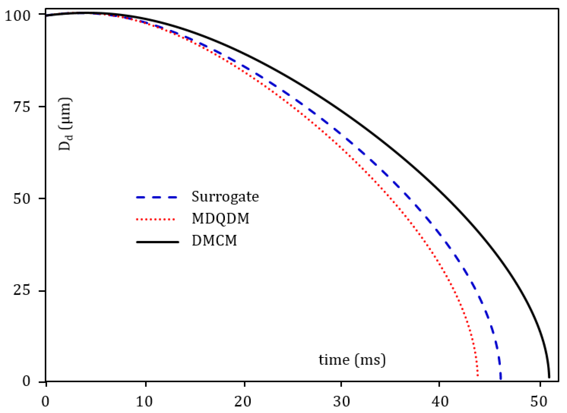
The composition shown in Table 1 was investigated in terms of heating and evaporation using the DMCM. The CFSM was then used to generate a surrogate for the kerosene fuel. The CFSM was limited for two Approximate Discrete Components (ADC) (i.e., the generated surrogate consisted of two components only). This limit in the number of components was because the generated surrogate was later used for combustion studies using detailed chemical mechanisms. The two generated ADC were iso-decane and cyclododecane , with fractions of 0.534 and 0.466, respectively. These two components with their fractions represent the suggested surrogate for kerosene. The evolutions of the droplet diameter for the suggested surrogate, using the CFSM, were compared with the predictions of the Multi-Dimensional Quasi-Discrete Model (MDQDM) and DMCM (Figure 1). For this comparison, a single droplet was considered using some typical gas turbine conditions. The initial droplet diameter and temperature were 100 µm and 375 K, respectively. The ambient gas temperature and pressure were 800 K and 0.4 MPa, respectively.
Compared to the full composition, the suggested surrogate shows a 7.6% deviation. This deviation can be well reduced if only one extra component was considered for the surrogate. For the implementation and combustions studies, however, this deviation is acceptable in order to maintain no more than two components.
4. Pre-Combustion Analysis
The main reason behind the implementation of the DMCM model into ANSYS Fluent is due to the fact that the latter software tool does not take into account several factors for the droplet heating and evaporation, e.g., the temperature gradient, diffusion of species and internal recirculation inside moving droplets. Instead, it is based on the assumption that all of these factors can be ignored. The reasons behind these simplifications were discussed in [45]. The work presented in [46] was the first work that investigated the implementation of a model for droplet heating and evaporation by accounting for the temperature gradient inside the droplet. The work of [46] was for a mono-component. This work was then generalised in [47] for the case of binary components, in which, the diffusion of species was also considered, combined with the temperature gradient inside the droplet. The latter work, however, was conducted for cooling evaporation, in which, the droplet was left in the ambient for evaporation. Furthermore, no full evaporation was observed.
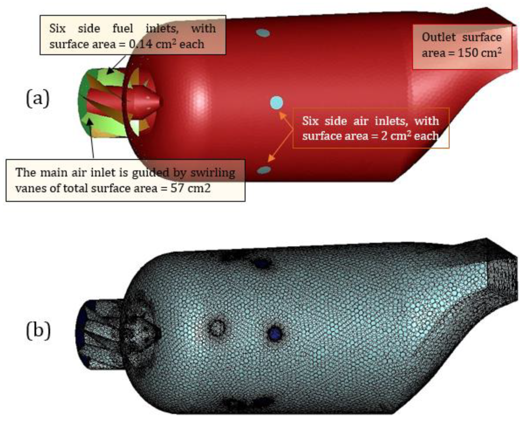
In this proof-of-concept work, the thesis finding of CFSM was implemented into a commercial CFD code with an attempt to simulate the gas turbine combustion processes. A detailed analysis of the heating and evaporation of the generated kerosene fuel surrogate was implemented into the 3D CFD model. The implemented heating and evaporation model takes into account the temperature gradient, species diffusion and recirculation inside droplets. Such an approach is the first of its kind for any former literature work. This was achieved via the implementation of the DMCM into ANSYS Fluent using the UDF. The heating and evaporation were assumed to take place in a can-type combustor. The computational domain and polyhedral mesh used for the hydrodynamic model are shown in Figure 2.
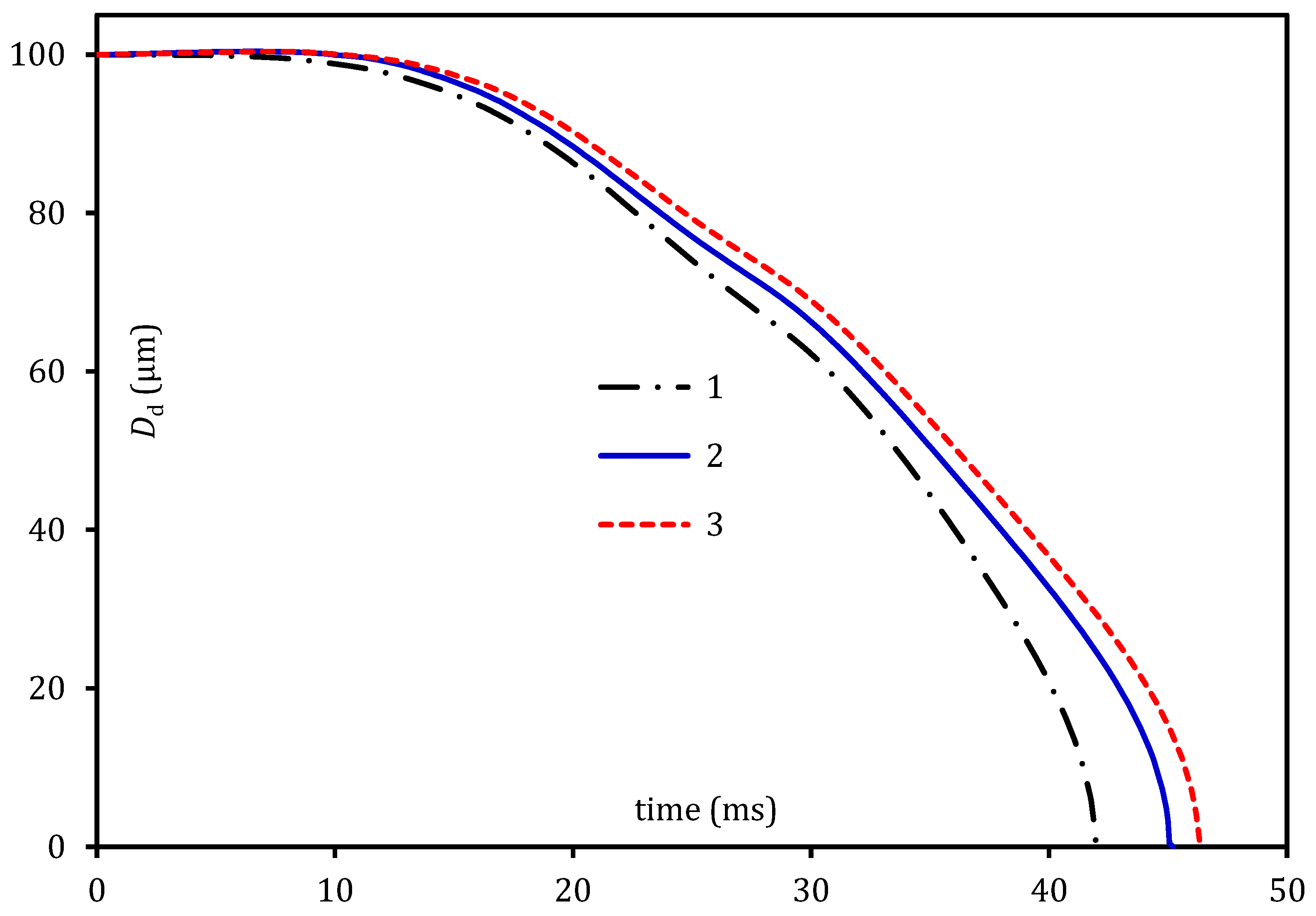
The droplet lifetime predicted by the new ANSYS CFD model was assessed in comparison to the original in-house code for a diameter droplet moving in stationary air at . The initial fuel temperature was under the ambient air temperature and a pressure of and , respectively. In Figure 2, the evolution of the droplet diameter with time is presented using three approaches: (1) the results predicted by standard ANSYS Fluent software using constant properties; (2) the results predicted by ANSYS Fluent and transient properties of fuel components using the UDF, but without the CFSM; and (3) ANSYS Fluent results with the full implementation of the CFSM and transient thermodynamic and transport properties.
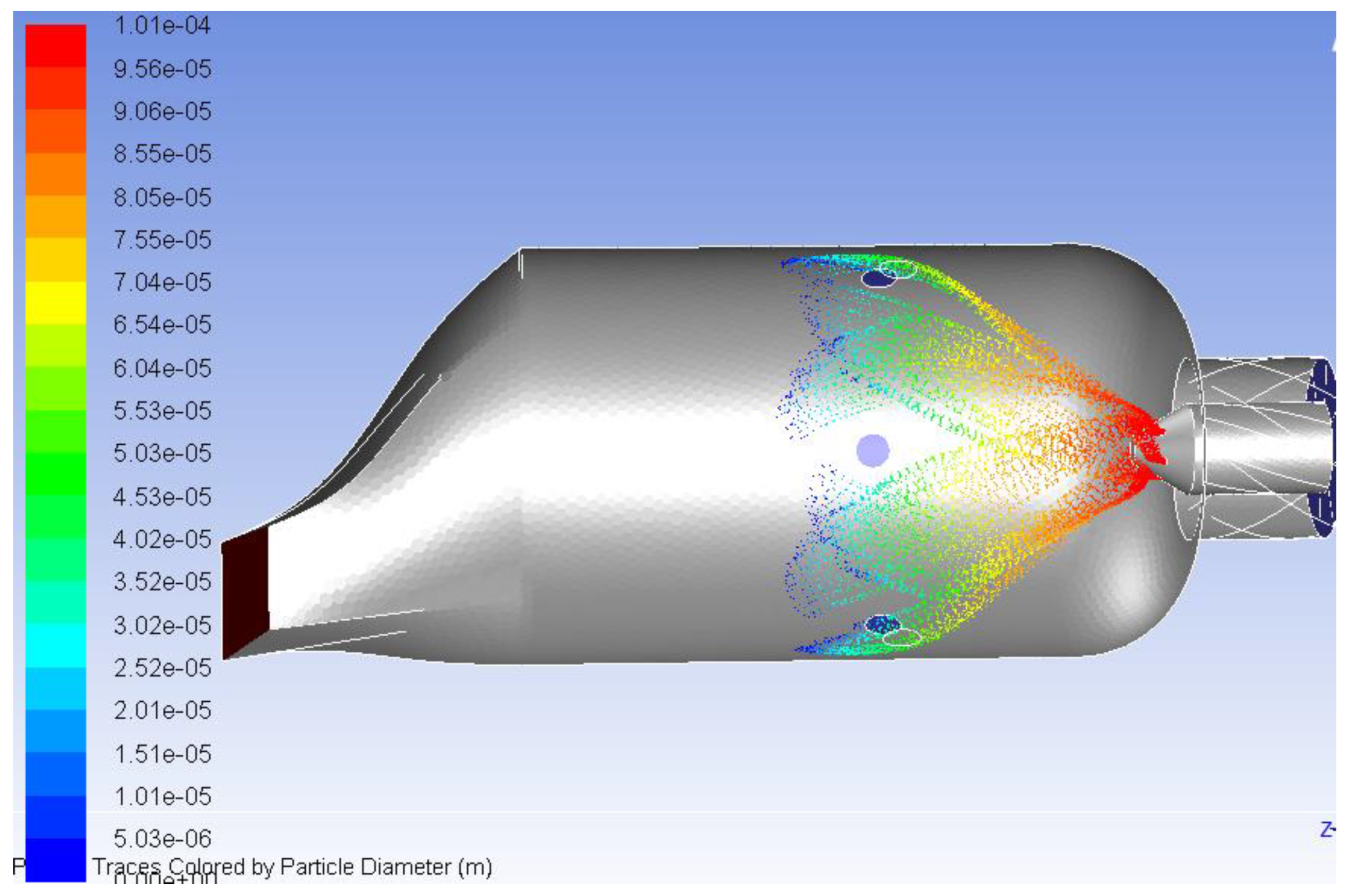
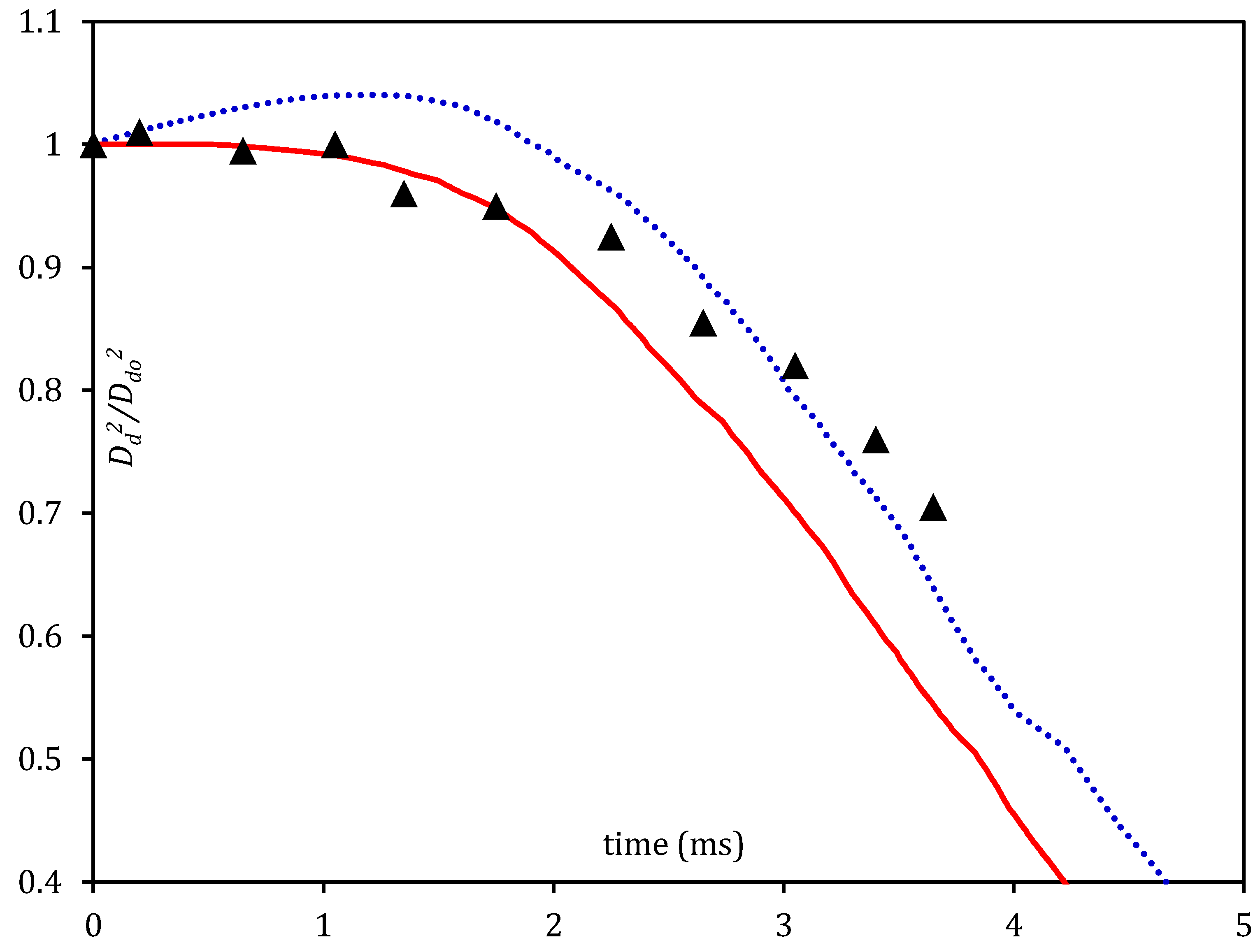
As follows from Figure 3, the incorporation of the DMCM into ANSYS Fluent leads to a prediction of up to 10.4% longer evaporation times compared to the case when the standard ANSYS Fluent model is used. A contour of the droplet evaporation inside the can combustor is shown in Figure 4. As can be seen from that figure, all droplets are injected at a diameter of , and all of these droplets are evaporated at around a distance of 40% of the injection point. The results validating the ANSYS Fluent simulation that incorporated the new model is presented in Figure 5. The validation was carried out by comparing the computed results with experimental data reported in the literature [48]. This was based on a kerosene droplet with an initial diameter of 1.8 mm and initial temperature of 298 K. The droplet was exposed to an air flow rate of 20 L/min at 0.1 MPa ambient pressure. As can be seen from Figure 3, there is a general agreement between the numerical results and experimental data. In the CFSM analyses, the effect of thermal swelling on droplet heating and evaporation was taken into account.
5. Combustion Analysis
The combustion characteristics of the suggested surrogate (53.4% iso-decane and 46.6% cyclododecane) were also compared with the simulated results of a suggested kerosene surrogate in ANSYS. The latter surrogate consists of one hypothetical component (C12H23), which does not exist in real life. The combustion of the surrogates was investigated based on the partially premixed combustion model with FGM state relation for a diffusion flamelet and a non-adiabatic system. A co-axial air-blast atomiser was used with primary and secondary air and fuel mass flowrates of 0.15, 0.025 and 0.003 kg/s, respectively. The main input parameters for the simulation are presented in Table 2.
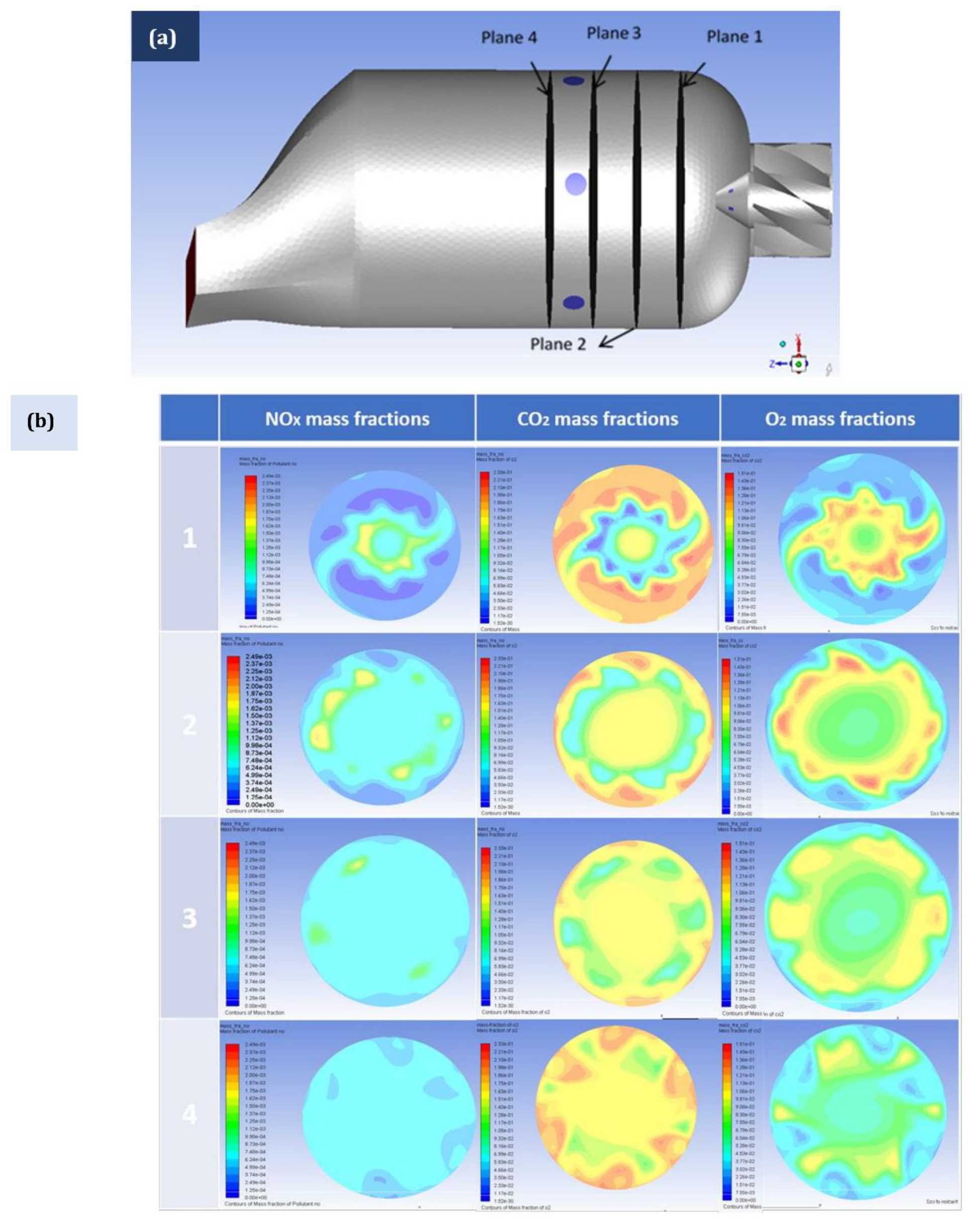
A realizable turbulence model was used for the hydrodynamic region with enhanced wall treatment. The combustion mechanism of iso-decane and cyclododecane (components of the suggested surrogate) were imported from [49]. The chemical mechanisms of iso-decane and cyclododecane were merged together using ANSYS Chemkin. The resulting chemical mechanism of the two components included 194 species with 1459 reactions. The domain pressure and velocity were coupled in a quasi-transient manner. The chemical reaction model showed a homogeneous combustion. Further illustrations of the combustion species formation inside the can combustor, and at various sections along its length, are provided in Figure 6, Figure 7 and Figure 8.
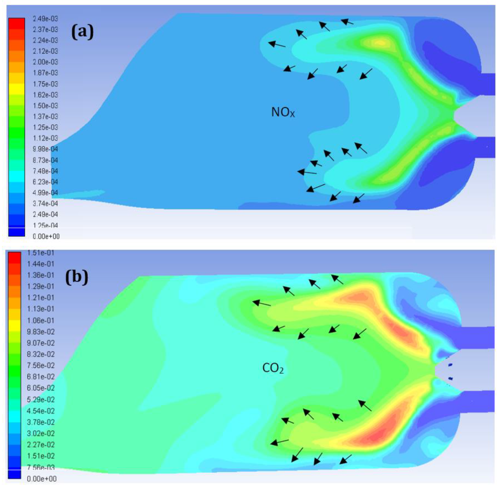
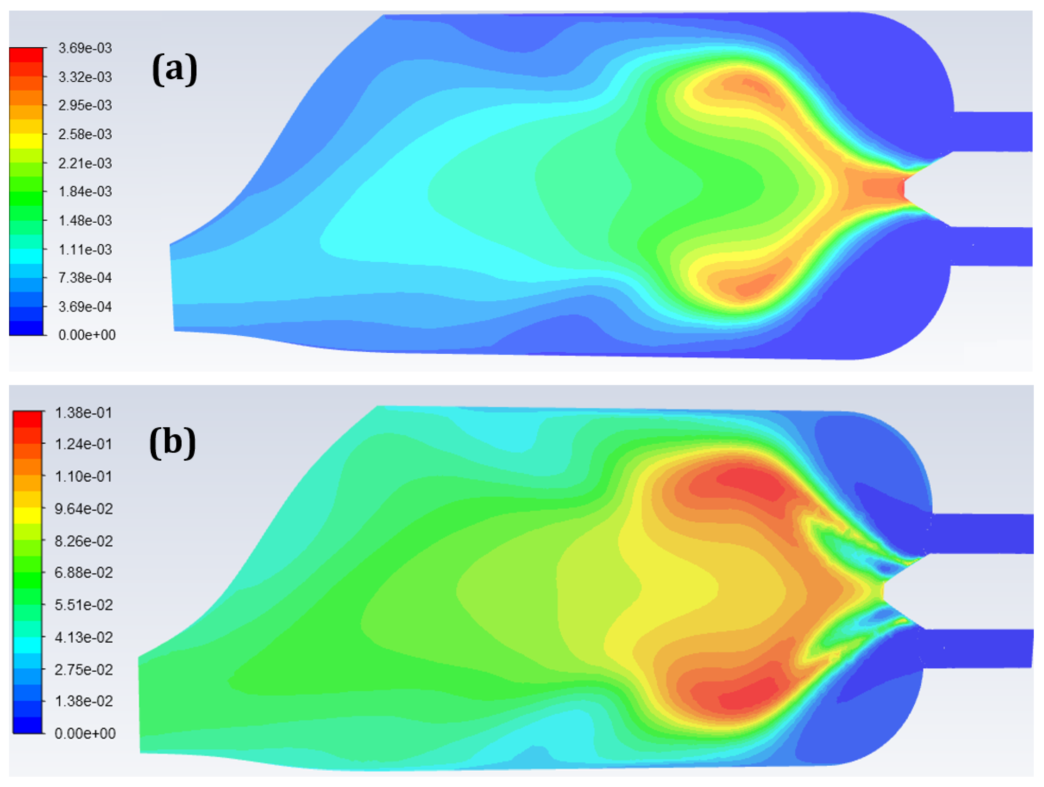
As can be seen from Figure 6, the entrainment of air flow enhances the oxidation of the mixture (suggested surrogate and air) with charge from the dilution holes. The NOX, and CO2 are at a relatively low level, indicating well-diluted fuel leading to a complete combustion. The above results were obtained for the suggested surrogate. The species distributions were also obtained for the ANSYS kerosene surrogate. The distribution of NOX and CO2 are shown in Figure 7. It can be seen that the implementation of the detailed combustion chemistry of the suggested kerosene surrogate can lead to lower NOX and CO2. This is attributed to the combustion chemistry of the ANSYS kerosene surrogate, which does not include a detailed species generated because of the combustion process. Instead, it includes only 20 species (N2, O2, C12H23, CO, CO2, H2O, H2, C, OH, CH4, H, O, HO2, H2O2, HCO, CHO, NO, HOCO, C2H6 and HCOOH). Hence, the mass fractions of NOX and CO2 are higher than those of the suggested surrogate (using the CFSM) with the detailed combustion chemistry.
The thermodynamic characteristics of the combustion process of the suggested surrogate and ANSYS surrogate are presented in Table 3. A noticeable difference between the two surrogates is observed. The thermodynamic characteristics of the ANSYS surrogate are always higher because, on average, this surrogate is heavier than the suggested surrogate.
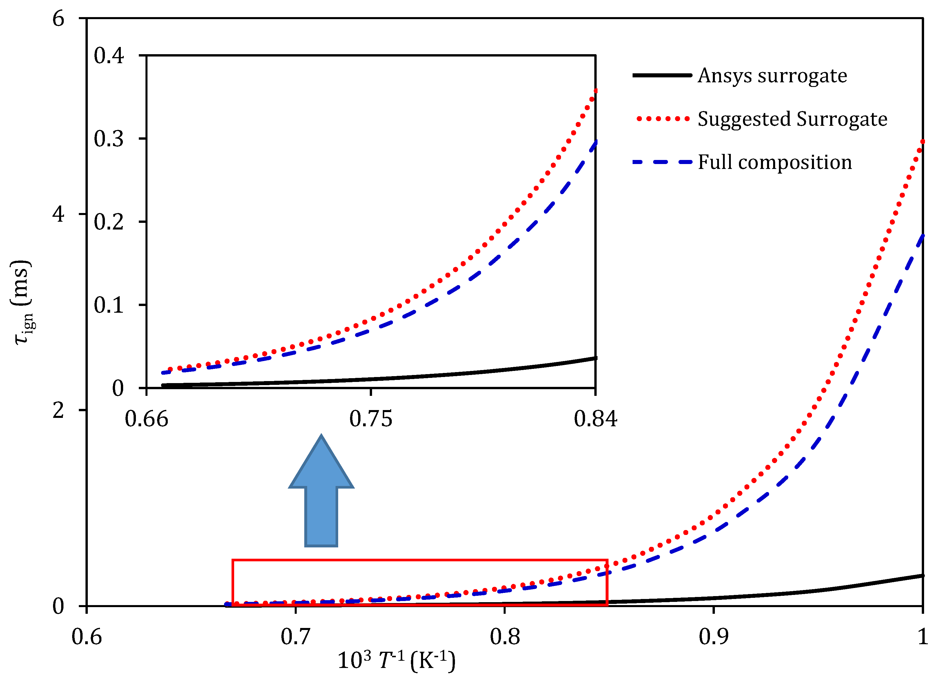
A comparison between the ignition time delay (τign) of the full composition of the kerosene fuel and the two surrogates (suggested surrogate and ANSYS surrogate) is presented in Figure 9. The analysis is conducted at an ambient pressure of 0.4 MPa, an equivalence ratio of 1 and an oxidation temperature range of 1000–1500 K. The prediction of the ignition time delays of the fuel and its suggested surrogate are very close at the high oxidation temperature. However, a significant difference is noticed at the low oxidation temperature. To improve the predictions of the ignition time delay at the low oxidation temperature, a surrogate with a higher number of components is possibly needed. The ignition time delay of the surrogate suggested in ANSYS deviates significantly from that of the full composition of kerosene fuel. The main reason behind that deviation is that the activation energy of the ANSYS surrogate is noticeably low (118 kJ/mole).
Based on the results obtained above, one can say that formulated surrogates should include a higher number of components (not only two as suggested) in order to improve the prediction’s accuracy. This vision can be true to a limited extent, since the chemical mechanisms are compatible for a wider range of components. If a certain fuel is represented by at least two components with a reasonable component fraction, these two components can reproduce certain characteristics of that fuel with a negligible deviation. For example, representing kerosene fuel by n-hexadecane only will overpredict its evaporation time, whereas the evaporation time will be underpredicted if the kerosene fuel is represented by n-octane only. Therefore, using a mixture of the two components with an appropriate distribution to their mass fractions may solve the problem. This will also reduce the computational cost significantly. Based on these justifications, the suggested surrogate generated by the CFSM consisted of two components in this paper.
6. Conclusions
A new heating and evaporation model based on the analytical solutions to transient heat transfer and species diffusion equations was implemented into the commercial CFD software ANSYS Fluent. The model was analysed for the fuel droplet and spray heating, evaporation and combustion in real gas turbine engine conditions. The customised version (using the ETC/ED models) and original version (using the ITC/ID models) of ANSYS Fluent were applied in order to analyse the real-scale gas turbine canister.
The Complex Fuel Surrogate Model (CFSM) was used to generate a surrogate for kerosene fuel. A heating and evaporation model including the suggest surrogate was then implemented into ANSYS Fluent for verification. The combustion of the suggested surrogate was also investigated based on the partially premixed combustion model. The chemical mechanism of 194 species with 1459 reactions was implemented into the CFD code. The ignition time delay of the suggested surrogate was compared to those of the surrogate suggested by ANSYS and the full composition of kerosene fuel.
Results proved that the customised version of ANSYS Fluent, including the implemented model, showed a close agreement with the experimental data. This was attributed to the physics inside the droplet that the implemented model considered, which were the temperature gradient, recirculation and, mainly, the species diffusion. The generated surrogate, using the CFSM, showed closer predictions for the ignition time delay to the full composition of kerosene fuel than that of the surrogate suggested by ANSYS. It was demonstrated through simulations that the surrogate of at least two components can capture the actual characteristics of the real fuel if there is an appropriate distribution to the mass fraction of these two components. This will have a substantial influence in terms of the computational efficiency.
It is expected that this research finding will feed into future research on the accurate modelling of combustion processes. For instance, a greater focus on extended applications will be needed, such as the impacts of bio-/fossil-fuel fuel blends on the engine performance, and a wider range of combustion systems.
Author Contributions
Conceptualization, M.A.Q.; data curation, M.A.Q.; methodology, M.A.Q.; software, M.A.Q. and N.A.-E.; validation, H.S.S. and N.A.-E.; formal analysis, M.A.Q. and N.A.-E.; investigation, M.A.Q. and N.A.-E.; writing—original draft preparation, M.A.Q.; writing—review and editing, N.A.-E. and H.S.S.; supervision, M.A.Q. All authors have read and agreed to the published version of the manuscript.
Funding
This research received no external funding.
Institutional Review Board Statement
Not applicable.
Informed Consent Statement
Not applicable.
Data Availability Statement
Not applicable.
Acknowledgments
The authors acknowledge the resourcing and data curation of some of the data from the following colleagues: S.S. Sazhin (University of Brighton, UK), O. Rybdylova (University of Brighton, UK) and G. Wang (UCL, UK).
Conflicts of Interest
The authors declare no conflict of interest.
References
- Kalghatgi, G. Is it really the end of internal combustion engines and petroleum in transport? Appl. Energy 2018, 225, 965–974. [Google Scholar] [CrossRef]
- Al Qubeissi, M.; El-kharouf, A.; Serhad Soyhan, H. Renewable Energy—Resources, Challenges and Applications; IntechOpen: London, UK, 2020; ISBN 978-1-78984-283-8. [Google Scholar]
- Kalghatgi, G.; Levinsky, H.; Colket, M. Future transportation fuels. Prog. Energy Combust. Sci. 2018, 69, 103–105. [Google Scholar] [CrossRef]
- Ali, O.; Mamat, R.; Najafi, G.; Yusaf, T.; Safieddin Ardebili, S. Optimization of biodiesel-diesel blended fuel properties and engine performance with ether additive using statistical analysis and response surface methods. Energies 2015, 8, 14136–14150. [Google Scholar] [CrossRef] [Green Version]
- Al Qubeissi, M. Biofuels—Challenges and Opportunities; IntechOpen: London, UK, 2019; ISBN 978-1-78985-535-7. [Google Scholar]
- Qasim, M.; Ansari, T.M.; Hussain, M. Combustion, performance, and emission evaluation of a diesel engine with biodiesel like fuel blends derived from a mixture of Pakistani waste canola and waste transformer oils. Energies 2017, 10, 1023. [Google Scholar] [CrossRef] [Green Version]
- US Environmental Protection Agency. Available online: http://www.epa.gov/ (accessed on 15 November 2017).
- Masum, B.M.; Masjuki, H.H.; Kalam, M.A.; Rizwanul Fattah, I.M.; Palash, S.M.; Abedin, M.J. Effect of ethanol–Gasoline blend on NOx emission in SI engine. Renew. Sustain. Energy Rev. 2013, 24, 209–222. [Google Scholar] [CrossRef]
- Pure European Renewavle Ethanol. Available online: https://epure.org/ (accessed on 5 January 2020).
- U.S. Alternative Fuels Data Center. Department of Energy: Energy Efficiency and Renewable Energy. Available online: http://www.afdc.energy.gov (accessed on 12 February 2017).
- Torres-Jimenez, E.; Jerman, M.S.; Gregorc, A.; Lisec, I.; Dorado, M.P.; Kegl, B. Physical and chemical properties of ethanol–diesel fuel blends. Fuel 2011, 90, 795–802. [Google Scholar] [CrossRef]
- Padala, S.; Woo, C.; Kook, S.; Hawkes, E.R. Ethanol utilisation in a diesel engine using dual-fuelling technology. Fuel 2013, 109, 597–607. [Google Scholar] [CrossRef]
- Al Qubeissi, M. Heating and Evaporation of Multi-Component Fuel Droplets; WiSa: Stuttgart, Germany, 2015; ISBN 978-3-95538-023-6. [Google Scholar]
- Department for Transport, UK New Regulations to Double the Use of Sustainable Renewable Fuels by 2020. Available online: https://www.gov.uk/government/news/new-regulations-to-double-the-use-of-sustainable-renewable-fuels-by-2020 (accessed on 22 February 2019).
- Eller, D. Trump Administration Gives Final Approval for Year-Round E15 Use. Available online: https://eu.desmoinesregister.com/story/money/agriculture/2019/05/31/trump-administration-approves-year-round-e-15-use-biofuels-ethanol/1297055001/ (accessed on 16 August 2019).
- Sirignano, W.A. Fluid Dynamics and Transport of Droplets and Sprays; Cambridge University Press: Cambridge, UK, 2010; ISBN 978-0-521-88489-1. [Google Scholar]
- Al-Esawi, N.; Al Qubeissi, M.; Sazhin, S.S.; Whitaker, R. The impacts of the activity coefficient on heating and evaporation of ethanol/gasoline fuel blends. Int. Commun. Heat Mass Transf. 2018, 98, 177–182. [Google Scholar] [CrossRef]
- Stojkovic, B.D.; Sick, V. Evolution and impingement of an automotive fuel spray investigated with simultaneous Mie/LIF techniques. Appl Phys. B 2001, 73, 75–83. [Google Scholar] [CrossRef] [Green Version]
- Ott, L.S.; Smith, B.L.; Bruno, T.J. Composition-explicit distillation curves of waste lubricant oils and resourced crude oil: A diagnostic for re-refining and evaluation. Am. J. Environ. Sci. 2010, 6, 523–534. [Google Scholar] [CrossRef] [Green Version]
- Smith, B.L.; Bruno, T.J. Advanced distillation curve measurement with a model predictive temperature controller. Int. J. Thermophys. 2006, 27, 1419–1434. [Google Scholar] [CrossRef]
- Abdel-Qader, Z.; Hallett, W.L.H. The role of liquid mixing in evaporation of complex multicomponent mixtures: Modelling using continuous thermodynamics. Chem. Eng. Sci. 2005, 60, 1629–1640. [Google Scholar] [CrossRef] [Green Version]
- Zhu, G.-S.; Reitz, R.D. A model for high-pressure vaporization of droplets of complex liquid mixtures using continuous thermodynamics. Int. J. Heat Mass Transf. 2002, 45, 495–507. [Google Scholar] [CrossRef]
- Davidson, D.F.; Shao, J.K.; Choudhary, R.; Mehl, M.; Obrecht, N.; Hanson, R.K. Ignition delay time measurements and modeling for gasoline at very high pressures. Proc. Combust. Inst. 2018, 37, 4885–4892. [Google Scholar] [CrossRef]
- Sazhina, E.M.; Sazhin, S.S.; Heikal, M.R.; Babushok, V.I.; Johns, R.J.R. A detailed modelling of the spray ignition process in diesel engines. Combust. Sci. Technol. 2000, 160, 317–344. [Google Scholar] [CrossRef]
- Sazhin, S.S.; Krutitskii, P.A. A conduction model for transient heating of fuel droplets. In Proceedings of the 3rd ISAAC Congress, Berlin, Germany, 20–25 August 2001; World Scientific: River Edge, NJ, USA, 2003; pp. 1231–1240. [Google Scholar]
- Hallett, W.L.H.; Legault, N.V. Modelling biodiesel droplet evaporation using continuous thermodynamics. Fuel 2011, 90, 1221–1228. [Google Scholar] [CrossRef]
- Saha, K.; Abu-Ramadan, E.; Li, X. Multicomponent evaporation model for pure and blended biodiesel droplets in high temperature convective environment. Appl. Energy 2012, 93, 71–79. [Google Scholar] [CrossRef]
- Sazhin, S.S.; Elwardany, A.; Krutitskii, P.A.; Castanet, G.; Lemoine, F.; Sazhina, E.M.; Heikal, M.R. A simplified model for bi-component droplet heating and evaporation. Int. J. Heat Mass Transf. 2010, 53, 4495–4505. [Google Scholar] [CrossRef] [Green Version]
- Sazhin, S.S. Droplets and Sprays; Springer: London, UK, 2014; ISBN 978-1-4471-6385-5. [Google Scholar]
- Sazhin, S.S. Modelling of fuel droplet heating and evaporation: Recent results and unsolved problems. Fuel 2017, 196, 69–101. [Google Scholar] [CrossRef]
- Elwardany, A.E.; Sazhin, S.S.; Im, H.G. A new formulation of physical surrogates of FACE A gasoline fuel based on heating and evaporation characteristics. Fuel 2016, 176, 56–62. [Google Scholar] [CrossRef]
- Sarathy, S.M.; Kukkadapu, G.; Mehl, M.; Wang, W.; Javed, T.; Park, S.; Oehlschlaeger, M.A.; Farooq, A.; Pitz, W.J.; Sung, C.-J. Ignition of alkane-rich FACE gasoline fuels and their surrogate mixtures. Proc. Combust. Inst. 2015, 35, 249–257. [Google Scholar] [CrossRef]
- Poulton, L.; Rybdylova, O.; Zubrilin, I.A.; Matveev, S.G.; Gurakov, N.I.; Al Qubeissi, M.; Al-Esawi, N.; Khan, T.; Gun’ko, V.M.; Sazhin, S.S. Modelling of multi-component kerosene and surrogate fuel droplet heating and evaporation characteristics: A comparative analysis. Fuel 2020, 269, 117115. [Google Scholar] [CrossRef]
- Al-Esawi, N.; Al Qubeissi, M. A new approach to formulation of complex fuel surrogates. Fuel 2021, 283, 118923. [Google Scholar] [CrossRef]
- Sazhin, S.S.; Al Qubeissi, M.; Xie, J.-F. Two approaches to modelling the heating of evaporating droplets. Int. Commun. Heat Mass Transf. 2014, 57, 353–356. [Google Scholar] [CrossRef] [Green Version]
- Sazhin, S.S.; Al Qubeissi, M.; Kolodnytska, R.; Elwardany, A.E.; Nasiri, R.; Heikal, M.R. Modelling of biodiesel fuel droplet heating and evaporation. Fuel 2014, 115, 559–572. [Google Scholar] [CrossRef] [Green Version]
- Al Qubeissi, M. Proposing a numerical solution for the 3D heat conduction equation. In Proceedings of the 2012 Sixth Asia Modelling Symposium, Bali, Indonesia, 29–31 May 2012; IEEE: Piscataway, NJ, USA, 2012; pp. 144–149. [Google Scholar] [CrossRef]
- Wilke, C.R.; Chang, P. Correlation of diffusion coefficients in dilute solutions. AIChE J. 1955, 1, 264–270. [Google Scholar] [CrossRef]
- Sirignano, W.A. Fluid Dynamics and Transport of Droplets and Sprays; Cambridge University Press: Cambridge, UK, 1999; ISBN 0-521-63036-3. [Google Scholar]
- Poling, B.E.; Prausnitz, J.M.; O’Connell, J.P. The Properties of Gases and Liquids; McGraw-Hill: New York, NY, USA, 2001; ISBN 0-07-011682-2. [Google Scholar]
- Liu, J.; Hu, E.; Zeng, W.; Zheng, W. A new surrogate fuel for emulating the physical and chemical properties of RP-3 kerosene. Fuel 2020, 259, 116210. [Google Scholar] [CrossRef]
- Franzelli, B.; Riber, E.; Sanjosé, M.; Poinsot, T. A two-step chemical scheme for kerosene–Air premixed flames. Combust. Flame 2010, 157, 1364–1373. [Google Scholar] [CrossRef] [Green Version]
- Al Qubeissi, M.; Al-Esawi, N.; Sazhin, S.S. Auto-selection of quasi-components/components in the multi-dimensional quasi-discrete model. Fuel 2021, 294, 120245. [Google Scholar] [CrossRef]
- Lissitsyna, K.; Huertas, S.; Quintero, L.C.; Polo, L.M. PIONA analysis of kerosene by comprehensive two-dimensional gas chromatography coupled to time of flight mass spectrometry. Fuel 2014, 116, 716–722. [Google Scholar] [CrossRef]
- Kabil, I.; Al Qubeissi, M.; Badra, J.; Abdelghaffar, W.; Eldrainy, Y.; Sazhin, S.S.; Im, H.G.; Elwardany, A. An improved prediction of pre-combustion processes, using the discrete multicomponent model. Sustainability 2021, 13, 2937. [Google Scholar] [CrossRef]
- Rybdylova, O.; Al Qubeissi, M.; Braun, M.; Crua, C.; Manin, J.; Pickett, L.M.; de Sercey, G.; Sazhina, E.M.; Sazhin, S.S.; Heikal, M. A model for droplet heating and its implementation into ANSYS fluent. Int. Commun. Heat Mass Transf. 2016, 76, 265–270. [Google Scholar] [CrossRef] [Green Version]
- Rybdylova, O.; Poulton, L.; Al Qubeissi, M.; Elwardany, A.E.; Crua, C.; Khan, T.; Sazhin, S.S. A model for multi-component droplet heating and evaporation and its implementation into ANSYS fluent. Int. Commun. Heat Mass Transf. 2018, 90, 29–33. [Google Scholar] [CrossRef]
- Wang, F.; Liu, R.; Li, M.; Yao, J.; Jin, J. Kerosene evaporation rate in high temperature air stationary and convective environment. Fuel 2018, 211, 582–590. [Google Scholar] [CrossRef]
- Wang, H.; Hanson, R.K.; Bowman, C.T.; Davidson, D.F.; Pitsch, H.; Tsang, W.; Cernansky, N.P.; Miller, D.L.; Violi, A.; Lindstedt, R.P. A High-Temperature Chemical Kinetic Model of Nalkane, Cyclohexane, and Methyl-, Ethyl-, N-Propyl and N-Butyl-Cyclohexane Oxidation at High Temperatures, Version 1.1; JetSurF. 2010. Available online: https://web.stanford.edu/group/haiwanglab/JetSurF/JetSurF1.1/howtocite.html (accessed on 11 March 2021).
Figure 1.
The droplet evaporation versus time for kerosene using the DMCM, MDQDM and surrogate (CFSM).
Figure 1.
The droplet evaporation versus time for kerosene using the DMCM, MDQDM and surrogate (CFSM).

Figure 2.
The can combustor geometry, showing (a) the internal walls of the system and (b) the polyhedral mesh used in the CFD simulation. The cell volume range is 0.0057647—470 , the face cell area range is 0.014—8 and the total number of cells is 262,255.
Figure 2.
The can combustor geometry, showing (a) the internal walls of the system and (b) the polyhedral mesh used in the CFD simulation. The cell volume range is 0.0057647—470 , the face cell area range is 0.014—8 and the total number of cells is 262,255.

Figure 3.
The evolutions of droplet diameter using the three modelling approaches: 1 refers to standard ANSYS Fluent results, with constant properties, 2 refers to ANSYS Fluent results, with in-house properties using UDF and 3 refers to ANSYS Fluent results incorporating the CFSM using UDF.
Figure 3.
The evolutions of droplet diameter using the three modelling approaches: 1 refers to standard ANSYS Fluent results, with constant properties, 2 refers to ANSYS Fluent results, with in-house properties using UDF and 3 refers to ANSYS Fluent results incorporating the CFSM using UDF.

Figure 4.
Profile of droplet diameter starting from the injection until full evaporation.

Figure 5.
The validation of the models for the normalised squared droplet diameters predicted by the standard ANSYS Fluent (solid curve), and ANSYS Fluent incorporating the CFSM (dotted curve), using data reported in [48] (bold triangles) for kerosene fuel.
Figure 5.
The validation of the models for the normalised squared droplet diameters predicted by the standard ANSYS Fluent (solid curve), and ANSYS Fluent incorporating the CFSM (dotted curve), using data reported in [48] (bold triangles) for kerosene fuel.

Figure 6.
The species distribution, (a) NOX and (b) CO2, at the symmetry plane of the combustion chamber using the suggested kerosene surrogate (53.4% iso-decane and 46.6% cyclododecane).
Figure 6.
The species distribution, (a) NOX and (b) CO2, at the symmetry plane of the combustion chamber using the suggested kerosene surrogate (53.4% iso-decane and 46.6% cyclododecane).

Figure 7.
Species formation and distribution across the can combustor at four planes, showing (a) the four planes along the combustor and (b) the profile contours for the four planes.
Figure 7.
Species formation and distribution across the can combustor at four planes, showing (a) the four planes along the combustor and (b) the profile contours for the four planes.

Figure 8.
The species distribution, (a) NOX and (b) CO2, at the symmetry plane of the combustion chamber using ANSYS kerosene surrogate (C12H23).
Figure 8.
The species distribution, (a) NOX and (b) CO2, at the symmetry plane of the combustion chamber using ANSYS kerosene surrogate (C12H23).

Figure 9.
Ignition time delay of the full composition of kerosene fuel and its surrogates (suggested surrogate and ANSYS surrogate) at pressure of 4 MPa and equivalence ratio of 1.
Figure 9.
Ignition time delay of the full composition of kerosene fuel and its surrogates (suggested surrogate and ANSYS surrogate) at pressure of 4 MPa and equivalence ratio of 1.


Table 1.
Molar fractions of kerosene fuel [33]. Reprinted with permission from ref. [33]. Copyright 5164861069604 Elsevier.
| C No | N-Alkanes | Iso-Alkanes | Cycloalkanes/Olefins | Alkylbenzenes | Naphtobenzenes | Diaromatics |
|---|---|---|---|---|---|---|
| C7 | 0.19 | 0.23 | 0.17 | 0.09 | - | - |
| C8 | 0.19 | 0.39 | 0.63 | 0.61 | - | - |
| C9 | 0.49 | 1.72 | 2.38 | 1.56 | 0.22 | - |
| C10 | 0.7 | 4.09 | 5.83 | 2.72 | 1.06 | 0.09 |
| C11 | 0.75 | 5.33 | 6.93 | 2.19 | 1.81 | 0.25 |
| C12 | 1.15 | 6.67 | 7.4 | 3 | 3.48 | 0.3 |
| C13 | 0.87 | 5.06 | 4.49 | 2.91 | 0.9 | 0.06 |
| C14 | 0.89 | 5.14 | 3.78 | 1.74 | 0.24 | - |
| C15 | 0.57 | 5.63 | 1.67 | 0.35 | - | - |
| C16 | 0.05 | 2.11 | 0.74 | - | - | - |
| C17 | - | - | 0.48 | - | - | - |
| Total % | 5.84 | 36.09 | 34.52 | 15.16 | 7.7 | 0.7 |
Table 2.
Input parameters used for the combustion simulation.
| Parameter | Value | Unit |
|---|---|---|
| Primary injection air velocity | 10 | m/s |
| Secondary injection air velocity | 6 | m/s |
| Fuel mass flowrate | 0.003 | Kg/s |
| Ambient pressure | 0.4 | MPa |
| Air temp | 293 | K |
| Fuel temp | 375 | K |
| Oxidation temp | 800 | K |
Table 3.
Thermodynamic characteristics of the combustion process.
| Parameter | ANSYS Surrogate | Suggested Surrogate |
|---|---|---|
| Total reaction heat (MJ/kg) | −4.03 | |
| Internal energy (MJ/kg) | 3.11 | 3.05 |
| Total enthalpy at the outlet (MJ/kg) | 3.48 | 3.41 |
| Evaporation enthalpy (MJ/kg) | −1.61 | −1.473 |
Publisher’s Note: MDPI stays neutral with regard to jurisdictional claims in published maps and institutional affiliations. |
© 2021 by the authors. Licensee MDPI, Basel, Switzerland. This article is an open access article distributed under the terms and conditions of the Creative Commons Attribution (CC BY) license (https://creativecommons.org/licenses/by/4.0/).
Share and Cite
MDPI and ACS Style
Al Qubeissi, M.; Al-Esawi, N.; Soyhan, H.S. Combustion of Fuel Surrogates: An Application to Gas Turbine Engines. Energies 2021, 14, 6545. https://0-doi-org.brum.beds.ac.uk/10.3390/en14206545
AMA Style
Al Qubeissi M, Al-Esawi N, Soyhan HS. Combustion of Fuel Surrogates: An Application to Gas Turbine Engines. Energies. 2021; 14(20):6545. https://0-doi-org.brum.beds.ac.uk/10.3390/en14206545
Chicago/Turabian StyleAl Qubeissi, Mansour, Nawar Al-Esawi, and Hakan Serhad Soyhan. 2021. "Combustion of Fuel Surrogates: An Application to Gas Turbine Engines" Energies 14, no. 20: 6545. https://0-doi-org.brum.beds.ac.uk/10.3390/en14206545
Note that from the first issue of 2016, this journal uses article numbers instead of page numbers. See further details here.