
Power-to-Gas and Power-to-X—The History and Results of Developing a New Storage Concept


1
OTH Regensburg, 93053 Regensburg, Germany
2
Formerly Fraunhofer IEE (ISET, IWES), 34119 Kassel, Germany
3
Specht-eFuels, 71111 Waldenbuch, Germany
4
Formerly ZSW Stuttgart, 70563 Stuttgart, Germany
*
Author to whom correspondence should be addressed.
Energies 2021, 14(20), 6594; https://0-doi-org.brum.beds.ac.uk/10.3390/en14206594
Submission received: 16 August 2021
/
Accepted: 29 September 2021
/
Published: 13 October 2021
(This article belongs to the Special Issue Seasonal Energy Storage with Power-to-Methane Technology)
Abstract
:Germany’s energy transition, known as ‘Energiewende’, was always very progressive. However, it came technically to a halt at the question of large-scale, seasonal energy storage for wind and solar, which was not available. At the end of the 2000s, we combined our knowledge of both electrical and process engineering, imitated nature by copying photosynthesis and developed Power-to-Gas by combining water electrolysis with CO2-methanation to convert water and CO2 together with wind and solar power to synthetic natural gas. Storing green energy by coupling the electricity with the gas sector using its vast TWh-scale storage facility was the solution for the biggest energy problem of our time. This was the first concept that created the term ‘sector coupling’ or ‘sectoral integration’. We first implemented demo sites, presented our work in research, industry and ministries, and applied it in many macroeconomic studies. It was an initial idea that inspired others to rethink electricity as well as eFuels as an energy source and energy carrier. We developed the concept further to include Power-to-Liquid, Power-to-Chemicals and other ways to ‘convert’ electricity into molecules and climate-neutral feedstocks, and named it ‘Power-to-X’at the beginning of the 2010s.
1. Introduction
The energy transition is at the core of climate mitigation. Two-thirds of global greenhouse gas emissions result from the combustion of coal, oil and natural gas [1]. To move away from these stored fossil hydrocarbons, the expansion of renewable energy and energy efficiency are two fundamental steps. Among renewables, wind and solar energy show the greatest potential and lowest costs and have the lowest land consumption [2].
The core problem of wind and solar, however, is their intermittency. Flexibility options can solve this problem [3]:
- Electricity networks can do spatial balancing but not temporal balancing;
- Demand-side management can lower the storage demand;
- Flexible power generation can react on wind and solar intermittency but requires stored energy carried in the form of hydrogen or hydrocarbons;
- Storage is the most inefficient but only option to avoid blackouts and convert cheap wind and solar resources into storable energy carriers, fuels, feedstock and materials.
Storage technologies include short- and long-term storage technologies. Short-term storage technologies are characterized by high efficiencies, high cycling numbers and short discharge durations of a maximum 24 h. Examples are pumped hydro and batteries. Their weakness is high capacity costs and low energy density compared to hydrocarbons. Additionally, batteries show much higher self-discharge rates than chemical storage sites such as gas caverns. Therefore, they do not solve the seasonal storage problem. Long-term storage facilities such as gas caverns show almost no self-discharge, low capacity costs and high energy density.
The main question in developing Power-to-Gas was how to access and use these vast storage capacities in the gas infrastructure for wind and solar. One option discussed was hydrogen in hydrogen caverns and fuel cells. However, these hydrogen technology components were either not available in the required scale and TRL or too expensive. Therefore, we copied photosynthesis, which does split water, whereby oxygen is released into the air. Nature, however, does not stop with hydrogen but combines it with CO2 via direct air capture and thus generates CHO compounds in the form of biomass. This biomass is converted—after millions of years at high temperatures and pressures—into fossil energy carries, which we use as the main storage to fuel almost everything, including the backup of wind and solar.
We simply copied these two core processes of photosynthesis technically by combining water electrolysis and CO2-methanation, and ‘Power-to-Gas’ was born. What looks rather simple in retrospect was very challenging in the making. This development is given in this work to reflect and initiate similar innovations.
2. Method of Developing a New Storage Concept
The question of energy storage became increasingly urgent in Germany at the end of the 2000s, as renewable energy—especially wind and solar—experienced a broad introduction to the market via a proper regulatory framework. Since the beginning of energy balancing in energy economics, only a simple annual balance sheet has been sufficient due to the storable fossil energy sources used. For wind and solar, a simple annual value was also used. However, we conducted the first dynamic simulations of the electricity system with a high share of renewables on an hourly basis. This highlighted a great need for storage and balancing for the first time. It was clear that the identified demand could not be covered by existing storage methods in Germany such as batteries, compressed air storage or pumped hydro. Only pure hydrogen caverns were considered as an option as a solution [4,5]. Bioenergy was considered the only technical solution for balancing a 100% renewable electricity supply, as a hydrogen infrastructure was missing, and hydropower power was already exhausted to its potential limit in Germany.
In the 1990s, our colleagues at the Institute for Solar Energy Supply Technology (ISET) conducted the ‘250 MW wind turbine measurement program’, from which they developed an hourly database of wind feed-in values all over Germany. This was the basis for developing wind power forecasts in the early 2000s, which were and still are essential for the grid integration of wind energy. Later, the first virtual power plant in the form of a wind farm cluster was created [6,7]. This all resulted in the ‘Kombikraftwerk’ project, which was able to demonstrate that a 100% renewable power supply is possible at any time on a scale of 1:10,000 in Germany. For this purpose, exemplary solar, wind and biogas power plants were combined and jointly controlled in real time to cover the virtual, downscaled power demand. The only facility that was simulated was the storage plant, represented by Germany’s largest pumped hydro plant. This refuted assumptions that a 100% renewable power system is technically not possible and would cause blackouts and instability [4,8].
Analyses by Mackensen showed that for a fully renewable energy supply, mainly wind power and photovoltaics, would come into play and that these would require massive compensatory measures in the form of biomass or large storage capacities, which could be realized neither by adding pumped storage in Germany nor by the available areas for biogas [8,9]. The core challenge was the realistic upscaling of existing storage and biogas plants by 10,000 times. One solution proposed by ISET was the coupling of the electricity and gas sectors to store hydrogen from electrolysis with wind and solar electricity in the natural gas grid and flexibly convert it back into electricity via gas-fired power plants and CHP units [10].
In the same period, i.e., the end of the 1990s, we (Bandi, Weimer, Specht) and colleagues at the Center for Solar Energy and Hydrogen Research in Stuttgart (ZSW) developed a technological way to generate methanol from solar water electrolysis and atmospheric CO2. The implemented pilot plant extracted CO2 from the air via CO2 absorption in a caustic air scrubber and electrodialysis for the regeneration process and, together with hydrogen from solar-powered electrolysis, converted it to methanol in a fixed-bed reactor filled with catalyst. This successfully demonstrated the technical feasibility of CO2 recycling for methanol production [11,12,13,14]. ZSW focused on biomass gasification in the 2000s by developing a proprietary process, the Absorption-Enhanced Reforming Process (AER). In this way, we obtained a hydrogen-rich product gas from biomass via two coupled fluidized bed reactors and enhanced our knowledge of hydrogen-based fuels [15].
The scientific debate soon revealed that the potential of biomass remains limited. In 2008, the short-term rise in food prices caused the ‘food or fuel’ debate, and the choice between the use of biomass for energy or for food and fodder was a vivid debate that continues to shape public perception of biofuels today [16,17]. Bioenergy is very good for balancing intermittent wind and solar power but does not have the necessary sustainable potential [10]. We (Schmid, Sterner) at ISET concluded that the limited biomass resources are best integrated into our energy systems via gasification, fermentation and methanation as converted methane gas, which is fed into existing natural gas infrastructure [10,18]. There, the necessary transport and storage capacities are available, and gas is accessible to all energy sectors via boilers, CHPs, power plants and vehicles. At the same time, this use of bioenergy in the natural gas grid offers the possibility of capturing CO2 and establishing a carbon sink. The sustainability of Bio-CCS (carbon capture and storage) is, however, discussed controversially, as underground sites are needed instead for renewable gases like hydrogen and SNG. Using this pathway, also fossil coal could be converted to fossil SNG, leaving the same problems with CCS.
The integrated energy system we designed in 2008 ultimately consisted of a coupled electricity and gas system with a possible CO2 sink. The well-established conversion ‘Gas-to-Power’ was done by CHPs or gas-fired power plants. The new conversion from ‘Power-to-Gas’ was done by and electrolyzer to generate ‘green hydrogen’ for fuel cells and CHPs. The reformer was an optional way to convert natural gas into ‘blue hydrogen’ and store the remaining CO2 underground (Figure 1).
This system was presented by Schmid and Sterner at the 16th European Biomass Conference [18,19]. Additionally present was Specht, who presented ZSW’s work on biomass conversion to hydrogen [15]. We met after our presentations and discussed Specht’s idea of using the Sabatier process via the methanation of CO2 in Figure 1 instead of the reformer for the better integrability of hydrogen in the natural gas grid.
Hereby, the preliminary work of both of our institutes, ISET and ZSW, converged, and the idea was elaborated into the Power-to-Gas concept (Figure 2). This resulted in a patent application in 2009 [20], a first PhD thesis on PtG [21] and the development of the first PtG plant for CO2 methanation in Germany on behalf of Gregor Waldstein from his SolarFuel GmbH [22].
Subsequently, various pilot projects were jointly developed. In Kassel, we conducted studies for the energy and automotive industry (Uniper, Greenpeace Energy, Audi), and in Stuttgart, the hardware was further developed. By publishing and disseminating this new concept and implementing pilot projects, these two institutes enabled the idea of Power-to-Gas to achieve a breakthrough [23]. The largest PtG project realized to date with an electrical input power of 6 MW was implemented by Audi AG to run 1500 CO2-neutral vehicles on PtG (see Section 3.9).
3. Results of the Development
3.1. The Original Power-to-Gas Concept
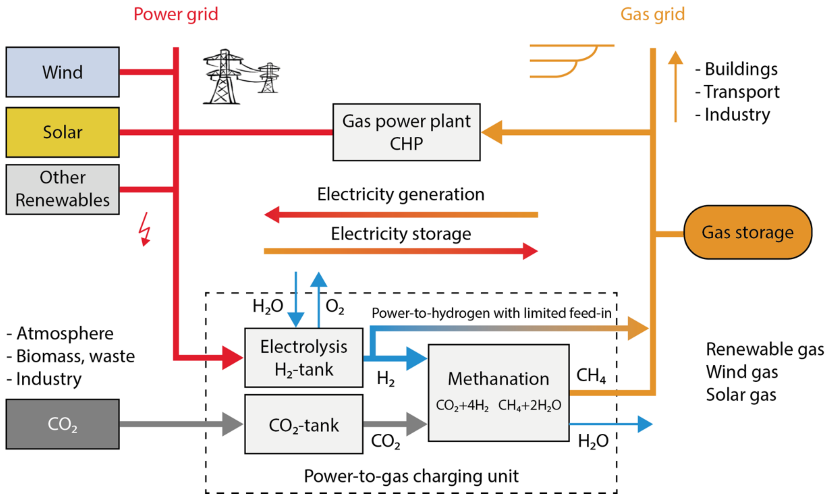
Power-to-Gas (PtG, P2G) describes the conversion of renewable electricity to renewable gas. Two core processes are combined: water electrolysis and CO2 methanation. Renewable electricity drives the water splitting in the electrolysis. The resulting hydrogen is converted with CO2 into methane in the methanation process. Methane is the main constituent of natural gas and thus the generated renewable gas is a substitute natural gas (SNG), that can be fed and stored 1:1 in the natural gas grid.
Power-to-Gas refers to a simple technical replica of the natural photosynthesis process in plants. These plants have developed the process over millions of years to be able to store solar energy over long periods of time. Regardless of its comparatively low efficiency of approximately one percent for solar irradiation to bioenergy, photosynthesis has proven itself in evolution. CO2 and water are converted to compounds containing hydrogen, carbon and oxygen (e.g., C6H12O6) in two steps using solar energy, and oxygen is released into the air.
The first step of photosynthesis, the splitting of water, is mimicked by PtG via electrolysis, with alkaline and membrane electrolysis available today and high-temperature electrolysis being developed. In the second step, H2 reacts with CO2, which is ideally taken from the atmosphere. Two processing options are available today for CO2-methanation: chemical and biological methanation. Biogas or wastewater treatment plants, direct air capture (DAC), geothermal sources, fossil power plants or industrial processes serve as CO2 sources.
The renewable methane gas can be fed into the gas network or stored in connected gas storage sites. From there it can be used for the transport or heat sector or converted back into electricity via gas turbines, CHP, or other devices such as fuel cells (Figure 2). The carbon cycle is closed: the CO2 released to the atmosphere during combustion is the same that was previously extracted from it. A discussion of these CO2 sources and their climate impact is given in Section 4.
3.2. Power-to-Gas: Coupling Electricity and Gas Sectors for Energy Storage
We were able to solve the chicken-and-egg problem of hydrogen by making the gas infrastructure, including transport, storage and applications, accessible for hydrogen via CO2-methanation in Power-to-Gas. Hydrogen has only one-third the energy density of natural gas, dilutes the energy density of the gas accordingly and requires higher compression lines for transport and storage. Methane is easier to compress, store and transport. In addition, hydrogen injection was and is limited to low, single-digit percentages by limitations in gas turbines, gas tanks in vehicles, pore storage and material constraints. Through CO2-methanation, we tapped the entire gas infrastructure for renewable electricity without limitations.
The development of this concept also marked the origin of the term ‘sector coupling’ or ‘sectoral integration’, which refers to energy storage via coupling of electricity and gas sectors. This results in the following opportunities:
- Fluctuating renewable energy can be stored seasonally.
- The existing gas infrastructure can store large TWh-amounts of renewable energy and transport it decoupled in time from the electricity grid all over Europe. This is an opportunity that the electricity infrastructure does not have on this scale.
- By converting the gas back into electricity, Power-to-Gas acts as electricity storage.
- CO2 from biogas plants or other unavoidable sources finds a useful use as a carrier material for hydrogen.
- Process waste heat from all units can be used internally or via heat networks.
- Renewable gas can be generated anywhere and transported, distributed, stored and used without political or geographical constraints.
- Renewable gas can be used for heat supply to couple the electricity and heat sectors.
- Synthetic fuel can be used in mobility to couple the electricity and transport sectors.
3.3. The Chemistry behind Power-to-Gas
Electrolytic water splitting has been known for over 200 years and is therefore not a fundamentally new technology. Nevertheless, it is gaining importance in the context of PtG and PtX and is becoming the core component of chemical energy storage. Water is decomposed into hydrogen and oxygen using electrical energy (see Equation (1)).
Two reversible equilibrium reactions occur in CO2 methanation: the reverse water gas shift reaction and the CO methanation [24,25]. The first chemical reaction is responsible for separating the very weakly reactive CO2 and occurs before the methanation reaction itself (see Equation (3)).
The second chemical reaction is the main reaction in which CO is hydrogenated (see Equation (3)). The CO methanation is as follows:
Thus, the overall reaction for CO2 methanation is Equation (4):
In reverse, this Sabatier reaction is known as steam reforming. This is the standard process for obtaining ‘grey hydrogen’ from fossil gas. The hydration of CO and CO2 is strongly exothermic and volume-reducing, so the principle of Le Chatelier favors the methanation reactions at low temperatures and high pressures. A thermal management that reliably dissipates the released energy is therefore essential to keep the methanation reaction within a favorable temperature range and to shift the reaction equilibrium toward methane. This waste heat can be also used efficiently in other parts of the process, e.g., for the removal of CO2 from biogas or air.
CO2 methanation can be implemented both chemically and biologically in terms of process technology. We compared both in a standardization approach [26]. The biological route uses much lower temperatures and pressures, is more robust and less sensitive to gas impurities of the reactants than the chemical route, but is therefore mainly suitable for decentralized processes, especially in connection with biogas. Chemical methanation has long been proven, requires less space, has higher space-time yields, and is also available at large MW scales and offers a higher waste heat temperature level.
3.4. Novelty of CO2 Methanization and Utilization in Energy Systems
Despite its discovery in France as early as 1902 from Paul Sabatier [27], CO2-methanation was not explored for energy technology until much later, since, analogously to CO methanation, there was no need for it due to the cheap fossil resources available. In the 1970s and 1980s, storing solar energy chemically via CO2 was discussed in terms of the ‘SolChem Concept’ in the USA [28,29]. On a laboratory scale, the first work and plants for CO2 chemical methanation occurred in Japan in the 1990s, as Japan was a resource-poor and densely populated country conducting research on LNG power plants [30,31]. In Germany, CO2 methanation was discussed in the context of fuel cells in the early 2000s [25]. Therefore, by our rethinking of energy systems, the usage of renewable electricity, water plus CO2 as feedstock for renewable fuels, and using the Sabatier process for that particular purpose became popular after we introduced P2G [11,21].
3.5. Combining Electrical, Process and System Engineering Gives Interdisciplinary Solutions
We developed the processing technology that can be used to produce liquid or gaseous hydrocarbons from hydrogen and CO2. To imitate nature, we used compounds of carbon and hydrogen as a storage medium to constantly cover our energy demand with natural sources. The technology was a new phenomenon: we used wind, solar, water and air to generate renewable fuels with the same quality as fossil fuels.
The power supply of an industrialized country such as Germany can therefore be met entirely with renewable energy, despite the natural fluctuations of photovoltaic, wind and hydroelectric power plants. With Power-to-Gas, the storage problem has been technically solved, and we can replace fossil fuels with renewables.
3.6. Terminology: Wind-to-Gas, e-Gas, Power-to-Hydrogen and Power-to-Methane
First, we named the concept ‘wind-to-gas’, then ‘windgas’ and ‘solargas’, to indicate the origin of this renewable gas and distinguish it from fossil natural gas. Similar was the case for ‘renewable power methane’ (RPM) and ‘Renewable Power-to-Methane’ (RPtM) or ‘electric gas’ (e-gas). The most fitting term would have been ‘real natural gas’ (RNG), but instead, inspired by Biomass-to-Liquid (BtL) and Gas-to-Liquid (GtL), we choose ‘Power-to-Gas’ (PtG, P2G).
The term Power-to-Gas became so popular that it was also used for hydrogen starting around 2012. Thus, the terms Power-to-Hydrogen (PtH, P2H) and Power-to-Methane (PtM, P2M) emerged to distinguish both processes. Power-to-Hydrogen describes the classical water electrolysis and the sector coupling via pure hydrogen. Power-to-Methane describes the classical route of Power-to-Gas.
3.7. Efficiencies
Besides the need for a CO2 source, Power-to-Gas concepts differ in efficienciy. A complete Power-to-Gas storage system consists of a transformer, an electrolyzer, an optional methanation unit, compression and gas storage and a discharge technology, which varies according to the sectoral application of the stored gas.
The indicated efficiencies are mean values, from which different overall efficiencies result (Table 1). Regarding Power-to-Hydrogen storage systems, the total efficiency is about 5–12% higher than in the variants with methanation due to the lack of an intermediate methanation step.
3.8. Costs
The production cost of renewable gas and all other green C-based fuels is predominantly driven by investment costs, operating costs of the PtG/PtX-plants and the operation hours per year. Our findings are as follows. The investment costs fell very sharply within a decade and are still falling, as our published database shows (see Table 2). This is because the process plants have so far been manufactured mostly by hand. Investment costs can therefore fall sharply by plant automation and industrial production, similar to photovoltaics [2]. The operating costs are mainly related to renewable electricity, which is becoming cheaper and cheaper, and to taxes, levies and surcharges, which vary greatly and have been the biggest obstacle to the market introduction of PtG over the past decade.
What all chemical plants have in common is that profitability with the high investment costs requires operation at high utilization rates. Three core factors favor the economic operation of PtG/PtX-plants:
- low-cost, renewable electricity;
- high capacity factors/utilization rates;
- favorable regulatory frameworks due to no or low charges, taxes and levies.
3.9. Advantages and Opportunities
Power-to-Gas enables a bidirectional coupling of electricity and gas grids. This is the greatest opportunity: to use the convergence of these systems for a sustainable energy supply with electricity, heat and fuel on the basis of wind and solar electricity using the existing networks and infrastructures for distribution and storage.
In addition to the already existing and huge storage natural gas grid, the great advantage of PtG is the versatile use of methane: unlike pure electricity storage plants such as pumped hydro or batteries, the injected gas does not necessarily have to go back into the power grid at the end but can be used in multiple ways and in multiple places. The stored energy is not fixed locally, as it is the case with pumped hydro or batteries. Seasonal storage can be implemented: the energy collected during sunny and windy seasons can be used in the winter or next spring for completely different purposes and at any location in the natural gas network—for heating, for mobility or even for reverse power generation in one of the many combined heat and power plants. This is not possible with battery or pumped storage: if they had to store the stored energy for a few weeks or even half a year, they would immediately become uneconomical, and some batteries discharge themselves within this time. Additionally, they can only return the power as electricity, and only at the same location.
This does not mean that these storage facilities are worse than Power-to-Gas. In fact, they are twice as efficient if used exclusively as power-to-power storage. However, they are far less flexible and essentially suitable for short-term day-night storage of electricity and for balancing short-term electricity peaks or deficits. Therefore, they do not compete with Power-to-Gas but are an important complement. These different fields of application are shown in Figure 3 based on storage capacities in Germany. Power-to-Gas thus plays a key role in the goal of leveraging synergies by coupling the electricity, heat and mobility sectors, and thus has a special position among storage technologies.
3.10. Disadvantages and Challenges
Power-to-Hydrogen is preferable for reasons of cost and efficiency as long as hydrogen can be stored and used locally, or the blending limit of the gas grid is not reached. If the fossil gas flow rate is low, the injection limit is quickly reached, and hydrogen buffer storage must be used to level the hydrogen injection.
In contrast to methane or natural gas, there are still no mass- and area-wide solutions for some applications. For example, although fuel cells have long been in research and development in heat and transport sectors, a market-ready technology on the required scale is not yet available.
Adapting natural gas infrastructure to higher hydrogen blending involves research and high costs. So far, 2% by volume is permitted in Germany, and 20% is considered technically possible. If all components of a pure hydrogen economy are affordable and available at a sufficient scale, methanation will become obsolete. However, if this is not yet the case, the existing gas infrastructure can be used for renewable gas.
3.11. Dissemination via Energy Economy Studies
In the energy industry, science and ministries, the concept became known through our work at Fraunhofer IEE (formerly ISET) based on simulations in major studies of the long-term scenario ‘Lead Study’ of the Federal Ministry for the Environment (BMU) [32], the German Advisory Council on the Environment (SRU) report [33], the 100% Renewable Electricity Target 2050 of the Federal Environmental Agency (UBA) [34] and the storage study of the Association of German Electrical Engineers (VDE) [35]. We also integrated the concept of P2G and sector coupling in the IPCC special report on renewable energy (SRREN), which made it familiar to the international scientific community [36].
We modeled the entire energy system with new findings in these studies: the existing natural gas grid in Germany is sufficient to buffer electricity surpluses with its large network and underground storage facilities.
For example, the UBA 100% renewable scenario showed a stable electricity supply with no blackouts, where 80% of the electricity demand is covered by wind, solar and hydropower. The remaining 20% of electricity demand were met with pumped hydro, batteries, and Power-to-Gas via gas storage and via CCGT power plants. The results were as follows:
- A full supply with renewable energy in all sectors is technically and ecologically feasible in 2050.
- The technical potential for onshore wind (390 TWh), offshore wind (260 TWh) and photovoltaics (250 TWh) is capable of meeting the energy demand for electricity, heat and individual mobility.
- Despite a very high installation of wind and solar with a total capacity of 225 GW and a peak load in Germany’s power supply of about 80 GW, a reserve power (backup) of about 60 GW is needed; gas power plants based on PtG.
- The security of supply is ensured by PtG storage and gas turbines and CHPs.
- Despite the ideal expansion of the electricity grids and the use of large load management potentials via heat pumps including heat storage (44 TWh), air conditioning (28 TWh) and the controlled charging of electric vehicles (50 TWh), 85 TWh of 150 TWh electricity surpluses remain, which must be integrated via storage.
- The potential of the short-term storage technology pumped hydro is fully utilized with 0.055 TWh. It allows peak shaving but is far from sufficient to cover the storage needs in a 100% renewable power supply.
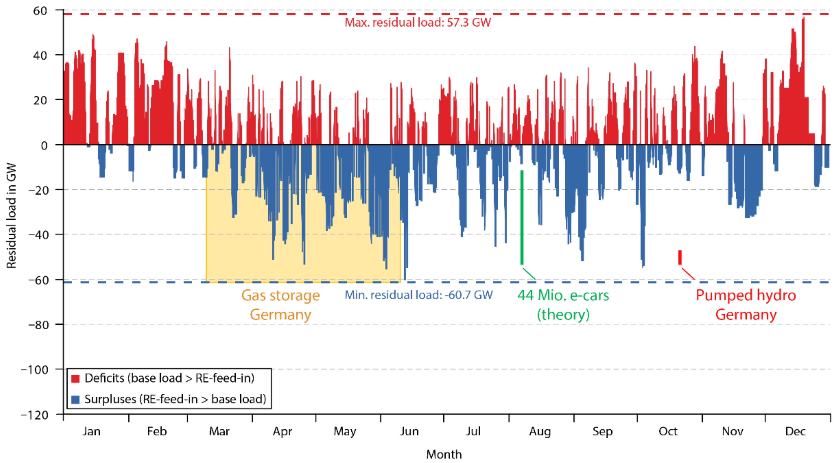
- On the other hand, only 15% of the technical potential of gas storage facilities is required for this task of long-term storage: 75 of 514 TWh. By curtailing 1% of the surplus energy, the PtG capacity of 44 GW can be designed to meet 64% of the maximum surplus capacity. The possible additional one percent of energy storage would involve a disproportionately high technical and financial storage effort.
The existing gas storage potential in Germany is about 220 TWh. With reconversion via CCGT power plants, about 120 TWh of electricity can be generated from the stored gas quantities in purely balance terms, which corresponds to 20% of the annual electricity consumption in Germany. This coud close all gaps in a renewable electricity supply.
In theory, if the 44 million vehicles that exist in Germany today were simultaneously connected to the grid as electric vehicles with a capacity of 20 kWh, half of which can realistically be used to compensate for deficits in the power system, 0.44 TWh of storage capacity would be available. If discharged at 60 GW, all vehicles would be able to stabilize the power grid for 7 h; all gas storage with the same discharge capacity 2000 h, or about 3 months. This comparison shows the storage potential of PtG (Figure 4).
In addition to storage capacities, the gas grid also has a well-developed transport and distribution network. A large continental gas pipeline can transport energy in the form of gas with a capacity of about 70 GW, whereas standard electricity transmission lines have a typical electrical transmission capacity of 3.5 GW (two 380 kV three-phase systems).
Thus, PtG grid coupling not only enables the storage of large amounts of energy, but also a spatial shift in storage and the use of the renewable methane. This is one of the unique selling points of Power-to-Gas.
3.12. Dissemination via Demonstration Plants
The technical feasibility of PtG is demonstrated by numerous pilot plants in Europe and elsewhere. We published the current global status of PtG plants in 2019 [37].
Back in 2009, we decided to implement an initial exploitation of the idea of Power-to-Gas with our partner SolarFuel GmbH. On behalf of this new company, we built at ZSW the first PtG plant. This demonstrated the technical feasibility of the patented PtG technology and provided further insights into CO2 methanation, which was largely unexplored in the energy sector. At Fraunhofer IWES, we explored the energy integration of PtG in accompanying research on optimized plant operation and concepts for high utilization rates of PtG plants at wind parks while simultaneously serving the electricity network operation via forecast balancing.
This alpha plant consists of two containers and uses the air as a CO2 source (Figure 5). The first container contains a scrubber for CO2 absorption in a scrubbing solution and an electrodialysis unit that expels the CO2 from the scrubbing medium. The second container contains a 25 kW alkaline electrolyzer. A chemical fixed-bed reactor in pipes is used for methanation. A fuel maker is used to fuel gas cars with the produced synthetic natural gas (SNG) [38]. As the purpose of this first PtG pilot plant was to demonstrate the technology and concept, no process optimization was carried out, which means that the efficiency of the plant in converting electricity to gas is 40%.
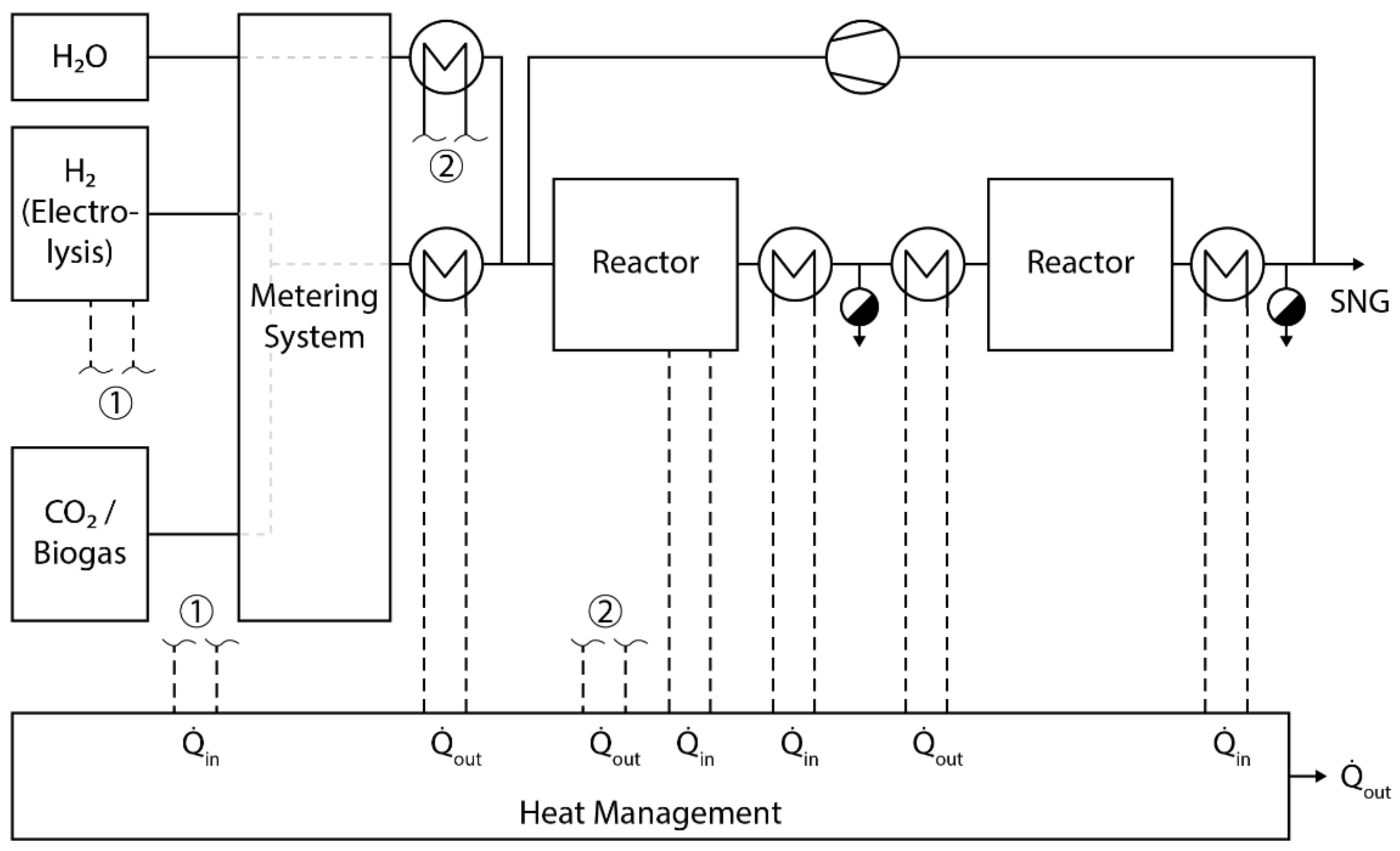
A 250 kW second plant was built for research purposes by the same consortium in Stuttgart with the support of the Federal Ministry of the Environment (Figure 6). Besides upscaling to the MW class, technical and economic research questions have been answered in the integration into the power grid and energy markets such as power balancing, load control, cost-optimized operation and sustainable CO2 sources. A tube and a plate reactor were tested and compared as fixed-bed reactors. The plant supplied 50 m³/h of hydrogen, which was converted into a gas output of 125 kW (LHV) via the two different routes of chemical methanation, corresponding to a product gas flow of 12.5 m³/h [38].
We applied the results to the Audi e-gas plant in Werlte in the world’s first industrial PtG plant. Three alkaline electrolyzers with a total electrical input of 6 MW are used (Figure 7). The hydrogen produced is temporarily stored in a storage tank for up to one hour and compressed to 10 bars for the methanation stage [39]. The tube reactor operates as a fixed-bed reactor at temperatures of 200–350 °C and pressures of 5–10 bar with staged gas addition. Via a single-stage process, a nickel catalyst is used to achieve a methane quality > 90 vol.% CH4. As a CO2 source, biogas from a residual waste plant was used. This connection made it possible to use the waste heat from the electrolyzers and the methanation unit in the upgrading plant to sanitize the residual waste and to separate the CO2 from the amine scrubbing liquid.
Biogas can optionally be used directly as a CH4/CO2 blend in the methanation reactor without upgrading, as the gas cleaning worked well and the reactor catalyst tolerated this [40]. This can be a benefit for future plants, as one gas process unit can be saved. The plant was able to produce up to 1000 t of SNG per year, which can be used to refuel about 1500 Audi g-tron vehicles with an annual mileage of 15,000 km [38].
The project resulted from our first two pilot plants and was implemented by Audi AG together with MAN Diesel & Turbo, EWE AG, MT Biomethan GmbH and us at ZSW and IWES. The accompanying research was funded by the German Federal Ministry for the Environment, and the plant was inaugurated in Lower Saxony in June 2013 [38].
Many other projects in Germany and elsewhere followed. E-On erected a 2 MW P2H pilot plant ‘WindGas’ in Falkenhagen between Hamburg and Berlin. The main reasons for building the plant on the greenfield site were the high level of wind in Brandenburg and its proximity to the gas infrastructure. Back then it was the first plant to feed hydrogen directly into the gas transmission grid in Germany. The alkaline electrolyzers from Hydrogenics produced 360 m3/h of hydrogen. The efficiency (LHV) of the total chain was 66%. It was operated by an E.ON subsidiary (now Uniper), and the gas was marketed to Switzerland via Swissgas AG. We co-initiated the project through feasibility studies in 2010 [41]. Later, a methanation unit was added in the EU project ‘Store and go’. Other projects such as the hydrogen energy park in Mainz from Siemens AG, Linde AG and Stadtwerke Mainz AG with a newly developed 6 MW new proton exchange membrane electrolysis followed later in the same way.
Additionally, in 2013, Thüga AG, as a municipal utility consortium with 12 project partners, built the first P2H plant in Frankfurt for the gas distribution network. Here, ITM Power’s 315 kW PEM electrolysis produced 60–70 m3/h of 99.8 vol-% pure hydrogen from 4.9–5.2 kWh electricity per cubic meter. This hydrogen flow was mixed with a fossil gas flow of 3000 m3/h in the gas network via a gas pressure control measurement and mixing system. The gas flow in the distribution network in the inner city of Frankfurt is constant over the year, allowing a low-dose injection of green hydrogen [39].
Enertrag’s hybrid power plant in Prenzlau consists of a self-built 600 kW alkaline electrolysis plant, a hydrogen storage facility, a biogas plant, and a CHP unit. The 120 m3/h hydrogens are directly marketed via trailers for transport and industry. The plant was inaugurated in 2011 and entered the test phase. It has been in operation since 2013, and since 2014, inspired by us, the hydrogen has been fed into the natural gas grid to be supplied to approximately 8000 customers of Greenpeace Energy eG. With the proWindgas gas tariff, they are the first energy supplier to promote PtG via direct marketing to customers to promote the energy transition towards a 100% renewable energy supply [41,42].
Our pilot projects and these other early-stage projects can be used as blueprints for future commercial plants.
3.13. From Power-to-Gas to Sector Coupling to Power-to-X–Definitions
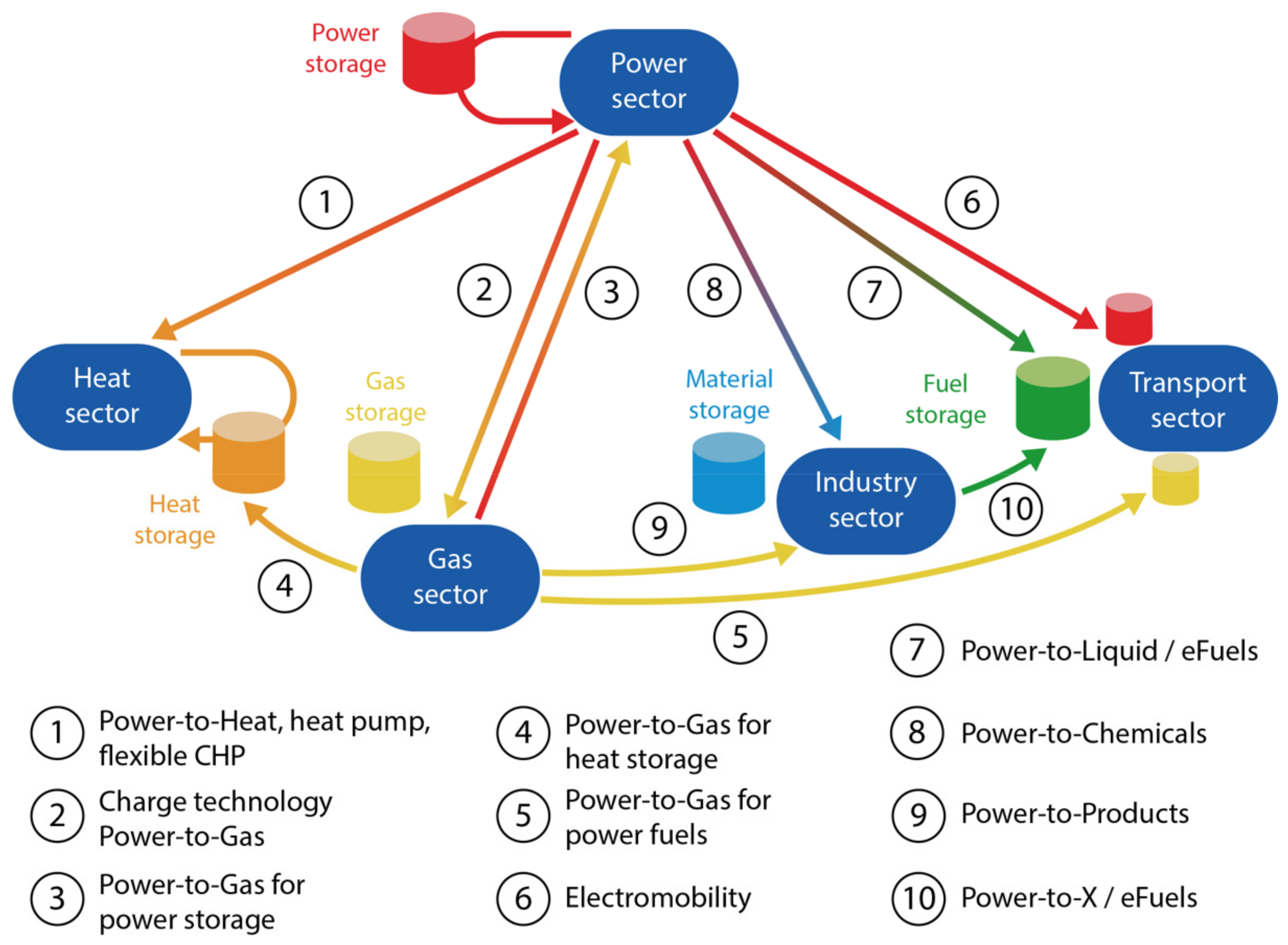
Power-to-Gas is the cornerstone of sector coupling and sectoral integration:
- Electricity and gas sectors are coupled for seasonal energy storage;
- Electricity and heat sectors are linked via renewable gas;
- Electricity and transport sectors are coupled via synthetic fuel;
- Renewable gas serves as a link between the power and industrial sectors to make steel, chemicals and other sectors that are difficult to decarbonize climate-neutral (see Figure 8).
All at the same time, Power-to-Gas is used where pure electricity applications are not technically sufficient to make the respective sector completely climate-neutral.
We inspired so many other researchers, who came up with similar ideas by using renewable electricity as ‘primary energy’, that we decided in 2013/14 to summarize all terms to one: Power-to-X. We gave two new definitions, which became very popular over time:
Definition of Power fuels/eFuels: Power fuels or eFuels are chemical energy carriers based on electrical energy, produced via the electrolysis of water and an optional synthesis (PtG, PtL) and used in mobility. Examples are hydrogen, SNG, methanol, ammonia and Fischer–Tropsch fuels like e-diesel or e-kerosene [41].
Definition of Power-to-X: Power-to-X describes the conversion and storage of electrical energy into an energy carrier (gas, fuel or raw material) or a product (basic material, feedstock). It is a collective term for Power-to-Gas, Power-to-Liquid, Power-to-Fuel, Power-to-Chemicals and Power-to-Product [3,43].
This completed the existing definitions of PtG, PtL, PtC, eFuel and sector coupling [41]:
Definition of Power-to-Gas: A Power-to-Gas (PtG) plant describes a facility for converting electrical energy into a gaseous energy carrier such as hydrogen or methane via water electrolysis and optional methanation and storing it. It is thus part of an energy storage system. Power-to-Gas describes on the one hand the plant for conversion and storage and on the other hand also the overall system, which consists of injection (electrolysis, methanation) storage (gas storage, gas grid) and withdrawal (gas power plants, CHP, gas mobility and gas heating).
Definition of Power-to-Liquid: A Power-to-Liquid (PtL) plant describes a plant for the conversion and storage of electrical energy into a liquid energy carrier such as kerosene, diesel or methanol via water electrolysis and syntheses. The energy carrier is used for energy.
Definition of Power-to-Chemicals: A Power-to-Chemicals (PtC) plant describes a plant for converting and storing electrical energy into a chemical product such as methanol via water electrolysis and syntheses. The product is used as a material.
Definition of eFuel: An eFuel is a liquid or gaseous fuel based on the conversion and storage of electrical energy via electrolysis and optional syntheses (Power-to-X). The energy carrier is used for energy.
Definition of sector coupling: Sector coupling describes the coupling of the electricity sector with the building, transport and industry sectors via, for example, CHP, heat pumps, heating rods, electromobility, Power-to-X using energy conversion, energy networks (gas, fuel, raw material, electricity) and energy storage.
4. Discussion of Electricity- and C-Sources for the Generation of C-Based Fuels
4.1. Climate-Neutrality of CO2 Based Fuels and Their Usage
The use of CO2 in the process is climate-neutral overall unless fossil CO2 is released specifically for this purpose. Fossil power generation does not become CO2-neutral by the utilization of the produced CO2, since the CO2 is released back into the atmosphere after use (CCU—carbon capture and usage) in the PtG storage cycle. In addition, CO2-rich gases such as those from biogas or biomass are more suitable as a source than flue gas from power plants, since the energy required to capture the CO2 is lower [21].
4.2. From Fossil CO2 to Direct Air Capture—C-Sources for C-Based Fuels
After biogas upgrading, pure CO2 is available, which is cost-efficient and climate-neutral since it is normally unused and was removed from the atmosphere by plants within a very short period of time.
Another option for using biogenic CO2 is the use of raw biogas, which is advantageous because the CO2 does not have to be extracted separately. Hydrogen reacts with the CO2 content of biogas directly in the methanation reactor. This enables a very broad and distributed use of the decentral renewable energy source via the central gas infrastructure, as opposed to rigid on-site electricity generation from biogas as a base load.
The obvious option is to use CO2 directly from the air, which together with a CCS process would lead to a reduction in the CO2 content of the air. Our first 25 kW P2G pilot plant uses separation from air via absorption in caustic liquids [22]. However, capture from the air is only possible with high technical and financial effort, which is why this option has not been explored fully. The advantage is site independence for CO2 recovery, which is often a limiting or site-determining factor in the implementation of hydrogenation syntheses.
Large quantities of CO2 are produced in power plants and industrial facilities. While fossil power plants can be replaced by renewable energies, for example, cement industries continue to inevitably emit CO2. The same applies to other processes that are independent of the energy transition. However, unlike biogenic or atmospheric CO2, these CO2 sources are not distributed decentrally, which is an advantage for large-scale production of synthetic fuel such as ‘e-kerosene’. Combining near-shore offshore wind farms, which generate constant and cheap electricity, with large CO2 emitters such as cement plants results in the synergetic approach of generating ‘unavoidable’ jet fuel from ‘unavoidable’ CO2 emissions.
Coal power plants are not considered a source of CO2, since in the short term, CCU with PtX is not intended to ‘green-wash’ CO2-intensive power generation and in the long run, fossil power plants will disappear during the energy transition and along with them the CO2 sources. Furthermore, the additional effort of flue gas treatment increases the primary energy consumption of power plants by 20–44% [44]. This means that part of the CO2 emissions that are captured are caused by the increased energy input just because CO2 is to be captured. On closer examination, this is paradoxical and only has a net effect if the CO2 is stored for thousands of years or no longer escapes into the atmosphere when firmly bound via material use.
CO2 recycling is understood to be a closed CO2 cycle. After the combustion of renewable methane, CO2 is separated from the flue gases and made available again for methanation. If pure oxygen, which is a by-product of electrolysis, is used in the combustion of the methane and burned under the correct stoichiometric ratio, CO2 capture is possible without much effort, since only CO2 and water are produced in such combustion.
4.3. Sustainable, Renewable C-Based Fuels Require Renewable Electricity and Proper Frameworks
In addition to the CO2 source, the use of renewable electricity is the basic prerequisite for a reduction of CO2 by Power-to-Gas: the CO2 intensity of the electricity source determines the CO2 intensity of the PtX product or hydrogen derivate. Choosing fossil electricity as an energy source for PtX reverses its climate effect: converting lignite into electricity into gas, and thus a fossil chemical energy carrier into an electrical one, and in the second step again back into a chemical one, we do not get a CO2-neutral energy carrier. The PtG gas would emit about 3200 g CO2 eq./kWh and thus more than eight times more as fossil electricity from fossil gas when converted back into electricity [3].
From the perspective of sustainability, the use of renewable electricity is a must, and biogenic or atmospheric CO2 sources are favored. The challenge and future main research question remain how to modify the regulatory framework in that way that renewable gas becomes competitive against natural gas [45]. CO2 pricing, quota systems and OPEX funding are initial approaches towards the broad market introduction of PtX.
5. Conclusions
We created and patented a new storage concept called Power-to-Gas at the end of the 2000s that imitates photosynthesis and generates renewable hydrocarbons from renewable electricity, water and CO2. This inspired others and led to the concepts of synthetic fuels (eFuels, Power-to-Liquids and Power-to-Chemicals). We summarized all power-to- concepts in the term Power-to-X in 2013. We built the first demo plants at a kW-scale, which led to the first MW-scale plants at the beginning of the 2010s and inspired many other PtX-plants worldwide.
The main advantages of PtG are that we (i) solved the chicken-egg-problem of H2, (ii) solved the seasonal storage problem of wind and solar by coupling electricity and gas sectors and thus using existing infrastructures with TWh-scale storage for renewables and (iii) created a way to generate eFuels from wind and solar for transport, industry and buildings.
The main disadvantages are the need for a CO2 source and the lower efficiency compared to the direct use of electricity or hydrogen. However, this is very useful for all applications that cannot decarbonize or otherwise become climate-neutral: long-distance transport like ship, airplanes and heavy-duty, 100% renewable electricity supply and many industry applications such as high-temperature processes.
6. Patents
We patented our Power-to-Gas concept innovation in the EU and USA:
- Specht, M.; Sterner, M.; Stürmer, B.; Frick, V.; Hahn, B. Renewable Power Methane–Stromspeicherung durch Kopplung von Strom- und Gasnetz–Wind/PV-to-SNG. DE 10 2009 018 126.1, 9 April 2009.
- Specht, M.; Sterner, M.; Stürmer, B.; Frick, V.; Hahn, B. Energy System and Supply Method, EP 00 0002 3345 90B1, 9 April 2010.
- Specht, M.; Sterner, M.; Stürmer, B.; Frick, V.; Hahn, B. Energy System and Supply Method, US 00 0009 0571 38B2, 9 April 2010.
Author Contributions
Conceptualization, formal analysis, investigation, resources, data curation, visualization, project administration, funding acquisition, M.S. (Michael Sterner) and M.S. (Michael Specht); methodology, software, writing—original draft preparation, M.S. (Michael Sterner); validation, writing—review and editing, supervision, M.S. (Michael Specht). All authors have read and agreed to the published version of the manuscript.
Funding
This research was partly funded by the German Federal Environmental Agency in the research project ‘Modeling of 100 percent renewable power generation in 2050′, FKZ 363 01 277. The assembly and operation of the 25-kW P2G ® plant were financed by SolarFuel GmbH, renamed ETOGAS GmbH in 2013. The assembly and operation of the 250 kW P2G ® plant were supported by the Federal Ministry for Economic Affairs and Energy based on a resolution of the German Parliament (funded project no.: 0325275). The construction of the 6000 kW e-gas plant is an investment of the automobile manufacturer Audi AG. The monitoring of the e-gas plant is supported by the Federal Ministry for Economic Affairs and Energy based on a resolution of the German Parliament (funded project no.: 0325428).
Acknowledgments
We thank Franz Bauer, OTH Regensburg, for his technical support in drawing the figures and illustrations for this publication.
Conflicts of Interest
The authors declare no conflict of interest.
References
- IEA. World Energy Outlook; OECD: Paris, France, 2020. [Google Scholar]
- Kost, C.; Shammugam, S.; Fluri, V.; Peper, D.; Memar, A.; Schlegl, T. Levelized Cost of Electricity-Renewable Energy Technologies. Fraunhofer Inst. Sol. Energy Syst. ISE 2021, 144, 2–5. [Google Scholar]
- Sterner, M.; Stadler, I. Handbook of Energy Storage: Demand, Technologies, Integration; Springer: Berlin/Heidelberg, Germany, 2018; ISBN 978-3-662-55503-3. [Google Scholar]
- Sauer, D. The demand for energy storage in regenerative energy systems. In Proceedings of the First International Renewable Energy Storage Conference (Eurosolar IRES I), Gelsenkirchen, Germany, 30 October 2006. [Google Scholar]
- VDE. Energiespeicher in Stromversorgungssystemen mit Hohem Anteil Erneuerbarer Energieträger; VDE (Verband der Elektrotechnik, Elektronik und Informationstechnik): Frankfurt, Germany, 2009. [Google Scholar]
- Enßlin, C.; Füller, G.; Hahn, B.; Hoppe-Kilpper, M.; Rohrig, K. The Scientific Measurement and Evaluation Programme in the German 250 MW Wind Programme. In Proceedings of the European Wind Energy Conference, Kassel, Germany, 8–12 March 1993. [Google Scholar]
- Ernst, B. Entwicklung eines Windleistungsprognosemodells zur Verbesserung der Kraftwerkseinsatzplanung. Ph.D. Thesis, University of Kassel, Kassel, Germany, 2003. [Google Scholar]
- Mackensen, R.; Rohrig, K.; Emanuel, H.; Saint-Drenan, Y.; Schlögl, F. Das regenerative Kombikraftwerk: Abschlussbericht, Kassel. 2008. Available online: https://www.researchgate.net/profile/Kurt-Rohrig/publication/46112051_Das_regenerative_Kombikraftwerk/links/0deec517c0f740311b000000/Das-regenerative-Kombikraftwerk.pdf (accessed on 2 August 2021).
- Mackensen, R. Herausforderungen und Lösungen für eine regenerative Elektrizitätsversorgung Deutschlands. Ph.D. Thesis, University of Kassel, Kassel, Germany, 2011. [Google Scholar]
- WBGU. World in Transition—Future Bioenergy and Sustainable Land Use: Flagship Report 2008; WBGU: Berlin, Germany, 2009. [Google Scholar]
- Bandi, A.; Specht, M.; Weimer, T.; Schaber, K. CO2 recycling for hydrogen storage and transportation: Electrochemical CO2 removal and fixation. Energy Convers. Manag. 1995, 36, 899. [Google Scholar] [CrossRef]
- Specht, M.; Staiss, F.; Bandi, A.; Weimer, T. Comparison of the renewable transportation fuels, liquid hydrogen and methanol, with gasoline—energetic and economic aspects. Energy Convers. Manag. 1998, 23, 387–396. [Google Scholar] [CrossRef]
- Specht, M.; Bandi, A.; Elser, M.; Heberle, A.; Maier, C.U.; Schaber, K.; Weimer, T. CO2-Recycling zur Herstellung von Methanol: Endbericht, Stuttgart. 2000. Available online: https://www.sfv.de/pdf/Report_000700_ZSW_CO2_to_MeOH_LQ2.pdf (accessed on 2 August 2021).
- Weimer, T.; Schaber, K.; Specht, M.; Bandi, A. Methanol from atmospheric carbon dioxide: A liquid zero emission fuel for the future. Energy Convers. Manag. 1996, 37, 1351–1356. [Google Scholar] [CrossRef]
- Specht, M.; Zuberbühler, U.; Koppatz, S.; Pfeifer, C.; Marquard-Möllenstedt, T. Transfer of Absorption Enhanced Reforming Process (AER) from Pilot Scale to an 8 MW Gasification Plant in Guessing, Austria. In Proceedings of the 16th European Biomass Conference & Exhibition’ of EUBIA, Feria Valencia, Spain, 2–6 June 2008; p. 20. [Google Scholar]
- FAO. The State of Food and Agriculture 2008: Biofuels—Prospects, Risks and Opportunities; FAO: Rome, Italy, 2008; ISBN 9251059802. [Google Scholar]
- Sachs, J.D. Surging food prices mean global instability: Misguided policies favor biofuels over grain for hungry people. Sci. Am. Mag. 2008, 2. Available online: https://www.scientificamerican.com/article/surging-food-prices/ (accessed on 2 August 2021).
- Schmid, J.; Sterner, M. Bioenergy in future energy systems. In Proceedings of the 16th European Biomass Conference & Exhibition’ of EUBIA, Feria Valencia, Spain, 2–6 June 2008; p. 26. [Google Scholar]
- Sterner, M.; Schmid, J. Electromobility—An efficient alternative to conventional biofuels to put biomass on the road. In Proceedings of the 16th European Biomass Conference & Exhibition’ of EUBIA, Feria Valencia, Spain, 2–6 June 2008; p. 16. [Google Scholar]
- Specht, M.; Sterner, M.; Stuermer, B.; Frick, V.; Hahn, B. Energieversorgungssystem und Betriebsverfahren. Germany Patent 10 2009 018 126.1, 9 April 2009. [Google Scholar]
- Sterner, M. Bioenergy and Renewable Power Methane in Integrated 100% Renewable Energy Systems: Limiting Global Warming by Transforming Energy Systems. Ph.D. Thesis, University of Kassel, Kassel, Germany, 2009. [Google Scholar]
- Specht, M.; Sterner, M.; Brellochs, J.; Frick, V.; Stuermer, B.; Zuberbühler, U.; Waldstein, G. Speicherung von Bioenergie und erneuerbarem Strom im Erdgasnetz: Storage of Renewable Energy in the Natural Gas Grid. Erdöl Erdgas Kohle 2010, 126, 342–346. [Google Scholar]
- Sterner, M.; Jentsch, M.; Holzhammer, U. Energiewirtschaftliche und Ökologische Bewertung eines Windgas-Angebotes; Gutachten: Hamburg, Kassel, 2011. [Google Scholar] [CrossRef]
- Kopyscinski, J.; Schildhauer, T.J.; Biollaz, S.M. Production of synthetic natural gas (SNG) from coal and dry biomass—A technology review from 1950 to 2009. Fuel 2010, 89, 1763–1783. [Google Scholar] [CrossRef]
- Schulz, A. Selektive Methanisierung von CO in Anwesenheit von CO2 zur Reinigung von Wasserstoff unter den Bedingungen einer PEM-Brennstoffzelle. Ph.D. Thesis, University of Karlsruhe, Karlsruhe, Germany, 2005. [Google Scholar]
- Thema, M.; Weidlich, T.; Hörl, M.; Bellack, A.; Mörs, F.; Hackl, F.; Kohlmayer, M.; Gleich, J.; Stabenau, C.; Trabold, T.; et al. Biological CO2-Methanation: An Approach to Standardization. Energies 2019, 12, 1670. [Google Scholar] [CrossRef] [Green Version]
- Sabatier, P.; Senderens, J.-B. Nouvelles syntheses du methane: New method for the synthesis of methane. J. Chem. Soc. 1902, 82, 333. [Google Scholar]
- Chubb, T.A.; Nemecek, J.J.; Simmons, D.E. Application of chemical engineering to large scale solar energy. Sol. Energy 1978, 20, 219–224. [Google Scholar] [CrossRef]
- McCrary, J.H.; McCrary, G.E.; Chubb, T.A.; Nemecek, J.J.; Simmons, D.E. An experimental study of the CO2 x CH4 reforming-methanation cycle as a mechanism for converting and transporting solar energy. Sol. Energy 1982, 29, 141–151. [Google Scholar] [CrossRef]
- Hasegawa, N.; Yoshida, T.; Tsuji, M.; Tamaura, Y. Integrated carbon recycling system for mitigation of CO2 emissions utilizing degraded thermal energy. Energy Convers. Manag. 1996, 37, 1333–1338. [Google Scholar] [CrossRef]
- Yoshida, T.; Tsuji, M.; Tamaura, Y.; Hurue, T.; Hayashida, T.; Ogawa, K. Carbon recycling system through methanation of CO2 in flue gas in LNG power plant. Energy Convers. Manag. 1997, 38, S443–S448. [Google Scholar] [CrossRef]
- Nitsch, J.; Pregger, T.; Sterner, M.; Wenzel, B. Langfristszenarien und Strategien für den Ausbau der Erneuerbaren Energien in Deutschland bei Berücksichtigung der Entwicklung in Europa und Global: Schlussbericht BMU–FKZ 03MAP146, Berlin. 2012. Available online: http://www.erneuerbare-energien.de/files/pdfs/allgemein/application/pdf/leitstudie2011_bf.pdf (accessed on 2 August 2021).
- SRU. Wege zur 100% Erneuerbaren Stromversorgung: Sondergutachten; Erich Schmidt: Berlin, Germany, 2011; ISBN 978-3-503-13606-3. [Google Scholar]
- UBA. 2050: 100% Erneuerbarer Strom: Energieziel 2050; Umweltbundesamt: Dessau-Roßlau, Germany, 2010. [Google Scholar]
- VDE ETG. Energiespeicher für die Energiewende, Frankfurt am Main. 2012. Available online: https://shop.vde.com/de/vde-studie-energiespeicher-für-die-energiewende-6 (accessed on 2 August 2021).
- Edenhofer, O.; Pichs Madruga, R.; Sokona, Y. Renewable Energy Sources and Climate Change Mitigation: Special Report of the Intergovernmental Panel on Climate Change; Cambridge University Press: New York, NY, USA, 2012; ISBN 1107607108. [Google Scholar]
- Thema, M.; Bauer, F.; Sterner, M. Power-to-Gas: Electrolysis and methanation status review. Renew. Sustain. Energy Rev. 2019, 112, 775–787. [Google Scholar] [CrossRef]
- Specht, M.; Brellochs, J.; Frick, V.; Stürmer, B.; Zuberbühler, U. Technical Realization of Power-to-Gas Technology (P2G®): Production of Substitute Natural Gas by Catalytic Methanation of H2/CO2. In Natural Gas and Renewable Methane for Powertrains: Future Strategies for a Climate-Neutral Mobility, 1st ed.; van Basshuysen, R., Ed.; Springer: Berlin/Heidelberg, Germany, 2016; pp. 141–224. ISBN 978-3319232249. [Google Scholar]
- Estermann, T. Entwicklung eines Konzeptes zur Erweiterung der Thüga-Power-to-Gas-Demonstrationsanlage um eine Methanisierungseinheit: Development of a Concept to Expand the Power-to-Gas Demonstration Plant of the Thüga Group about a Methanation Unit. Bachelorarbeit; OTH Regensburg: Regensburg, Germany, 2014. [Google Scholar]
- Hentschel, J. Potenziale nachhaltiger Power-to-Gas Kraftstoffe aus Elektrizitätsüberschüssen im Jahr 2030. Ph.D. Thesis, Technical University of Berlin, Berlin, Germany, 2014. [Google Scholar]
- Sterner, M.; Stadler, I. Energiespeicher: Bedarf, Technologien, Integration; Springer Vieweg: Berlin/Heidelberg, Germany, 2014; ISBN 978-3-642-37379-4. [Google Scholar]
- Greenpeace Energy, eG. Rückenwind für die Energiewende: Der Gastarif Prowindgas. Available online: http://www.windgas.de (accessed on 2 August 2021).
- Sterner, M.; Moser, A.; Thema, M.; Eckert, F.; Schäfer, A.; Drees, T.; Rehtanz, C.; Häger, U.; Kays, J.; Seack, A.; et al. Stromspeicher in der Energiewende: Untersuchung zum Bedarf an neuen Stromspeichern in Deutschland für den Erzeugungsausgleich, Systemdienstleistungen und im Verteilnetz; Agora-Speicherstudie 050/10-S-2014/DE: Berlin, Germany, 2014. [Google Scholar] [CrossRef]
- Trost, T.; Horn, S.; Jentsch, M.; Sterner, M. Erneuerbares Methan: Analyse der CO2-Potenziale für Power-to-Gas Anlagen in Deutschland. Z Energ. 2012, 36, 173–190. [Google Scholar] [CrossRef]
- Jentsch, M. Potenziale von Power-to-Gas Energiespeichern: Modellbasierte Analyse des markt- und Netzseitigen Einsatzes im Zukünftigen Stromversorgungssystem. Ph.D. Thesis, University of Kassel, Kassel, Germany, 2014. [Google Scholar]
Figure 1.
First approach to couple power and gas infrastructure via electrolysis; first published in our bioenergy flagship report at the German Advisory Council on Global Change (WGBU) [10].
Figure 1.
First approach to couple power and gas infrastructure via electrolysis; first published in our bioenergy flagship report at the German Advisory Council on Global Change (WGBU) [10].

Figure 2.
Basic concept of Power-to-Gas from 2008, first published in 2009 [20].
Figure 2.
Basic concept of Power-to-Gas from 2008, first published in 2009 [20].

Figure 3.
Storage capacities and duration of discharge of various storage technologies [3].
Figure 3.
Storage capacities and duration of discharge of various storage technologies [3].

Figure 4.
Deficits and surpluses in a 100% renewable electricity supply over the year 2050 in an example scenario for Germany and possible electricity storage options [3].
Figure 4.
Deficits and surpluses in a 100% renewable electricity supply over the year 2050 in an example scenario for Germany and possible electricity storage options [3].

Figure 5.
Block diagram of the first 25 kW PtG pilot plant at ZSW Stuttgart [38].
Figure 5.
Block diagram of the first 25 kW PtG pilot plant at ZSW Stuttgart [38].

Figure 6.
Block diagram of the second 250 kW PtG pilot plant at ZSW Stuttgart [38].
Figure 6.
Block diagram of the second 250 kW PtG pilot plant at ZSW Stuttgart [38].

Figure 7.
Block diagram of the resulting first commercial 6000 kW PtG plant at Audi AG [38].
Figure 7.
Block diagram of the resulting first commercial 6000 kW PtG plant at Audi AG [38].

Figure 8.
Sector coupling resulted from Power-to-Gas and Power-to-X. It links the sectors of electricity, heat, transport and industry via energy storage and energy converters and using renewable electricity as ‘primary energy’ for ecarbonization [3].
Figure 8.
Sector coupling resulted from Power-to-Gas and Power-to-X. It links the sectors of electricity, heat, transport and industry via energy storage and energy converters and using renewable electricity as ‘primary energy’ for ecarbonization [3].


Table 1.
Efficiency chains (LHV) for different P2G applications, based on standard industry electrolysis technologies (alkaline and membrane (PEM)) and chemical methanation without energy demand for CO2 provision and balance of plant. * compression to 80 bars [3,23].
| Pathway | Overall Efficiency | Boundary Condition |
|---|---|---|
| Power-to-Hydrogen | 54–72% | Compression to 200 bars (gas storage) |
| 57–73% | Compression to 80 bars (gas grid) | |
| 64–77% | Without compression | |
| Power-to-Methane | 49–64% | Compression to 200 bars (gas storage) |
| 50–64% | Compression to 80 bars (gas grid) | |
| 51–65% | Without compression | |
| P2H-to-Power | 34–44% | Power generation via fuel cell (60%) * or |
| P2M-to-Power | 30–38% | combined-cycle power plant (60%) * |
| P2M-to-Heat and Power | 43–54% | CHP (45% heat and 40% electricity) * |
| P2M-to-Heat | 53–82% | Condensing boiler (105%) * |
| P2H-to-EnginePower | 34–44% | Conversion in fuel cell (60%) * |
| P2M-to-EnginePower | 18–22% | Combustion in gas engine (35%) * |
Table 2.
Average investment costs for the core components of PtG: alkaline and membrane electrolysis (alkaline, membrane (PEM)) and methanation (chemical, biological) for the MW class. The kW unit refers to the electrical power input of the electrolysis, not the gas flow rate [3].
Table 2.
Average investment costs for the core components of PtG: alkaline and membrane electrolysis (alkaline, membrane (PEM)) and methanation (chemical, biological) for the MW class. The kW unit refers to the electrical power input of the electrolysis, not the gas flow rate [3].
| Year | Alkaline Electrolysis in EUR/kW | Membrane Electrolysis in EUR/kW | Chemical Methanation in EUR/kW | Biological Methanation in EUR/kW |
|---|---|---|---|---|
| 2010 | 1150 | 1650 | 1040 | 1600 |
| 2015 | 980 | 1350 | 870 | 1300 |
| 2020 | 850 | 1130 | 740 | 1050 |
| 2025 | 720 | 950 | 620 | 860 |
| 2030 | 620 | 780 | 520 | 690 |
| 2040 | 460 | 530 | 370 | 460 |
| 2050 | 330 | 350 | 260 | 300 |
Publisher’s Note: MDPI stays neutral with regard to jurisdictional claims in published maps and institutional affiliations. |
© 2021 by the authors. Licensee MDPI, Basel, Switzerland. This article is an open access article distributed under the terms and conditions of the Creative Commons Attribution (CC BY) license (https://creativecommons.org/licenses/by/4.0/).
Share and Cite
MDPI and ACS Style
Sterner, M.; Specht, M. Power-to-Gas and Power-to-X—The History and Results of Developing a New Storage Concept. Energies 2021, 14, 6594. https://0-doi-org.brum.beds.ac.uk/10.3390/en14206594
AMA Style
Sterner M, Specht M. Power-to-Gas and Power-to-X—The History and Results of Developing a New Storage Concept. Energies. 2021; 14(20):6594. https://0-doi-org.brum.beds.ac.uk/10.3390/en14206594
Chicago/Turabian StyleSterner, Michael, and Michael Specht. 2021. "Power-to-Gas and Power-to-X—The History and Results of Developing a New Storage Concept" Energies 14, no. 20: 6594. https://0-doi-org.brum.beds.ac.uk/10.3390/en14206594
Note that from the first issue of 2016, this journal uses article numbers instead of page numbers. See further details here.