
Co-Gasification Characteristics of Coal and Biomass Using CO2 Reactant under Thermodynamic Equilibrium Modelling


1
Department of Chemical Engineering, Monash University, Wellington Rd, Clayton 3800, Australia
2
Department of Mechanical Engineering and Product Design Engineering, Swinburne University of Technology, Hawthorn 3122, Australia
*
Author to whom correspondence should be addressed.
Energies 2021, 14(21), 7384; https://0-doi-org.brum.beds.ac.uk/10.3390/en14217384
Submission received: 11 September 2021
/
Revised: 15 October 2021
/
Accepted: 1 November 2021
/
Published: 5 November 2021
(This article belongs to the Special Issue Recent Development in Hydrogen Energy: Production, Storage, and Techno-Economic Analysis)
Abstract
:This study assessed the entrained flow co-gasification characteristics of coal and biomass using thermodynamic equilibrium modelling. The model was validated against entrained flow gasifier data published in the literature. The gasification performance was evaluated under different operating conditions, such as equivalence ratio, temperature, pressure and coal to biomass ratio. It is observed that the lower heating value (LHV) and cold gas efficiency (CGE) increase with increasing temperature until the process reaches a steady state. The effect of pressure on syngas composition is dominant only at non-steady state conditions (<1100 °C). The variation in syngas composition is minor up to the blending of 50% biomass (PB50). However, the PB50 shows a higher LHV and CGE than pure coal by 12%and 18%, respectively. Overall, biomass blending of up to 50% favours gasification performance with an LHV of 12 MJ/kg and a CGE of 78%.
1. Introduction
Since the industrial revolution in 1750, CO2 in the atmosphere has increased by 45%, resulting in climate change and global warming [1]. The main contributor to CO2 emission is power generation, accounting for 39.7%, followed by industry, transport, building and others with 25%, 21.2%, 8.5% and 5.6%, respectively [2]. As the second-largest source of power generation, coal emits 41% of total CO2 worldwide [2]. Hence, various technologies have been employed to reduce, capture and utilise CO2 from power generation. One such technique is integrated gasification combined cycle (IGCC) power generation with carbon capture and storage (CCS) [3].
The gasification produces syngas (CO, H2, CH4 and CO2, etc.) by partial oxidation of carbonaceous solid fuels such as coal and biomass [4]. The syngas generated from gasification is used for power generation using gas turbines and chemical synthesis with appropriate downstream treatment [5]. CO2 generated from gasification plants can be reused in the same cycle as a reactant, which helps cut costly oxygen-enriched air, oxygen and steam [6]. Thus, besides environmental benefits, the cost of producing steam and oxygen from air separation units can be reduced substantially [7]. Furthermore, the recycling of CO2 offers a wide range of CO/H2 production, which is the precursor for a wide range of chemicals [8].
Numerous studies on coal and biomass gasification have been conducted using CO2 as a reactant [9,10,11,12,13,14,15]. The objectives of those investigations were kinetic studies [13,16], gas composition and subsequent char/ash characterisation [10,17] and fluid dynamic and process modelling [18,19,20]. The kinetic parameters are useful for understanding the reactivity of the fuels, which helps set the operating conditions for pilot scale analysis. Besides, the kinetic parameters are also important for fluid dynamics and process modelling studies [13]. The pilot-scale studies are crucial to assess the performance characteristics of the gasifier and operating conditions [21]. The process modelling is particularly vital, capable of providing a wide range of data while eliminating the need for time and costly experimental campaigns [22].
Shahabuddin et al. [22] studied the gasification characteristics of bituminous coal using a process modelling approach under different reactants, such as oxygen, steam, CO2 and a mixture of those. Results showed that the combination of steam and oxygen performs better compared to other reactants. The steam–oxygen reactant showed the highest H2/CO ratio of 0.74, while the ratio was about 0.32 using steam–CO2 and pure oxygen. Sadhwani et al. [18] studied Aspen plus process modelling for the gasification of biomass using CO2 reactant with known kinetics. The results were validated with experimental data and found a co-efficient of determination between 84.38% and 98.72% for gas compositions under different operating conditions. The co-gasification of coal and biomass is gaining popularity due to its favourable impact on carbon conversion, gas quality and emission, thus making the system more environmentally benign [23,24]. Ali et al. [25] studied entrained flow co-gasification of different coals and rice straw biomass using Aspen plus process modelling. Among the different blending ratios tested, a 10% addition of biomass showed the best gasification performance with a CGE of 78.5%.
Similarly, Kuo and Wu [26] studied the co-gasification characteristics of coal and biomass using Aspen plus thermodynamic equilibrium modelling under steam gasification conditions along with a certain percentage of CO2. Results showed that the addition of CO2 improves energy conversion and exergy efficiency. A reduction in CO2 emission by 38% was reported by co-gasification compared to pure coal gasification.
Despite some thermodynamic modelling for the co-gasification of coal and biomass using CO2 reactants partially, limited or no studies are available on the co-gasification characteristics of coal and biomass using pure CO2 reactants (ex situ) under thermodynamic equilibrium modelling, especially under entrained flow conditions [8,27]. Besides developing fuel-specific data, this process modelling has studied the effect of coal (Barapukurian bituminous coal) and pine bark (Pinus Radiata) biomass ratio on the gasification performance. In addition, various performance parameters such as carbon conversion, H2/CO ratio, heating value and cold gas efficiency have been analysed under different operating conditions.
2. Methodology
This study investigated the steady state co-gasification behaviour of coal and biomass under CO2 gasification conditions using Aspen plus process simulator. The following sections describe the theoretical background, simulation approach, assumptions and validation of the thermodynamic equilibrium model.
2.1. Theoretical Background
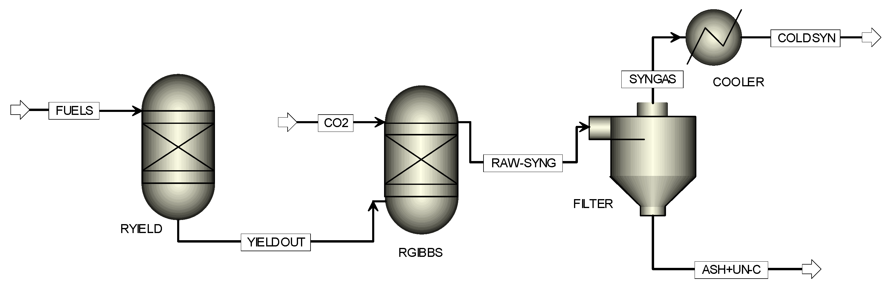
The current process modelling consists of the decomposition of fuel, gasification and equilibrium calculation, as shown in the process flow sheet (Figure 1). The decomposition of coal and biomass takes place in the RYield reactor. The RYield reactor works with the principle of known yield composition, where reaction stoichiometry is not known [28]. The yield composition is given according to the proximate and ultimate data of the fuel samples. In addition, the enthalpy liberated due to the decomposition was based on the heating value of the sample. After decomposition, the elements are oxidised partially with a sub-stoichiometric oxygen supply. Various homogenous and heterogeneous reactions, reported in Table 1, occur in the RGibbs reactor [22,29].
The RGibbs reactor does not need any chemical reaction to be defined. However, it requires operating temperature and pressure to determine possible product compositions under chemical and phase equilibrium. Due to the sub-stoichiometric oxygen supply, carbon may not burn fully. The unburnt carbon and ash are filtered out using a filter in the subsequent stage [30]. After that, the syngas from another filter stream is cooled down using a cooler to a temperature typically used for steam reforming. The details of the unit blocks used in the process modelling are explained in Table 2.
2.2. Model Description and Simulation Procedures
This thermodynamic equilibrium study uses commercial Aspen plus process modelling software, with version V10. The details of the simulation procedures are described in our earlier publication [22]. Hence, only a synopsis of the modelling procedures is described here. The simulation performs mass and energy balance to reach chemical equilibrium. This software features an inbuilt physical, chemical and thermodynamic database for different elements [31]. In this study, the Peng–Robinson–Boston–Mathias (PR–BM) property method is used due to its ability to model non-ideal behaviour under high-temperature entrained flow conditions [25,32]. In Aspen plus simulation, coal and ash were defined as nonconventional components (NC), while conventional components include elemental compositions, CO, H2, CH4, CO2, H2O, H2S and HN3. The NC components were defined based on the proximate and ultimate data of the fuels, as shown in Table 3. HCOALGEN and DCOALIGT features of the software were used to model the enthalpy and density of the nonconventional components.
2.3. Assumption of the Model
The following assumptions are made to model complex entrained flow gasification:
- The gasifier is steady state and isothermal [25]
- The residence time is sufficiently long to reach chemical equilibrium [33]
- Gasification does not produce any NOx or tar under a high-temperature CO2 atmosphere [37]
- There is no separate purge or fuel-conveying gas in the system. CO2 is used as a purge or fuel-conveying gas, which is accounted for in the CO2 stream of the process flow sheet
2.4. Model Validation
The validation of the model was firstly carried out against Texaco entrained flow gasifier data under various operating conditions. The operating conditions reported in Table 4 are adapted from Ref. [25], originally collected from Ref. [31]. The current model was further verified against our large bench-scale entrained flow gasifier data at 1000 °C, as published in the literature [22]. The key operating conditions were 1 gm/min of fuel flow, 12.0 L/min of CO2 and 4.0 L/min of purge N2. However, the details of the reactor configurations and other operating conditions can be found in Ref. [38].
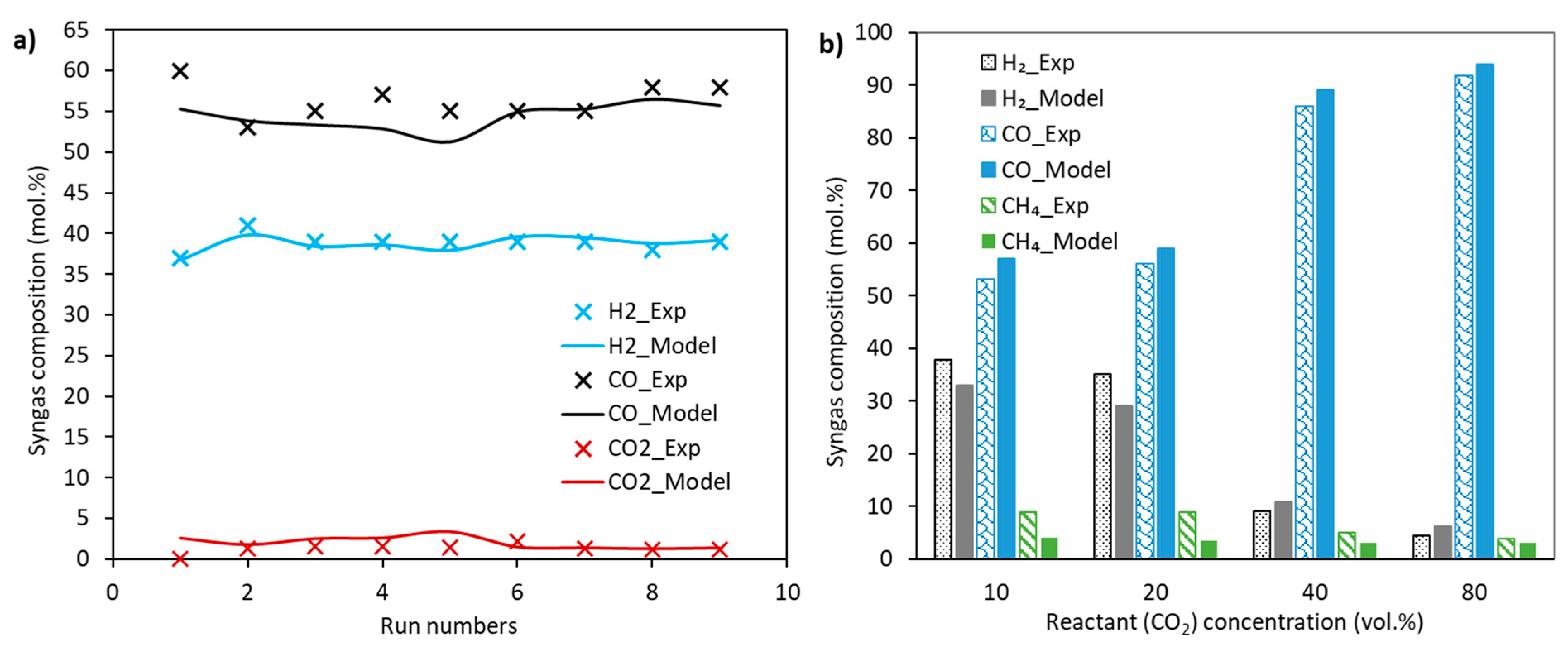
The syngas composition (dry basis), presented in Figure 2, shows that the results obtained from the current model agree with those from the literature. Some discrepancies between the experimental and modelling results are due to the simplification in modelling and error in experimental measurements. Following model validation, a range of sensitivity studies has been carried out under various operating conditions.
3. Results and Discussions
3.1. Effect of Equivalence Ratio on the Gasification Performance of Coal
Figure 3 shows the effect of equivalence ratio (ER, Ø) on carbon conversion at various gasifier temperatures (Tg). It can be seen that increasing the equivalence ratio increases the carbon conversion [39]. The result also indicates that the carbon conversion increases with increasing temperatures [7]. Apparently, at a temperature of 1100 °C, available CO2 is fully consumed. Hence, further increasing the temperature does not affect the carbon conversion [40]. The current result is in line with the results reported by Billaud et al. [39] for wood biomass gasification using steam and CO2 reactants. Noticeably, at an ER of 0.99 (nearly combustion), the carbon conversion is 100% even at a temperature of 800 °C, due to the assumption of infinite residence time to reach equilibrium.
The effect of ER on syngas composition is shown in Figure 4. It is observed that increasing the ER increases the yield of CO up to the ER of 0.66 due to the favoured endothermic Boudouard (Equation (1)) and steam gasification (Equation (2)) reactions [41]. However, the yield of H2 decreases consistently [42] with increasing ER, primarily due to the reverse water gas shift reaction (Equation (4)) [43,44].
The yield of CH4 was negligible, which decreases with increasing ER due to the favoured steam methane reforming reaction (Equation (5)) [45]. The conversion of CO2 (XCO2) was 100% at an ER of 0.66, which dropped to 74% at an ER of 0.99 due to the complete carbon conversion. Similar results have been reported in the literature using different reactants and fuel types [39,41,46]. The results reveal that an ER of 0.33 is most favourable in this study due to significantly higher H2 concentration. It is to be noted that the higher the H2 concentration in syngas, the better the quality is, due to an at least ten times higher heating value compared to CO on a mass basis [22]. Commercial entrained flow gasifiers using steam and oxygen are operated with an ER of <0.5, mostly between 0.3 and 0.4 [45,47]. Hence, the rest of the analysis in the study is conducted under the ER of 0.33.
3.2. Effect of Temperature on the Gasification Performance of Pure Coal
The effect of temperatures on gas composition and CO2 conversion (XCO2) is shown in Figure 5. The modelling was conducted over 800–1600 °C at atmospheric pressure. The result shows that increasing temperature increases the concentration of CO and H2 until CO2 conversion becomes ~100% at around 1100 °C, similar to the findings reported in Ref. [18]. At 1100 °C, the yield of CO and H2 reaches a steady state, indicating that the process reaches equilibrium. The total concentration of CO, H2 and CH4 were summed to 0.99%. The yield of CO was 60% higher than that of H2, leading to the ratio of H2/CO at ~0.40 under steady state conditions. In addition, the result indicates that the Boudouard reaction is more dominant compared to the water–gas shift reaction.
The yield of CH4 is negligible, which decreases exponentially with increasing temperature [44]. The yield of pollutants such as H2S and NH3 are presented in Figure 5b. It is revealed that the yield of NH3 decreases exponentially with increasing temperature, while the H2S remains constant. The results indicate that a gasifier temperature of 1100 °C might be feasible for the gasification of current coal with an adjustment of residence time. A mass balance for PB0 gasification with respect to different temperatures and atmospheric pressure is shown in Table 5. The results show a good match between input and out mass flow rate with insignificant variation, which might be due to a calculation error.
3.3. Effect of Pressure on the Gasification Performance of Pure Coal
The effect of pressure on syngas and CO2 conversion at different temperatures is shown in Figure 6. The result depicts that pressure plays a significant role at a lower temperature under non-steady state conditions. However, upon reaching a steady state, a minor effect is observed [41]. At a temperature of 800 °C, the concentration of CO at one bar was 0.63, which decreased exponentially at 0.26 with increasing pressure at 30 bar. The result can be explained as the conversion of CO2, which decreases with increasing pressure [41]. On the other hand, at a temperature of 1200 °C, the yield of CO decreases slightly with increasing pressure as reactions reach equilibrium [48].
As the pressure increases, the hydrogenation of CO and CO2 become dominant [49]. In addition, the consumption of H2 increases due to the water–gas shift reaction. In contrast, the production of CH4 increases with increasing pressure, and results from the favoured Sabatier reaction in reverse direction [22]. Overall, the effect of pressure on syngas composition is significant before reaching the process steady state, i.e., at a temperature below 1100 °C. The effect of the biomass blending ratio reported in the next section has been tested under atmospheric pressure, similar to the pilot-scale study reported in Ref. [47] for entrained flow gasification of lignites.
3.4. Effect of Blending Ratio on The Co-Gasification Performance
Figure 7 shows the effect of coal and biomass blending ratio on syngas composition. As observed in Figure 7a, increasing the biomass concentration in the blend decreases the yield of CO. However, a drastic decrease in CO was observed with a blending ratio above 50%.
Above 1100 °C, the addition of biomass with 20%, 50% and 80% leads to a decrease in the CO concentration by 0.7, 1.1 and 5.3 percentage points, respectively. Compared to pure coal, pure biomass resulted in a decrease in CO by 10 percentage points. The decrease in CO with increasing biomass ratio is presumably due to the decrease in carbon content in the sample [26]. A decrease in carbon content in the samples between 9.0% and 27% results in the decrease of CO by 1.0 to 10 percentage points. However, further research to fully elucidate the cause of this phenomenon is sought. The conversion of CO2 follows a similar trend to that of CO, meaning that the variation in conversion is negligible below PB50, while significant over a biomass ratio of 50% (Figure 7h).
According to Figure 7b, increasing biomass ratio leads to an increase in the concentration of H2, reaching a maximum at PB50. Further increasing the biomass leads to a decrease in the concentration of H2 significantly, particularly for pure biomass. The increase in H2 yield up to PB50 might be explained by the higher gasification rate and higher concentration of H in biomass [38]. Increasing H2 concentration with increasing biomass ratio is reported in the literature [50]. However, a thorough study to find the cause of reduction in H2 yield using biomass over PB50 needs to be undertaken in the future.
The syngas composition reaches a steady state at 1100 °C with an H2/CO ratio of about 0.40 (Figure 7g). According to Figure 7c, the yield of CH4 was negligible, with almost no difference up to PB50. However, using PB80 and PB10, the concentration of CH4 decreases drastically and become almost nil at a temperature over 900 °C. The concentration of H2O overlapped among PB0, PB20 and PB50, above which an increase with increasing the biomass ratio was observed (Figure 7d). The final compositions of CH4 and H2O are governed by the reverse water–gas shift and Sabatier reactions.
The yield of two pollutants—H2S and NH3—decrease with increasing biomass concentration, which is in the ppm range (Figure 7e,f). The pollutant emission from pure biomass is nearly zero. A proportional relationship between inherent N and S content and with those of NH3 and H2S is observed. While comparing coal and biomass, the N and S content in biomass are 10 and 50 times lower than in coal. Thus, increasing biomass concentration in the blend results in the decrease of H2S and NH3. The overall gas composition suggests that biomass blending up to 50% is optimum for the fuels studied.
Figure 8 shows the effect of biomass ratio on total syngas, LHV and CGE. It is observed that increasing biomass ratio increases the total syngas flow rate up to PB50. Further increasing the biomass in the blend leads to a decrease in the total syngas flow rate due to the significant decrease in carbon for gasification reactions [26]. The LHV overlaps each other among PB0, PB20 and PB50 due to the insignificant variation in the concentration of CO and H2. However, increasing the biomass ratio above 50% results in the decrease of LHV consistently [38]. A maximum LHV of 12 MJ/kg and a CGE of 78% was determined using PB50. Due to the insignificant difference in LHV among the samples, the CGE is predominantly governed by total syngas yield at different biomass ratios. Figure 8d shows the relationship among CGE, the total syngas and temperature using PB50. It is revealed that increasing temperature increases the total syngas flow rate and thereby the CGE [7].
4. Conclusions
In this study, an assessment of coal and biomass co-gasification has been carried out using Aspen plus process simulator. The effect of equivalence ratio, temperature, pressure and biomass to coal ratio have been investigated using CO2 reactant. The results show that increasing temperature increases the yield of CO and H2 up to the steady state temperature (1100 °C). The pressure effect is significant only at a lower temperature (<1100 °C), considering syngas composition. Increasing biomass ratio up to 50% in the blends increases the concentration of H2, above which a significant drop appears. However, the concentration of CO decreases consistently with increasing biomass ratio in the blend, with very little variation up to 50% biomass. The blended sample with 50% biomass resulted in a maximum LHV of 12 MJ/kg and a CGE of 78%. The concentration of pollutants decreased consistently with increasing biomass ratio. Thus, co-gasification using CO2 reactants can potentially increase gasification efficiency besides reducing pollutant emissions.
Author Contributions
Conceptualization, M.S.; Formal analysis, M.S.; Investigation, M.S.; Methodology, M.S.; Project administration, S.B.; Supervision, S.B.; Validation, M.S.; Writing—original draft, M.S.; Writing—review & editing, M.S. and S.B. All authors have read and agreed to the published version of the manuscript.
Funding
This research received no external funding.
Conflicts of Interest
The authors declare no conflict of interest.
References
- Le Quéré, C.; Andrew, R.M.; Canadell, J.G.; Sitch, S.; Korsbakken, J.I.; Peters, G.P.; Manning, A.C.; Boden, T.A.; Tans, P.P.; Houghton, R.A.; et al. Global carbon budget 2016. Earth Syst. Sci. Data 2016, 8, 1–45. [Google Scholar] [CrossRef] [Green Version]
- Bouckaert, S.; Pales, A.F.; McGlade, C.; Remme, U.; Wanner, B.; Varro, L.; D’Ambrosio, D.; Thomas, S. Net Zero by 2050: A Roadmap for the Global Energy Sector; International Energy Agency Report: Paris, France, 2021.
- Ng, K.S.; Lopez, Y.; Campbell, G.M.; Sadhukhan, J. Heat integration and analysis of decarbonised IGCC sites. Chem. Eng. Res. Des. 2010, 88, 170–188. [Google Scholar] [CrossRef] [Green Version]
- Ayub, H.; Park, S.; Binns, M. Biomass to Syngas: Modified Non-Stoichiometric Thermodynamic Models for the Downdraft Biomass Gasification. Energies 2020, 13, 5668. [Google Scholar] [CrossRef]
- Ferreira, S.; Monteiro, E.; Brito, P.; Vilarinho, C. A Holistic Review on biomass gasification modified equilibrium models. Energies 2019, 12, 160. [Google Scholar] [CrossRef] [Green Version]
- Ahmed, I.; Gupta, A. Characteristics of cardboard and paper gasification with CO2. Appl. Energy 2009, 86, 2626–2634. [Google Scholar] [CrossRef]
- Oh, G.; Ra, H.W.; Yoon, S.M.; Mun, T.Y.; Seo, M.W.; Lee, J.G.; Yoon, S.J. Gasification of coal water mixture in an entrained-flow gasifier: Effect of air and oxygen mixing ratio. Appl. Therm. Eng. 2018, 129, 657–664. [Google Scholar] [CrossRef]
- Renganathan, T.; Yadav, M.; Pushpavanam, S.; Voolapalli, R.; Cho, Y. CO2 utilisation for gasification of carbonaceous feedstocks: A thermodynamic analysis. Chem. Eng. Sci. 2012, 83, 159–170. [Google Scholar] [CrossRef]
- Kirtania, K.; Bhattacharya, S. CO2 gasification behavior of biomass chars in an entrained flow reactor. Biomass Convers. Biorefin. 2016, 6, 49–59. [Google Scholar] [CrossRef]
- Xu, T.; Bhattacharya, S. Entrained flow gasification behaviour of Victorian brown coal char at low temperature. Fuel 2018, 234, 549–557. [Google Scholar] [CrossRef]
- Sircar, I.; Sane, A.; Wang, W.; Gore, J.P. Experimental and modeling study of pinewood char gasification with CO2. Fuel 2014, 119, 38–46. [Google Scholar] [CrossRef]
- Nilsson, S.; Gómez-Barea, A.; Ollero, P. Gasification of char from dried sewage sludge in fluidised bed: Reaction rate in mixtures of CO2 and H2O. Fuel 2013, 105, 764–768. [Google Scholar] [CrossRef]
- Tanner, J.; Bhattacharya, S. Kinetics of CO2 and steam gasification of Victorian brown coal chars. Chem. Eng. J. 2016, 285, 331–340. [Google Scholar] [CrossRef]
- Chmielniak, T.; Sciazko, M.; Tomaszewicz, G.; Tomaszewicz, M. Pressurized CO2-enhanced gasification of coal. J. Therm. Anal. Calorim. 2014, 117, 1479–1488. [Google Scholar] [CrossRef]
- Shahabuddin, M.; Bhattacharya, S. Effect of reactant types (steam, CO2 and steam+ CO2) on the gasification performance of coal using entrained flow gasifier. Int. J. Energy Res. 2021, 45, 9492–9501. [Google Scholar] [CrossRef]
- Shahabuddin, M.; Kibria, M.A.; Bhattacharya, S. Effect of pore diffusion on the gasification characteristics of coal char under CO2 atmosphere. Int. J. Energy Clean Environ. 2021, 22, 85–102. [Google Scholar] [CrossRef]
- Irfan, M.F.; Usman, M.R.; Kusakabe, K. Coal gasification in CO2 atmosphere and its kinetics since 1948: A brief review. Energy 2011, 36, 12–40. [Google Scholar] [CrossRef]
- Sadhwani, N.; Li, P.; Eden, M.R.; Adhikari, S. Process Modeling of Fluidized Bed Biomass-CO2 Gasification using ASPEN Plus. Computer Aided Chemical Engineering; Elsevier: Amsterdam, The Netherlands, 2017; pp. 2509–2514. [Google Scholar]
- Li, H.; Yu, Y.; Han, M.; Lei, Z. Simulation of coal char gasification using O2/CO2. Int. J. Coal Sci. Technol. 2014, 1, 81–87. [Google Scholar] [CrossRef] [Green Version]
- Klimanek, A.; Bigda, J. CFD modelling of CO2 enhanced gasification of coal in a pressurised circulating fluidised bed reactor. Energy 2018, 160, 710–719. [Google Scholar] [CrossRef]
- Shahabuddin, M.; Krishna, B.B.; Bhaskar, T.; Perkins, G. Advances in the thermo-chemical production of hydrogen from biomass and residual wastes: Summary of recent techno-economic analyses. Bioresour. Technol. 2020, 299, 122557. [Google Scholar] [CrossRef]
- Shahabuddin, M.; Bhattacharya, S. Process modelling for the production of hydrogen-rich gas from gasification of coal using oxygen, CO2 and steam reactants. Int. J. Hydrogen Energy 2021, 46, 24051–24059. [Google Scholar] [CrossRef]
- Ng, K.S.; Zhang, N.; Sadhukhan, J. Techno-economic analysis of polygeneration systems with carbon capture and storage and CO2 reuse. Chem. Eng. J. 2013, 219, 96–108. [Google Scholar] [CrossRef] [Green Version]
- Shahabuddin, M.; Bhattacharya, S.; Srivatsa, S.C. Co-slagging characteristics of coal and biomass ashes considering entrained flow slagging gasifier. Biomass Convers. Biorefin. 2021, 1–10. [Google Scholar] [CrossRef]
- Ali, D.A.; Gadalla, M.; Abdelaziz, O.; Hulteberg, C.P.; Ashour, F.H. Co-gasification of coal and biomass wastes in an entrained flow gasifier: Modelling, simulation and integration opportunities. J. Nat. Gas Sci. Eng. 2017, 37, 126–137. [Google Scholar] [CrossRef]
- Kuo, P.-C.; Wu, W. Thermodynamic analysis of a combined heat and power system with CO2 utilisation based on co-gasification of biomass and coal. Chem. Eng. Sci. 2016, 142, 201–214. [Google Scholar] [CrossRef]
- Castaldi, M.; Dooher, J. Investigation into a catalytically controlled reaction gasifier (CCRG) for coal to hydrogen. Int. J. Hydrogen Energy 2007, 32, 4170–4179. [Google Scholar] [CrossRef]
- Aspen Plus. Aspen Plus User Guide, Version 10.2; Aspen Technology: Burlington, MA, USA, 2010; Chapter 10; pp. 2–28. [Google Scholar]
- Marcantonio, V.; Bocci, E.; Monarca, D. Development of a chemical quasi-equilibrium model of biomass waste gasification in a fluidised-bed reactor by using Aspen Plus. Energies 2020, 13, 53. [Google Scholar] [CrossRef] [Green Version]
- Yoshida, H.; Kiyono, F.; Tajima, H.; Yamasaki, A.; Ogasawara, K.; Masuyama, T. Two-stage equilibrium model for a coal gasifier to predict the accurate carbon conversion in hydrogen production. Fuel 2008, 87, 2186–2193. [Google Scholar] [CrossRef]
- Xiangdong, K.; Zhong, W.; Wenli, D.; Feng, Q. Three stage equilibrium model for coal gasification in entrained flow gasifiers based on aspen plus. Chin. J. Chem. Eng. 2013, 21, 79–84. [Google Scholar]
- Visconti, A.; Miccio, M.; Juchelková, D. An aspen plus tool for simulation of lignocellulosic biomass pyrolysis via equilibrium and ranking of the main process variables. Int. J. Math. Models Methods Appl. Sci. 2015, 9, 71–86. [Google Scholar]
- Suwatthikul, A.; Limprachaya, S.; Kittisupakorn, P.; Mujtaba, I.M. Simulation of steam gasification in a fluidised bed reactor with energy self-sufficient condition. Energies 2017, 10, 314. [Google Scholar] [CrossRef]
- Dai, Z.; Gong, X.; Guo, X.; Liu, H.; Wang, F.; Yu, Z. Pilot-trial and modeling of a new type of pressurised entrained-flow pulverised coal gasification technology. Fuel 2008, 87, 2304–2313. [Google Scholar] [CrossRef]
- Zhang, Z.F.; Tang, L.Y.; Lu, Q.Y.; Zhang, W.X.; He, Z.Z.; BI, D.H. Pulverised coal gasification simulation based on aspen plus software. Chem. Fertil. Des. 2008, 3. Available online: http://en.cnki.com.cn/Article_en/CJFDTOTAL-HFSJ200803004.htm (accessed on 4 November 2021).
- Barrera-Zapata, R.; Salazar, C.; Pérez, J.F. Thermochemical Equilibrium Model of Synthetic Natural Gas Production from Coal Gasification Using Aspen Plus. Int. J. Chem. Eng. 2014, 2014, 1–18. [Google Scholar] [CrossRef]
- Shahabuddin, M.; Kibria, M.; Bhattacharya, S. Evaluation of high-temperature pyrolysis and CO2 gasification performance of bituminous coal in an entrained flow gasifier. J. Energy Inst. 2020, 94, 294–309. [Google Scholar] [CrossRef]
- Shahabuddin, M.; Bhattacharya, S. Enhancement of performance and emission characteristics by co-gasification of biomass and coal using an entrained flow gasifier. J. Energy Inst. 2021, 95, 166–178. [Google Scholar] [CrossRef]
- Billaud, J.; Valin, S.; Peyrot, M.; Salvador, S. Influence of H2O, CO2 and O2 addition on biomass gasification in entrained flow reactor conditions: Experiments and modelling. Fuel 2016, 166, 166–178. [Google Scholar] [CrossRef] [Green Version]
- Tanner, J. High Temperature, Entrained Flow Gasification of Victorian Brown Coals and Rhenish Lignites. Ph.D. Thesis, Monash University, Clayton, Australia, 2015. [Google Scholar]
- Adnan, M.A.; Hossain, M.M. Gasification performance of various microalgae biomass—A thermodynamic study by considering tar formation using Aspen plus. Energy Convers. Manag. 2018, 165, 783–793. [Google Scholar] [CrossRef]
- Villarini, M.; Marcantonio, V.; Colantoni, A.; Bocci, E. Sensitivity Analysis of Different Parameters on the Performance of a CHP Internal Combustion Engine System Fed by a Biomass Waste Gasifier. Energies 2019, 12, 688. [Google Scholar] [CrossRef] [Green Version]
- Adnan, M.A.; Hossain, M.M. Gasification of various biomasses including microalgae using CO2—A thermodynamic study. Renew. Energy 2018, 119, 598–607. [Google Scholar] [CrossRef]
- Pala, L.P.R.; Wang, Q.; Kolb, G.; Hessel, V. Steam gasification of biomass with subsequent syngas adjustment using shift reaction for syngas production: An Aspen Plus model. Renew. Energy 2017, 101, 484–492. [Google Scholar] [CrossRef]
- Doherty, W.; Reynolds, A.; Kennedy, D. The effect of air preheating in a biomass CFB gasifier using ASPEN Plus simulation. Biomass Bioenergy 2009, 33, 1158–1167. [Google Scholar] [CrossRef] [Green Version]
- Turn, S.; Kinoshita, C.; Zhang, Z.; Ishimura, D.; Zhou, J. An experimental investigation of hydrogen production from biomass gasification. Int. J. Hydrogen Energy 1998, 23, 641–648. [Google Scholar] [CrossRef]
- Ünlü, A.; Kayahan, U.; Argönül, A.; Ziypak, M.; Akça, A. Pilot scale entrained flow gasification of Turkish lignites. J. Energy Inst. 2017, 90, 159–165. [Google Scholar] [CrossRef]
- Molino, A.; LaRocca, V.; Chianese, S.; Musmarra, D. Biofuels Production by Biomass Gasification: A Review. Energies 2018, 11, 811. [Google Scholar] [CrossRef] [Green Version]
- AlNouss, A.; McKay, G.; Al-Ansari, T. Production of syngas via gasification using optimum blends of biomass. J. Clean. Prod. 2020, 242, 118499. [Google Scholar] [CrossRef]
- Li, K.; Zhang, R.; Bi, J. Experimental study on syngas production by co-gasification of coal and biomass in a fluidised bed. Int. J. Hydrogen Energy 2010, 35, 2722–2726. [Google Scholar] [CrossRef]
Figure 1.
Process flow sheet of the thermodynamic equilibrium model.

Figure 2.
Model validation against (a) commercial-scale Texaco gasifier (adapted with permission from [25]) and (b) large bench-scale entrained flow gasifier data (adapted with permission from [22]).

Figure 3.
Effect of temperature on carbon conversion using different equivalence ratios at atmospheric pressure.
Figure 3.
Effect of temperature on carbon conversion using different equivalence ratios at atmospheric pressure.

Figure 4.
Effect of equivalence ratio on syngas composition.

Figure 5.
Effect of temperature on gas composition. (a) CO, H2, H2/CO and XCO2; (b) H2S and NH3.

Figure 6.
The effect of pressure on syngas composition and CO2 conversion at two different temperatures of (a) 800 °C and (b) 1200 °C.
Figure 6.
The effect of pressure on syngas composition and CO2 conversion at two different temperatures of (a) 800 °C and (b) 1200 °C.

Figure 7.
Effect of coal and biomass ratio on syngas composition and CO2 conversion at different temperatures: PB0: black, PB20: red, PB50: blue, PB80: green, PB100: purple. (a) CO; (b) H2; (c) CH4; (d) H2O; (e) H2S; (f) NH3; (g) H2/CO; (h) XCO2; (i) CO2.
Figure 7.
Effect of coal and biomass ratio on syngas composition and CO2 conversion at different temperatures: PB0: black, PB20: red, PB50: blue, PB80: green, PB100: purple. (a) CO; (b) H2; (c) CH4; (d) H2O; (e) H2S; (f) NH3; (g) H2/CO; (h) XCO2; (i) CO2.

Figure 8.
Effect of biomass ratio on total gas flow rate, LHV and CGE at different temperatures (a) total gas flow rate for all samples; (b) LHV; (c) CGE; (d) total gas flow rate and CGE for PB50.
Figure 8.
Effect of biomass ratio on total gas flow rate, LHV and CGE at different temperatures (a) total gas flow rate for all samples; (b) LHV; (c) CGE; (d) total gas flow rate and CGE for PB50.


Table 1.
Major gasification reactions (adapted with permission from [22]).
Table 1.
Major gasification reactions (adapted with permission from [22]).
| Reaction Name | Chemical Formula | Enthalpy | Eq. No. |
|---|---|---|---|
| Boudouard reaction | C(s) + CO2 → 2CO | (ΔH = +159.7) | (1) |
| Steam gasification | C(s) + H2O ⇌ CO + H2 | (ΔH = +118.9) | (2) |
| Hydrogen combustion | C(s) + 2H2 ⇌ CH4 | (ΔH = −88.4) | (3) |
| Water–gas shift reaction | CO + H2O ⇌ CO2 + H2 | (ΔH = −41.1) | (4) |
| Steam methane reforming | CH4 + H2O ⇌ CO + 3H2 | (ΔH = +206.3) | (5) |
| Dry methane reforming | CH4 + CO2 ⇌ 2CO + 2H2 | (ΔH = −247) | (6) |
| Sabatier reaction | CO2 + 4H2 ⇌ CH4 + 2H2O | (ΔH = +73) | (7) |
Table 2.
Description of the unit blocks used in the process modelling [28].
Table 2.
Description of the unit blocks used in the process modelling [28].
| Type | Model | Schematic | Descriptions and Operating Conditions |
|---|---|---|---|
| Reactors | RYield |  | This unit is used as a decomposition reactor to break down coal/biomass into components based on the proximate and ultimate data. This reactor is used when component yield distribution is the only known parameter. This reactor is isothermal, and the operating parameters for this reactor are temperature and pressure. |
| RGibbs |  | This equilibrium reactor works based on rigorous or multiphase equilibrium according to the Gibbs free energy minimisation technique, subject to atom balance constraints. This model does not require reaction stoichiometry or reaction kinetics to be specified and can determine phase equilibrium without any chemical reaction. The operating parameters are either temperature and pressure or pressure and enthalpy. This model is used for thermodynamic equilibrium calculation in the gasifier to determine the final syngas composition. | |
| Filter | SSplit |  | The SSplit is the sub-stream splitter. This unit divides feed based on splits specified for each sub-stream. The operating parameter for this unit is split fraction. The current modelling study used this unit to separate ash and unburnt carbon from the syngas. |
| Heat Exchangers | Cooler |  | This unit is the thermal and phase state changer, which can model heater, cooler and condenser. The operating parameters for this unit are temperature and pressure. In this study, this unit is used to drop the hot syngas temperature to 225 °C—a typical temperature used in steam reforming to produce hydrogen. |
Table 3.
Chemical properties of coal and biomass samples (wt.%, dry basis).
| Sample * | Proximate Analysis | Ultimate Analysis | LHV (MJ/kg) | ||||||||
|---|---|---|---|---|---|---|---|---|---|---|---|
| Moisture | VM | FC | Ash | C | H | N | S | O | Ash | ||
| PB0 | 3.10 | 30.61 | 57.79 | 11.60 | 74.19 | 4.59 | 1.52 | 0.55 | 7.55 | 11.60 | 30.26 |
| PB20 | 3.13 | 37.69 | 52.81 | 9.50 | 67.57 | 5.12 | 1.15 | 0.38 | 16.28 | 9.50 | 27.72 |
| PB50 | 3.17 | 48.31 | 45.39 | 6.30 | 62.51 | 5.63 | 0.78 | 0.23 | 24.55 | 6.30 | 23.91 |
| PB80 | 3.20 | 58.92 | 37.88 | 3.20 | 57.29 | 6.21 | 0.36 | 0.08 | 32.86 | 3.20 | 20.09 |
| PB100 | 3.23 | 66.02 | 32.88 | 1.10 | 53.89 | 6.54 | 0.14 | 0.01 | 38.32 | 1.10 | 17.55 |
* The numerical value in the sample name denotes its percentage of pine bark biomass (PB), which is balanced to 100% with coal.
Table 4.
Operating conditions of Texaco entrained flow gasifier (adapted with permission from [25]).
Table 4.
Operating conditions of Texaco entrained flow gasifier (adapted with permission from [25]).
| Run | Feed Rate (kg/h) | Reactant/Fuel Ratio | |||
|---|---|---|---|---|---|
| Fuel | O2 | Steam | O2/Fuel | Steam/Fuel | |
| Run-1 | 275.976 | 238.995 | 66.510 | 0.866 | 0.241 |
| Run-2 | 292.248 | 224.446 | 92.935 | 0.768 | 0.318 |
| Run-3 | 295.920 | 240.583 | 91.439 | 0.813 | 0.309 |
| Run-4 | 286.056 | 230.847 | 92.396 | 0.807 | 0.323 |
| Run-5 | 257.804 | 212.946 | 90.747 | 0.826 | 0.352 |
| Run-6 | 315.828 | 244.451 | 91.906 | 0.774 | 0.291 |
| Run-7 | 327.492 | 254.134 | 92.353 | 0.776 | 0.282 |
| Run-8 | 331.668 | 264.339 | 81.922 | 0.797 | 0.247 |
| Run-9 | 316.044 | 248.727 | 84.700 | 0.787 | 0.268 |
Table 5.
Mass balance for the gasification of pure coal (PB0) at different temperatures and atmospheric pressure.
Table 5.
Mass balance for the gasification of pure coal (PB0) at different temperatures and atmospheric pressure.
| Tg (°C) | PB0 (kg/h) | Feed CO2 (kg/h) | Total in (kg/h) | CO (kg/h) | H2 (kg/h) | CH4 (kg/h) | CO2 (kg/h) | H2O (kg/h) | H2S (kg/h) | NH3 (kg/h) | Unconverted C (kg/h) | Ash (kg/h) | Total Out (kg/h) |
|---|---|---|---|---|---|---|---|---|---|---|---|---|---|
| 800 | 100 | 110 | 210.0 | 134.62 | 4.25 | 0.39 | 20.35 | 3.35 | 0.56 | 0.0006 | 35.56 | 11.6 | 210.7 |
| 900 | 100 | 110 | 210.0 | 157.19 | 4.55 | 0.17 | 5.36 | 1.11 | 0.56 | 0.0004 | 30.14 | 11.6 | 210.7 |
| 1000 | 100 | 110 | 210.0 | 163.17 | 4.65 | 0.08 | 1.52 | 0.40 | 0.56 | 0.0002 | 28.69 | 11.6 | 210.7 |
| 1100 | 100 | 110 | 210.0 | 164.83 | 4.69 | 0.04 | 0.51 | 0.17 | 0.56 | 0.0002 | 28.29 | 11.6 | 210.7 |
| 1200 | 100 | 110 | 210.0 | 165.36 | 4.70 | 0.02 | 0.20 | 0.08 | 0.55 | 0.0001 | 28.16 | 11.6 | 210.7 |
| 1300 | 100 | 110 | 210.0 | 165.56 | 4.71 | 0.01 | 0.09 | 0.04 | 0.55 | 0.0001 | 28.11 | 11.6 | 210.7 |
| 1400 | 100 | 110 | 210.0 | 165.65 | 4.71 | 0.01 | 0.05 | 0.02 | 0.55 | 0.0001 | 28.09 | 11.6 | 210.7 |
| 1500 | 100 | 110 | 210.0 | 165.69 | 4.72 | 0.01 | 0.03 | 0.01 | 0.55 | 0.0001 | 28.08 | 11.6 | 210.7 |
| 1600 | 100 | 110 | 210.0 | 165.71 | 4.72 | 0.00 | 0.02 | 0.01 | 0.55 | 0.0000 | 28.08 | 11.6 | 210.7 |
Publisher’s Note: MDPI stays neutral with regard to jurisdictional claims in published maps and institutional affiliations. |
© 2021 by the authors. Licensee MDPI, Basel, Switzerland. This article is an open access article distributed under the terms and conditions of the Creative Commons Attribution (CC BY) license (https://creativecommons.org/licenses/by/4.0/).
Share and Cite
MDPI and ACS Style
Shahabuddin, M.; Bhattacharya, S. Co-Gasification Characteristics of Coal and Biomass Using CO2 Reactant under Thermodynamic Equilibrium Modelling. Energies 2021, 14, 7384. https://0-doi-org.brum.beds.ac.uk/10.3390/en14217384
AMA Style
Shahabuddin M, Bhattacharya S. Co-Gasification Characteristics of Coal and Biomass Using CO2 Reactant under Thermodynamic Equilibrium Modelling. Energies. 2021; 14(21):7384. https://0-doi-org.brum.beds.ac.uk/10.3390/en14217384
Chicago/Turabian StyleShahabuddin, M., and Sankar Bhattacharya. 2021. "Co-Gasification Characteristics of Coal and Biomass Using CO2 Reactant under Thermodynamic Equilibrium Modelling" Energies 14, no. 21: 7384. https://0-doi-org.brum.beds.ac.uk/10.3390/en14217384
Note that from the first issue of 2016, this journal uses article numbers instead of page numbers. See further details here.