
Two-Coil Receiver for Electrical Vehicles in Dynamic Wireless Power Transfer


1
Department of Industrial and Information Engineering and Economics, University of L’Aquila, 67100 L’Aquila, Italy
2
Department of Astronautics, Electrical and Energetics Engineering, Sapienza University of Rome, 00184 Rome, Italy
*
Author to whom correspondence should be addressed.
Energies 2021, 14(22), 7790; https://0-doi-org.brum.beds.ac.uk/10.3390/en14227790
Submission received: 11 October 2021
/
Revised: 8 November 2021
/
Accepted: 15 November 2021
/
Published: 21 November 2021
(This article belongs to the Special Issue Advanced Wireless Power Transfer Technologies)
Abstract
:Dynamic wireless power transfer (DWPT) of electric vehicles (EVs) is the future of urban mobility. The DWPT is often based on a series of short track pads embedded in road pavement that wirelessly transfers electrical energy to EVs equipped with a pickup coil for battery charging. An open problem with this technology is the variation of the coupling factor as a vehicle switches from one transmitting coil to another during its motion. This can cause a significant change in power with possible power spikes and holes. In order to overcome these issues, a new architecture is here proposed based on two pick-up coils mounted in the vehicle underneath. These identical receiver coils are placed in different positions under the vehicle (one in front and the other in the rear) and are activated one at a time so that inductive coupling is always good enough. This innovative configuration has two main advantages: (i) it maintains a nearly constant coupling factor, as well as efficiency and transferred power, as the vehicle moves along the electrified road; (ii) it significantly reduces the cost of road infrastructure. An application is presented to verify the proposed two-coil architecture in comparison with the traditional one-coil. The results of the investigation show the significant improvement achieved in terms of maximum power variation which is nearly stable with the proposed two-coil architecture (only 2.8% variation) while there are many power holes with the traditional single coil architecture. In addition, the number of the required transmitting coils is significantly reduced due to a larger separation between adjacent coils.
1. Introduction
The development of road transport in the near future will be based on the widespread use of electric vehicles (EVs). They are currently equipped with an internal battery that must be periodically charged by a plug-in connection at home or at a charging station. One of the most critical issues in EVs is the battery, which has high cost, high weight, and long recharge time. All these drawbacks today are the main impediment to the spread of EVs. In the future, a wide diffusion could be fostered by new technologies such as wireless power transfer (WPT) that will certainly allow overcoming the above-mentioned obstacles. The working principles of this technology are well described in [1,2,3]. In order to increase safety, comfort, and range, the idea is to recharge the battery using a wireless connection based on inductive coupling instead of using a plug-in connection. At present, the resonant inductive coupling technology is almost commercially ready for stationary EVs by using a fixed transmitter coil embedded in a parking area and a receiver coil mounted on board the EV [4]. Several studies were presented to increase the system performance and to verify the compliance with the safety limits [5,6]. Moreover, advanced techniques to reduce the magnetic field in the environment were investigated [7]. In perspective, the idea is to create an electric infrastructure (i.e., electrified roads) where EVs can wirelessly recharge while moving along the roads and, hence, increasing their range significantly [8,9,10]. This type of WPT technology is known as dynamic wireless power transfer (DWPT). The effort required for the implementation of the DWPT will be very large and will involve many players such as car manufacturers, electricity boards, traffic management, etc. Road electrification is mainly based on two different architectures for the transmitter coils: a series of short-track pads or a long-track coil. In both cases, the transmitter coils will be embedded in the road pavement and powered by an AC or DC bus connected to the main network, and every EV must be equipped with a receiver coil in order to be recharged. Many experimental demonstrations carried out so far on DWPT adopt short-track architecture. By this solution, the transmitter coils will be switched on, one at a time, only when an EV passes over them. A critical electrical aspect of the short-track DWPT is provided by the strong variability of power absorbed by the EVs and delivered by the AC main grid. Indeed, the transmitter and receiver coils are rarely perfectly aligned due to the EV movement. Therefore, the coupling factor between the coils is strongly variable, being dependent on the position of the onboard receiver coil relative to the fixed position of the transmitter coil. Since the coupling factor is time variant, there are some reciprocal positions/instants where it is at its maximum (perfect alignment of the coils), but there are also other positions/instants where it is close to zero (large misalignment of the coils or deactivated transmitter coil). This results in significant power variation with spikes and holes. Investigations of the short pad architecture can be found in [8] where a demonstration system is presented and tested while showing good performance. Additional insight on several aspects such as efficiency, EMF emission, etc., are presented in [9,10]. In all the available literature, the problem of the power discontinuity is evident, and the oscillation of power is still an open problem.
The aim of this work is the stabilization of the transferred power, which is very important for both the AC power grid and the EV battery charging on board the EV. Some studies have been published in technical literature to solve these problems [11,12]; however, they are mainly based on the use of multiple overlapped transmitter coils. This solution when adopted for the transmitter permits reducing power variation and spikes but with a significant increase in road infrastructure cost. Another solution was proposed in [13] where a complex vehicle assembly (VA) composed of three overlapped coils was presented while retaining an unchanged traditional architecture of the transmitting short pad coil. Here, we propose a new solution to reduce the cost of road infrastructure and, at the same time, to guarantee an almost stable power consumption of an EV in motion. The proposed solution is based on a new architecture of the VA coils in which the EV is equipped with two independent receiver coils mounted one in the front and the other in the rear of the vehicle underneath. The two coils operate one at a time. The receiver coil to be used is selected to maximize inductive coupling with the transmitter coil depending on mutual positions. On the ground assembly (GA), the necessary number of transmitter coils and electronics is reduced as much as possible by increasing the separation between adjacent transmitter coils along the electrified road, thus reducing the cost of the road infrastructure. The first section deals with the state of art of the DWPT system and the simulation tools able to analyze these systems. Then, the proposed architecture based on two pick-up coils is presented and described. Finally, an application of the proposed solution is compared with the traditional approach (i.e., single coil receiver). The first advantage of the proposed approach is the reduction in the number of GA coils required, with a significant reduction in the cost of the infrastructure. In addition, charging power and efficiency are nearly constant with a dual benefit for the AC grid and for the vehicle where the battery is charged with a constant current, reducing battery stress and improving its lifespan.
2. Dynamic WPT System
2.1. WPT Equivalent Circuit and Compensation Networks
Since the time constant of the electrical problem is much smaller than that related to the velocity of the EV, the coupling between the fixed transmitting coil and the mobile receiving coil can be analyzed as a sequence of static configurations, each characterized by a variable reciprocal position of the coils, without considering the movement. It is assumed that the transmitter coils are activated, one at a time, only when the receiver is above the transmitter or in close proximity. With this hypothesis, the analysis of the coupling between transmitting and receiving coils can be extended to all the coils along the electrified road. The configuration under examination is, therefore, composed of a single transmitting coil and a single receiving coil with variable reciprocal position. The coupled coils can be modeled as two coupled inductors in an equivalent circuit representation. To improve electrical performance in terms of efficiency and transferred power, the system resonates by introducing compensation networks on both the transmitter and receiver sides to compensate for the inductive reactance of the inductors using capacitive loads. The simplest compensation network is a capacitor connected in series to the inductor on both sides of the circuit (transmitter and receiver). This topology known as series–series (SS) compensation is adopted in this study for its simplicity, excellent performance, and other important reasons that will be described below.
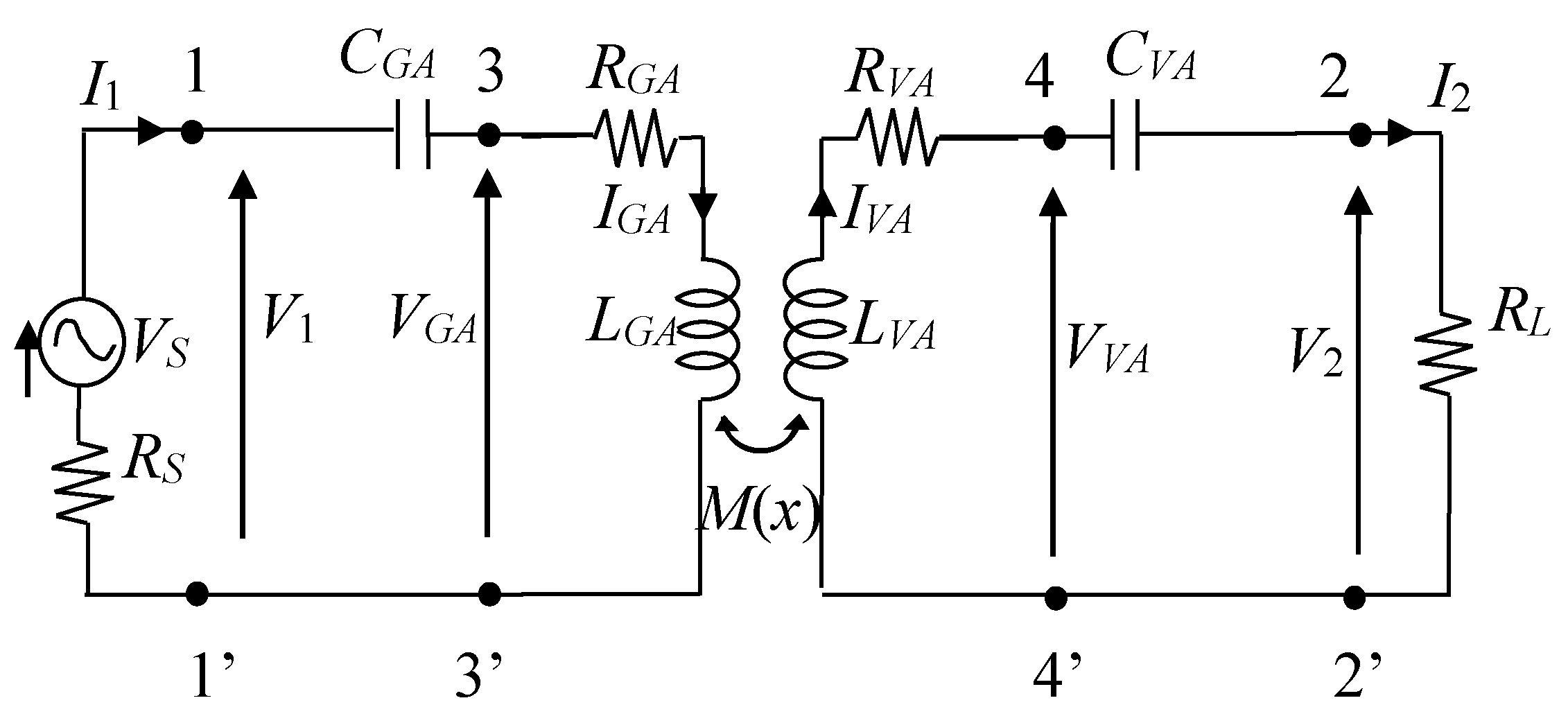
An automotive WPT system is composed of the electrical and electronic components of the ground transmitter named GA and the electrical and electronic components of the onboard EV receiver named VA. The entire system is, therefore, composed of many electrical and electronic components, but to simplify the study, the system can be modeled at resonance with an equivalent circuit with all analog components, as shown in Figure 1, where VS is the voltage source, RS is its internal resistance, RL is the equivalent resistive load, RGA and LGA are the GA coil resistance and self-inductance, and RVA and LVA are the VA coil resistance and self-inductance. The mutual inductance between GA and VA coils is modelled by , where k is the coupling factor. The equivalent series resistances (ESR) and the self-inductances of the coils are not significantly dependent on the movement of the EV, which mainly affects the coupling factor k and consequently the mutual inductance M. The latter varies during the movement of the vehicle and its value is maximum when the transmitter and receiver coils are aligned. The SS compensation has been adopted here as it ensures high efficiency for the considered configuration, and the values of the compensation capacitors are not affected by the M variation unlike other compensation topologies. It implies that the system does not have to be retuned for any reciprocal position of the GA and VA coils as it maintains the resonance for any value of M. This is a very important feature for DWPT systems.
Assuming f0 to be the resonance frequency, the SS compensation capacitors CGA and CVA are given by the following [3]:
where it can be noted that CGA and CVA depend only on self-inductances and the resonance frequency.
The analysis of the circuit in Figure 1 allows predicting the electrical performance of the WPT system, mainly provided by the real power P2 at port 2-2′ delivered to the load RL and by the power transfer efficiency η given by the following:
where P1 is the input real power at port 1-1′. In the case of the M variable with reciprocal coils position (i.e., M = M(x) when assuming x to be the separation between the centers of the GA and VA coils along the road (x-axis) and zero lateral offset in y direction), efficiency and transferred power depend on x and (3) becomes the following [14].
From (4), it can be easily observed that efficiency η = η(x) is a function of coil misalignment x; therefore, in order to obtain an almost constant η, it is necessary to ensure that the variation of M with x is extremely limited.
2.2. Simulation Model
Tridimensional (3D) simulations are carried out to solve the magneto-quasi-static (MQS) field equations by a finite element method (FEM) code. The FEM simulations were performed by using COMSOL [15]. When modeling the EV using the FEM special attention should be paid to accurately modeling the effect of the conductive chassis of the vehicle on the equivalent circuit parameters of the WPT system. Several techniques have been developed to reduce the computational cost and improve the accuracy of the results when modeling conductive shields [16,17,18]. There are several methods to extract the coil parameters, such as self and mutual inductances. Here, they are extracted from the magnetic energy Wm stored in the entire computational domain produced by the currents IVA and IGA injected in the coils. In order to extract self-inductances, a current is impressed on the considered coil while a zero current is imposed on the other coil. When Wm,GA is the magnetic energy stored when IGA ≠ 0 and IVA = 0 and Wm,VA is the magnetic energy stored when IGA = 0 and IVA ≠ 0, the following is obtained.
The mutual inductance M is extracted from the magnetic energy Wm in the coupled coil configuration by considering two different excitations. In the first simulation, IVA = IGA is adopted, and the magnetic energy Wma is obtained, while in the second simulation IVA = −IGA is adopted, and Wmb is obtained as follows.
Considering that the physical quantities in DWPT studies vary with the coil horizontal separation x, the mutual inductance M = M(x) can be obtained by (7) and (8) as follows:
The mutual inductance M(x) is first numerically calculated at different positions x. Then, the computed values are used to interpolate M(x) over the entire range of x positions.
The coupling factor k = k(x) between the two coils also depends on x and is defined as follows.
The resistance of the coils made of Litz wire is obtained from the technical datasheet of the wire, as the numerical modeling of this type of conductor is very complex and can be inaccurate. Typically, the AC resistance of the Litz wire is almost the same as that of the DC resistance.
3. Proposed WPT System
3.1. WPT System Configuration
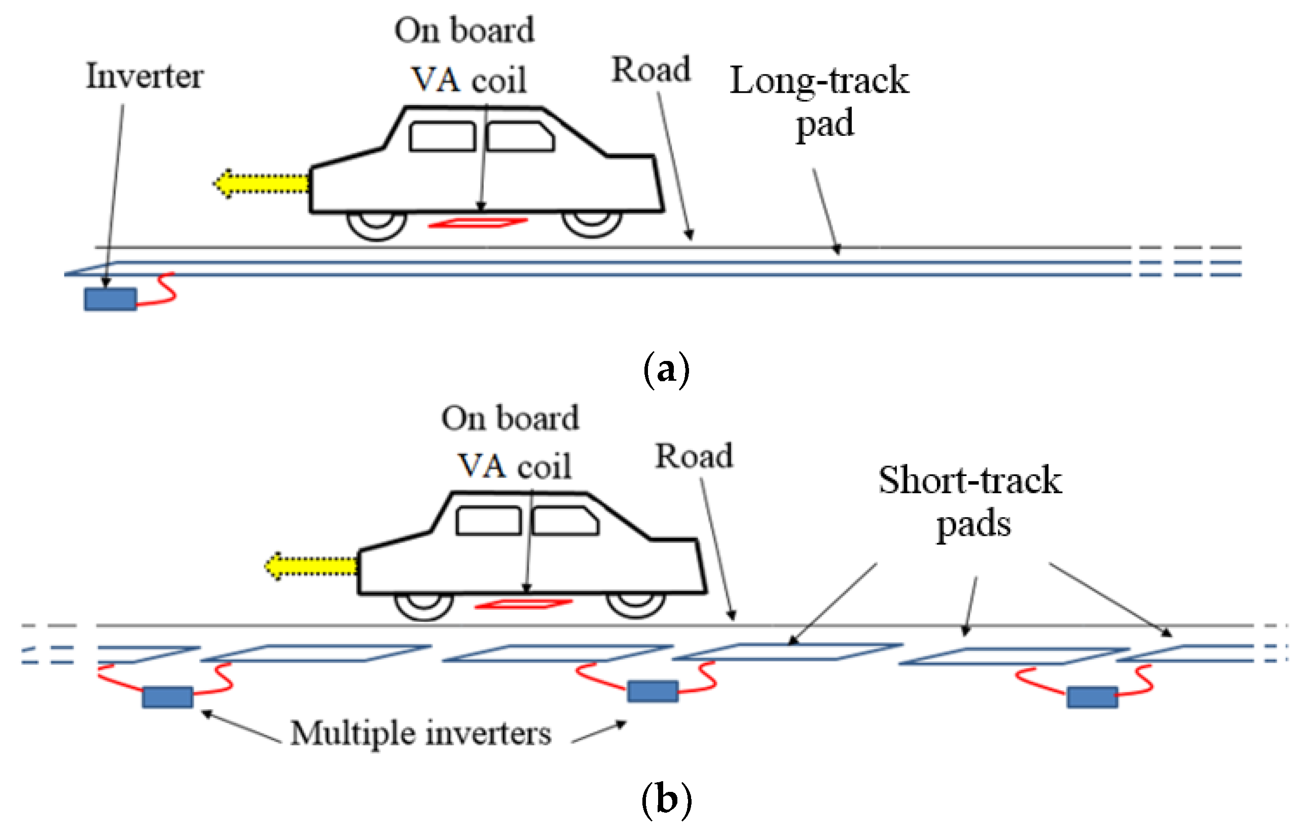
There are two main kinds of transmitter coils: (i) long-track pads that are quite similar to excitation rails; and (ii) multiple short-track pads that are quite similar to a series of relatively small primary coils studded on the road. The two solutions are schematically shown in Figure 2. The first architecture is better for EVs as they have fairly uniform excitation during their motion, but it is not very energy efficient, and the electromagnetic pollution in the surrounding environment is quite significant. The second architecture is more complex and the vehicle has different excitations during motion, but it is more efficient, and electromagnetic pollution is limited as the short track pads are energized one at a time only when an electric vehicle is just above a pad. The maximization of the efficiency and the reduction in the electromagnetic field (EMF) safety problem today render this solution the most promising but also the most complex. However, there are some important points that must be considered when adopting this configuration. First, the size of the GA coil is a critical parameter, as a shorter GA coil allows for high levels of efficiency, but the vehicle can only be powered for a short distance comparable to the length of the coil. Conversely, a longer coil allows for high transmission coverage but with reduced efficiency due to high magnetic flux leakage. In addition to the dimension of the single GA coil, another critical aspect is the separation between adjacent GA coils along the road (x-axis). In order to operate the system in optimal conditions, the GA coil only switches on when the VA coil is sufficiently aligned with the GA coil itself. Thus, in the space between two adjacent GA coils, the VA coil is not energized. In order to avoid this problem, the GA coils should be very close together or even overlapped, with a significant increase in the number of transmitting coils along the road. Thus, typically, a trade-off is calculated between the maximum number of GA coils and the space in which the VA coils are not energized.
However, the discontinuity of the power supply for the EV results in several problems: the overall charging time is increased, the battery life is reduced since the charge is not constant but with many peaks due to the transition of the coils, and, finally, the fast transition between coils gives rise to current transients that can produce electromagnetic interference (EMI) in the vehicle, harmonics in the main grid and magnetic fields in the environment.
3.2. Proposed Architecture
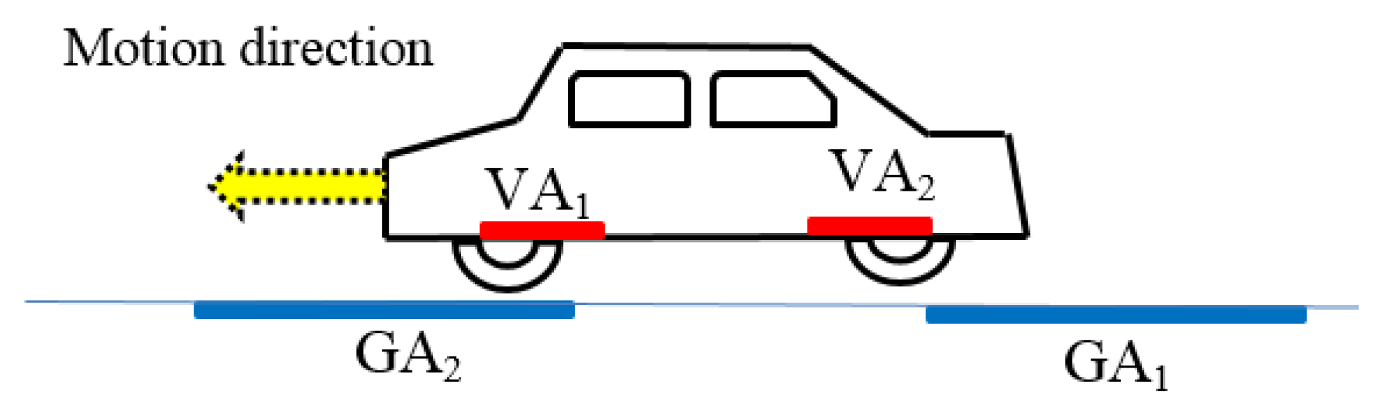
The proposed architecture is based on the new idea to equip the EV with two independent receiver coils named VA1 and VA2 and multiple short-track pads for the GA, as shown in Figure 3. An EV equipped with the proposed two-coil system moves on an electrified road with multiple short-track pads (GA1, GA2,…, coils) embedded in the road pavement. In the following discussion, the proposed architecture and the operational principle is explained; then, the system design is proposed.
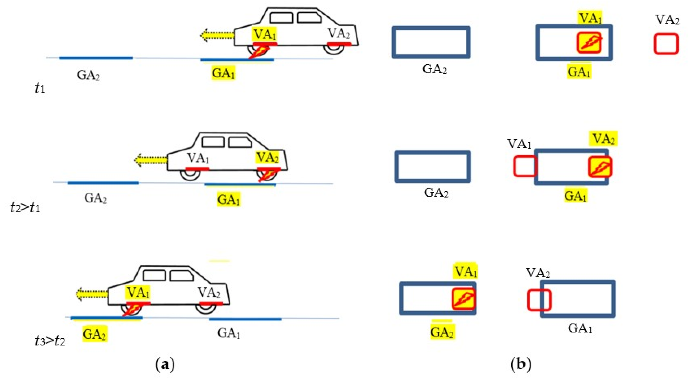
A sketch of three different positions for the moving vehicle along the road is shown in Figure 4. In Sequence 1 (corresponding at time instant t1), the GA1 is activated to wirelessly transfer energy to the VA1. When the coupling between GA1 and VA1 becomes too low due to the movement of the EV and the efficiency drops below a predetermined level, VA1 is disconnected, and VA2 is activated as receiver, as shown in Sequence 2 at time instant t2 > t1. This condition is maintained until the coupling between GA1 and VA2 falls below the predetermined level. At this time GA1 is deactivated, and the next GA2 coil is activated. At the same time VA2 is disconnected, and VA1 is again activated as receiver, as shown in Sequence 3 at time instant t3 > t2. Then, the procedure is repeated, as described above. Ideally neglecting the activation time, with this solution, the power supply to the EV is almost continuous, since one of the two VA coils is always powered by the GA coils with short-track architecture.
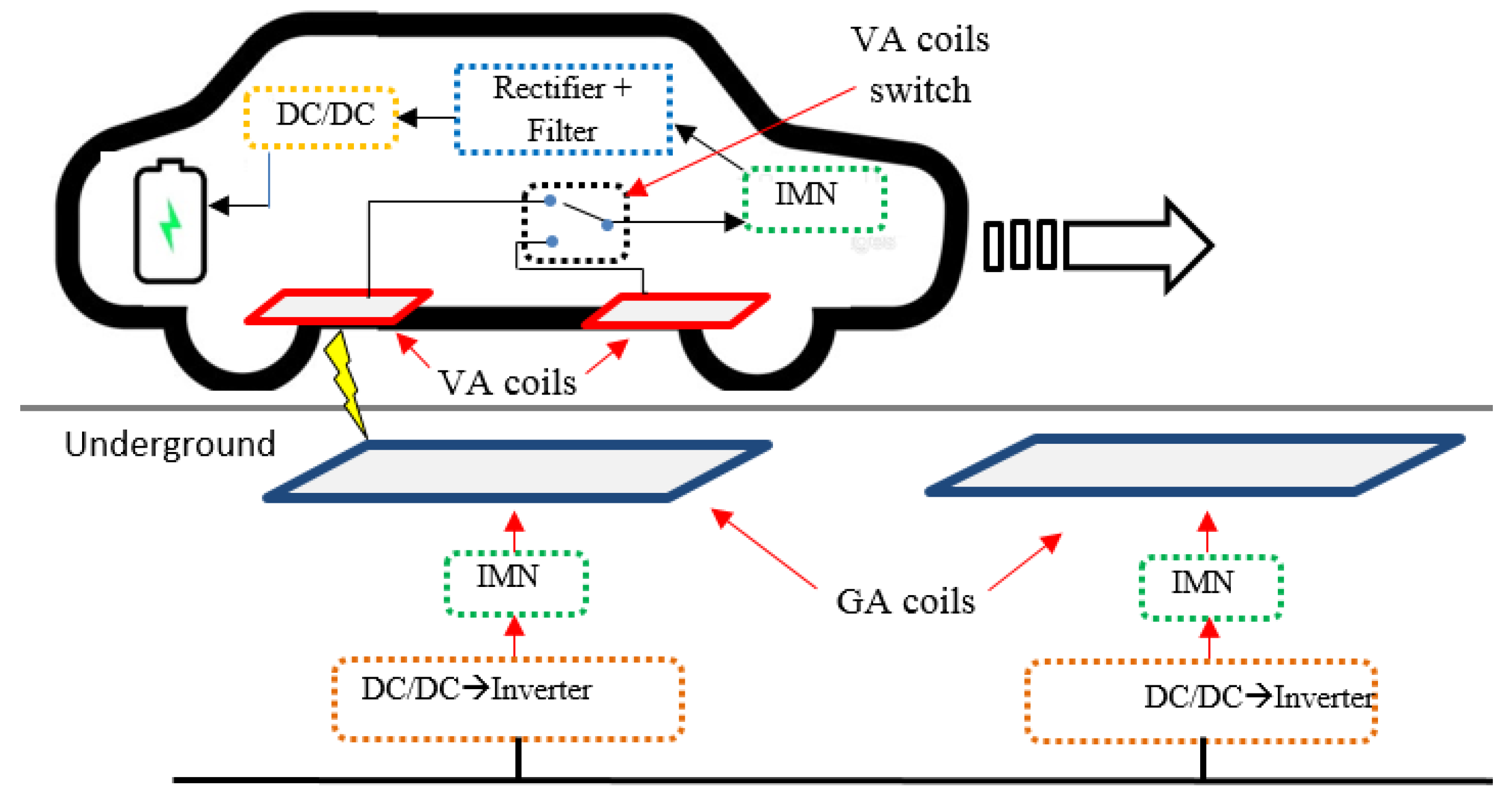
A typical electrical configuration for short track configuration is shown in Figure 5. On the GA side, each transmitter coil is powered at high frequency by an independent inverter and compensated by an impedance matching network (IMN) connected to the main grid by a bus (often in DC but can also be in AC at power frequency) by means of some power electronic devices.
The two VA coils are installed on the vehicle underbody and connected to a single IMN via a switch to select the most suitable VA coil to be activated. When one VA coil is used for energy transfer, the other is in open-end condition; thus, no current flows through it. The switch will operate at a lower frequency than the resonance frequency of the WPT system. Considering a cruising speed of 15 m/s = 54 km/h for the EV and considering that the switch is activated approximately every 1 m, the frequency of the switch is 15 Hz; thus, it can be easily made by using electronic switches such as SCR or TRIAC with extremely low losses.
4. Applications
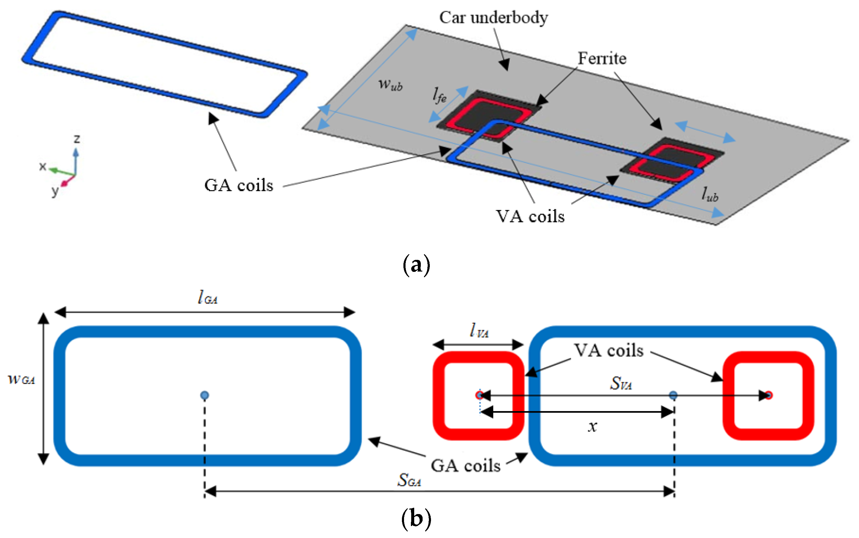
The proposed system is applied to realize a DWPT system working at the resonant frequency of 85 kHz with a nominal power of 7.7 kW for each VA in the electrified road section. The considered system is composed of multiple transmitting GA coils and two receiving VA coils installed under the vehicle body. The two VA coils have square shapes with exterior side lengths of lVA = 50 cm. A square ferrite layer with side wfe = 50 cm and thickness tfe = 8 mm [19] is interposed between the copper VA coil and the metallic body of the EV to mitigate the eddy currents in the conductive chassis. The GA coils have rectangular shapes with a width of wGA = 85 cm to ensure an adequate tolerance with respect to possible lateral misalignment of the coupled coils. The length of the GA coil lGA, the separation SGA between adjacent GA coils, and the separation SVA between the two VA coils are assumed to be the design variables that need to be optimized. To keep costs low, no conductive shields or magnetic materials are used in GA coils.
Magnetic field analysis is based on the solution of the MQS equations by COMSOL [18]. In order to simplify the configuration under study, the metallic body of the vehicle has been modelled by only its underbody, i.e., an aluminum plane with a dimension of lv = 350 cm and wv = 165 cm. The multi-turn copper coils are suitably modelled in the computational domain by considering the ferrite layers of the two VA coils. The road pavement and any other parts of the EV are neglected in the magnetic field calculation. The simplified configuration adopted for the magnetic field analysis is shown in Figure 6.
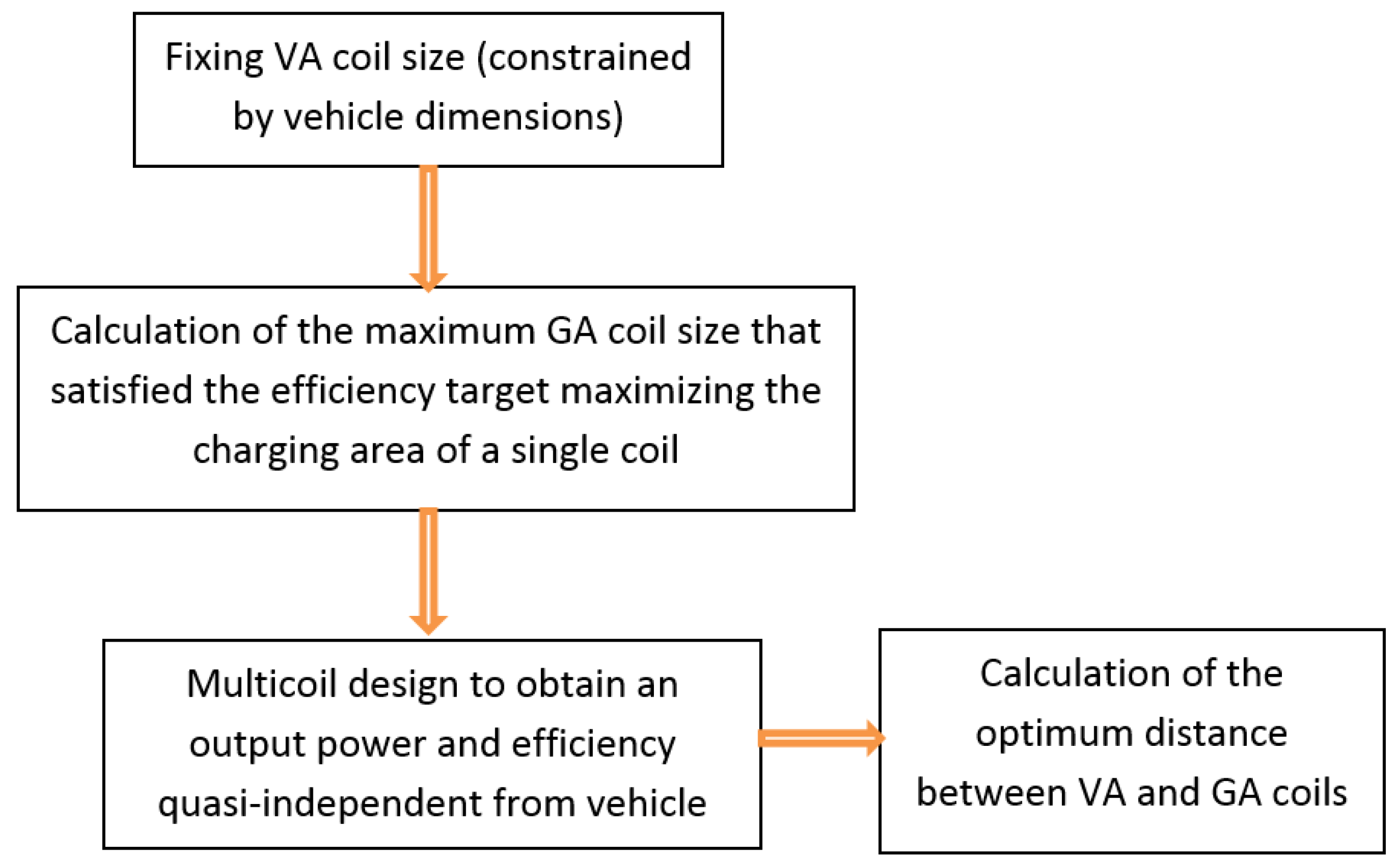
The proposed design flow is illustrated in Figure 7. As a first step, the size of the VA coil is fixed depending on car specifications and weight constraints. Then, a field analysis is carried out in order to find the best tradeoff between the GA coil length and electrical efficiency. A longer GA coil allows the use of fewer coils in the electrified road section but with an increase in magnetic flux leakage with a consequent reduction in efficiency. Finally, the optimum size of the GA coils is calculated to ensure nearly constant output power and efficiency when the vehicle is in motion.
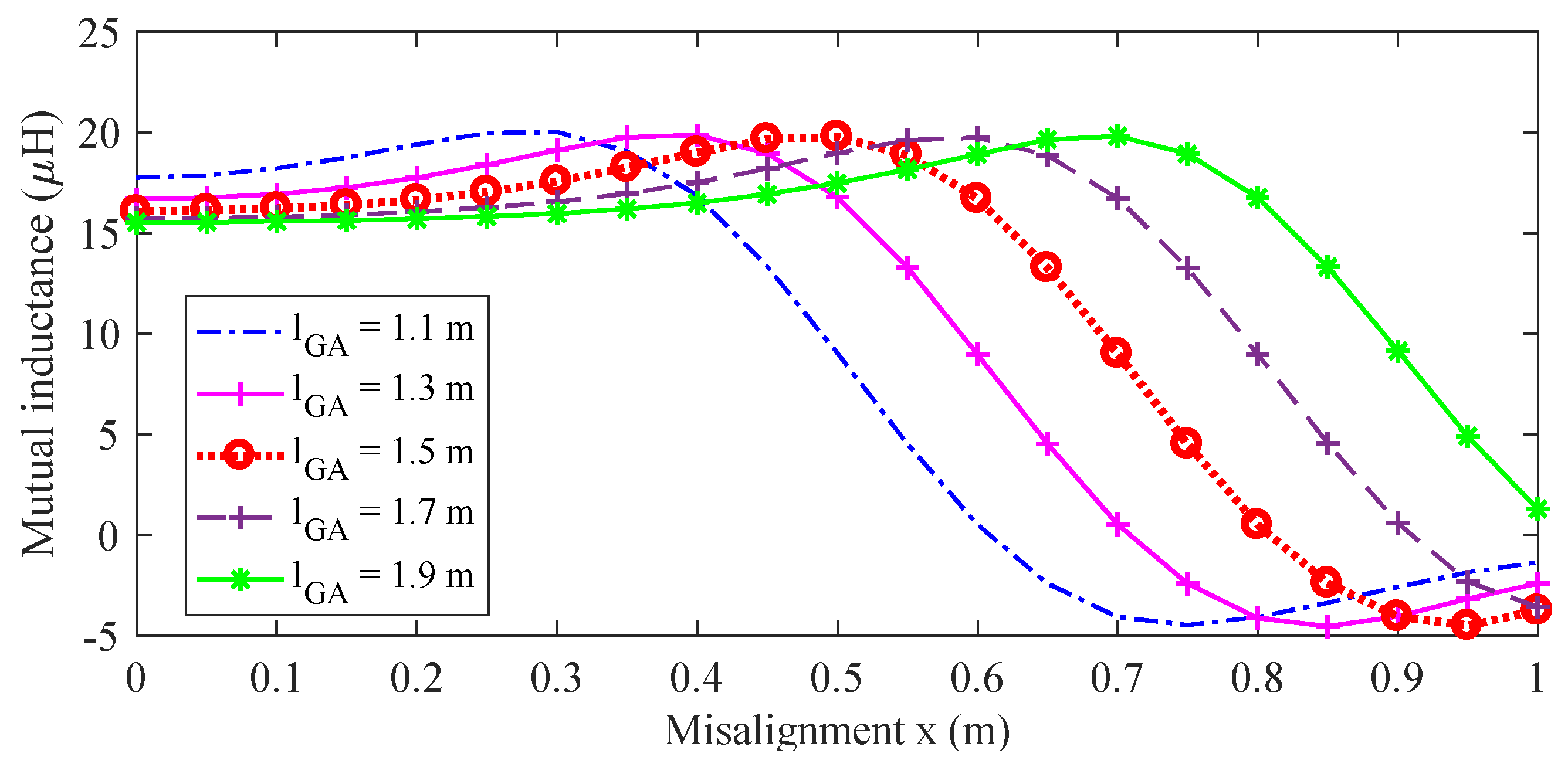
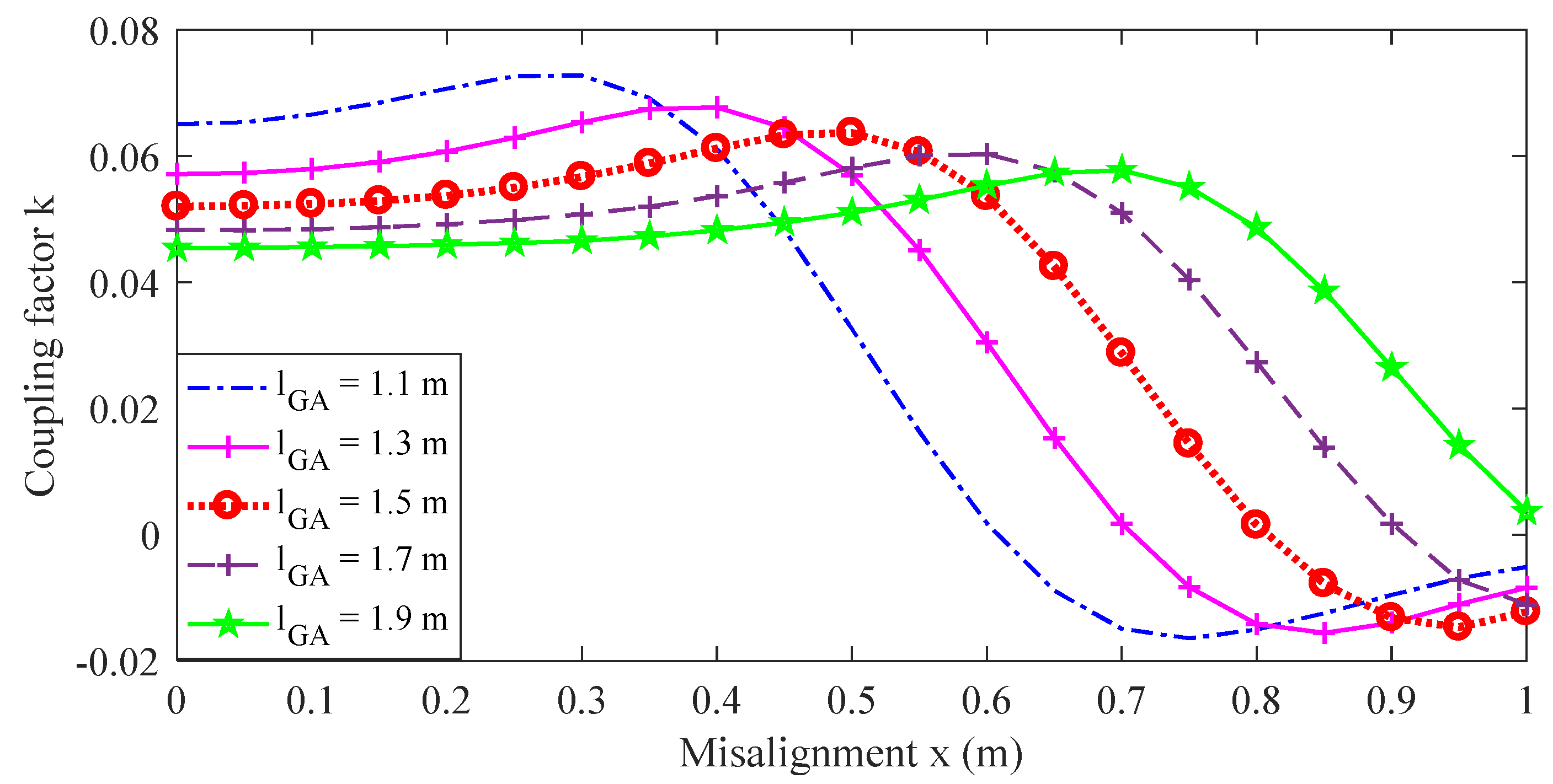
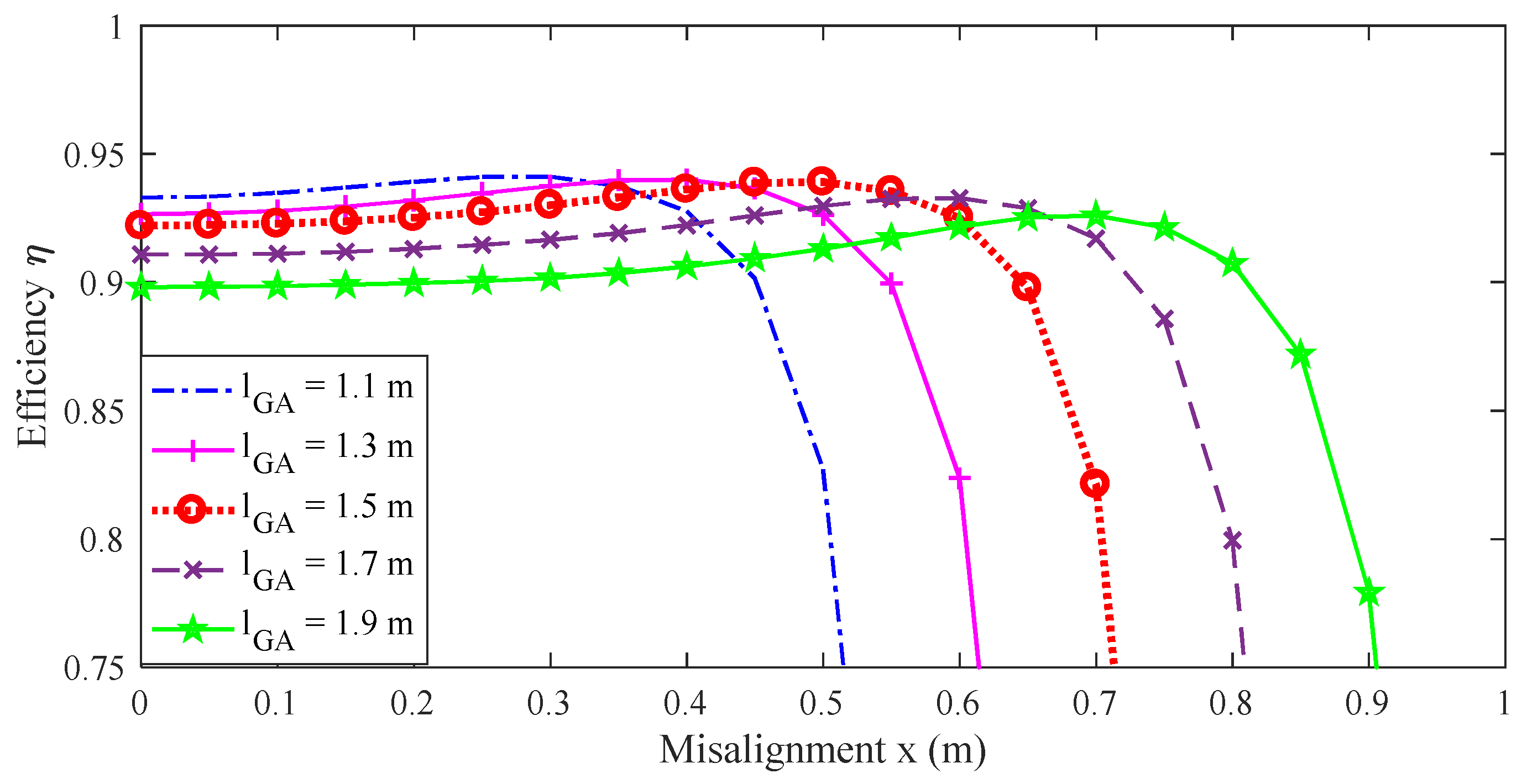
First, the self-inductances LGA and LVA are numerically calculated by (5)–(6) assuming a fixed number of turns for GA and VA coils set at NGA = 8 and NVA = 16, respectively, but also by assuming the length lGA of the GA coil variable. The values calculated for LGA and LVA for different GA coil lengths are reported in Table 1. Then, the mutual inductance M = M(x) is calculated by (9) for several GA coil lengths lGA and for several positions x of the VA coil center in order to simulate a moving vehicle. The behavior of the mutual inductance M = M(x) obtained by interpolation is shown in Figure 8. The coupling factor k = k(x) between GA and VA coil, calculated by (10), is shown in Figure 9. As observed, the variation of k is slightly higher than M due to the increase in GA coil self-inductance for larger GA coils. The position starts from the perfectly aligned coils (x = 0) up to a distance from the coil centers along the road direction equal to x = 1 m. The efficiency behavior η = η(x), calculated when considering SS compensation and the load modeled as a simple resistor RL = 10 Ω, is shown in Figure 10. The resistor RL is dimensioned to reproduce a load power of 7.7 kW at a voltage level of V2 = 280 V.
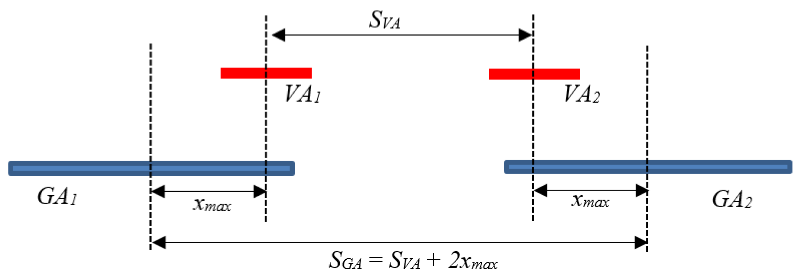
Considering a minimum target efficiency of ηmin = 92%, the maximum GA coil length is lGA = 150 cm; thus, this size is selected for the considered application. With this configuration, the efficiency η is good for coil separations (i.e., misalignment between GA and VA coil centers) up to xmax = 65 cm, as shown in Figure 10. Considering also the negative misalignment (thus, all the coils), we can find the optimum distance SVA between two receiving VA coils, which is, therefore, fixed to SVA = 2xmax = 130 cm. Likewise, the separation SGA between adjacent GA coils is calculated in order to ensure that when the second VA coil exceeds the maximum admissible misalignment, the first VA coil is activated with a misalignment x ≤ xmax. The separation SGA can be calculated as follows.
For the considered case, the optimum distance is found to be at SGA = 260 cm. A sketch of the configuration is reported in Figure 11.
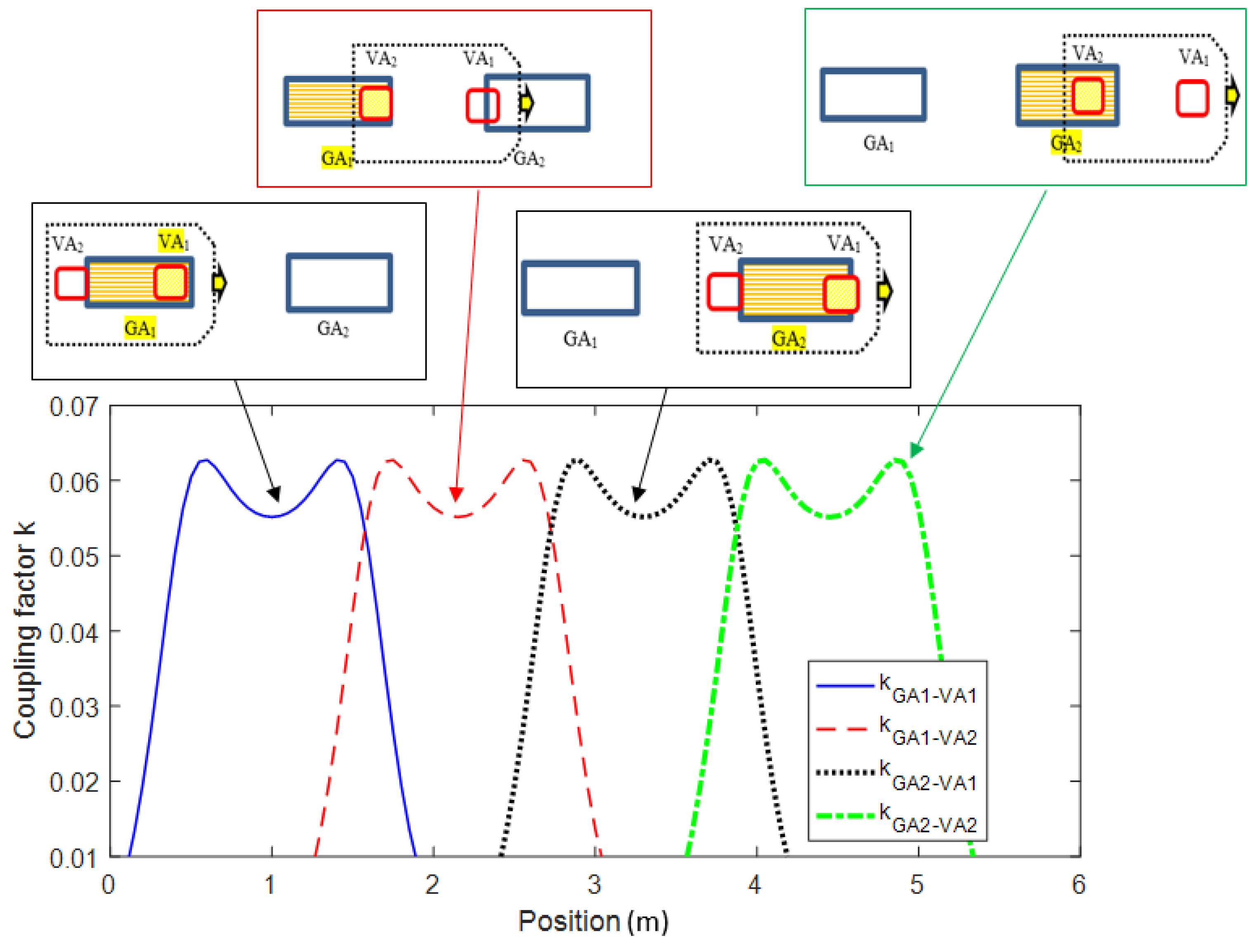
In order to understand the proposed configuration well, the coupling factor of the complete system is simulated by considering a road with several coils and an electric vehicle in motion. The coupling factor is calculated by considering the two proposed VA coils and a pair of GA coils. As observed from the results shown in Figure 12, the calculation of the optimal separation distance between both the GA and VA coils ensures a good coupling factor for all vehicle positions.
Then, the performance of the complete system is calculated. The switching transition between the transmitter and receiver coil is assumed to be instantaneous. This approximation is valid since the transient of the electronic switch is very fast and of the order of nanoseconds; thus, it is negligible compared to the time variation of the coupling factor/mutual inductance that depends on the speed of the vehicle.
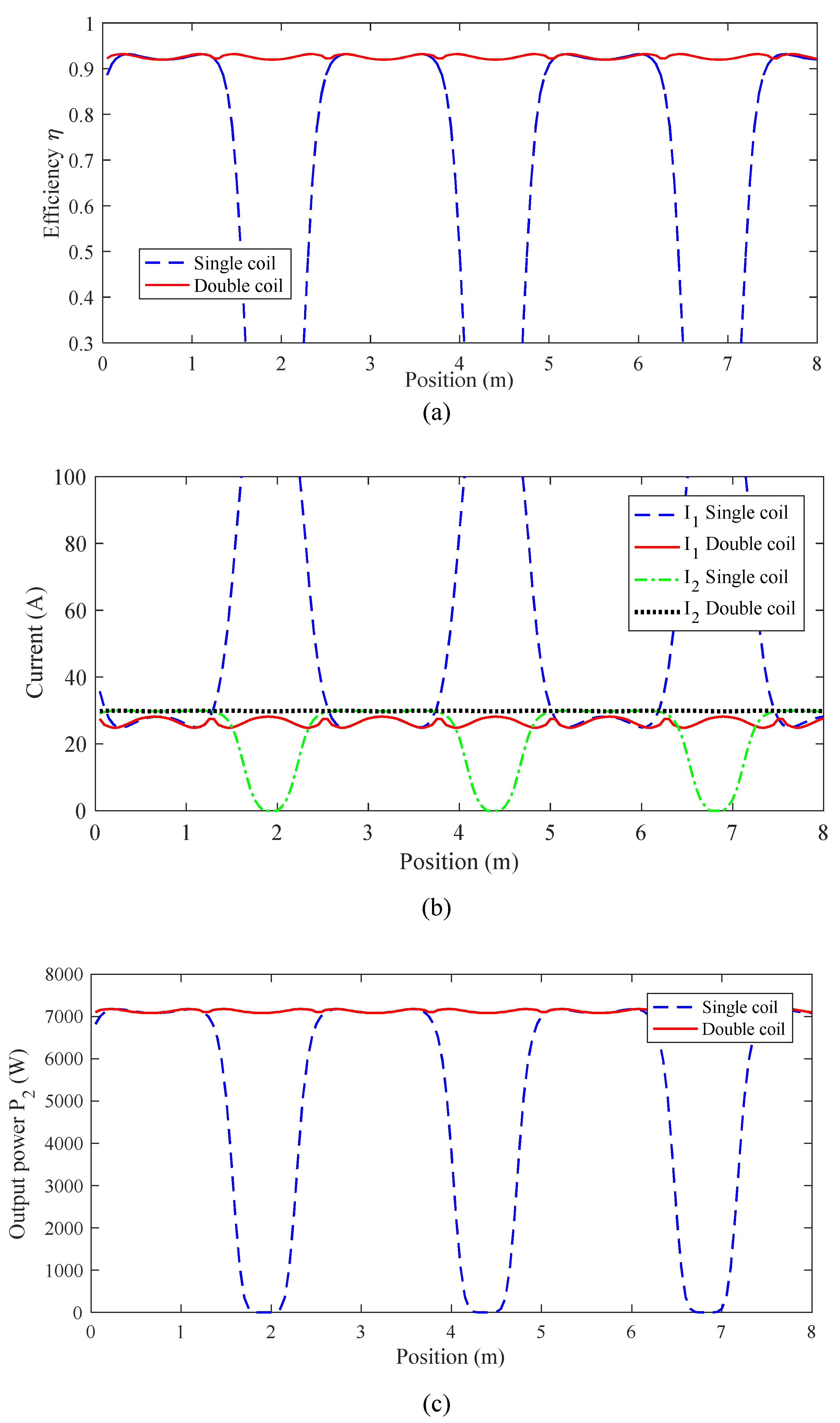
The system performances in terms of transferred power, efficiency, and coil currents are evaluated by considering a road length of 8 m covered by about four GA coils. In this numerical test, the input power is kept fixed at P1 = 7.7 kW. The obtained results are compared with a traditional system composed by a single VA coil in terms of efficiency η, coil currents IVA and IGA, and output power P2 vs. the position of the EV along the electrified road, as shown in Figure 13. The results demonstrated as the efficiency of the system and the transferred power are very high for all positions of the vehicle when assuming the solution based on two independent VA coils. The results obtained are very promising as they clearly demonstrate that the traditional configuration using a single VA coil exhibits large variations in current and power during the EV movement resulting in many power holes and over currents in the transmitter coil. On the contrary, by the proposed solution based on two independent VA coils, the power delivered to the EV is almost constant. We calculated the variation γ of the real power P2 as follows:
where Pmax is the peak value, and Pav is the average value of P2. We found γ = 2.8% for the proposed configuration. This excellent value is very useful for applications as it allows the battery of the electric vehicle to be optimally recharged and also reduces transients and electromagnetic interference. Note that the simultaneous use of both VA coils would not result in an improvement in system performance because only one pair of GA and VA coils at a time has a good coupling factor while the other VA coil does not have a good coupling factor. With the proposed coils design and arrangement, when one of the VA coils is operating in the working region of length SVA = 130 cm, the other VA has a low coupling factor because it is out of the working region. As observed in Figure 8 and Figure 9, out of the working region, the coupling factor and the efficiency drops very fast; thus, it is not convenient to use a second VA coil in this condition. The results obtained show how, with the proposed solution, it is possible to significantly mitigate power instability when the vehicle is in motion, solving one of the main problems of DWPT systems. The logic that can be used for the switching process of the transmitting coils is not reported for the sake of brevity; however, it is the same logic adopted for the traditional dynamic configuration that can be based on both sensors (optic, infrared, etc.) or on the assessment of coil impedance [20]. A very efficient solution for the activation of the primary coil is described in [21] where the real time calculation of input impedance is adopted for activating the GA coil only when a VA coil is detected. Similar techniques can be used for the selection of the receiving coil. In this case the decision on which coil should be activated is based on the real time calculation of efficiency. The calculation of the efficiency is made by the control unit and the communication channel between onboard electronics and ground units [21].
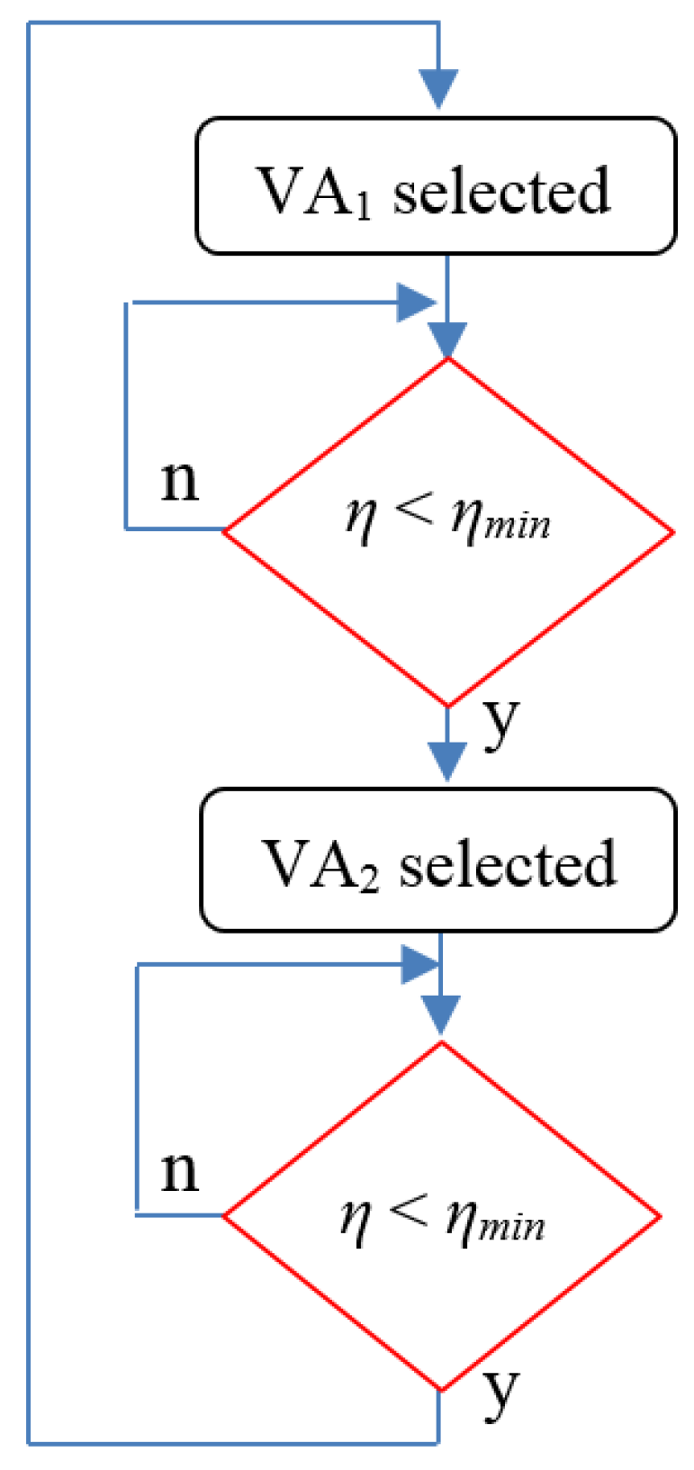
The flowchart of the charging coil selection is reported in Figure 14. As a starting condition, VA1 is selected as receiving coil (considering forward drive direction, it will be the first coil that receives energy). VA1 is used until the efficiency drops below a fixed value of efficiency (ηmin). When this occurs, the receiving unit is switched to VA2, and it is maintained until the efficiency drops again under ηmin; then, the receiving unit is switched again to VA1. This procedure is repeated and permits obtaining the power profile reported in previous figures.
5. Conclusions
An innovative configuration for a DWPT system based on a new receiver architecture based on two independent VA coils mounted in the EV underbody is presented. The two coils operate one at a time depending on the EV position along the electrified road. The selection of the best VA coil to be activated is based on the maximization of the inductive coupling with the transmitter coils. The proposed system is presented and optimized for an EV absorbing 7.7 kW at 85 kHz. Finally, several numerical simulations were carried out by comparing the proposed configuration based on two independent VA coils with the traditional configuration considering a single VA coil. The results obtained show how the proposed system is much more suitable for powering an EV with high efficiency for any position of the vehicle on the electrified road. We found “almost” stable power delivered to the EV with very little variation (γ = 2.8%) and with no holes. This power architecture is, therefore, optimal for recharging batteries of EVs in motion on an electrified road with short-track pads. The main advantages of the proposed solution for pick-up coil design are mainly two: the first is the reduction in costs for road infrastructure and the second is the stabilization of charging power, which improves battery life with a reduction in charging time.
Author Contributions
T.C., S.C., F.M. and M.F. conceived, planned the experiments and carried out the simulations. All authors provided critical feedback, improved the final design, analyzed the data and wrote the paper. All authors have read and agreed to the published version of the manuscript.
Funding
This research was funded by the University of L’Aquila, RIA Project, 2018.
Data Availability Statement
Not applicable.
Conflicts of Interest
The funding sponsors had no role in the design of the study; in the collection, analyses, or interpretation of data; in the writing of the manuscript; and in the decision to publish the results.
References
- Covic, G.A.; Boys, J.T. Inductive power transfer. Proc. IEEE 2013, 101, 1276–1289. [Google Scholar] [CrossRef]
- Shinohara, N. Power without wires. IEEE Microw. Mag. 2011, 11, 64–73. [Google Scholar] [CrossRef]
- Wang, C.-S.; Covic, G.A.; Stielau, O.H. Power Transfer Capability and Bifurcation Phenomena of Loosely Coupled Inductive Power Transfer Systems. Trans. Ind. Electron. 2004, 51, 148–157. [Google Scholar] [CrossRef]
- Ahmad, A.; Alam, M.S.; Chabaan, R.A. Comprehensive Review of Wireless Charging Technologies for Electric Vehicles. Trans. Transport. Electrific. 2018, 4, 38–63. [Google Scholar] [CrossRef]
- De Santis, V.; Campi, T.; Cruciani, S.; Laakso, I.; Feliziani, M. Assessment of the Induced Electric Fields in a Carbon-Fiber Electrical Vehicle Equipped with a Wireless Power Transfer System. Energies 2018, 11, 684. [Google Scholar] [CrossRef] [Green Version]
- Cruciani, S.; Campi, T.; Maradei, F.; Feliziani, M. Active shielding design for wireless power transfer systems. IEEE Trans. Electromag. Compat. 2019, 61, 1953–1960. [Google Scholar] [CrossRef]
- Campi, T.; Cruciani, S.; Maradei, F.; Feliziani, M. Magnetic Field during Wireless Charging in an Electric Vehicle According to Standard SAE J2954. Energies 2019, 12, 1795. [Google Scholar] [CrossRef] [Green Version]
- Laporte, S.; Coquery, G.; Deniau, V.; De Bernardinis, A.; Hautière, N. Dynamic wireless power transfer charging infrastructure for future evs: From experimental track to real circulated roads demonstrations. World Electr. Veh. J. 2019, 10, 84. [Google Scholar] [CrossRef] [Green Version]
- Buja, G.; Rim, C.T.; Mi, C.C. Dynamic Charging of Electric Vehicles by Wireless Power Transfer. IEEE Trans. Ind. Electron. 2016, 63, 6530–6532. [Google Scholar] [CrossRef]
- Cruciani, S.; Campi, T.; Maradei, F.; Feliziani, M. Active Shielding Applied to an Electrified Road in a Dynamic Wireless Power Transfer (WPT) System. Energies 2020, 13, 2522. [Google Scholar] [CrossRef]
- Lu, F.; Zhang, H.; Hofmann, H.; Mi, C.C. A Dynamic Charging System with Reduced Output Power Pulsation for Electric Vehicles. IEEE Trans. Ind. Electron. 2016, 63, 6580–6590. [Google Scholar] [CrossRef]
- Xiang, L.; Li, X.; Tian, J.; Tian, Y. A Crossed DD Geometry and Its Double-Coil Excitation Method for Electric Vehicle Dynamic Wireless Charging Systems. IEEE Access 2018, 6, 45120–45128. [Google Scholar] [CrossRef]
- Song, B.; Dong, S.; Li, Y.; Cui, S. A Dual-Layer Receiver with a Low Aspect Ratio and a Reduced Output Fluctuation for EV Dynamic Wireless Charging. IEEE Trans. Power Electron. 2020, 35, 10338–10351. [Google Scholar] [CrossRef]
- Campi, T.; Cruciani, S.; Maradei, F.; Feliziani, M. Near-Field Reduction in a Wireless Power Transfer System Using LCC Compensation. IEEE Trans. Electromagn. Compat. 2016, 59, 686–694. [Google Scholar] [CrossRef]
- COMSOL. Multiphysics. Available online: https://www.comsol.com/ (accessed on 10 June 2021).
- Feliziani, M.; Cruciani, S.; Campi, T.; Maradei, F. Artificial Material Single Layer to Model the Field Penetration Through Thin Shields in Finite-Elements Analysis. IEEE Trans. Microw. Theory Tech. 2018, 66, 56–63. [Google Scholar] [CrossRef]
- Feliziani, M.; Maradei, F. Edge element analysis of complex configurations in presence of shields. IEEE Trans. Magn. 1997, 33, 1548–1551. [Google Scholar] [CrossRef]
- Feliziani, M.; Maradei, F. Fast computation of quasi-static magnetic fields around nonperfectly conductive shields. IEEE Trans. Magn. 1998, 34, 2795–2798. [Google Scholar] [CrossRef]
- SAE TIR J2954, Wireless Power Transfer for Light-Duty Plug-In Electric Vehicles and Alignment Methodology. Available online: https://www.sae.org/standards/content/j2954_202010/ (accessed on 12 May 2020).
- Liang, C.; Zhang, Y.; Li, Z.; Yuan, F.; Yang, G.; Song, K. Coil Positioning for Wireless Power Transfer System of Automatic Guided Vehicle Based on Magnetic Sensing. Sensors 2020, 20, 5304. [Google Scholar] [CrossRef] [PubMed]
- Fabric European Project. Available online: http://www.fabric-project.eu/www.fabric-project.eu/index.html (accessed on 20 August 2021).
Figure 1.
Equivalent simplified circuit of a WPT system with SS compensation.

Figure 2.
DWPT coil architecture: Long-track pad (a) and multiple short-track pads (b).

Figure 3.
Proposed architecture.

Figure 4.
Sketch of three different sequences at different times of the proposed charging solution during EV movement. (a) Lateral view. (b) Top view (GA coil depicted in blue and VA coil in red, red lightning means coil activation).
Figure 4.
Sketch of three different sequences at different times of the proposed charging solution during EV movement. (a) Lateral view. (b) Top view (GA coil depicted in blue and VA coil in red, red lightning means coil activation).

Figure 5.
Working flow of the proposed architecture.

Figure 6.
Configuration used in FEM simulation including multiple GA coils on the road and double VA coil in the underbody of the vehicle (a). Top view of GA and VA coils (b).
Figure 6.
Configuration used in FEM simulation including multiple GA coils on the road and double VA coil in the underbody of the vehicle (a). Top view of GA and VA coils (b).

Figure 7.
Proposed design workflow.

Figure 8.
Mutual inductance M = M(x) vs. coil separation along road axis for different lengths lGA of the GA coil.
Figure 8.
Mutual inductance M = M(x) vs. coil separation along road axis for different lengths lGA of the GA coil.

Figure 9.
Coupling factor k = k(x) vs. coil separation along road axis for different lengths lGA of the GA coil.
Figure 9.
Coupling factor k = k(x) vs. coil separation along road axis for different lengths lGA of the GA coil.

Figure 10.
Efficiency η vs. coil separation x along road axis for different lengths lGA of the GA coil.
Figure 10.
Efficiency η vs. coil separation x along road axis for different lengths lGA of the GA coil.

Figure 11.
Sketch of the final configuration.

Figure 12.
Coupling factor vs. vehicle position.

Figure 13.
Comparison of system efficiency η (a), coil currents I1 and I2 (b), and output power P2 (c) between standard single VA coil configuration and proposed two independent VA coils.
Figure 13.
Comparison of system efficiency η (a), coil currents I1 and I2 (b), and output power P2 (c) between standard single VA coil configuration and proposed two independent VA coils.

Figure 14.
Flowchart of the VA coil selection.


Table 1.
Self-inductances LGA and LVA for different lengths lGA of the GA coil.
| lGA (m) | LGA (μH) | LVA (μH) |
|---|---|---|
| 1.1 | 338.2 | 218.7 |
| 1.3 | 386.5 | 218.9 |
| 1.5 | 435.7 | 218.6 |
| 1.7 | 483.1 | 218.5 |
| 1.9 | 531.5 | 218.7 |
Publisher’s Note: MDPI stays neutral with regard to jurisdictional claims in published maps and institutional affiliations. |
© 2021 by the authors. Licensee MDPI, Basel, Switzerland. This article is an open access article distributed under the terms and conditions of the Creative Commons Attribution (CC BY) license (https://creativecommons.org/licenses/by/4.0/).
Share and Cite
MDPI and ACS Style
Campi, T.; Cruciani, S.; Maradei, F.; Feliziani, M. Two-Coil Receiver for Electrical Vehicles in Dynamic Wireless Power Transfer. Energies 2021, 14, 7790. https://0-doi-org.brum.beds.ac.uk/10.3390/en14227790
AMA Style
Campi T, Cruciani S, Maradei F, Feliziani M. Two-Coil Receiver for Electrical Vehicles in Dynamic Wireless Power Transfer. Energies. 2021; 14(22):7790. https://0-doi-org.brum.beds.ac.uk/10.3390/en14227790
Chicago/Turabian StyleCampi, Tommaso, Silvano Cruciani, Francesca Maradei, and Mauro Feliziani. 2021. "Two-Coil Receiver for Electrical Vehicles in Dynamic Wireless Power Transfer" Energies 14, no. 22: 7790. https://0-doi-org.brum.beds.ac.uk/10.3390/en14227790
Note that from the first issue of 2016, this journal uses article numbers instead of page numbers. See further details here.