Article

Low-Cost Air-Cooling System Optimization on Battery Pack of Electric Vehicle

by
Robby Dwianto Widyantara
1,
Muhammad Adnan Naufal
1,
Poetro Lebdo Sambegoro
1,
Ignatius Pulung Nurprasetio
1,
Farid Triawan
2,
Djati Wibowo Djamari
2,
Asep Bayu Dani Nandiyanto
3,
Bentang Arief Budiman
1,* and
Muhammad Aziz
4,*
1
Faculty of Mechanical and Aerospace Engineering, Institut Teknologi Bandung, Jl. Ganesha No. 10, Bandung 40132, Indonesia
2
Department of Mechanical Engineering, Faculty of Engineering and Technology, Sampoerna University, Jl. Raya Pasar Minggu No. 16, Jakarta 12780, Indonesia
3
Departemen Kimia, Universitas Pendidikan Indonesia, Jl. Dr. Setiabudi No. 229, Bandung 40154, Indonesia
4
Institute of Industrial Science, The University of Tokyo, 4-6-1 Komaba, Meguro-ku, Tokyo 153-8505, Japan
*
Authors to whom correspondence should be addressed.
Submission received: 21 October 2021 / Revised: 22 November 2021 / Accepted: 22 November 2021 / Published: 28 November 2021
(This article belongs to the Special Issue Numerical Heat Transfer and Fluid Flow 2021)

Abstract

:
Temperature management for battery packs installed in electric vehicles is crucial to ensure that the battery works properly. For lithium-ion battery cells, the optimal operating temperature is in the range of 25 to 40 °C with a maximum temperature difference among battery cells of 5 °C. This work aimed to optimize lithium-ion battery packing design for electric vehicles to meet the optimal operating temperature using an air-cooling system by modifying the number of cooling fans and the inlet air temperature. A numerical model of 74 V and 2.31 kWh battery packing was simulated using the lattice Boltzmann method. The results showed that the temperature difference between the battery cells decreased with the increasing number of cooling fans; likewise, the mean temperature inside the battery pack decreased with the decreasing inlet air temperature. The optimization showed that the configuration of three cooling fans with 25 °C inlet air temperature gave the best performance with low power required. Even though the maximum temperature difference was still 15 °C, the configuration kept all battery cells inside the optimum temperature range. This finding is helpful to develop a standardized battery packing module and for engineers in designing low-cost battery packing for electric vehicles.

1. Introduction

In the last three decades, electric vehicles (EVs) have been developed rapidly and have brought a massive transformation in the automotive industry due to their low emission and energy-efficient advantages over internal combustion engine vehicles (ICEV) [1,2]. However, despite its rapid development, the current technology of EV still has several drawbacks compared to ICEV. One of the main disadvantages is the high battery cost, which is more than 40% of the total EV price [3]. This high cost is partly caused by the advanced technological implementation in the battery packing to assure high performance and high safety standards, such as complex cooling systems, massive structural packing protection, and advanced electrical system for energy management and control.
The batteries experience high charging and discharging rates during EV operation, increasing their surface temperature [4]. The frequency of charging and discharging also impacts battery degradation, decreasing the battery’s lifetime [5]. To realize the best performance and longest lifetime, the batteries need to be operated under the optimal temperature condition. This optimal temperature condition for a lithium-ion battery consists of two terms: (1) the optimal operating temperature range, which states the temperature range where a battery cell gives optimal charging and discharging rate while maintaining the longest life cycle; and (2) the maximum temperature difference, which states the maximum difference in temperature between each battery cells to one another to provide relatively uniform charging and discharging rates.
The optimal temperature for lithium-ion battery cells to operate is in the range of 25 to 40 °C, with a maximum temperature difference among battery cells of 5 °C [6]. Operating outside the optimal temperature range can decrease the battery’s performance significantly [7]. Moreover, safety issues like thermal runaway may arise when the battery operates in high-temperature conditions [8]. Temperature differences among battery cells may occur due to an inappropriate cooling system, especially when air cooling is applied. These differences may cause each battery cell to have different charging–discharging rates. Therefore, they are not beneficial because the battery management system (BMS) must work hard in balancing the state of charge (SOC) of the batteries, which can degrade its lifespan faster.
A battery thermal management system (BTMS) plays an essential role in maintaining the temperature of batteries at the optimal operating temperature [9]. An optimum BTMS can also reduce the workload of the BMS by lowering the temperature differences among battery cells. Therefore, various kinds of BTMS are applied and installed in the battery packing, such as air cooling [10], liquid cooling [11], heat pipe [12], and phase change materials (PCMs) [13]. Being a novel medium for BTMS and having high efficiency and stable performance in extreme conditions, PCMs have gained popularity in recent times. However, PCMs have the disadvantages of having low conductivity and needing to be regenerated after completely melted [14].
On the other hand, heat pipe systems do not suffer from these drawbacks, and they do not require an external power supply. They have high conductivity and efficiency in reducing battery temperature rise, but the equipment is complicated and not conducive to the practical applications of EV [15,16]. Another thermal management system, liquid-cooled BTMS, is also complex with its many supporting devices, like pumps, fans, and pipes, making it costly and vulnerable to the risk of leakage that may lead to a short circuit [17].
Another cooling method in BTMS is an air-cooling system. This system has a simple configuration, low initial and maintenance cost, simple integration, and it possesses no risk of leakage, making it more favorable in the market compared to the methods mentioned above. Moreover, air-cooling systems can significantly lower battery manufacturing costs, which directly reduces the EV price. However, despite its advantages, low heat transfer coefficient, uneven temperature distribution, and low efficiency are the main drawbacks of air-cooled BTMS [18,19]. To overcome the low heat transfer coefficient of air as the cooling medium, a hybrid system of BTMS was developed either by combining air-cooling with PCMs [20] or by integrating air-cooling with mini-channel liquid cooling [21]. These studies successfully lower the battery’s temperature, but on the other hand, increase the BTMS power consumption.
Adjusting the structure and flow configuration of the battery pack could also be beneficial to lower the temperature difference between battery cells and increase the efficiency of air-cooled BTMS. Several studies were conducted to achieve this result by optimizing the shape of battery pack [22,23]. Xu et al. [22] discovered that a horizontal battery pack with a double U-type duct could improve the heat dissipation performance of the air-cooling system in various conditions. Zhang et al. [23] minimized the temperature difference in battery packs for prismatic battery cells for Z-, U-, and I-types air-cooled BTMS by optimizing the widths of parallel cooling channels and divergence/convergence ducts. Other studies also have focused on improving the air-cooled BTMS by adding parts to the battery pack [24,25]. Mohammadian et al. [24] studied that thermal management of air-cooling systems of high-power lithium-ion batteries could be enhanced by implementing aluminum metal porous. Hong et al. [25] improved air-cooled BTMS performance in reducing temperature differences by adding a secondary vent. And some studies did both, optimizing the shape and adding parts to the battery pack. Jiaqiang et al. [26] improved the performance of the air-cooling strategy by locating the lateral inlet and outlet on different sides and utilizing the baffle plates. Other studies have tried to improve air-cooled BTMS performance by optimization. Liu et al. [27] performed manifold size optimization to improve J-type BTMS thermal performance under varying working conditions, resulting in the optimal configurations for each battery working condition. To achieve optimal performance for different battery working conditions, a valve control mechanism was needed to control the manifold size. Chen et al. [28] found that optimization of airflow parallel outlet position can improve the performance of J-type BTMS for prismatic battery cells; although, optimization for the airflow parallel inlet position is not as effective.
The studies mentioned above [22,23,24,25,26,27,28] may have successfully improved BTMS performance, but their practical implementation on EVs is still challenging, especially in reliability, energy density, and feasibility due to its complexity. Moreover, there has been no standard and design guideline regulating the battery packing until now, which leads to complex designs for battery packing. In addition, to improve the applicability, the optimization design should consider the air properties, number and position of cooling fans, spacing between cells, and other related factors [29]. These factors must be determined during the design process, together with maintaining lower manufacturing costs.
Despite the numerous studies conducted to improve the performance of air-cooling systems either by combining the air-cooling system with another type of cooling system or adjusting the structure and airflow configuration of the battery pack, not a lot have been done by optimizing the number of cooling fans and the inlet air temperature. By optimizing these parameters, this research aimed to develop a simple yet reliable air-cooling system that can simultaneously maintain high energy density by conditioning the battery temperature inside the optimal temperature condition while having low manufacturing cost.
Thermal analysis was necessary to investigate the effect of the number of cooling fans and inlet air temperature on the BTMS performance for the optimization. Some studies have performed thermal analysis for electric vehicle batteries using simulation. For example, Raharjo et al. [30] conducted a thermal analysis of modular battery by computational fluid dynamics (CFD) simulation to understand its thermal behavior, prevent overheating, and maintain battery life. Divakaran et al. [31] performed finite element simulation to analyze 18,650 lithium-ion batteries’ thermal behavior under two conditions: with and without cooling systems.
To understand the cooling phenomenon, the battery packing was built in a 3D numerical model and analyzed using CFD simulation based on the lattice Boltzmann method (LBM). The effects of the number of cooling fans and inlets on air velocity and temperature distribution inside the battery pack were revealed, and the simulation results from the LBM analysis were compared. The effects of the number of cooling fans and inlets along with the inlet air temperature on the performance of BTMS were then discussed thoroughly. Furthermore, an optimized cooling strategy for air-cooled BTMS based on the consideration of temperature distribution and power consumption was developed. The results of this study are significant to develop a standardized battery packing module and enrich the literature on electric vehicle battery pack optimization.

2. Numerical Model and Simulation

2.1. Heat Generation in Battery Cell
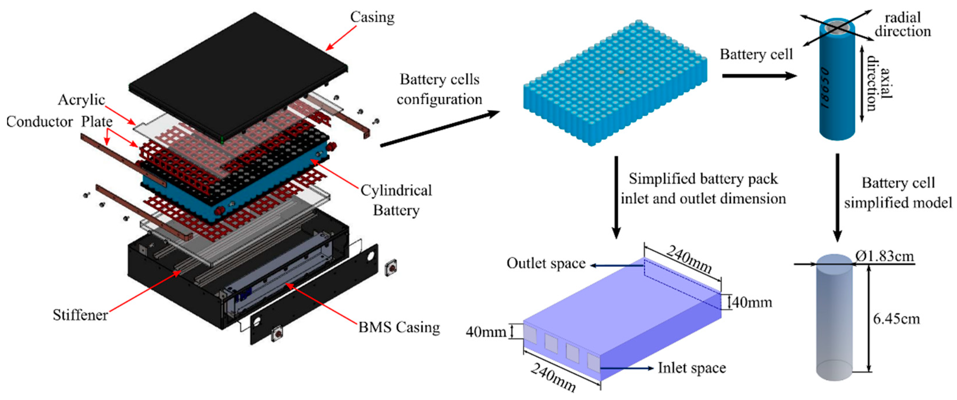
In battery packing, the battery cells generate heat during the charging and discharging processes. The initial temperature was set according to the ambient temperature. The heat generation of the lithium-ion battery module consisted of two primary sources: the irreversible heat caused by the Joule’s heating based on the internal resistance (Qirr) and the reversible heat inside the battery (Qrev). From these sources, the battery heat generation can be represented by Equation (1) [26].
Q = I 2 R e   I [ T d E d T ]
where I is the current flowing through the battery (A), Re is the internal resistance (Ω), T is the temperature (K), dE/dT is the entropy coefficient (V/K), and Q is the battery heat generating rate (W). Re and dE/dT are a function of battery temperature (T) and SOC as shown in Equations (2) and (3), respectively.
R e = ( 112 × S O C 3 0.203 × S O C 2 × T + 0.000737 × S O C × T 2 + 0.00000753 × T 3 + 301 × S O C 2 0.144 × S O C × T 0.0061 × T 2 188 × S O C + 1.28 × T + 23.6 ) × 10 3
d E d T = ( 0.342 + 0.979 × S O C 1.49 × S O C 2 + 0.741 × S O C 3 ) × 10 3
To model the battery in an extreme condition, we used a current of 2.6 A for 1 C discharge rate, battery temperature of 20 °C, SOC of 0.1, along with the parameters shown in Table 1. The parameters were under the assumption of operation in a tropical region with the already included ambient temperature. Based on Equations (1) to (3), the lower the SOC or the battery temperature, the higher the heat generated from the battery. SOC of 0.1 was the limit value used in the experiment by Jiaqiang et al. according to the recommendation of the battery manufacturer [26]. Meanwhile, the battery temperature of 20 °C was used as the low temperature in possible operating conditions in a tropical region with an average ambient temperature of 30 °C. The heat generation rate of the battery module was calculated with the result of 81.02 W. This value was used for the simulation input for battery cell heat generation.

2.2. System Design

The battery pack design in this study is shown in Figure 1. The interconnection of the battery cells developed within the battery pack created an electrical and mechanical connection, and the casing covered the mechanical requirements for the battery pack. The battery pack also consisted of stiffeners and acrylic to support the battery pack under static and dynamic loads transferred from an electric frame or chassis. The conductor plate was used to flow electricity from the battery to other electrical components and vice versa. The BMS, which could be an active or passive balancer, was placed inside the BMS casing. The inlet and outlet of the airflow were created on the lateral side of the battery pack casing to investigate the effect of forced convection by the cooling fan on the temperature distribution within the battery pack. The battery cells used in this battery pack were lithium nickel manganese cobalt oxide (NMC) 18,650 cylindrical batteries, and the specification is presented in Table 1. The 18,650 cylindrical battery type was employed due to its popularity in its application for electric vehicle battery. This module was suitable for electric trike and city cars. The electric trike, in particular, is currently being developed in our research facilities and has been presented in several studies, such as by Reksowardojo et al. [34].
The original geometry of the battery pack was complex, so it was difficult to configure the airflow within the battery pack iteratively with the Ansys Discovery Live software. This situation could also lead to continuous errors and long simulation time. To achieve the optimum results using the software, the battery pack was modeled as a simplified form without removing the components sensitive to the heat generation within the battery pack. The battery cells themselves consisted of layers of cathode, anode, separator, and current collector. Although these different layers had their thermal properties, the detailed structure of the cylindrical cell presented in Figure 1 had an insignificant impact on the thermal performance of the battery, according to many references [35,36]. Therefore, the battery parameters listed in Table 1 were utilized as the equivalent values representing a whole battery cell.
The simplified model of the battery pack was created in the form of 240 cells enclosed by a box, as shown in Figure 1. Each battery cell is represented as a cylinder with a diameter of 18.3 mm and a height of 64.5 mm. The offset between the 240 cylinders and the box was 1 mm on each surface. This close proximity was applied to ensure the designed battery pack had a high density and compact geometry as space and weight in EV are the main constraints to increase energy density [37]. The distance between the center of the two adjacent cylinders was 20 mm, and the gap between them was 1.7 mm. The pack would act as the fluid, and the inlet came from one lateral side and the outlet on the other.
Forced convection utilized in this system was carried out using a cooling fan. The available area for the cooling fan was 240 mm × 40 mm; therefore, the maximum dimension of the cooling fan was 40 mm × 40 mm. The selected cooling fan was a chip cooler AP0405MX-J70 from Adda Corp. with a rated power of 0.7 W and a maximum airflow of 4.7 CFM or 7.99 m3/h.
The effect of fluid flow within the battery pack on the temperature distribution was studied by conducting LBM-based transient CFD simulations. For the simulation, the airflow inlet and outlet were positioned at the lateral opposing end of the battery pack, while the other sides were set as the wall. Each inlet was accompanied by one cooling fan. For simplicity, from this point forth, the number of cooling fans and inlets will be called the number of inlets only, without mentioning the cooling fans. The number of inlets was varied into four configurations of 1-, 2-, 3-, and 4-inlets to investigate the effect of airflow configuration on temperature distribution inside the battery pack. Afterward, the inlet air temperature was varied by 20, 25, and 30 °C for each airflow configuration to investigate the effect of inlet air temperature on temperature distribution and to calculate the power required for each variation. Finally, the configuration with minimum temperature distribution and power consumption was chosen as the optimum cooling strategy.

2.3. Lattice Boltzmann Method

The simulation was conducted using LBM that discerned air at its mesoscopic scale. LBM has an advantage in its excellent numerical stability and can be solved efficiently on parallel computers [38]. Furthermore, due to its diffusive particle modeling, LBM could handle the simulation of complex topology [39]. In LBM, the motion of the air particles is modeled in a completely disordered direction and random manner whose velocities are distributed around the mean value. In this study, the structure is introduced as the Bhatnagar–Gross–Krook (BGK) (Equation (4)) model is discretized in the lattice unit of space x and time t [40].
f i ( x   +   e i Δ t , t   +   Δ t )     f i ( x , t )   =   Δ t 1 τ ( f i e q ( x , t )     f i ( x , t ) )   +   Δ t e i F k
where f i is the distribution function of air particles, Δ t is the lattice time step, Fk is the external force, ei is the discrete lattice velocity vector of a particle in a link, τ is the single relaxation time, f i e q is the local equilibrium distribution function, and i represents the air particle in specified lattice point.
The LBM simulation was conducted using ANSYS Discovery Live to generate instant results of the velocity and temperature distribution within the battery pack. The model used in the LBM simulation was created using ANSYS Space Claim that was integrated with ANSYS Discovery Live. The dimension of each inlet was 40 mm × 40 mm, and the outlet dimension was 240 mm × 40 mm. The volume of the fluid was then extracted from the inlet to the outlet that enclosed the cylinders. After this process, airflow from the inlet to the outlet could be seen in real-time or live. The flow velocity at the inlet was set to 1.4 m/s according to the cooling fan characteristics, and at the outlet, the relative pressure was set to 0 MPa. The ambient temperature was 30 °C according to the average ambient temperature for the tropical region where the BTMS was designed to be used. The air was assumed to be dry air having low thermal conductivity to represent the worst cooling condition. The thermal condition of the battery cells was set by adjusting the heat flow for each cylinder with the calculated heat generation rate of 0.338 W. The example of the model in ANSYS Discovery Live, consisting of battery cells and the volume of the fluid within the battery pack for four inlets, is shown in Figure 2.
The solution was created by assigning the inlet region and the outlet region enclosing the whole model. This region that enclosed the cylinders was extracted as the volume of fluid, which was the volume of air flowing. After the fluid volume was extracted, the velocity contour of the air flowing could be investigated from the maximum value or the small particles flowing within the battery packs. The number of particles flowing within the battery pack could be adjusted by setting the solution’s speed or fidelity, where high-speed results reduced the fidelity, and the high fidelity reduced the speed results. This fidelity was based on the distance between the lattice points. The high speeds could generate the temperature contour within seconds, albeit not very accurately, because when the high-speed result was chosen, fewer particles of air were flowing within the cells. In this simulation for the 3D geometry model, the setting was adjusted to have higher fidelity than the speed, so the contour of the temperature distribution would resemble the real condition more accurately. The simulation in this work was performed in two configurations. The former was varying the number of inlets into 1, 2, 3, and 4 inlets with a constant inlet air temperature of 30 °C to study the effect of airflow configuration on temperature distribution. The latter was varying both the number of inlets (1, 2, 3, and 4 inlets) and the inlet air temperature (20, 25, and 30 °C) to find the optimum cooling strategy for the air-cooled BTMS.

3. Results and Discussion

3.1. LBM Simulation Results

The effect of airflow configuration on temperature distribution within the battery pack was studied by varying the number of inlets and simulated using LBM-based CFD. A constant air inlet temperature of 30 °C was used to represent the average air temperature of the tropical region where the BTMS was intended to be used. The performance of air-cooled BTMS could be represented by the air velocity and the temperature inside the battery pack. The air velocity affected the convective heat transfer of the air and indicated the amount of air flowing and taking the heat generated by the batteries. Meanwhile, the temperature was the main objective of BTMS and represented its performance in providing an optimal operating condition for the batteries. In this section, the distributions and the average values of air velocity and the temperature inside the battery pack were compared.
The velocity and temperature contour, along with the batteries whose temperatures were maximum and minimum of one, two, three, and four-inlets configuration, are presented in Figure 3, Figure 4, Figure 5 and Figure 6 respectively. The velocity contour described the velocity distribution of the air traveling across the battery pack and indicated how the air could reach every spot inside the battery pack. The temperature contour showed the temperature distribution inside the battery pack after being cooled by the air.
The air entered the battery pack through the inlet on the left side and exited through the outlet on the right side while taking the heat generated by the batteries in the process. The arrows on the left side of the figure indicate the number and locations of the inlet and the airflow direction. The air velocity had its maximum value around the inlet as the nearest area to the cooling fan. It gradually decreased as it reached the outlet due to the decreasing kinetic energy. On the contrary, the battery temperature was at the minimum value around the inlet and gradually increased as it got further. This happened because the convective heat transfer decreased due to the rising temperature of the air as it traveled through the battery pack while taking the heat from the batteries. This phenomenon led to the temperature difference that resulted in different charging/discharging rates between battery cells, causing a heavy workload for BMS. Excessive workload caused inefficient equalization, especially for BMS with an active balancing method, leading to non-optimal power generation and reducing the batteries’ lifespan faster. Ideally, the simulation result needs to be validated with an experiment, but obtaining velocity and temperature contour from an experiment might be challenging. However, the current simulation result was sufficient to show the temperature distribution, which represents the performance from each configuration.
The overall velocity and temperature results were represented by their average value. The average value of air velocity and batteries temperature from each configuration are plotted in Figure 7. The results generated showed that air velocity increased while the temperature decreased with the increasing number of inlets. The increase in the number of inlets meant an increase in the number of cooling fans. This led to more power pushing the air from the inlet to the outlet, resulting in higher air velocity and more air particles transferring the heat from the batteries. This condition, in turn, caused a lower temperature as the number of inlets increased. The lowest average temperature of 36.4 °C was achieved by the four inlets configuration; however, the maximum battery temperature was still 42.2 °C, which is higher than the maximum optimal temperature range of 40 °C. Therefore, an additional optimization strategy was needed for the air-cooled BTMS to meet the optimal temperature requirement. In the next section, we varied the inlet air temperature and the number of inlets to obtain the optimum cooling strategy.

3.2. Optimization of Battery Packing Design

In addition to the number of inlets, the inlet air temperature was varied to 20, 25, and 30 °C to find the optimum temperature distribution inside the battery pack. Before entering the battery pack, the inlet air temperature was the conditioning of air temperature from its ambient temperature. The simulation is meant to model the battery operation in a tropical region, with no winter and summer, and where a temperature drop is unlikely to happen. Therefore, the ambient temperature does not change drastically throughout the year and can be considered a constant. We set the ambient temperature at 30 °C as it was the average temperature for the tropical region. Therefore, the inlet air temperature of 20 °C and 25 °C was obtained by cooling the ambient temperature. The number of inlet and inlet air temperature were fundamental factors that affected the BTMS performance, which was also simple and easy to manufacture once the design was optimized.
The simulation results of varying the inlet air temperature to each inlet configuration are presented in Figure 8 as a plot of temperature difference to the average temperature. It was fair to use average temperature as the representative parameter because one of the main objectives of the optimization was to obtain the lowest temperature difference that was still located within the optimal temperature range. The horizontal shaded area represents the optimal operating temperature, while the vertical one represents the optimal temperature difference for the lithium-ion battery, and the intersection between the two areas represents the optimal criteria for an optimized cooling strategy. From Figure 8, it can also be seen that for constant inlet air temperature, the temperature difference decreases as the number of inlets increases. The temperature difference was significantly affected by the number of inlets because higher inlet numbers had a wider inlet area that made it easier for air to reach every spot inside the battery pack.
Meanwhile, the average temperature was affected by the inlet air temperature more than by the inlet number. This gave the idea of adjusting the inlet number and air temperature parameters to achieve any desired performance. The best airflow configuration was the four inlets configuration with 25 °C air inlet temperature. This configuration gave the lowest average temperature and the temperature differences that were still in the optimum range compared to all other configurations. However, using four cooling fans meant that the configuration cost more power to operate while potentially being over capacity. It is unjustified to have a high-performance BTMS that consumes a large amount of power since the objective of BTMS is to optimize the power generation for the vehicle operation. Therefore, the power required for each cooling fan and the inlet air temperature should also be considered to obtain the most energy-efficient cooling strategy giving the best performance.
The required power was calculated as the sum of the power required for operating the cooling fans and generating the sensible heat. The sensible heat represented the power needed to obtain the inlet air temperature of 20 °C and 25 °C by cooling the air from its ambient temperature of 30 °C before entering the battery pack. The sensible heat and the power required were calculated from Equations (5) and (6), respectively.
H s   =   C p   ×   ρ   ×     ×   d T
P   =   n   ×   P f + H s
where Hs is the sensible heat (kW), Cp is the specific heat of air (1.006 kJ/kg·°C), ρ is the density of air (1.202 kg/m3), is air volume flow (m3/s), dT is the temperature difference (°C), P is the power required (W), n is the number of cooling fans, and Pf is the cooling fan rated power (W).
The power required and the resulting temperature of all cooling strategies are plotted in Figure 9. Each strategy is represented by a marker that indicates its required power in x axis, and average temperature in y axis. The marker shape represents the inlet number of one, two, three, and four inlets by triangle, square, diamond, and circle, respectively. The color represents the inlet air temperature of 20 °C, 25 °C, and 30 °C by blue, green, and red, respectively. The dashed vertical line extending from the top and bottom of the markers represent the temperature range of the battery cells resulting in each corresponding configuration. The green shaded area represents the area of optimal operational temperature for the lithium-ion battery.
The optimal cooling strategy has the lowest median temperature and minimum temperature difference that meets the optimal temperature condition while having the least power required. Therefore, the optimal cooling strategy in Figure 9 is represented by the closest marker to the objective point (0 W, 25 °C), whose marker and dashed line are located inside the green shaded area. The optimization utilized the Qhull algorithm to find the nearest marker to the objective point. As a result, it was found that the three inlets configuration with the inlet air temperature of 25 °C was the best cooling strategy in terms of performance and power consumption and was chosen as the optimized cooling strategy for air-cooled BTMS. The configuration gave a mean temperature of 33.1 °C, which met the optimal temperature condition for a lithium-ion battery. However, the maximum temperature difference in this configuration was 14.9 °C, which did not meet the requirement. In fact, the temperature differences in all simulated configurations did not meet the requirement. This is the challenge of air-cooling applications for a battery pack.
Compared to the available BTMSs, the optimized design from this study has several advantages. Firstly, the optimized cooling strategy is low cost and easy to manufacture since there are no complex parts needed and it only consists of a few parts. In addition, the optimized design can meet the optimal temperature condition for a lithium-ion battery with low power consumption compared to other cooling methods such as water cooling, heat pipe, and PCMs. Therefore, the three inlets configuration with the inlet air temperature of 25 °C can be proposed as a standard design for a battery pack air-cooling system. For future work, when the simplicity is not the main objective, employing variable cooling fan speed might improve the performance while increase the system complexity for the additional control system. This study only discusses the optimization from the temperature distribution perspective. Therefore, further research is required to evaluate other important aspects, such as structural strength and water protection, to complement the design optimization of the battery pack air-cooling system.

4. Conclusions

The effect of the number of inlets and the inlet air temperature on air-cooled BTMS performance was studied using a LBM-based CFD simulation. To find the optimum cooling strategy, the power required to operate the configuration was also considered. In the end, an optimized cooling strategy for an air-cooled BTMS consisting of three inlets configuration with an inlet air temperature of 25 °C is recommended to achieve optimum performance in terms of temperature distribution and power consumption. The configuration gave the average temperature of 33.1 °C and the maximum temperature difference of 14.9 °C. Although the temperature difference is wider than the requirement of 5 °C, the chosen cooling strategy kept all the batteries inside the range of optimum operating temperature. Therefore, the optimized design can be proposed as a standard for a battery packing cooling system. For future work, an investigation on the effect of employing variable speed for cooling fans and a study for structural strength and water protection for the air-cooling systems are recommended.

Author Contributions

Conceptualization, P.L.S., F.T., B.A.B. and M.A.; methodology, P.L.S., I.P.N., B.A.B. and M.A.; modelling and design, M.A.N., F.T. and D.W.D.; validation, P.L.S. and I.P.N.; formal analysis, R.D.W., M.A.N. and D.W.D.; writing—original draft preparation, R.D.W., M.A.N., A.B.D.N. and B.A.B.; writing—review and editing, R.D.W., P.L.S., F.T., D.W.D., A.B.D.N., B.A.B. and M.A.; illustration, R.D.W. and I.P.N.; supervision, P.L.S., I.P.N., A.B.D.N. and B.A.B.; funding acquisition, B.A.B. All authors have read and agreed to the published version of the manuscript.

Funding

This research was funded by the Indonesia Endowment Fund for Education (LPDP) under Research and Innovation Program (RISPRO) for electric vehicle development with contract no. PRJ-85/LPDP/2020.

Institutional Review Board Statement

Not applicable.

Informed Consent Statement

Not applicable.

Conflicts of Interest

The authors declare that they have no known competing financial interests or personal relationships that could have appeared to influence the work reported in this paper. The funders had no role in the design of the study; in the collection, analyses, or interpretation of data; in the writing of the manuscript, or in the decision to publish the results.

References

  1. Yuan, X.; Li, X. Mapping the technology diffusion of battery electric vehicle based on patent analysis: A perspective of global innovation systems. Energy 2021, 222, 119897. [Google Scholar] [CrossRef]
  2. Aziz, M.; Oda, T.; Mitani, T.; Watanabe, Y.; Kashiwagi, T. Utilization of Electric Vehicles and Their Used Batteries for Peak-Load Shifting. Energies 2015, 8, 3720–3738. [Google Scholar] [CrossRef] [Green Version]
  3. Tao, Y.; Huang, M.; Chen, Y.; Yang, L. Orderly charging strategy of battery electric vehicle driven by real-world driving data. Energy 2020, 193, 116806. [Google Scholar] [CrossRef]
  4. Peng, X.; Cui, X.; Liao, X.; Garg, A. A Thermal Investigation and Optimization of an Air-Cooled Lithium-Ion Battery Pack. Energies 2020, 13, 2956. [Google Scholar] [CrossRef]
  5. Huda, M.; Koji, T.; Aziz, M. Techno Economic Analysis of Vehicle to Grid (V2G) Integration as Distributed Energy Resources in Indonesia Power System. Energies 2020, 13, 1162. [Google Scholar] [CrossRef] [Green Version]
  6. Malik, M.; Dincer, I.; Rosen, M.; Fowler, M. Experimental Investigation of a New Passive Thermal Management System for a Li-Ion Battery Pack Using Phase Change Composite Material. Electrochim. Acta 2017, 257, 345–355. [Google Scholar] [CrossRef]
  7. Gandoman, F.; Jaguemont, J.; Goutam, S.; Gopalakrishman, R.; Firouz, Y.; Kalogiannis, T.; Omar, N.; Mierlo, J.V. Concept of reliability and safety assessment of lithium-ion batteries in electric vehicles: Basics, progress, and challenges. Appl. Energy 2019, 251, 113343. [Google Scholar] [CrossRef]
  8. Sambegoro, P.L.; Budiman, B.A.; Philander, E.; Aziz, M. Dimensional and Parametric Study on Thermal Behaviour of Li-ion Batteries. In Proceedings of the 2018 5th International Conference on Electric Vehicular Technology (ICEVT), Surakarta, Indonesia, 30 October 2018; pp. 123–127. [Google Scholar] [CrossRef]
  9. Al-Zareer, M.; Dincer, I.; Rosen, M. Heat transfer modeling of a novel battery thermal management system. Numer. Heat Transf. Part A Appl. 2018, 73, 277–290. [Google Scholar] [CrossRef]
  10. Liu, Y.; Zhang, J. Self-adapting J-type air-based battery thermal management system via model predictive control. Appl. Energy 2020, 263, 114640. [Google Scholar] [CrossRef]
  11. Dong, F.; Song, D.; Ni, J. Investigation of the effect of U-shaped mini-channel structure on the thermal performance of liquid-cooled prismatic batteries. Numer. Heat Transf. Part A Appl. 2019, 77, 105–120. [Google Scholar] [CrossRef]
  12. Smith, J.; Singh, R.; Hinterberger, M.; Mochizuki, M. Battery thermal management system for electric vehicle using heat pipes. Int. J. Therm. Sci. 2018, 134, 517–529. [Google Scholar] [CrossRef]
  13. Talluri, T.; Kim, T.H.; Shin, K.J. Analysis of a Battery Pack with a Phase Change Material for the Extreme Temperature Conditions of an Electrical Vehicle. Energies 2020, 13, 507. [Google Scholar] [CrossRef] [Green Version]
  14. Lazrak, A.; Fourmigué, J.; Robin, J. An innovative practical battery thermal management system based on phase change materials: Numerical and experimental investigations. Appl. Therm. Eng. 2018, 128, 20–32. [Google Scholar] [CrossRef]
  15. Chi, R.G.; Rhi, S.H. Oscillating Heat Pipe Cooling System of Electric Vehicle’s Li-Ion Batteries with Direct Contact Bottom Cooling Mode. Energies 2019, 12, 1698. [Google Scholar] [CrossRef] [Green Version]
  16. Putra, N.; Ariantara, B.; Pamungkas, R. Experimental investigation on performance of lithium-ion battery thermal management system using flat plate loop heat pipe for electric vehicle application. Appl. Therm. Eng. 2016, 99, 784–789. [Google Scholar] [CrossRef]
  17. Fang, G.; Huang, Y.; Yuan, W.; Yang, Y.; Tang, Y.; Ju, W.; Chu, F.; Zhao, Z. Thermal management for a tube–shell Li-ion battery pack using water evaporation coupled with forced air cooling. RSC Adv. 2019, 9, 9951–9961. [Google Scholar] [CrossRef] [Green Version]
  18. Li, X.; Zhao, J.; Yuan, J.; Duan, J.; Liang, C. Simulation and analysis of air cooling configurations for a lithium-ion battery pack. J. Energy Storage 2021, 35, 102270. [Google Scholar] [CrossRef]
  19. Qin, P.; Sun, J.; Yang, X.; Wang, Q. Battery thermal management system based on the forced-air convection: A review. eTransportation 2021, 7, 100097. [Google Scholar] [CrossRef]
  20. Ling, Z.; Wang, F.; Fang, X.; Gao, X.; Zhang, Z. A hybrid thermal management system for lithium ion batteries combining phase change materials with forced-air cooling. Appl. Energy 2015, 148, 403–409. [Google Scholar] [CrossRef] [Green Version]
  21. Yang, W.; Zhou, F.; Zhou, H.; Wang, Q.; Kong, J. Thermal performance of cylindrical lithium-ion battery thermal management system integrated with mini-channel liquid cooling and air cooling. Appl. Therm. Eng. 2020, 175, 115331. [Google Scholar] [CrossRef]
  22. Xu, X.; He, R. Research on the heat dissipation performance of battery pack based on forced air cooling. J. Power Source 2013, 240, 33–41. [Google Scholar] [CrossRef]
  23. Zhang, J.; Wu, X.; Chen, K.; Zhou, D.; Song, M. Experimental and numerical studies on an efficient transient heat transfer model for air-cooled battery thermal management systems. J. Power Source 2021, 490, 229539. [Google Scholar] [CrossRef]
  24. Mohammadian, S.; Rassoulinejad-Mousavi, S.; Zhang, Y. Thermal management improvement of an air-cooled high-power lithium-ion battery by embedding metal foam. J. Power Source 2015, 296, 305–313. [Google Scholar] [CrossRef]
  25. Hong, S.; Zhang, X.; Chen, K.; Wang, S. Design of flow configuration for parallel air-cooled battery thermal management system with secondary vent. Int. J. Heat Mass Transf. 2018, 116, 1204–1212. [Google Scholar] [CrossRef]
  26. Jiaqiang, E.; Yue, M.; Chen, J.; Zhu, H.; Deng, Y.; Zhu, Y.; Zhang, F.; Wen, M.; Zhang, B.; Kang, S. Effects of the different air cooling strategies on cooling performance of a lithium-ion battery module with baffle. Appl. Therm. Eng. 2018, 144, 231–241. [Google Scholar] [CrossRef]
  27. Liu, Y.; Zhang, J. Design a J-type air-based battery thermal management system through surrogate-based optimization. Appl. Energy 2019, 252, 113426. [Google Scholar] [CrossRef]
  28. Chen, K.; Wu, W.; Yuan, F.; Chen, L.; Wang, S. Cooling efficiency improvement of air-cooled battery thermal management system through designing the flow pattern. Energy 2019, 167, 781–790. [Google Scholar] [CrossRef]
  29. Tete, P.; Gupta, M.; Joshi, S. Developments in battery thermal management systems for electric vehicles: A technical review. J. Energy Storage 2021, 35, 102255. [Google Scholar] [CrossRef]
  30. Raharjo, J.; Wikarta, A.; Sidharta, I.; Yuniarto, M.N.; Rusli, M.R. Thermal analysis simulation of parallel cell in modular battery pack for electric vehicle application. J. Phys. Conf. Ser. 2020, 1517, 012023. [Google Scholar] [CrossRef]
  31. Divakaran, A.M.; Hamilton, D.; Manjunatha, K.; Minakshi, M. Design, Development and Thermal Analysis of Reusable Li-Ion Battery Module for Future Mobile and Stationary Applications. Energies 2020, 13, 1477. [Google Scholar] [CrossRef] [Green Version]
  32. Saw, L.H.; Ye, Y.; Tay, A.A.O. Electrochemical–thermal analysis of 18650 Lithium Iron Phosphate cell. Energy Convers. Manag. 2013, 75, 162–174. [Google Scholar] [CrossRef]
  33. Rao, Z.; Qian, Z.; Kuang, Y.; Li, Y. Thermal performance of liquid cooling based thermal management system for cylindrical lithium-ion battery module with variable contact surface. Appl. Thermal Eng. 2017, 123, 1514–1522. [Google Scholar] [CrossRef]
  34. Reksowardojo, I.K.; Arya, R.R.; Budiman, B.A.; Islameka, M.; Santosa, S.P.; Sambegoro, P.L.; Aziz, A.R.A.; Abidin, E. Energy Management System Design for Good Delivery Electric Trike Equipped with Different Powertrain Configurations. World Electr. Veh. J. 2020, 11, 76. [Google Scholar] [CrossRef]
  35. Lu, Z.; Yu, X.; Wei, L.; Qiu, Y.; Zhang, L.; Meng, X.; Jin, L. Parametric study of forced air cooling strategy for lithium-ion battery pack with staggered arrangement. Appl. Therm. Eng. 2018, 136, 28–40. [Google Scholar] [CrossRef]
  36. Wu, Y.; Li, K.; Wang, J.; Ji, S.; Wang, S. Experimental study and numerical modeling on cylindrical lithium-ion power battery thermal inertia. Energy Procedia 2019, 158, 4396–4401. [Google Scholar] [CrossRef]
  37. Wahid, M.R.; Budiman, B.A.; Joelianto, E.; Aziz, M. A Review on Drive Train Technologies for Passenger Electric Vehicles. Energies 2021, 14, 6742. [Google Scholar] [CrossRef]
  38. Arumuga Perumal, D.; Dass, A.K. A Review on the development of lattice Boltzmann computation of macro fluid flows and heat transfer. Alex. Eng. J. 2015, 54, 955–971. [Google Scholar] [CrossRef] [Green Version]
  39. Zhang, C.; Fakhari, A.; Li, J.; Luo, L.; Qian, T. A comparative study of interface-conforming ALE-FE scheme and diffuse interface AMR-LB scheme for interfacial dynamics. J. Comput. Phys. 2019, 395, 602–619. [Google Scholar] [CrossRef]
  40. Sheikholeslami, M.; Hayat, T.; Alsaedi, A. Numerical simulation for forced convection flow of MHD CuO-H2O nanofluid inside a cavity by means of LBM. J. Mol. Liq. 2018, 249, 941–948. [Google Scholar] [CrossRef]
Figure 1. Battery pack design and its simplification model.
Energies 14 07954 g001
Figure 2. Example of LBM model (a) battery cells configuration (b) battery pack for 4 inlets.
Energies 14 07954 g002
Figure 3. The contour of (a) velocity and (b) temperature of 1 inlet model.
Energies 14 07954 g003
Figure 4. The contour of (a) velocity and (b) temperature of 2 inlet model.
Energies 14 07954 g004
Figure 5. The contour of (a) velocity and (b) temperature of 3 inlet model.
Energies 14 07954 g005
Figure 6. The contour of (a) velocity and (b) temperature of 4 inlet model.
Energies 14 07954 g006
Figure 7. The average values of velocity and temperature vs. the number of inlets.
Energies 14 07954 g007
Figure 8. Temperature distribution of LBM model.
Energies 14 07954 g008
Figure 9. Temperature versus required power.
Energies 14 07954 g009
Table 1. The specification of the lithium-ion battery investigated in this study.
CharacteristicsSpecifications
Nominal capacity a2.6 Ah
Nominal voltage a3.7 V
Cell mass a0.0475 kg
Thermal conductivity in the axial direction b37.6 W/m·K
Thermal conductivity in the radial direction b0.2 W/m·K
Specific capacity c1200 J/kg·K
Cell diameter18.3 mm
Cell length64.5 mm
a Ref. no [26]. b Ref. no [32]. c Ref. no [33].
Publisher’s Note: MDPI stays neutral with regard to jurisdictional claims in published maps and institutional affiliations.

