
Fog Computing Approach for Shared Mobility in Smart Cities
by
 , , ,
, , ,
Raafat Aburukba
 ,
,
A. R. Al-Ali
*,
Ahmed H. Riaz
,
Ahmad Al Nabulsi
 ,
,
Danayal Khan
,
Shavaiz Khan
and
Moustafa Amer
Department of Computer Science and Engineering, American University of Sharjah, Sharjah 26666, United Arab Emirates
*
Author to whom correspondence should be addressed.
Energies 2021, 14(23), 8174; https://0-doi-org.brum.beds.ac.uk/10.3390/en14238174
Submission received: 18 October 2021
/
Revised: 27 November 2021
/
Accepted: 3 December 2021
/
Published: 6 December 2021
(This article belongs to the Special Issue Selected Papers from the 5th International Conference on Smart Grid and Smart Cities (ICSGSC2021))
Abstract
:Smart transportation a smart city application where traditional individual models are transforming to shared and distributed ownership. These models are used to serve commuters for inter- and intra-city travel. However, short-range urban transportation services within campuses, residential compounds, and public parks are not explored to their full capacity compared to the distributed vehicle model. This paper aims to explore and design an adequate framework for battery-operated shared mobility within a large community for short-range travel. This work identifies the characteristics of the shared mobility for battery-operated vehicles and accordingly proposes an adequate solution that deals with real-time data collection, tracking, and automated decisions. Furthermore, given the requirement for real-time decisions with low latency for critical requests, the paper deploys the proposed framework within the 3-tier computing model, namely edge, fog, and cloud tiers. The solution design considers the power consumption requirement at the edge by offloading the computational requests to the fog tier and utilizing the LoRaWAN communication technology. A prototype implementation is presented to validate the proposed framework for a university campus using e-bikes. The results show the scalability of the proposed design and the achievement of low latency for requests that require real-time decisions.
1. Introduction
The recent survey shows that the main smart transportation models have shared mobility services, demand-responsive transport, autonomous driving systems, intelligent transportation systems, and alternative fuel systems [1]. Compared to the traditional transportation model, the shared mobility services provide better public transportation, improved traffic flow, control, a more environmentally friendly option, and better resource utilization [2]. Nowadays, cars share is used for long distances, and bike share is used for short distances [2,3,4]. With the expansion of university campuses, gated residential compounds, public parks, and sports fields, it is getting increasingly difficult to move across these infrastructures in a timely manner, especially under hot or cold weather conditions. For example, on many universities’ campuses, most students live off-campus. Some even live in other cities. As a result, it is difficult for most students to bring their inner-campus transportation even if they want to.
Moreover, universities worldwide are pushing to create smart campuses that utilize the Internet of Things (IoT) applications to have sustainable and future-facing campuses throughout their infrastructure. On the other hand, larger communities may require vehicles as a medium of transportation. Hence, such communities might make use of electric vehicles that can be shared on-demand.
This work is an extension of our work in [5] and implements a community-based on-demand smart shared transportation system. By smart transportation, we mean electric vehicle (EV) share their knowledge and can make decisions specifically during emergencies within the environment. This is becoming more feasible due to the advancements in the field of IoT and the existence of the Low Power Wide Area Network (LoRaWAN) communication protocol–a long-range, low power transmission protocol, easier access to solar charging, and the increasing popularity of EV as a mode of transportation for small to medium distances.
This paper aim is to propose an adequate reference model that enables EV sharing in small and medium-size communities. Since EVs are battery-operated, the solution must consider minimizing the power consumption. When building the EV sharing system, two essential elements must be considered, namely: compute resources, and communication protocols. Deploying software components at the edge tier (in the EV) that require heavy computation can consume CPU power and impact the EV operation. Furthermore, 4G/5G and WiFi communication technologies are known for their high-power consumption. Hence, using them within the EV sharing system is inadequate.
Moreover, EV sharing system requires some decisions to be done in real-time such as accident detection, safety hazards, and theft, to name a few. Such an environment does not tolerate latency in the decision and must be supported with a resilient infrastructure to accommodate this requirement. The traditional approach where IoT devices are supported by cloud computing is not feasible given the high latency between the edge nodes and the cloud data centers. Hence, to achieve those main requirements, we propose an architectural approach that utilizes LoRaWAN with the adoption of the three-tier deployment, Edge, Fog, and Cloud tiers. To the best of the authors’ knowledge, the combination of LoRaWAN within the three-tier computing model and the application of deploying the EV sharing system has not been presented in the literature.
This paper extends on the proposed approaches in the literature with the following main contributions:
- -
- A framework that provides the ability to transform the physical space to the digital space given the characteristics of the physical space such as university campuses, public parks, residential communities, and large corporates compounds environments, as well as other requirements related to the low power consumption by EVs while transmitting data.
- -
- Proposed a LoRaWAN architecture solution for Fog computing that is applied to shared mobility.
- -
- Modular services that provide the ability to manage, control, and share the physical assets for shared mobilities in smart spaces.
- -
- The implementation of the proposed framework in a case study within a university campus using electric bikes.
The rest of the paper is organized as follows: a literature survey is presented in Section 2, the proposed shared mobility framework is presented in Section 3, a case study prototype implementation and validation are discussed in Section 4, the proposed architecture is evaluated and discussed in Section 5, and a conclusion is presented in Section 6.
2. Literature Review
The inclusion of shared public transportation has a noticeable effect on society and the environment. In the case of Beijing city, the implementation of shared transportation systems in the form of Electric Vehicles (EVs) such as electric cars and electric bikes had significant energy consumption and nitrogen emission reductions [6]. The adoption of bike-sharing systems, for example, is linked to the availability of other public transportation systems near docking stations [7], thus further reducing the reliance on personal vehicles.
Public EV sharing systems have had a presence in the larger metropolitan cities for several years now. Notable examples were implemented in Oslo, London, Beijing, Shanghai, and Hangzhou [8,9,10]. The system implemented in London was very effective in reducing travel times but was plagued with losses due to vandalism and bike theft. The study in Oslo notes that mobility as a service initiative is more popular than urban car mobility. It must synergize with alternatives to traditional car usage and be universally accessible to various population segments. However, the bike-sharing model is more sustainable and is less likely to be affected by factors unrelated to the system’s operation.
A public EV sharing system needs to be deployable to a small to medium range area, but each EV in the system needs to be tracked individually. The individual tracking via location beacons provides security of the EV and accurate distance and cost estimates for monetization purposes. Naturally, EVs have to communicate to a server, and connectivity via WiFi is too inefficient. The current 4G and 5G systems cover large areas but use a lot of power for transmissions. LoRaWAN technology can be used to overcome such inefficiency, as it provides long-range communication (10 to 15 km in rural areas) with low power consumption transmissions, which makes it ideal for IoT applications [10]. Each LoRaWAN gateway can be configured to connect to potentially thousands of end nodes, making this technology extremely scalable [11]. LoRaWAN setups also have network and transport layer-based security and robustness against interference, which is common in urban areas [12]. The payload size for a LoRaWAN packet can range from 19 to 250 bytes, and the transmission power determines the transmission rate, bandwidth, carrier frequency, and encoding scheme [13,14].
To build a resilient infrastructure that supports EV sharing, compute resources must process the collected data in real-time and provide accurate decisions. In the era of the Internet of Things (IoT), computing paradigms have emerged as suitable solutions based on the needs of enterprises and consumers. Cloud computing has served and continues to serve a wide variety of applications. However, with the emergence of 5G and IoT infrastructure, cloud computing will likely encounter a severe limitation when the applications require a small end-to-end delay. This is due to the fact that the cloud computing infrastructure might be located far away from end-users and, therefore, the encountered networking delays might be prohibitively significant. Applications with stringent time delay require that the computing services be located close to the network’s edge. Such a paradigm is referred to as fog computing [15].
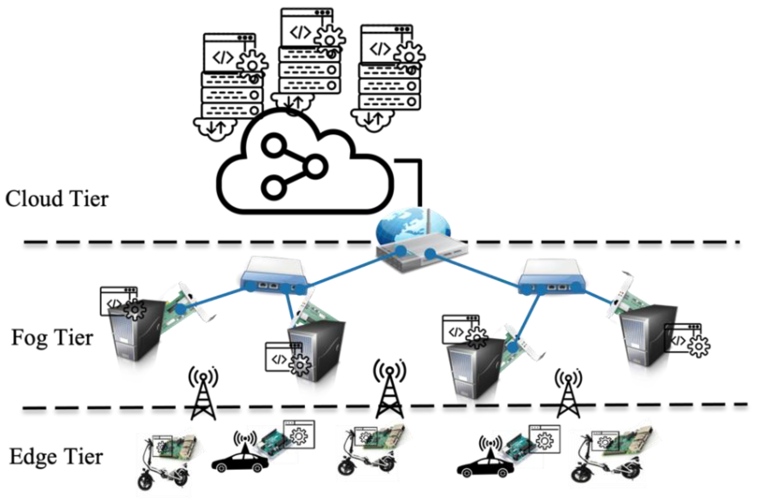
With the introduction of fog computing, the computing paradigm is commonly modeled as a three-tier architecture as presented in Figure 1, which consists of the edge tier, the fog tier, and the cloud tier [16,17]. The edge tier includes end-users IoT devices such as EV, sensors, actuators, and smartphones. Nodes in the edge tier are generally viewed as having limited storage and computing resource capabilities. On the other hand, the fog tier is the intermediate tier that interconnects the edge and the cloud. It is commonly modeled to house thousands of networking devices such as base stations, routers, and gateways which do not only support different communication technologies, such as WiFi, LoRaWAN and 5G, but also have the storage and computational capabilities that can accommodate the computational needs of many edge nodes. Finally, the cloud layer represents cloud datacenters that have very high computational and storage capabilities. The cloud tier is expected to deliver on-demand computing services with high availability and rapid elasticity [18,19].
The edge tier is built using embedded systems. This system composes a set of computer hardware, software, mechanical, and electrical components that work together to accomplish a specific task. Sensors continuously gather information from the environment while the embedded system processes the data to signal actuators in accordance with the mechanics of the controlled process. The microcontrollers accelerate the development of digital gadgets and interactive things that can perceive and manipulate physical objects [20].
The sensor data is evaluated against some parameters in this first step of IoT data processing. This is important because sensors used in EVs are susceptible to noise, which can cause the sensed data to be distorted when communicated. As a result, validating and evaluating the sensor data assures that it is accurate. The data is discarded if it is found to be corrupted. The validation is done at the edge, which saves bandwidth and minimizes the transmission of unneeded data to the Fog and Cloud tiers [21]. After the data has been verified, it is supplemented with additional information to create metadata: the unit, timestamp, location, and unique ID of the sensor.
To the best of the authors’ knowledge, the combination of LoRaWAN within the three-tier computing model and the application of deploying the EV sharing system has not been presented in the literature to deliver on the environment requirement. Hence, this work analysis, designs, implements, and evaluates a LoRaWAN based three-tier solution for the shared mobility system.
3. Methodology and Proposed Approach
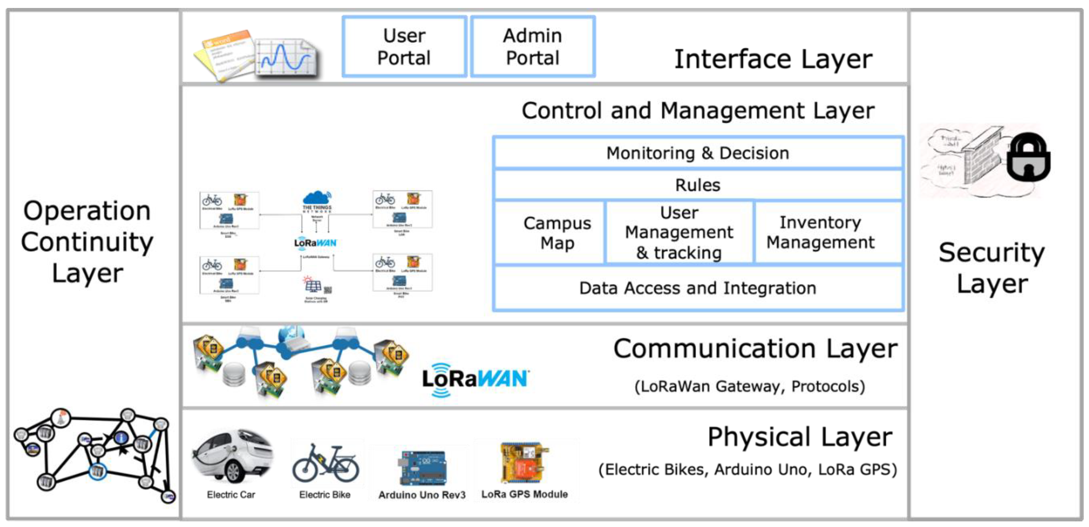
To design an adequate shared mobility system, it is essential to understand the physical environment. Furthermore, to manage the physical assets within the shared mobility environment, a digital transformation of the physical environment is also an essential part of the system. This section explores the shared mobility requirements and characteristics through Figure 2 and is described in detail in the subsections. Each presented layer depends on the layer below it. Furthermore, given the low latency and power consumption requirements, the 3-tier deployment model is presented in Figure 1. The proposed framework objective of the community shared mobility transportation is to:
- Create a digital copy of the physical shared transportation environment for communities.
- Minimize the power consumption of edge computing within the EV by offloading the critical tasks that require real-time decisions to the fog tier with adequate low power communication protocols using LoRaWAN.
- Capture the physical operation of the EV and transfer it to the software layer to deliver on the required core functionalities. The software component instances for critical decisions are to be deployed on the Fog computing tier. The other software component instances are deployed on the cloud computing tier.
- Enable core functionalities to individual users within a community to use the shared EVs and track their usage. Those functionalities must have a modular design for future extensions to the framework.
- Locate the EV within the community and generate specific rules on the usage within the boundaries of the community. The rules govern any notification and alert decisions within the system while tracking the EV in the case of any miss usage. Those decisions based on the defined rules must be done in real-time.
This work proposes the EV shared mobility layered reference model in Figure 2 where the top layer depends on the layer below it to meet the objectives.
Given the two requirements related to the real-time response for latency-sensitive requests and minimizing power consumption from the edge device powered by the EV, we propose the deployment of the designed shared mobility system presented in Figure 2, on the tree-tier computing model presented in Figure 1. Furthermore, selecting an adequate communication protocol is essential to meet the edge power consumption requirement and the support of a long-range communication network. Many works in the literature presented the integration of the LoWRaWAN communication technology to support the low power in communication and the long range support with the public cloud computing integration. To the best of the authors’ knowledge, no work was done in utilizing the LoWRaWAN communication when integrated with the 3-tier computing model for EV shared mobility. This work provides the design and implementation of the EV shared mobility system and its deployment to the 3-tier computing model by utilizing the LoWRaWAN communication technology in the university campus using electric bikes. The latency in the proposed 3-tier model of the implemented system is observed and reported for batch-based requests between 1000 and 10,000 generated from the electric bikes. Experiment results show that the 3-tier deployment has less latency when executing requests when compared to cloud computing. The energy consumption was also observed throughout the experimentation process with and without the edge node.
The detailed description of each layer and its deployment is presented in the subsections.
3.1. Physical Layer
This is the foundation layer of the shared EV transportation infrastructure. This layer specifies the physical entities that operate within the edge tier, such as:
- Electric vehicle (EV): contains an integrated motor to assist or replace riders pedaling. It also uses a rechargeable battery that is used to operate the motor on the EV.
- Microcontroller: used for data collection and processing at the EV node. This includes the main components: processor, storage, and network at the edge.
- GPS Module: this is used for tracking purposes.
This layer also specifies the protocols to enable the integration with the communication layer and processes that allow the physical entities to perform their functions and serve other layers of the EV shared mobility platform. A key function of this layer is to execute the requests generated from the control and management layer. Examples of requests include but are not limited to the warning message to be displayed on the EV screen, applying the brakes on the EV if the individual travels outside of the community boundaries, or unlocking the EV when an individual requests to use an EV.
3.2. Communication Layer
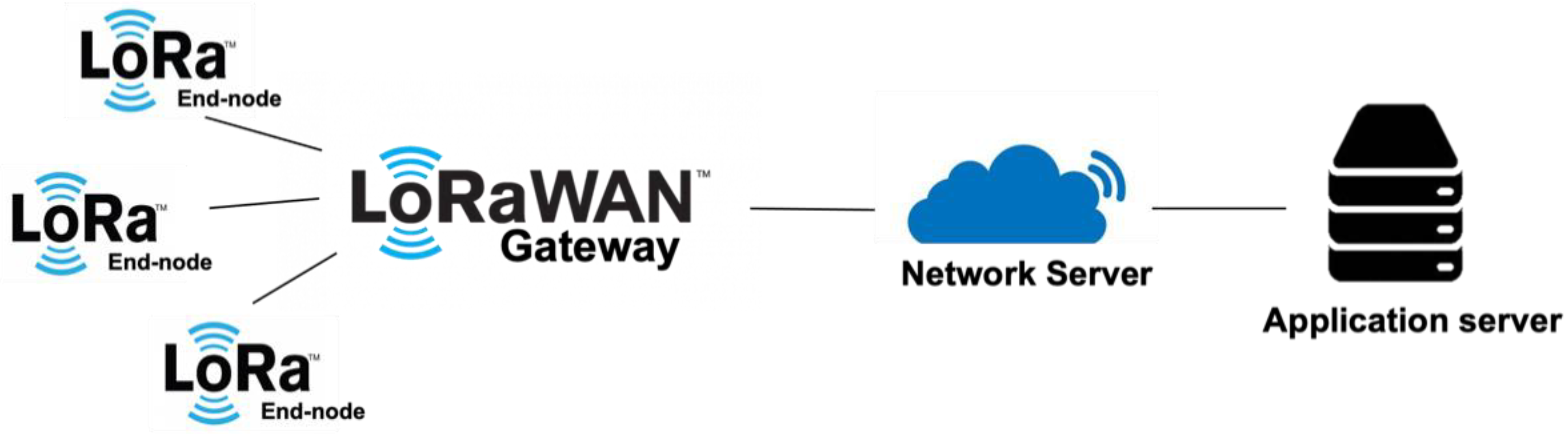
This layer deals with the adequate communication and network technology utilized to enable the transmission and the interaction between the software control and management layer and the physical layer. This layer must also support low-power communication technology for EV shared mobility. Hence, this layer adopts the LoRaWan protocol that consists of the following elements [22] and is presented in Figure 3.
- -
- End-devices: this can be sensors that are capable of communicating wirelessly with gateways using LoRa RF modulation. Those devices are part of the edge tier and battery-powered.
- -
- Gateway: the gateway exists within the LoRaWAN network and is the interface with the IP network such as Ethernet or WiFi. It takes the request packets as an input to the LoRaWAN network, transforms them into IP packets, and forwards the packets to the network server.
- -
- Network server: performs network management within the LoRaWAN network. Among other features, the network server filtrates duplicate or unnecessary packets and handle adaptive data rate schemes. It routes packets from end devices to the associated application server.
- -
- Application server: contains the software components from the control and management layers and the Interface layer.
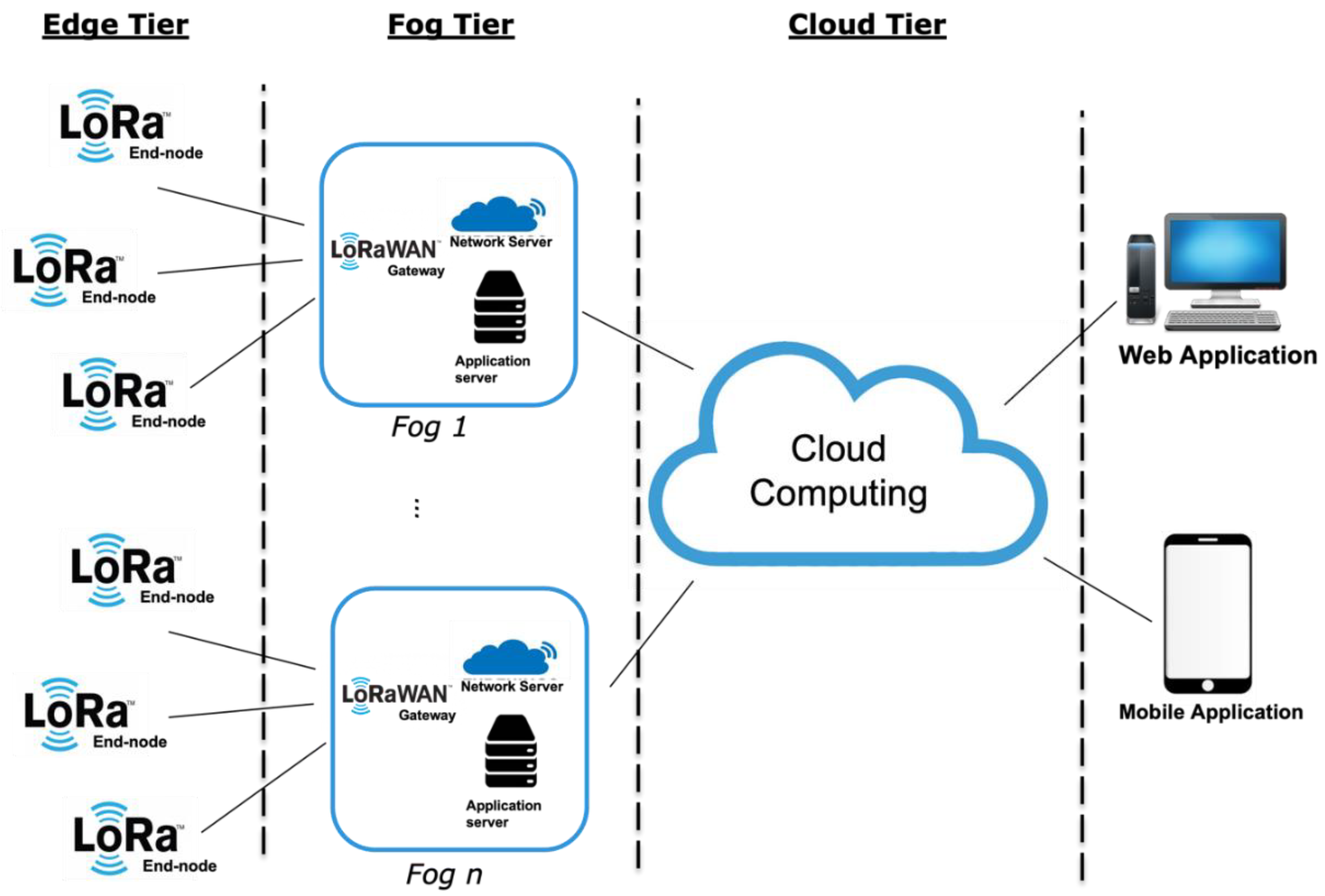
This layer is built on the fog tier. Fog computing enables the computational power at the network close to the edge. Hence, in our deployment of the communication layer within the three-tier computing model, we present a LoRaWAN Fog architecture in Figure 4.
The presented LoRaWAN Fog architecture in Figure 4 integrates the LoRaWAN elements into a single unit. Therefore, in addition to receiving, transforming, and transmitting packets, the LoRaWAN fog tier provides the ability to manage the private network and the modules deployed within the application servers. With such deployment, the fog tier is capable of providing a faster response to critical requests that require low latency. Some of the control and management layer components are to be instantiated at the fog application server.
Requests that are not latency sensitive may not be required to be processed at the fog tier. Hence, those specific requests are forwarded to the cloud servers. Data collected from the EVs that are not required for processing in real-time are forwarded from the fog-tier to the cloud servers directly without consuming the fog computing resources. Furthermore, from the proposed reference model, for example, the interface layer is deployed on the cloud server. Hence, any requests through the EV shared mobility portal can be requested from the cloud directly since those requests are not considered latency-sensitive.
3.3. Control and Management Layer
This layer deals with managing the operation of the EV shared mobility to deliver on the system’s required functionality. One of the key requirements of the framework is to enable the transformation of the physical EV entities (in the physical layer) to a software entity that can be managed and controlled within the control and the management layer. Hence, one of the key modules that deliver on this transformation is the “Data access and Integration.” Once the data is integrated, the core software modules: Inventory management, User Management and Tracking, and Campus map, depend on the data access and integration module. The subsections describe each module in detail.
3.3.1. Data Access and Integration Module
It provides data operation services for sensory devices within the physical layer. It also provides the interfaces with the capabilities to access and store data in the database. The data operation request raised by the modules presented on top of the “Data access and Integration” and the requests from the e-bikes within the physical layer can be categorized as deletion, insertion, query, and update. Despite which type of operation is requested by any consumer modules, the data access module will perform the following tasks: (1) Start transaction management. (2) Access data source through data connection. (3) Check if any extra data operations (such as transformation) is required, and if so, execute them.
Moreover, devices within the physical layer can insert and update data into the database. The data access module will perform the following tasks for devices requests from the physical layer: (1) Start transaction management; (2) Recognize the operation from device ID and event type; (3) Translate generated data from devices to the data source schema. (4) Access data source through data connection. Accessing the database is done by calling the provided interfaces by this module. This hides all the technical details of the operation from the devices and the modules using the data access service.
One of the core functionalities within the data access and integration module is the “Data Transformation.” It provides the necessary transformation of unstructured data to structured data wherever applicable. Mostly, when an EV generates an event, it produces unstructured data that needs to be transformed into structured data in an understandable format by the different modules that consume it.
This module is deployed in both tiers, the fog, and the cloud tiers. In the fog tier, the module monitors the incoming data. If the incoming data is classified as part of the latency-sensitive requests, the data is processed at the fog application server. Any actions are to be transferred back to the edge node. Otherwise, the fog’s “Data Access and Integration” module forwards the acquired data to the “Data Access and Integration” module deployed on the cloud.
3.3.2. Inventory Management
This module provides the ability to add a new EV to the system by registering it, update the data associated with the EV and its availability at a specific time. It also enables deregistering an EV. The inventory management module has the following main functionalities:
- Registration: this module handles the registration of the EV into the system. It takes in the following parameters: name, identification, and current location.
- Status update: this module allows the status update of the EV at a specific time. The EV status can be in one of the following:
- -
- Available: an individual can use the EV.
- -
- Unavailable: in use by a particular individual.
- -
- Attention: admins need to check on the EV physically, and it will be unavailable for usage.
- Maintenance: the EV is under maintenance and unavailable for use.
- Unregister: this enables admins to unregister an EV from the system.
3.3.3. User Management and Tracking Module
This module provides the ability to add, delete, and update individuals within the community to allow them to use an available EV within the community-defined boundaries. Each user can be in one of the following statuses:
- Active: once a user is registered in the system, they have the active status. A user with the active status is allowed to use an available EV.
- Suspended: a user that miss uses the EV will have the suspended status. A user with the suspended status is not allowed to use an EV.
3.3.4. Tracking Module
This module provides the ability to track the EV’s location and the usage of each individual while using the EV. It provides one of the foundations of rules created to enable the usage of the EV within a defined boundary of the community.
3.3.5. Community Map Module
This module enables the customization of the community map. The module provides the ability to:
- -
- Add and delete a community map.
- -
- Identify roads for the EV to be used within the map.
- -
- Identify the availability of charging stations.
- -
- Identify the available pick and drop off locations within the community.
- -
- Identify specific landmarks within the community.
3.3.6. Rules Module
This module provides the ability to add specific constraints related to the community as the EV are consumed by individuals. Some of these rules can be related to driving the EV beyond the allowed boundaries. The rule can take the form of “if condition, then action.” The rules module consists of the following main functionalities:
- -
- Create/delete/edit conditions.
- -
- Create/delete/edit actions.
- -
- Associate one and/or more conditions to one and/or more action.
The defined rules can be further classified as time-sensitive or not. The defined rules as time-sensitive are transferred to the fog tier for monitoring. The other rules that are not time-sensitive are to be monitored at the cloud tier.
3.3.7. Monitoring and Decision Module
This module monitors the created rules conditions. This module is deployed in both the fog tier and the cloud tier. The module monitors the time-sensitive rules within the fog tier and executes the actions if the defined condition is true. At the cloud tier, the rules that are not time-sensitive are continuously monitored and executes on the actions if the condition evaluates to true.
3.4. Interface Layer
The interface layer specifies the entities that can interface with the system through a provided user interface. An admin portal and the regular user portal are presented to the different user roles. A key function of this layer is to present the information about all the services offered to the specific user role. For the regular user, it exposes the services offered by the EV shared mobility system that includes various information about the services, such as the description of the services, the types of services, cost, rules, etc. Furthermore, this layer enables regular users to access and manage rented service instances. The requests are passed on to the control and management layer to fulfill those requests. The interface layer also exposes functionalities to the administrator user role, allowing them to view and manage the operation of the EV assets and the overall platform.
3.5. Security Layer
Security is a cross-layer, which specifies the adoption of administrative and technical mechanisms to minimize security threats and provide a secure EV shared mobility platform. This cross-layer supports all the presented layers—physical, communication, control and management, and interface—to provide secure services to the consumers. The layer supports both administrative and technical mechanisms to provide a safe execution of the provided services by the EV shared mobility system.
The detailed risks, vulnerability, attacks, and defense mechanisms are beyond the scope of this paper.
3.6. Operation Continuity Layer
Operation continuity is a cross-layer function that specifies the adoption of proactive and reactive measures that enable the EV shared mobility platform to mitigate the impact of planned and unplanned downtime. Proactive measures include activities, tasks, processes such as impact analysis, risk assessment, and technology solutions deployment (such as backup and replication). Reactive measures include activities, tasks, processes to be invoked in the event of a failure. It supports all the layers—physical, communication, control and management, and service—to provide uninterrupted services to the consumers.
The details of the risks, proactive and reactive mechanisms are beyond the scope of this paper.
4. Prototype Implementation
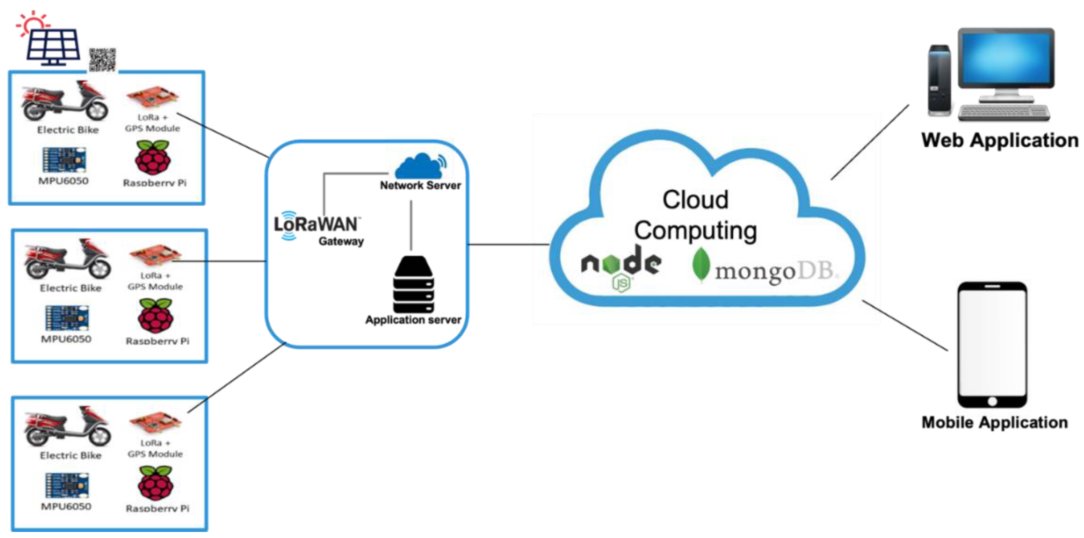
To validate the proposed system architecture presented in Section 3, the proposed shared mobility platform was implemented in a University campus environment using e-bikes. Figure 5 illustrates the edge, fog, cloud computing implementation prototype, and deployment.
The implemented physical layer contains four hardware components: (1) The Arduino Uno microcontroller, (2) the Dragino LoRa end-node [23], (3) the GPS shield, (4) the e-bike.
The Arduino microcontroller periodically sends the location of the e-bike, speed, direction, acceleration, and the bike ID via LoRa end node shield attached to an Arduino Un to the LoRaWAN gateway presented in the communication layer and deployed on the fog tier at the e-bike charging station.
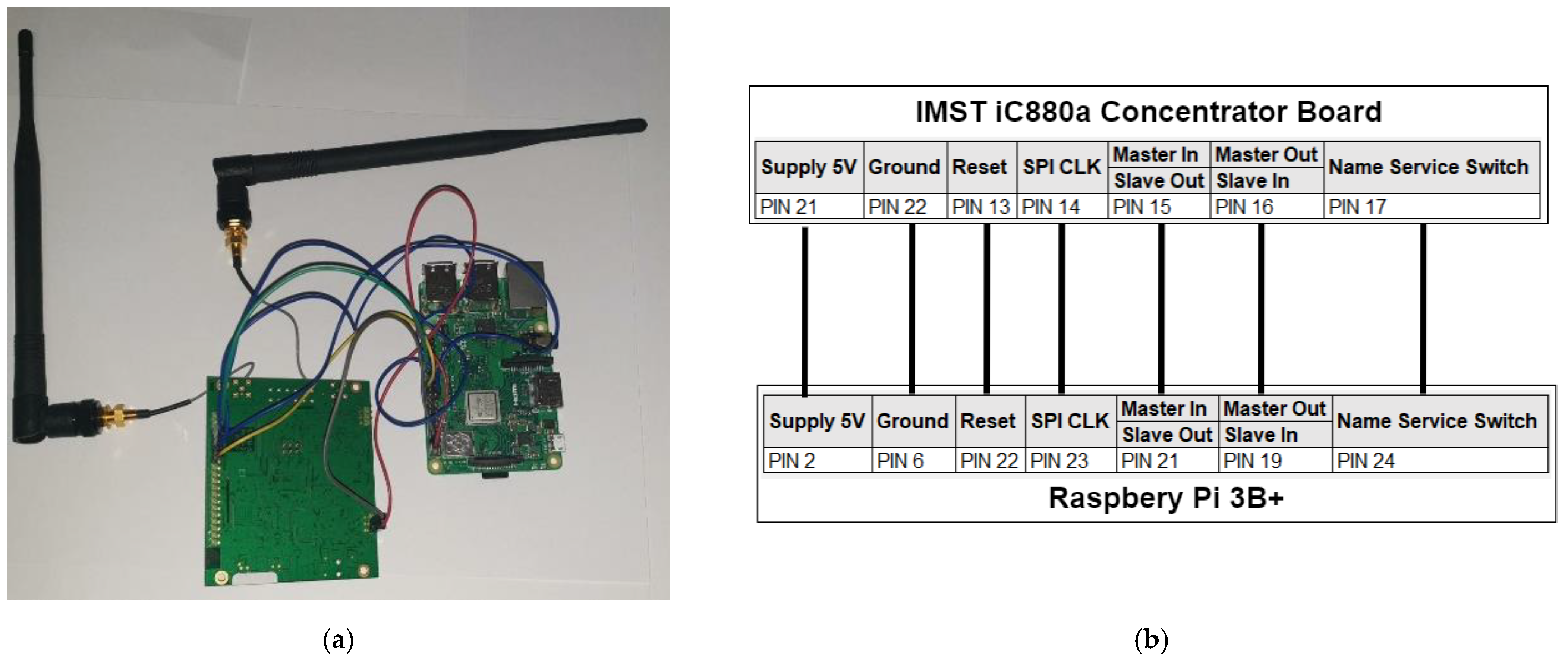
The packets are encoded at the embedded device and decoded at the network server after being forwarded by the LoRaWAN gateway. The LoRaWAN gateway was created using a Raspberry Pi [24] as well as an IMST iC880A LoRaWAN concentrator. The gateway has a gain of 3 dBi, and testing has shown that over one kilometer of the range was achieved with the gateway being placed outdoors.
The LoRa packets are encrypted within the communication layer with application and network keys and then broadcast via LoRa modulation to the gateway. The LoRaWAN gateway is implemented with a Raspberry Pi 3B+, 3dBi Antenna, and the IMST iC880A-SPI concentrator board [25], as shown in Figure 6.
The LoRa gateway enables LoRa packets to be communicated over IP networks. The sensor data from the LoRa end-node on the e-bike is sent to the LoRa gateway, which in turn sends the packet to a software packet forwarder.
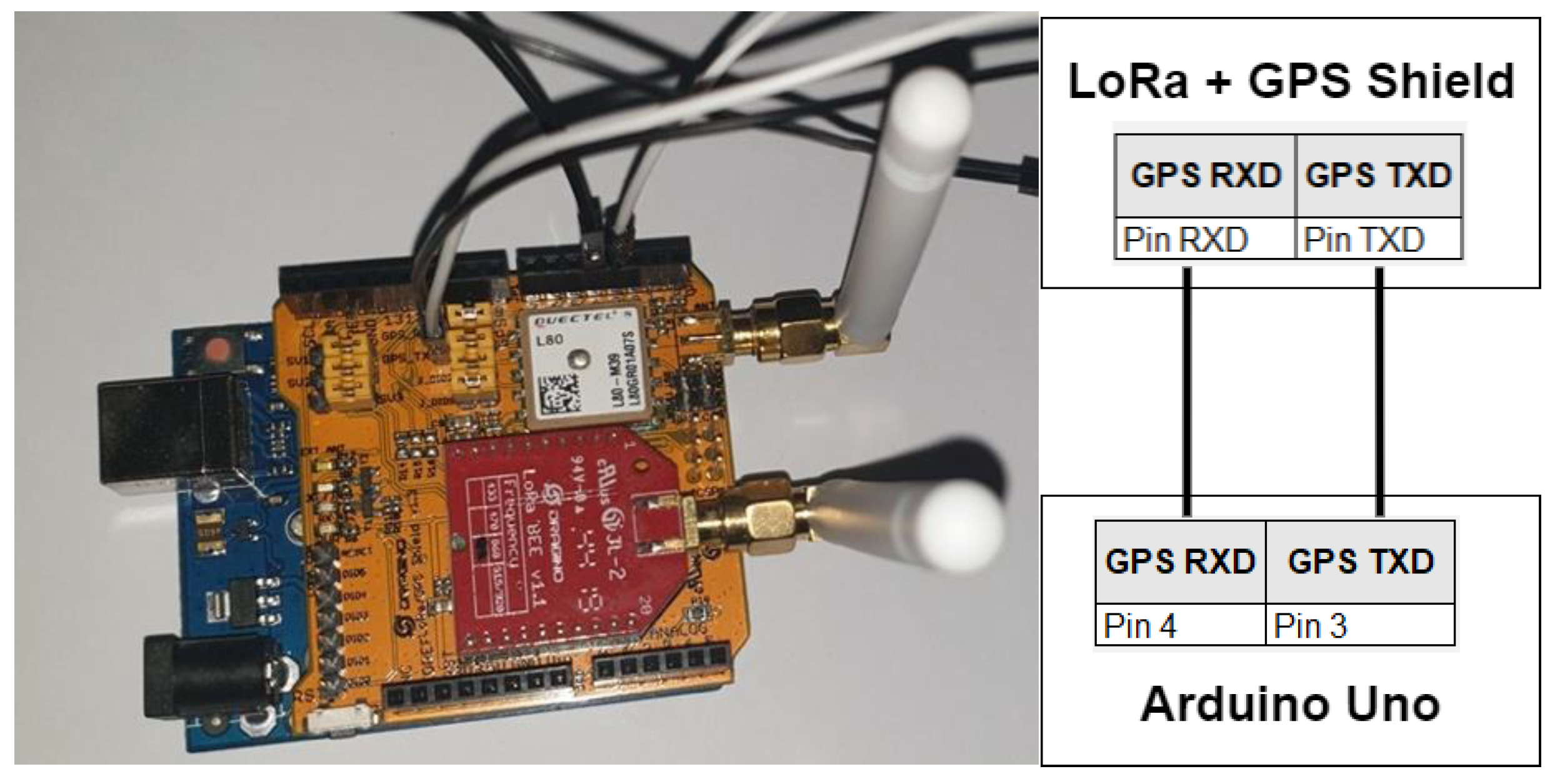
The components used for creating the LoRa Endnode are Arduino and Dragino LoRa + GPS shield. The assembled hardware and connection diagram for the prototype implementation of the LoRa Endnode is presented in Figure 7.
A LoRa Endnode connects to a LoRaWAN gateway to send the sensor’s data. This LoRa Endnode is attached to the bike to transmit sensor information such as GPS coordinates for location tracking. This is powered by the bike’s internal battery, making it an edge device. The LoRa Endnode has a radio frequency transmitter module that utilizes LoRa modulation on the sub-gigahertz radio frequency band (868 MHz). The low frequency of the LoRa technology allows for transmission of packets over large distances; during the testing of transmission distances, a range of over a kilometer with a gateway antenna of only 3 dBi was achieved. The radiofrequency module is attached to a shield that has a GPS module attached. This allows the software written on the embedded device to interface with both the frequency module as well as the GPS module, the software was written in the C language. The GPS module uses the traditional technique of communicating with satellites to triangulate the location of the bike. The latitude and longitude floating precision value is encoded into an 8-byte array memory buffer. Since the ID of the bike the embedded device is on also needs to be specified, an integer is encoded into a 4-byte array and appended onto the previously mentioned buffer creating a 12-byte array memory buffer. These encoded 12-bytes are then encrypted using an application and network key and transmitted using LoRa modulation to the LoRaWAN. The total size of the payload is around 25 bytes and the LoRa module uses a Chirp Spread Spectrum (CSS) technique making it robust to channel noise.
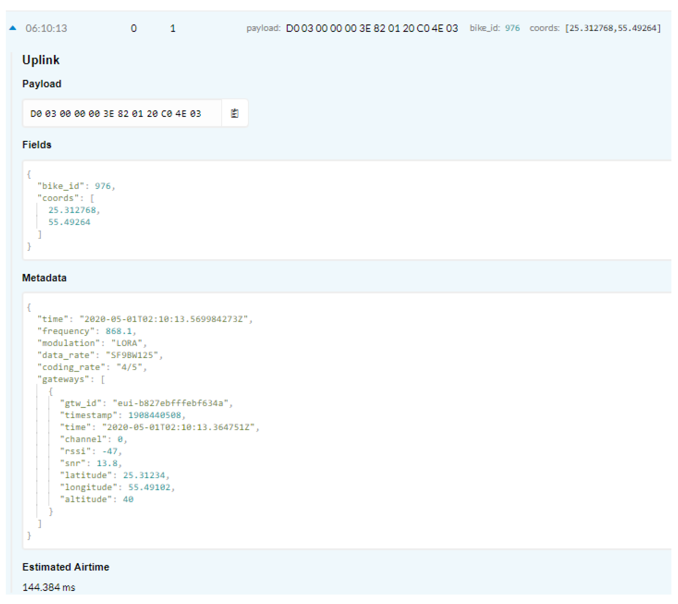
The packet forwarder sends the packets to a network server hosted on campus premises. The packets are decrypted and forwarded to the application server within campus premises over Message Queuing Telemetry Transport (MQTT). Figure 8 shows the decrypted payload by the network server. The data is then collected by the “data access and integration component” deployed on the fog tier in the Application server, which monitors the incoming data, and publishes to the subscribed services within the fog tier the required data needed to make decisions. The data that is not registered to be integrated at the fog tier is forwarded to the cloud data access and integration component that is deployed on the cloud server.
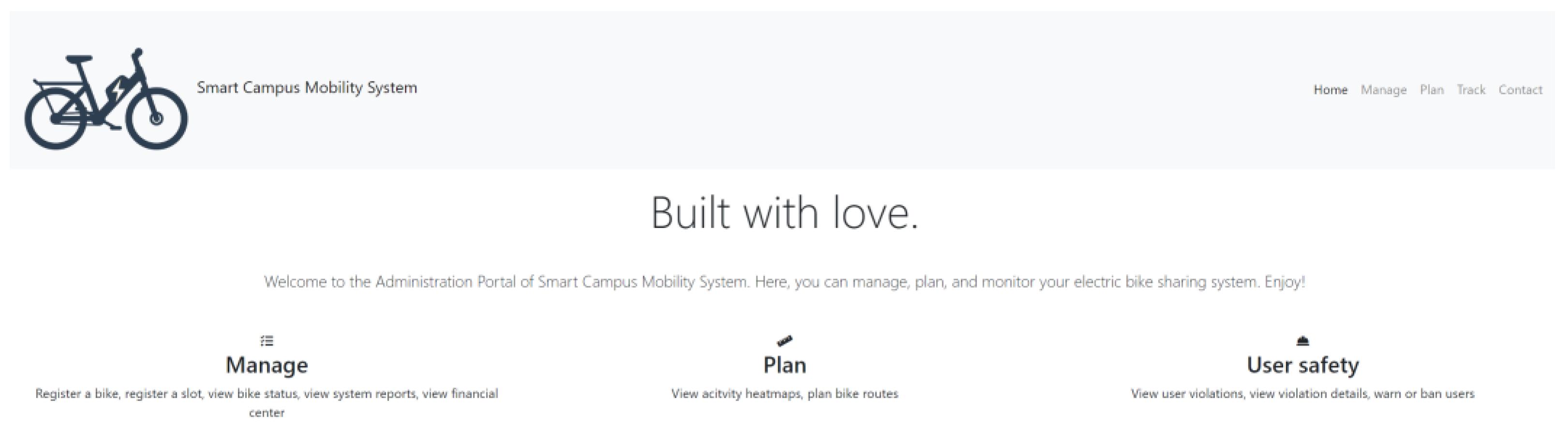
Mobile and web interfaces were implemented as part of the interface layer presented in Figure 1 and deployed on the cloud server to use the shared mobility application. The web administration interface enables administrators to monitor and modify the working of the shared bike system. The web portal is implemented using HTML, CSS, Javascript, and Bootstrap. Using the administration interface, admins can add new e-bikes and bike slots, create other admin users, and get all the near real-time information of any bike in the system through the control and management layer. Moreover, the cost feature in the web application allows the administrators to see a breakdown of revenue generated.
Figure 9 presents the main features provided to administrators and are classified as Manage, Plan, and User safety. In brief, the Manage section allows the administrator to register a bike, register a slot, view the status of any bike, view system reports, and view the financial center.
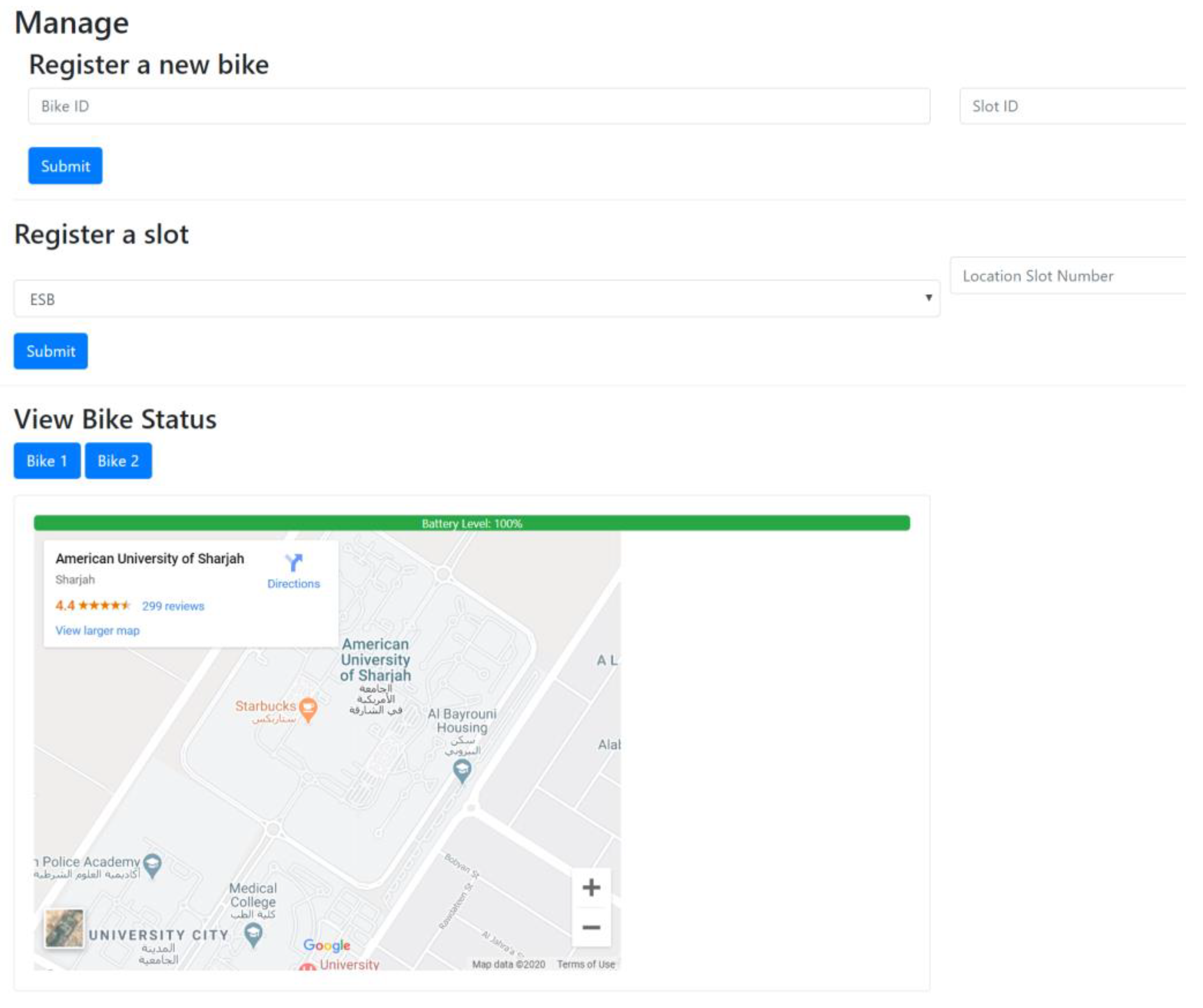
The manage feature of the dashboard allows administrators to add other administrator users and register new e-bikes to the system as presented in Figure 10 by providing its Bike ID and the Slot ID to where the bike is placed. The administrator can register a slot for different locations on campus. Any of the statuses of the e-bikes can be viewed by clicking on the respective e-bike label. The battery level of the electric bike and its current location is presented on a map. By clicking on the button to view the e-bike data, a request will be sent to the server for the respective data. As a response, the server will return the geographical coordinates and the bike’s battery level, which the user interface will show. Furthermore, the administrator can view the number of slots allocated to each location and the number of e-bikes currently parked at each location. The control and management layer updates this data, which presents the administrator dashboard information on the current slots used and the e-bikes in use at respective locations.
As part of the planning, the administrator can also view the activity hotspots in real-time. This map shows the administrator the areas that are currently covered by the e-bikes in use. The Plan Bike Routes is a feature that the management can use to allocate more bike routes if there is a demand. The server returns a list of geographical coordinates, which the administrator dashboard converts into activity hotspots on the map.
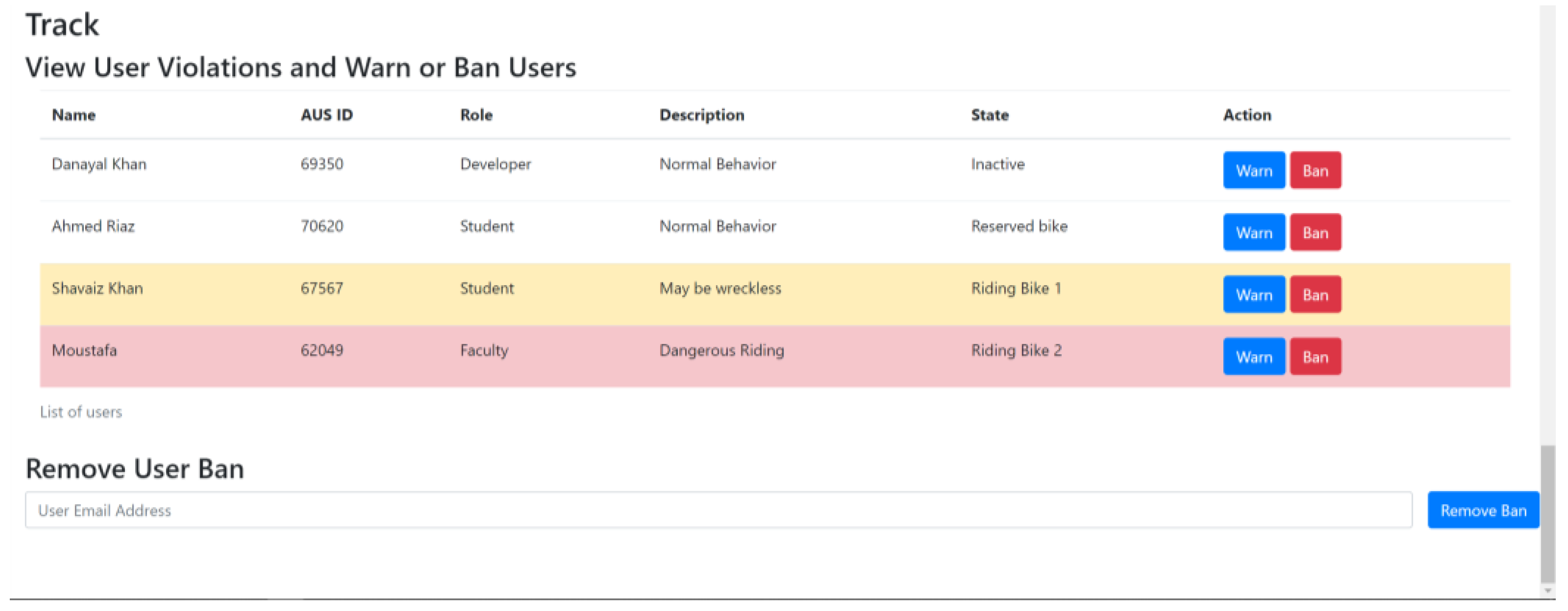
The administrator may also track users and their behavior in real-time. The administrator can view which e-bike is being operated by which user and if any users have reserved a bike. If they receive complaints about certain users or the bike sensors detect irrational bike riding, the administrator can either warn, fine, or ban users. The server returns the list of the users as it stores the list of users and their respective information in the MongoDB database, as shown in Figure 11. A request is sent to the server to perform the appropriate action by clicking on warn or ban.
An essential feature of the web portal is adding rules that define reckless riders and accidents. In the prototype implementation, a speed-related rule, bike drop rule, and geofencing rule were created by the admin user. Those specific rules were pushed into the fog layer to be monitored with the particular data required to be monitored for the defined rules, such as accelerometer and gyroscopes, and location data. As the stream of data arrives at the fog’s data access and integration layer, the rules are monitored and a decision is to warn the rider in the case of speeding. A defined rule to fine the rider if they ignore the speeding warning three times.
Furthermore, if a fall is detected, a message is sent to the rider and monitoring the movement through the accelerometer sensor data for the specific bike. If no activity within a set threshold, 15 s is the set threshold in the implemented prototype, a campus security officer within range is messaged with the e-bike location. Fall detection could be a sign of health hazard or injury, and it could be a misuse of the e-bike. Accordingly, the system will provide the security to respond to the option if the rider requires medical attention; if the option is selected, the ambulance number is called. Otherwise, if it was a misuse of the e-bike, the “report misuse” option is selected by the security officer, and they provide the details and an image of the current state of the e-bike. Such a case is escalated further with the maintenance team to report the cost of the misuse.
Another implemented rule to be monitored by the fog tier is the location of the e-bike. If the rider takes the e-bike outside the defined boundary, a warning message is sent to the rider, and the “brake” action is applied gradually to the e-bike to prevent them from moving any further. The security officer within the range of the rider will be notified for further action.
In order to use the shared mobility services, users must install the developed mobile application. This application enables the user to reserve an e-bike, claim the e-bike after reserving it, view ride history and cost center, receive warnings of careless usage and emergencies, and contact the administration.
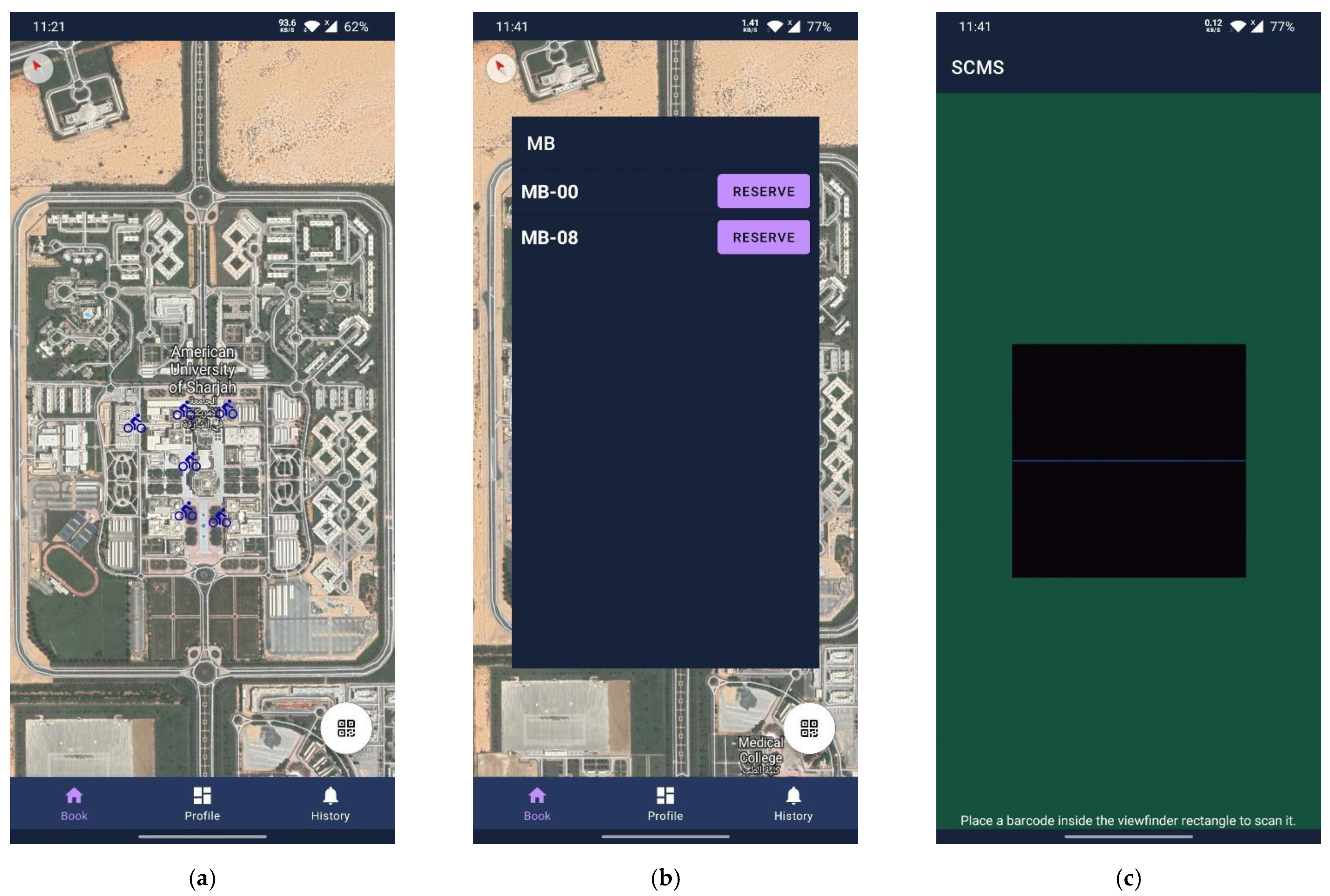
To book and claim an e-bike, the logged-in user may view the university campus map with available charging stations indicated with icons of a blue bike, as shown in Figure 12. To book a ride, the user must tap on the icon of a charging station to view all the current available e-bikes on the selected charging station. The displayed e-bikes are the ones that are not in use nor reserved. The user can tap on one of the e-bikes to reserve it, as shown in Figure 12. Suppose the reservation is successful (indicated by a response of {status:1} from the server). In that case, a five-minute timer (a configurable timer by the administrator within the system) is started on the server. The user must claim the bike within this time limit. Otherwise, the reservation is canceled, and the e-bike will be available for others to reserve. The user will be unable to reserve or claim bikes if they have already reserved a bike, are currently in a ride or have been banned by the system.
To claim an e-bike, the user must go up to the charging station and locate the reserved bike. They must then scan the QR code on the bike slot. This QR code will be decoded, and the resulting string will be sent to the server for confirmation. If successful, the user will be able to claim the bike. The server notes down the starting time and position of the bike, as these parameters are a part of the ride history. To return an e-bike to a charging station, the user must go up to a free parking spot and park the borrowed bike, and then scan the QR code on the bike slot where they parked the bike. If they scanned the QR code of a free bike slot, their ride ends. The user can see the details of the ride in the history section of the application.
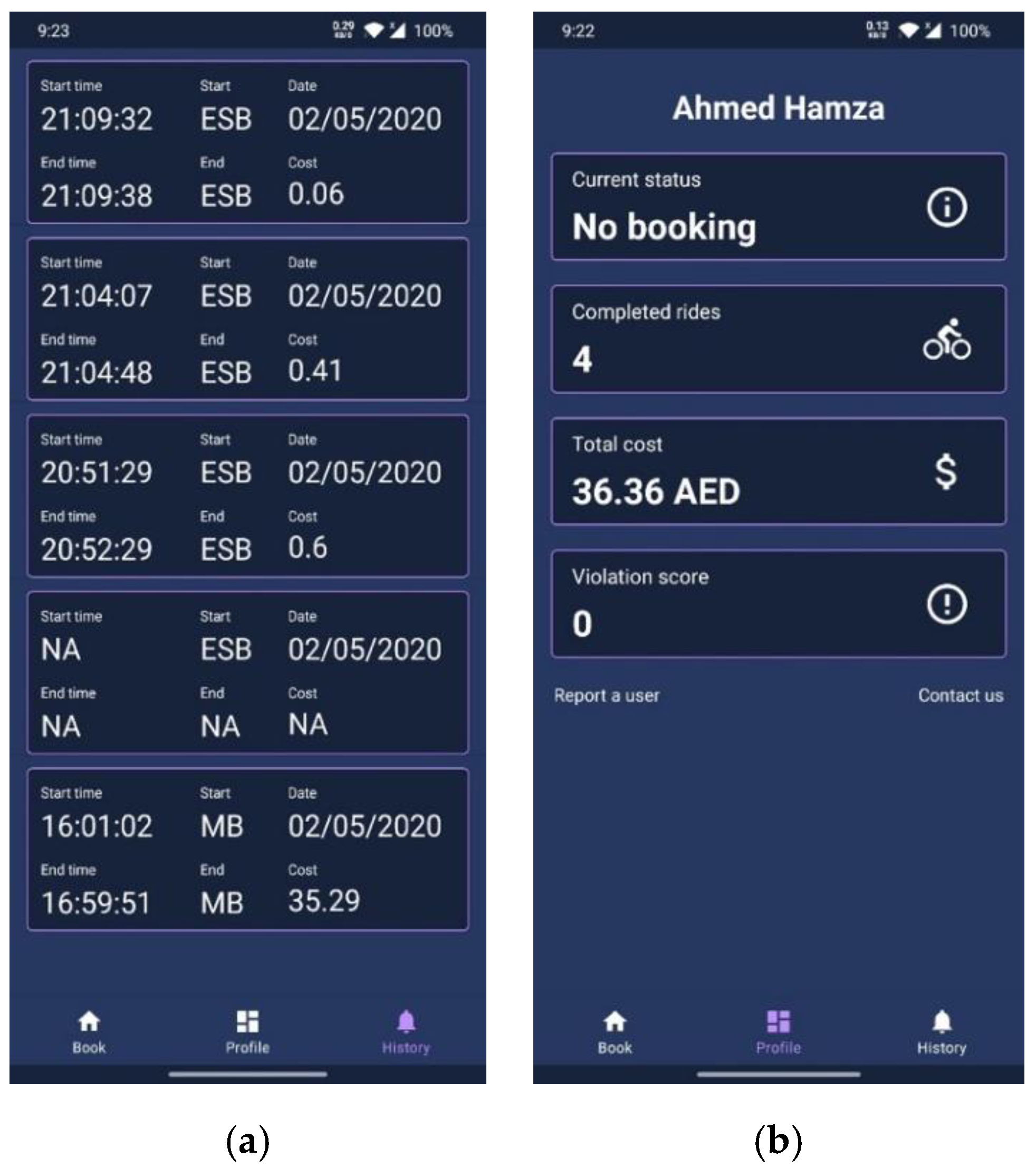
The user can view all previous rides in the history section of the application, as presented in Figure 13a. Also, the cost, initial and final destinations, and the ride duration are displayed, as shown in Figure 13b. All the features mentioned above in the user and admin interfaces are functionalities exposed by the control and management layer, as discussed in Section 3.
The physical implementation and testing dealt with a single e-bike. Other bikes were simulated within the university campus environment to test the system’s scalability to support multiple e-bikes and users. The prototype implementation presented the adequacy of the proposed architecture with the university campus and its ability to scale to multiple e-bikes and users.
5. Results and Discussion
Given the proposed architecture in Figure 5, and since the time dimension with the fog computing architecture is a critical factor, this section presents the conducted experiments to measure the execution time of the gateway, network server, and application server within the fog tier. The execution time of each element was measured as follows:
- -
- Gateway: from the time the message was received until it was forwarded to the network server.
- -
- Network server: from the time the network server received the message until the message was processed and forwarded to the application server.
- -
- Application server: from the time the message is received until the decrypted payload is added to the database.
The experiment was conducted with 1000, 5000, and 10,000 requests. The average execution time for the experiments is presented in Table 1, Table 2 and Table 3, respectively.
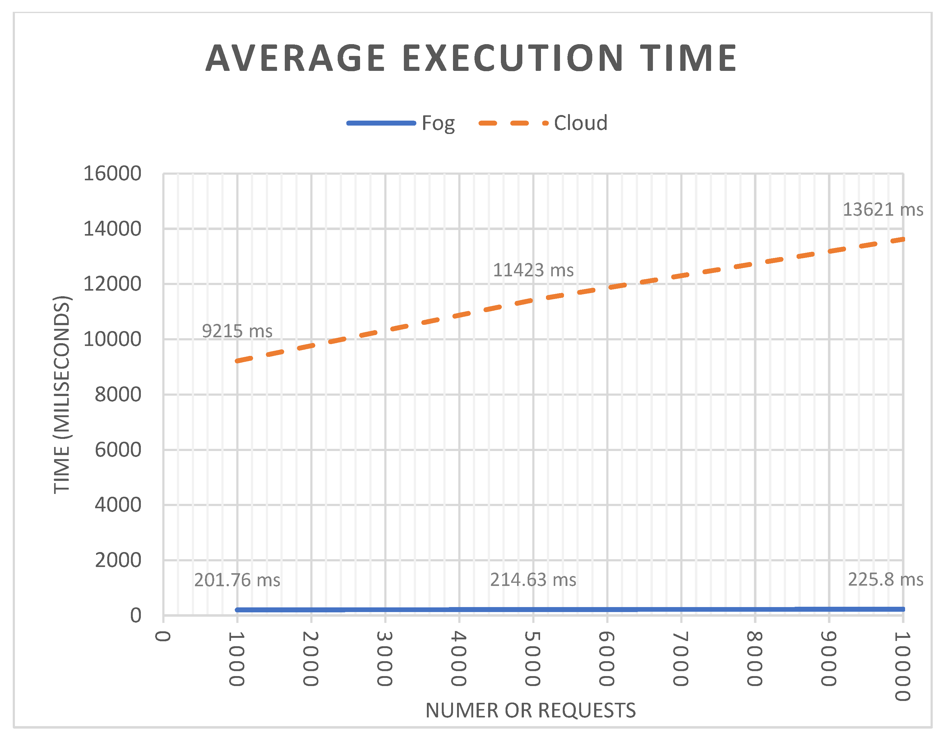
From Table 1, the average latency of 1000 requests within the fog computing tier is 201.76 ms. As the number of requests increases to 5000 and 10,000 requests, the average latencies are 214.63 ms and 225.80 ms, respectively. Hence, given the nature of the smart mobility community, it is expected to receive requests within the range of 1000 to 10,000 requests at a specific point in time. Therefore, the proposed solution scales as the number of requests increase. Furthermore, the proposed architecture is modular, and as the number of requests increases, and if there is a need to have additional network and applications servers, more compute nodes can be added at run-time using network and application load balancers.
Further experimentation was conducted to examine the execution of tasks using cloud computing without the Fog computing implementation. The results are presented in Table 4 for 1000, 5000, and 10,000 requests. The execution time was calculated from the time the requests were initiated from edge devices until the request was processed and transmitted back to the edge device. For this experiment, a public cloud provider is used, and the developed framework is deployed on a server in the US East region. The difference in average execution time is noticeable when compared fog only versus cloud only execution, as shown in Figure 14.
The power consumption was also observed while the e-bike was in use with the utilized LoRaWAN technology. The e-bike operation time with an average use was observed with and without the utilization of the LoRaWAN end node sending packets. There was no noticeable power drainage during the operation of the e-bike while transmitting the LoRaWAN packets. In both scenarios, with and without sending the LoRaWAN packets, the e-bike was able to travel a range between 40 and 50 KMs.
6. Conclusions
This work proposed an architectural design for e-vehicles within a community setting. The proposed architecture was validated through a prototype implementation using e-bikes within a university campus. The proposed architecture consists of four main layers: the physical layer, communication layer, control and management layer, interface layer, operation continuity layer, and security layer. A mobile application was developed to enable regular users to use the system’s main functionalities and a web interface for administrators to register and track the e-bikes in the physical environment. The e-bike can be used in university campuses, public parks, large malls and closed residential communities, and sports complexes. The work conducted a set of experiments to examine the adequacy of the proposed architecture using the LoRaWAN technology for fog computing in smart mobility sharing with respect to latency, scalability, and energy consumption. The results show that with the LoWRaWAN fog computing for smart mobility was able to handle the execution of requests between 1000 and 10,000 with an average execution time in fractions of seconds when compared with cloud computing. Furthermore, the system’s modular design provides the ability to deploy components in different nodes with the ability to provision additional servers at run-time for components to scale when there is a high number of requests at a specific point in time. We also observed the power consumption in the prototype implementation with the e-bike shared mobility with and without the LoRaWAN end node. It was observed that LoRaWAN does not consume a noticeable power from the e-bike battery during a normal operation. Future work will examine other network protocols that utilize WiFi and 5G networks. We will further collect real data from users within the university campus community and extend the proposed architecture with the analytics and prediction services.
Author Contributions
Conceptualization, R.A., A.H.R.; Investigation, R.A., A.R.A.-A., A.H.R., D.K., S.K., M.A.; Methodology, R.A., A.R.A.-A., A.H.R., S.K.; Software, A.H.R., D.K., S.K., M.A., A.A.N., R.A.; Supervision, R.A., A.R.A.-A.; Writing—R.A., A.R.A.-A., A.H.R., A.A.N., D.K., S.K., M.A. All authors have read and agreed to the published version of the manuscript.
Funding
This research was funded by the American University of Sharjah undergraduate research grant URG-20-003. The work in this paper was supported, in part, by the Open Access Program from the American University of Sharjah. This paper represents the opinions of the author(s) and does not mean to represent the position or opinions of the American University of Sharjah.
Conflicts of Interest
The authors declare no conflict of interest.
References
- Al-Shariff, S.; Alam, M.; Ahmad, Z.; Ahmad, F. Smart Transportation System: Mobility solution for Smart Cities. In Proceedings of the 2nd Smart Cities Symposium (SCS 2019), Bahrain, 24–26 March 2019; p. 59. [Google Scholar]
- Butler, L.; Yigitcanlar, T.; Paz, A. Smart Urban Mobility Innovations: A Comprehensive Review and Evaluation. IEEE Access 2020, 8, 1. [Google Scholar] [CrossRef]
- Gimon, D. Bike commuters contribution to balance shared bike systems during peak load. In Proceedings of the 2018 IEEE International Smart Cities Conference (ISC2), Kansas City, MO, USA, 16–19 September 2018; pp. 1–2. [Google Scholar]
- Alaoui, E.A.A.; Tekouabou, S.C.K. Intelligent management of bike sharing in smart cities using machine learning and Internet of Things. Sustain. Cities Soc. 2021, 67, 102702. [Google Scholar] [CrossRef]
- Al-Ali, A.R.; Aburukba, R.; Riaz, A.H.; Al Nabulsi, A.; Khan, D.; Khan, S.; Amer, M. IoT-Based Shared Community Transportation System Using e-Bikes. In Proceedings of the 2021 5th International Conference on Smart Grid and Smart Cities (ICSGSC), Tokyo, Japan, 18–20 June 2021; pp. 61–65. [Google Scholar]
- Sun, L.; Wang, S.; Liu, S.; Yao, L.; Luo, W.; Shukla, A. A completive research on the feasibility and adaptation of shared transportation in mega-cities—A case study in Beijing. Appl. Energy 2018, 230, 1014–1033. [Google Scholar] [CrossRef]
- Böcker, L.; Anderson, E.; Uteng, T.P.; Throndsen, T. Bike sharing use in conjunction to public transport: Exploring spatiotemporal, age and gender dimensions in Oslo, Norway. Transp. Res. Part A Policy Pract. 2020, 138, 389–401. [Google Scholar] [CrossRef]
- Li, H.; Zhang, Y.; Ding, H.; Ren, G. Effects of dockless bike-sharing systems on the usage of the London Cycle Hire. Transp. Res. Part A Policy Pract. 2019, 130, 398–411. [Google Scholar] [CrossRef]
- Tang, Y.; Pan, H.; Shen, Q. Bike-Sharing Systems in Beijing, Shanghai and Hangzhou and Their Impact on Travel Behavior, Velo-City Vancouver 2012. Available online: https://pdfs.semanticscholar.org/4eb1/438c49b88bbb9a126336a97251636f366859.pdf (accessed on 22 September 2021).
- Teixeira, J.F.; Lopes, M. The link between bike sharing and subway use during the COVID-19 pandemic: The case-study of New York’s Citi Bike. Transp. Res. Interdiscip. Perspect. 2020, 6, 100166. [Google Scholar] [CrossRef] [PubMed]
- Ibrahim, D.M. Internet of Things Technology based on LoRaWAN Revolution. In Proceedings of the 2019 10th International Conference on Information and Communication Systems (ICICS), Irbid, Jordan, 11–13 June 2019; pp. 234–237. [Google Scholar]
- Queralta, J.P.; Gia, T.; Zou, Z.; Tenhunen, H.; Westerlund, T. Comparative Study of LPWAN Technologies on Unlicensed Bands for M2M Communication in the IoT: Beyond LoRa and LoRaWAN. Procedia Comput. Sci. 2019, 155, 343–350. [Google Scholar] [CrossRef]
- Gu, F.; Niu, J.; Jiang, L.; Liu, X.; Atiquzzaman, M. Survey of the low power wide area network technologies. J. Netw. Comput. Appl. 2020, 149, 102459. [Google Scholar] [CrossRef]
- Zourmand, A.; Hing, A.L.K.; Hung, C.W.; AbdulRehman, M. Internet of Things (IoT) using LoRa technology. In Proceedings of the 2019 IEEE International Conference on Automatic Control and Intelligent Systems (I2CACIS), Selangor, Malaysia, 29–29 June 2019; pp. 324–330. [Google Scholar]
- Mouradian, C.; Naboulsi, D.; Yangui, S.; Glitho, R.H.; Morrow, M.J.; Polakos, P.A. A Comprehensive Survey on Fog Computing: State-of-the-Art and Research Challenges. IEEE Commun. Surv. Tutor. 2018, 20, 416–464. [Google Scholar] [CrossRef] [Green Version]
- Mukherjee, M.; Shu, L.; Wang, D. Survey of fog computing: Fundamental, network applications, and research challenges. IEEE Commun. Surv. Tutor. 2018, 20, 1826–1857. [Google Scholar] [CrossRef]
- Hu, P.; Dhelim, S.; Ning, H.; Qiu, T. Survey on fog computing: Architecture, key technologies, applications and open issues. J. Netw. Comput. Appl. 2017, 98, 27–42. [Google Scholar] [CrossRef]
- Gong, C.; Liu, J.; Zhang, Q.; Chen, H.; Gong, Z. The Characteristics of Cloud Computing. In Proceedings of the 2010 39th International Conference on Parallel Processing Workshops, San Diego, CA, USA, 13–16 September 2010; pp. 275–279. [Google Scholar]
- Puthal, D.; Sahoo, B.; Mishra, S.; Swain, S. Cloud Computing Features, Issues, and Challenges: A Big Picture. In Proceedings of the 2015 International Conference on Computational Intelligence and Networks, Odisha, India, 5 March 2015; pp. 116–123. [Google Scholar]
- Srirama, S.N. Mobile web and cloud services enabling Internet of Things. CSI Trans. ICT 2017, 5, 109–117. [Google Scholar] [CrossRef]
- Datta, S.K.; Bonnet, C. An edge computing architecture integrating virtual IoT devices. In Proceedings of the 2017 IEEE 6th Global Conference on Consumer Electronics (GCCE), Nagoya, Japan, 24–27 October 2017; pp. 1–3. [Google Scholar]
- Jalowiczor, J.; Gresak, E.; Rezac, F.; Rozhon, J.; Safarik, J. Development and deployment of the main parts of LoRaWAN private network. Auton. Syst. Sens. Process. Secur. Veh. Infrastruct. 2019. [Google Scholar] [CrossRef]
- Lora Shield. Lora Shield—Wiki for Dragino Project. Available online: https://wiki.dragino.com/index.php?title=Lora_Shield (accessed on 22 September 2021).
- Raspberry-Pi. Available online: https://www.raspberrypi.org/ (accessed on 22 September 2021).
- IC880A-Lora Concentrator Module. Wireless Solutions, 22-Mar-2021. Available online: https://wireless-solutions.de/products/lora-solutions-by-imst/radio-modules/ic880a-spi/ (accessed on 22 September 2021).
Figure 1.
The 3-Tier Computing Model.

Figure 2.
EV shared mobility reference model.

Figure 3.
Standard LoRaWAN Elements.

Figure 4.
LoRaWAN Fog-Tier Architecture.

Figure 5.
Prototype Implementation of the Proposed System.

Figure 6.
LoRaWAN Gateway (a) Hardware View of the Implementation. (b) Connection Diagram for the LoRaWAN Gateway.
Figure 6.
LoRaWAN Gateway (a) Hardware View of the Implementation. (b) Connection Diagram for the LoRaWAN Gateway.

Figure 7.
LoRa Endnode Hardware and Connection Diagram.

Figure 8.
Decoded decrypted payload with sensor information at the network server.

Figure 9.
Main presented features for the admin users.

Figure 10.
Manage view to register a new e-bike and view registered e-bike status.

Figure 11.
Track Users Administrator View in the Web Portal.

Figure 12.
User Mobile Interface (a) Map of Campus with charging stations. (b) Reserve an e-bike interface. (c) QR code scanner.
Figure 12.
User Mobile Interface (a) Map of Campus with charging stations. (b) Reserve an e-bike interface. (c) QR code scanner.

Figure 13.
User interface profile and ride history: (a) User rides history (b) User profile interface.
Figure 13.
User interface profile and ride history: (a) User rides history (b) User profile interface.

Figure 14.
Average execution times of requests on Fog only and Cloud only for 1000, 5000, and 10,000 requests.
Figure 14.
Average execution times of requests on Fog only and Cloud only for 1000, 5000, and 10,000 requests.


Table 1.
Average Execution Time of the Fog Components for 1000 Requests.
| Component | Average Execution Time |
|---|---|
| Gateways | 0.14 ms |
| Network server | 189.48 ms |
| Application server | 12.14 ms |
Table 2.
Average Execution Time of the Fog Components for 5000 Requests.
| Component | Average Execution Time |
|---|---|
| Gateways | 0.19 ms |
| Network server | 196.32 ms |
| Application server | 18.12 ms |
Table 3.
Average Execution Time of the Fog Components for 10,000 Requests.
| Component | Average Execution Time |
|---|---|
| Gateways | 0.21 ms |
| Network server | 202.43 ms |
| Application server | 23.16 ms |
Table 4.
Average Latency using Cloud Computing for 1000, 5000, 10,000 requests.
| Request Number | Cloud Average Latency |
|---|---|
| 1000 | 9215 ms |
| 5000 | 11,423 ms |
| 10,000 | 13,621 ms |
Publisher’s Note: MDPI stays neutral with regard to jurisdictional claims in published maps and institutional affiliations. |
© 2021 by the authors. Licensee MDPI, Basel, Switzerland. This article is an open access article distributed under the terms and conditions of the Creative Commons Attribution (CC BY) license (https://creativecommons.org/licenses/by/4.0/).
Share and Cite
MDPI and ACS Style
Aburukba, R.; Al-Ali, A.R.; Riaz, A.H.; Al Nabulsi, A.; Khan, D.; Khan, S.; Amer, M. Fog Computing Approach for Shared Mobility in Smart Cities. Energies 2021, 14, 8174. https://0-doi-org.brum.beds.ac.uk/10.3390/en14238174
AMA Style
Aburukba R, Al-Ali AR, Riaz AH, Al Nabulsi A, Khan D, Khan S, Amer M. Fog Computing Approach for Shared Mobility in Smart Cities. Energies. 2021; 14(23):8174. https://0-doi-org.brum.beds.ac.uk/10.3390/en14238174
Chicago/Turabian StyleAburukba, Raafat, A. R. Al-Ali, Ahmed H. Riaz, Ahmad Al Nabulsi, Danayal Khan, Shavaiz Khan, and Moustafa Amer. 2021. "Fog Computing Approach for Shared Mobility in Smart Cities" Energies 14, no. 23: 8174. https://0-doi-org.brum.beds.ac.uk/10.3390/en14238174
Note that from the first issue of 2016, this journal uses article numbers instead of page numbers. See further details here.