
Passivity-Based Control of Water Pumping System Using BLDC Motor Drive Fed by Solar PV Array with Battery Storage System


1
Department of Electric Mechatronics and Computer-Controlled Electromechanical Systems, Lviv Polytechnic National University, 79013 Lviv, Ukraine
2
Faculty of Electrical Engineering, Czestochowa University of Technology, 35-959 Czestochowa, Poland
*
Author to whom correspondence should be addressed.
Energies 2021, 14(23), 8184; https://0-doi-org.brum.beds.ac.uk/10.3390/en14238184
Submission received: 27 October 2021
/
Revised: 27 November 2021
/
Accepted: 2 December 2021
/
Published: 6 December 2021
(This article belongs to the Special Issue Improvements of the Electricity Power System)
Abstract
:In remote locations, it is advisable to combine solar water pumping with electric energy storage and power supply for other forms of consumption. In such complex systems, individual subsystems feature their own local control, and the general automatic control of the system in different modes of its operation is carried out in accordance with an energy management strategy (EMS). In this paper, the functions of local and general control of the solar water pumping system with battery storage and external power supply are combined in the system of passivity-based control (PBC). The EMS is constructed in such a way that for all modes, only two PBC systems are developed, which are switched depending on the battery’s state of charge and the current levels of the two main disturbances—solar irradiation and electrical consumption. For each system, two control influence former (CIF) structures were synthesized and their operation was investigated by computer simulation. Despite the simplicity of CIFs’ implementation, due to the introduced interconnection and damping coefficients, such control allows the provision of the required voltage regulation with a static error up to 1%, sufficient quality of transients during disturbances and switching of the system structure, as well as system asymptotic stability.
1. Introduction
Water pumping is one of the most widespread technological processes, and they are mostly used for supplying water to houses, private residents, farms, agricultural irrigation, etc. In modern conditions characterized by a lack of fossil fuels and increased attention to environmental protection, solar water pumping systems (SWPS) have become one of the most common applications of solar photovoltaic, especially in developing countries, for domestic applications in remote locations [1,2]. This is due to its ability to fulfil a wide range of technological needs, the simplicity of its technical implementation, its high reliability and its cost effectiveness.
In their initial application, in order to reduce their cost, the simplest direct-coupled SWPSs were used. They consisted of solar photovoltaic arrays (PVA), DC motors (DCM) of different excitation types and centrifugal pumps. The optimal sizing of these elements ensured the satisfactory operation of the system without additional regulation [1]. Currently, due to the significant reduction in the cost of solar panels, the focus of the design of SWPSs has shifted to ensuring high efficiency and reliability. For this purpose, maximum power point tracking (MPPT) of PVAs is usually used, which operates according to different algorithms, most often Perturb & Observe (P&O) and Incremental Conductance (IC) [3]. Various types of intermediate DC–DC converters are used to implement the MPPT: boost, boost-buck, Cuc, SEPIC, Zeta, Z-source, Landsman, Luo, and other original types [4,5,6,7,8,9,10,11,12]. The DC–DC converter simultaneously adjusts the value of its output voltage to a level at which the electric drive system of the pump consumes power equal to the currently generated from the sun. Complex types of DC–DC converters—Cuc, SEPIC, Zeta, Z-source, Landsman, and Luo [7,8,9,10,11]—offer some advantages over simple types such as boost and boost-buck DC–DC converters [3,4,5], including greater voltage gain, higher efficiency, poor switch utilization, lower stress on semiconductor devices, and the possibility to soft-start the pump. On the other hand, the previously mentioned topologies feature the highest numbers of reactive components, resulting in increased cost, size and weight [4]. There are two types of pumps, volumetric pumps and centrifugal pumps, but the latter are used more often due to their simplicity and high efficiency [3,4,5,6,7,8,9,10,11,12]. Adjustable electric drives based on induction motors (IM) [9], permanent magnet synchronous motors (PMSM) [1], brushless DC motors (BLDCM) [4,5,6,7,8,10,11,12,13], as well as switch reluctance motors (SRM) [14,15,16] are now used to drive pumps. Among these drives, the BLDCM differs through such features as its high efficiency, long life, high reliability, low radio frequency interference and noise, ease of control and the lack maintenance required [5]. Various researchers are focusing on this drive for SWPS, which manifests its suitability for water pumping. The inherent BLDCM torque ripple is not an obstacle to this application, due to the high speed of centrifugal pumps. In order to reduce the cost of SWPS and increase its efficiency, it is advisable to reduce a number of series-connected power converters. This was achieved in [14], in which the intermediate DC–DC converter is removed, and the BLDCM inverter performs the MPPT function.
SWPSs are characterized by their low total efficiency, which is a few percent. This is primarily due to the low energy conversion efficiency of PV panels and the influence of solar radiation. It is possible to increase the efficiency of SWPSs by using energy storage devices. Thus, the inclusion in the SWPS of an additional battery energy storage system (BESS) for the accumulation of electricity or a storage water tank for accumulation of mechanical energy as the potential energy of the water column can increase the operational stability of SWPSs [1]. The BESS allows SWPSs to operate with high efficiency during lean and off-sunshine hours. In [15,16], different variants of battery connection are compared—in the link of the intermediate DC bus or through an additional bidirectional DC–DC converter. The BESS has been used in many works both to power the pump drive and to power additional electricity consumers [17,18,19]. An electric grid can be considered as an additional accumulator of electric energy to which SWPS can provide excess generated electricity, or from which it can consume energy, connecting the pump drive to the grid if necessary in the absence of solar irradiation [10]. In new developments, researchers are attempting to expand the functionality of SWPSs. Thus, in [20], the SWPS is supplemented by a cooling system in the room that uses an air fan. Such solutions allow fuller and more flexible use of the generated energy, due to both the hardware complexity of the entire system and its control strategy.
In addition to MPPT, control systems of various levels of complexity are used to obtain automatic control over SWPSs. For pump drives, the angular speed of which is regulated by changing the DC supply voltage (DCM, BLDCM, SRM), the satisfactory operation of the SWPS can be carried out without the use of an additional control system [4,6,7,11]. Thus, with increasing solar irradiation, the MPPT system, tracking the maximum power at the PVA output, changes the duty ratio of the DC–DC converter and increases the voltage at its output to a value that makes it possible to achieve a balance between the powers generated by the PVA and consumed by the pump drive. This kind of SWPS features passivity and reaches the equilibrium point asymptotically, but with different dynamics, depending on sunlight [4]. In order to increase the dynamics of automatic control, as well as to perform the function of the smooth start of the pump, additional systems for the automatic speed control of pump drive motors are used. These systems are based on the principle of power balance control or DC link voltage control [5,8,9,10,12]. They can feature a single-loop structure for regulating the voltage [5] or speed [10] or a double-loop structure, with an intermediate loop for regulating the current (torque) of the motor [8,9]. A separate control system is also used to control the charging/discharging processes of the battery via the bidirectional DC–DC converter. Due to the nonlinearity of such a system, a two-loop control system with an internal control loop of charging and discharge currents and an external loop of the voltage regulation is usually used here [15,17]. Thus, in modern SWPS with BESS, three separate control systems are used: (i) MPPT control of the PVA work; (ii) electric motor for the pump drive control; and (iii) charging/discharging control of the battery [17,18,19].
To perform their tasks, SWPSs with BESS feature an upper level of control, which is carried out in accordance with a developed energy management strategy (EMS), which involves changing the configuration of the entire system and forming control tasks depending on the input signals received from the coordinate sensors. EMSs can be implemented in the form of a clear control algorithm [19] or on the basis of intelligent control using artificial neural systems or fuzzy logic control systems [17,18,21]. Control systems can also perform other additional functions, for example, soft-starting the BLDCM [5,8,11] or providing fault-tolerant control [9].
As shown by our research [22,23,24], as well as the results obtained by other authors [25,26,27], to control nonlinear dynamic systems of more complex configurations, which are positioned as multiple input multiple output (MIMO) systems, it is advisable to use the passivity-based control (PBC) approach, which was developed in the 21st century [28]. The PBC system is based on physical laws of energy transmission and conversion, so it is understandable from a physical point of view. The control object is described as a port-controlled Hamiltonian (PCH) system and the synthesis of an asymptotically stable system is carried out under the interconnection and damping assignment (IDA) method [29]. An important advantage of the PBC for complex systems is the ability to synthesize their structures based on the task set of the EMS. This is relevant for different kinds of systems, in particular: hybrid energy storage systems [22,23,24,26], autonomous power supply systems using renewable energy sources [25], full and hybrid electric vehicles [27], etc. In our work [23], we used two PBC systems that switched according to the developed EMS. The clear algorithm of the IDA-PBC method, in combination with the automated method of structural synthesis of control influence formers (CIF) developed by us and the gained experience allow us to quickly develop effective PBC systems for various objects.
In this paper, we consider a BLDCM-based SWPS with an intermediate boost DC–DC converter that performs the MPPT function. This SWPS is complemented by a small BESS, which operates the SWPS in sun-less periods, as well as feeding additional power consumers. All this together increases the use of solar-generated electricity. Water pumping is a priority in the system. Our main focus in this study is on the development of the EMS and the synthesis of the PBC systems, which comprehensively perform all the functions provided by the EMS. These functions are the distribution of energy flows between subsystems and forming the references for PBC systems. The preference of the proposed EMS is the operation of the studied SWPS in only three modes, depending on the battery’s state of charge (SOC) and the current levels of the two main disturbances—solar irradiation and electrical consumption. In addition, in order to save energy, the minimum number of power converters must work with pulse width modulation (PWM). The advantage of using the PBC is the ability to perform simultaneously the local control functions of the subsystems and the EMS functions, while ensuring the asymptotic stability of nonlinear control systems. In this case, to perform all the functions provided by the proposed EMS, only two PBC systems are used. For each of them, two variants of CIF structures were synthesized through the IDA method. One of each pair of synthesized CIFs features the simplest structure and the other is somewhat more complex, but quite acceptable for implementation. The computer simulations of the studied SWPS operation in all the modes provided by the EMC in the Matlab/Simulink environment confirmed the efficiency of the better CIFs of both PBC systems.
The main contributions of this paper are: (i) for the SWPS of the proposed configuration, the development of the methodology for parameter justification; (ii) the development of the EMS algorithm, which switches only two PBC systems for all modes; (iii) the synthesis for each of them a number of structures of control influence formers (CIF); and (iv) the substantiation by computer simulation of the optimal CIF structures for quality control and implementation complexity, particularly the required number of adjustable coordinate sensors.
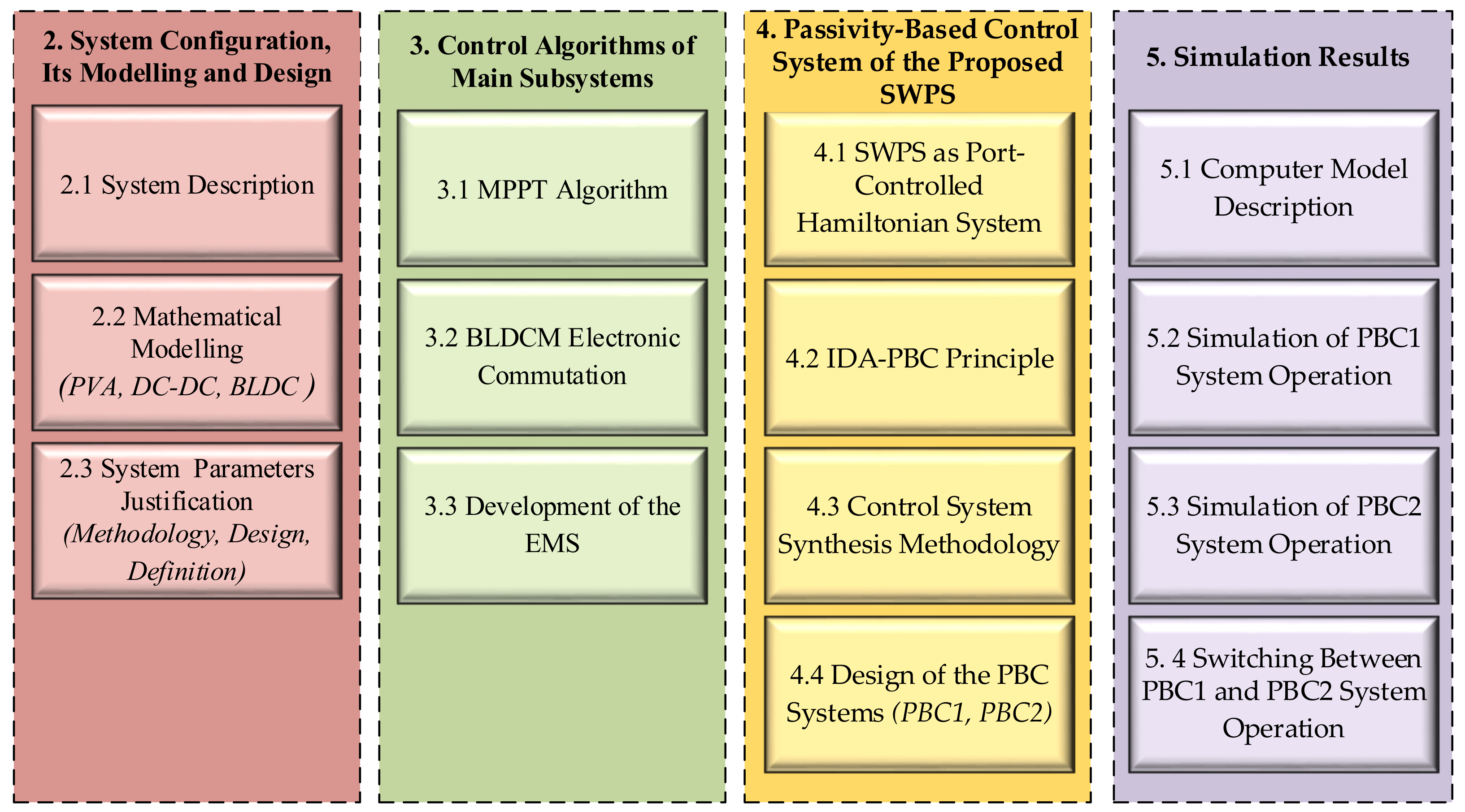
This paper is organized as follows (Figure 1). Section 2 describes the system’s configuration and highlights the mathematical modelling and design of its main components. The control algorithms of the main subsystems and EMS of the whole SWPS are presented in Section 3. In Section 4, we explain the PBC system synthesis. The simulation results are presented in Section 5. Our conclusions are in Section 6.
2. System Configuration, Its Modelling and Design
2.1. Proposed System Description
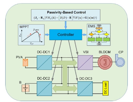
The configuration of the proposed SWPS is presented in Figure 2. The power supply in the system is a PVA of the voltage vpv. The MPPT of the PVA is provided by a boost DC–DC converter DC–DC1, at the output of which the intermediate DC bus voltage vint is formed. All the other devices are connected to the intermediate DC bus: (1) a BLDCM through a voltage source inverter VSI composed of six switches, which performs an electronic commutation of a machine armature winding; (2) a battery B with the voltage vb through a bidirectional DC–DC converter DC–DC2; and (3) an external DC load through a buck DC–DC converter DC–DC3. At the output of the latter, the DC bus voltage vdc is formed, which can also supply AC consumers through an additional DC–AC converter (not shown in Figure 2). A centrifugal water pump CP is coupled to a shaft of the BLDCM.
The advantage of the proposed SWPS configuration is that the voltages of the PVA and the battery can be significantly lower than the intermediate DC bus voltage, which is required to supply the BLDCM of enough high power. That is due to the boost type of the converters DC–DC1 and DC–DC2. This allows a smaller number of PV modules and battery cells to be connected in series, which increases the security of the PVA and the battery, as well as simplifying the battery management system. The output DC bus voltage must correspond to the voltage of the DC consumers or the input voltage of a transformer-less inverter for the AC consumers. For single-phase AC consumers with an operating voltage of 230 V, the DC voltage must be at least 320 V. Therefore, the following relations are valid for this SWPS configuration:
Capacitors in the intermediate and output DC buses, Cint and Cdc, respectively, reduce the voltage pulsations in these buses, which are generated by the pulse operation of the DC–DC converters and the VSI.
The current ipv generated by the PVA and the current iload external electrical consumption are the two main disturbances of the SWPS. The voltages vint and vdc are the controlled variables. The value of vint directly affects the DC current im of the VSI consumption and the CP angular velocity because the VSI mostly works without PWM, providing only positional low-frequency switching of the BLDCM armature winding. PWM motor voltage control is used only for its smooth start-up.
2.2. Mathematical Modelling of Main System Components
2.2.1. PVA Modelling
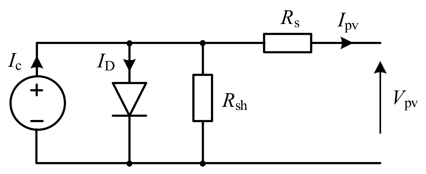
The most common mathematical model of a PV module is obtained from the equivalent circuit of a PV solar cell, shown in Figure 3. In this model circuit, Ic is the photo-current generated by the PV cell depending on the solar irradiation and cell temperature and Rs and Rsh are the series and shunt internal resistances of the cell.
Using the equivalent circuit in Figure 2, the nonlinear V–I characteristic of the PV solar cell is [8]:
where I0 is the reverse saturation current of a diode, q is the electron charge, k is the Boltzmann constant, and T is the operating cell temperature in Kelvin.
Because the PV solar cell voltage is about 0.5 V, in order to obtain more voltage and power in a PV module, several dozen PV solar cells are connected in series. To compose the PVA, a number of the PV modules are already connected in series, forming a PV string; some of these PV strings may be connected in parallel.
2.2.2. DC–DC Converter Modelling
The converters DC–DC1, DC–DC2 and DC–DC3, which are used in the proposed SWPS (see Figure 2), operate in pulsing mode. However, in the case of continuous currents in inductors and voltages in capacitors, as shown in [30], it is possible to use with reasonable accuracy the average model of DC–DC converters. Under these conditions, the duty ratio D, which truly acts as an external control input to the average PWM model of a converter, is used. Since the voltage gain in the boost DC–DC converter is (1 − D)−1, the factor of conversion of the output voltage to the input of such converter is (1 − D). The same factor is used to convert the input current of the boost DC–DC converter to its output. Taking this into account, we can write voltage balance equations in the input of each of three DC–DC converters, from which the equations of the current dynamics in the circuits of the PVA, the battery, and the external load can be written as
where the subscript i displays the relationship to the PVA, or to the battery, or to the external load.
Because the converters DC–DC1, DC–DC2 and DC–DC3 are jointly connected from the higher voltage side, we can compose the current balance equation for the intermediate DC bus, from which the voltage vint dynamics can be described by the following equation:
where D1, D2 and D3 are the duty ratios of the converters DC–DC1, DC–DC2, and DC–DC3, respectively, while ipv, ib and iload are the currents of the PVA, the battery, and the external load, respectively.
2.2.3. Mathematical Model of BLDC Motor
For the mathematical model, we accept the following assumptions: the armature winding is symmetrical; the active resistance of the armature winding possesses a constant value; phase electromotive forces (EMF) feature a trapezoidal shape, with a maximum width of 120° el.; and losses in steel and magnetic saturation are neglected. Consequently, the equilibrium voltages in the three phase circuits of the armature winding are described by the vector-matrix equation:
where , and are the vector-columns of the phase voltages, currents and back-EMFs, respectively, R is the diagonal matrix of three identical active resistances R of the phase windings and L is the matrix composed diagonally of the phase winding self-inductances and filled in the remaining cells with mutual interphase inductances M.
Given that the sum of currents in the three star-connected phases of the machine is zero, the dynamic equations of a BLDC motor obtaining from Equation (5) may be expressed in matrix form as in [31]:
The back-EMFs of each phase in Equation (6) should be as follows, in accordance with [18]:
where Kω is the back-EMF constant, θe is the electrical rotor angle and ω is the angular velocity of the motor.
The value θe is p times larger than the real rotor angle θm, where p is the number of pole pair, and can be defined from the following equation:
The function f(θe) gives the trapezoidal waveform and one period of this function can be written as
The electromagnetic torque of the motor is given by the expression
where is the dot product of the back-EMF and armature current vectors.
For a single-mass mechanical drive system with the total moment of inertia JΣ reduced to the motor shaft, the equation of motion features the form
where TL is the load torque of the drive and B is the dumping coefficient.
2.2.4. Mathematical Model of Centrifugal Pump
2.3. Justification of System Components Parameters
2.3.1. Development of a Methodology for Parameter Justification
Neglecting losses in DC–DC converters, we can describe the next general power balance equation:
where ppv is the power generated by the PVA, pVSI is the power on the input of the VSI, pb is the battery charge or discharge power and pload is the power of the external load. In different operating modes, any of the powers in Equation (13) can feature zero value.
In Equation (13), ppv and pload are external random power perturbations, pVSI is unregulated power consumption by the BLDCM with the pump, and pb is power balancing. Balance Equation (13) is the basis for substantiating the parameters of the studied configuration of the SWPS. We propose the following methodology of this justification, which is based on the p.u. values of the main system parameters.
For the maximum p.u. value of the PVA-generated power p*PV.max = 1, the maximum p.u. value of the intermediate voltage v*int = 1. The BLDCM should be chosen for this power and voltage. For the power of the external load, it is necessary to decide on a part of the maximum PVA generated power kload, which can be directed from the intermediate DC bus to the external load. The pump consumes the remaining (1 − kload) part of power. Since the angular velocity of the BLDCM is directly proportional to the DC voltage of its supply, i.e., vint and the pump power is proportional to the cube of the angular velocity Equation (12), the p.u. voltage of the intermediate DC bus, for maximum irradiation and maximum external power consumption will be
The value of v*int obtained from Equation (14) should be taken as a reference value for the control system of the intermediate DC bus voltage V*int, which is ensured by the converter DC–DC2. Consequently, in the power balance Equation (13), pVSI = const and is determined by the voltage V*int. With a decrease in external power consumption and a high level of irradiation, the rest of the power generated by the PVA is used to charge the battery, and in the case of reduced irradiation and high external load, the battery provides the external consumer with insufficient power. In order to reduce energy losses in the DC–DC3 converter, it is advisable that in this mode it is fully switched on, i.e., D3 = 1. Consequently, v*dc = v*int.
In the case of a high level of irradiation and a fully charged battery, the DC–DC2 converter must be switched off and in Equation (13), pB = 0. In this case, the intermediate DC bus voltage is no longer automatically regulated and increases to a value that provides a balance between power generation ppv and its consumption pVSI + pload. Since v*int is greater than V*int, the converter DC–DC3 must operate in the mode of voltage regulation of the external DC bus at the level V*dc = V*int.
Based on the above, the sequence for determining the parameters of the proposed configuration of SWPS should be as follows:
- 1)
- Set the desired value of kload and determine by Equation (14) V*int, which also corresponds to V*dc.
- 2)
- Set the required absolute value of Vdc and determine the absolute value of Vint.max = Vdc/V*dc.
- 3)
- For the specified rated parameters of the centrifugal pump (power PCP and angular velocity ωCP), as well as obtained in paragraph 2 the nominal DC voltage of the inverter VDC.VSI.n = Vint.max, select or design the appropriate BLDCM.
- 4)
- Find the nominal parameters of the PVA: choose the rated voltage from the range of VPVA.n = (0.30–0.35)Vint.max and the rated power of PPVA.n = (1.15–1.20)PCP.
- 5)
- Form the PVA from PV panels of the selected type, determining the required number of panels connected in series in the string and the number of strings connected in parallel.
- 6)
- Find the nominal parameters of the battery: choose the voltage from the range of VBb.n = (0.25–0.35)Vint.max. The required battery capacity depends on factors such as the average annual insolation level and set indexes of water deficiency and power supply probability.
2.3.2. Design of the Studied SWPS
We apply the proposed technique to determine the parameters of the studied SWPS of the proposed configuration. For this study, we took kload = 0.4 and obtained from Equation (14) V*int = V*dc = 0.843. Assuming Vdc = 320 V, we obtained Vint.max = 379.6 V. The rated parameters of the centrifugal pump in the studied SWPS were chosen as follows: PCP.n = 2.7 kW and ωCP.n = 314 s−1. According to Equation (9), for such a pump, kω = 8.72·10−5 W·s3. For such mechanical parameters of the drive object and VDC.VSI.n = 380 V, the BLDCM was designed. The parameters are presented in Table 1.
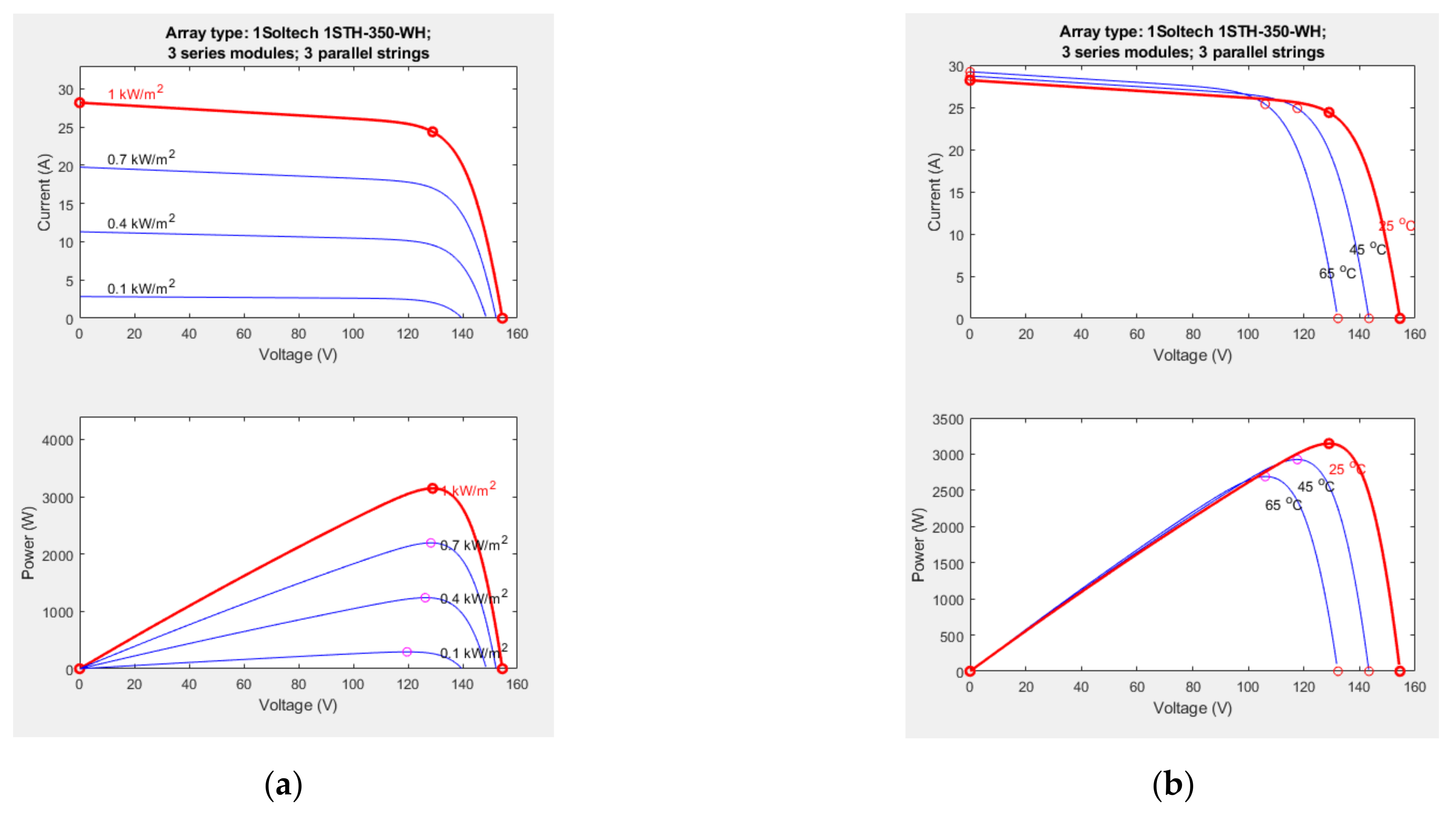
In accordance with paragraph 4 of the above sequence of parameter determination, the rated parameters of the PVA should be within the following limits: VPVA.n = (114–133) V and PPVA.n = (3.105–3.24) kW. The results of the analysis of the parameters of the PV panels offered on the market demonstrated that PVA with these parameters could be well compiled from the PV modules of 1Soltech 1CTH-350-WH, whose parameters are presented in Table 2. The studied PVA should consist of nine specified PV modules. Three should be connected in parallel strings, in each of which three PV modules are connected in series. The rated parameters of the PVA arranged in this way are VPVA.n = 129 V, PPVA.n = 3.15 kW. In the Matlab/Simulink (MathWorks, Natick, MA, USA) environment, a virtual PVA model was developed that can be composed of a given number of specific PV panels, each of which is modeled according to the equivalent circuit of PV solar cell presented in Figure 3. Figure 4 presents the current and power dependences of the studied PVA from its voltage in different conditions, for the solar irradiation levels of 0.1, 0.4. 0.7 and 1.0 kW/m2 at the same PVA temperature of 25 °C (Figure 4a) and the temperature levels of 25, 45 and 65 °C at the same solar irradiation of 1.0 kW/m2. All of these data were obtained from Matlab/Simulink (MathWorks, Natick, MA, USA). The obtained curves display the dependences of the magnitude and the parameters of the V–I-characteristic from both the solar irradiation level and the temperature of solar panels of the PVA. The operation of the PVA in a maximum power point (MPP) is achieved by means of regulating the PVA load through the MPPT controlling converter DC–DC1.
According to paragraph 6 of the above sequence, the nominal voltage of the battery should be in the range of VB.n = (95–133) V. An inexpensive battery with this voltage can be made of two series lithium-ion batteries, BYD Battery-Box LV, with a voltage of 48 V and an energy capacity of 3.5 kWh [33]. The capacity of such a battery is about 73 Ah, which can comfortably fulfil the energy needs of the studied SWPS.
2.3.3. Determination of the Passive Components’ Parameters
Based on [17,18,34], the parameters of the passive elements were determined: the inductance of inductors and capacitances of capacitors, which are part of three DC–DC converters. Calculations were performed for the maximum power mode. The PWM frequency value was chosen to be f = 20 kHz. The relative pulsation of a current δI in the inductors was set at the level of 10%, but the relative pulsation of the voltage δV in the capacitors was set at the level of 1% because the control system uses voltage feedback.
- For the boost converter DC–DC1:
The duty ratio for the converter DC–DC1 is
The inductance of the input inductor L1 should be not less than
The capacitance of the output capacitor C1 should be not less than
where i1out.max = PPVA.n/Vint = 3150/320 = 9.84 A is the output current of the DC–DC1 converter at maximum irradiation.
However, in addition to DC–DC1, the VSI of the BLDCM also affects the voltage ripple in the intermediate DC bus to which the capacitor C1 is connected. The based angular frequency of the BLDCM is ωn = ωBLDCM.n Pp = 314·2 = 624 rad/s, where Pp is the number of pole pairs.
The necessary value of the capacitance of the capacitor C1 to reduce the voltage ripple δV at 1% due to operation of the BLDCM with six-step switching of the armature winding must be at least
where iVSI.max = PVSI.n/vint.max = 3000/380 = 7.89 A is the input current of the VSI at maximum irradiation.
- For the buck converter DC–DC3:
The duty ratio for the converter DC–DC1 is
The inductance of the output inductor L3 should be not less than
where idc.max = kload PVSI.n/V*int = 0.4·3000/320 = 3.75 A is the maximum value of the external load current.
The capacitance of the output capacitor C3 should be not less than
- For the bidirectional buck-boost converter DC–DC2:
The duty ratio for the converter DC–DC2 is
The inductance of the output inductor L2 should be not less than
where iB.max = idc.max/D3 = 3.72/0.3 = 12.4 A is the maximum value of battery current in the case of maximum solar irradiation and disconnection of external electrical consumption.
The capacitance of the capacitor C3 should be not less than
According to the results of Equations (15)–(24) the parameters of inductors and capacitors for the DC–DC converters of the studied SWPS are selected, which are given in Table 3.
3. Control Algorithms of Main Subsystems
3.1. MPPT Algorithm
In this work, for the production of an MPPT in order to operate the PVA at its optimum operating point, the IC algorithm is used, as in the vast majority of other studies [4,5,6,7,8,11,13]. This method directly uses a duty ratio as a controlling parameter. Direct duty ratio perturbation offers very good stability characteristics and high efficiency of energy utilization due to the low impact of noise and the absence of oscillation [3]. Moreover, higher perturbation rates up to the PWM rate can be used without losing the overall stability of the system [11].
The IC MPPT algorithm uses the voltage and current as feedback from the PVA and generates an optimum value of the duty ratio D. Further, it generates an actual switching pulse by comparing the duty ratio with a high-frequency carrier wave. The direction of perturbation is based on a slope dPpv/dVpv of a Ppv − Vpv curve, as shown in Figure 5: the slope is zero at the MPP, positive on the left, and negative on the right of the MPP. Thus, the IC MPPT algorithm determines the current value of the slop and sets based on its sign the task to change the duty ratio.
To determine the sign of the slop, in the IC MPPT algorithm, no power is used, only the increments ΔV, ΔI and the absolute values V, I of the voltage and the current of the operating point of the PVA, according to the next dependences [11,13]:
After determining the current PVA operating point according to the inequalities shown in Equation (25), the small value of the duty ratio perturbation step ΔD is added or subtracted from the current value of the duty ratio D, as seen from the right part of Equation (25). Ideally, the perturbation stops once the operating point reaches the MPP. However, in practice, the operating point oscillates around the MPP. As the perturbation size reduces, the controller takes more time to track the MPP of the PVA. In this study, the optimum value of the duty ratio perturbation step ΔD = 0.001 was chosen, which minimizes oscillations around the MPP.
3.2. BLDCM Electronic Commutation
The BLDCM is driven by the three-phase VSI with a six-step commutation sequence. Three logic signals, h1, h2 and h3, are generated by three inbuilt low-cost Hall sensors according to the rotor position and are then converted, by a decoder circuit, into the six switching pulses, S1–S6, to operate the VSI, as shown in Table 4 [11,35]. The VSI switches are commutated every 60 degrees, working in a 120° el. conduction mode of operation and only two switches conduct at a time that reduces conduction losses. For an even greater reduction in the amount of losses in the VSI and motor, electronic commutation of the BLDCM was carried out at fundamental frequency switching. In this case, the angular velocity of the motor will be directly proportional to the intermediate DC voltage vint.
3.3. Development of the EMS
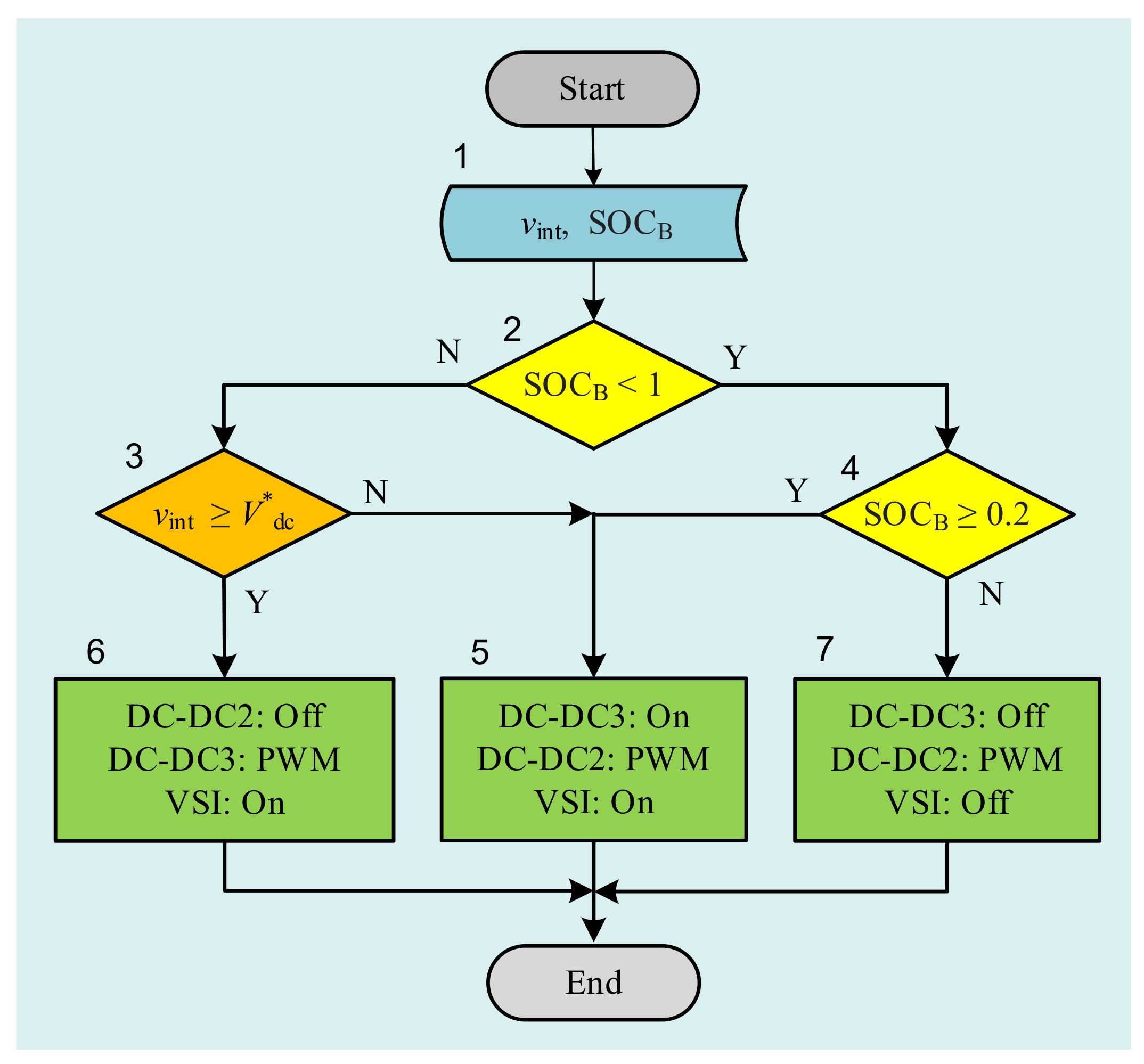
Based on the features of the studied SWPS of the proposed structure, covered in Section 2.3.1, an EMS algorithm, which is shown in Figure 6, was developed. The input information for the EMS are the current measured values of the intermediate voltage vint and the SOC of the battery SOCB (block 1). The SOCB value is calculated by the controller based on signals from a battery current sensor using a special program, which is based on known algorithms and is not considered in this paper. The EMS algorithm works as follows:
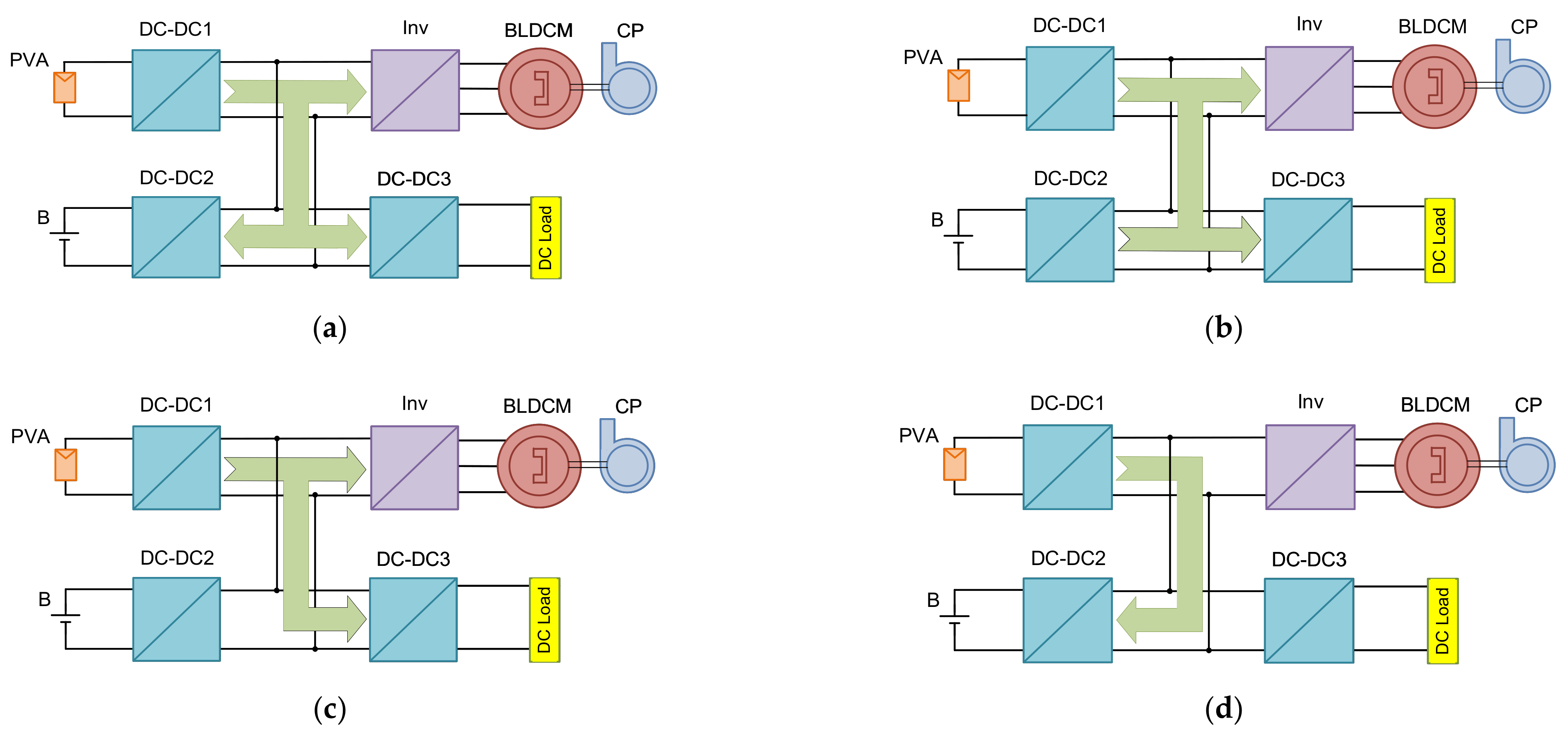
If the battery is not yet fully charged (Y in block 2) and not fully discharged (Y in block 4), then the tasks presented in block 5 are performed, and the power flows in the SWPS are depicted in Figure 7a,b. In particular, the bidirectional DC–DC2 converter provides PWM regulation of the intermediate DC bus voltage at a given level V*int = 320 V, directing the excess power of the generated PVA electricity to the battery (Figure 7a) or supplying the missing power to the intermediate DC bus from the battery (Figure 7b). Herewith, the DC–DC3 converter is “On” and V*dc = V*int = 320 V.
If the battery is already fully charged (N in block 2), in block 3, the vint is compared with the reference voltage of the DC bus for external power supply V*dc. The result of this comparison provides integral information about the current level of irradiation (generated by the PVA power) and the value of the external power consumption. If the generated power is high and the external power consumption is low, then vint is high (Y in block 3) and the tasks shown in block 6 are performed. The power flows in the SWPS are depicted in Figure 7c. In particular, the DC–DC2 converter is “Off”, and the intermediate DC bus voltage, depending on the level of solar irradiation and the external power consumption, is in the range from V*int = 320 V to vint.max = 380 V. The buck DC–DC3 converter provides PWM regulation of the external DC bus voltage at a given level of V*dc = 320 V.
In these two cases, the VSI can be on if it is a demand to power the CP by the BLDCM.
If the battery is already fully discharged (N in block 4), then the tasks displayed in block 7 are performed; the power flows in the SWPS are depicted in Figure 7d. In particular, both consumers of generated electricity are turned off: the VSI turns off BLDCM with the CP and the DC–DC3 converter—the external consumer. Next, the bidirectional DC–DC2 converter provides PWM regulation of the intermediate DC bus voltage at a given level of V*int.min = v*int·vint.max = 0.11/3·380 = 0.464·380 = 176 V, which corresponds to the minimum level of solar radiation (p*pv = 0.1). In this case, all the generated PVA power is used to charge the battery.
If, in the case of a fully charged battery (N in block 2), the generated power is low and/or the external power consumption is high (N in block 3), then the tasks presented in block 5 are performed too. In this case, the power flows in the SWPS are depicted in Figure 7b. This is because, under these conditions, the battery is switched to discharge mode.
As can be seen in the described EMS algorithm, in the studied SWPS of the proposed structure, at any given time, only one of the DC–DC converters operates in PWM control mode, and the other is either “On” or “Off”. This reduces the switching energy losses in the converters, helping to increase the efficiency of the entire SWPS.
4. Passivity-Based Control System of the Proposed SWPS
4.1. SWPS as Port-Controlled Hamiltonian System
One of the most fundamental approaches in the PBC system synthesis procedure is to consider a controlled object as a port -controlled Hamiltonian (PCH) system [22,23,24,25,26,27]:
where x(t) ϵ ℝn is the state variables vector, J(x) ϵ ℝn x n is the skew-symmetric matrix of interconnections, R(x) ϵ ℝn x n is the semi-definite symmetric damping matrix, H(x) is the Hamiltonian function, D ϵ ℝn x n is the diagonal matrix of inertias, G(x) ϵ ℝn is the input ports matrix and u(t) ϵ ℝn is the vector consisting of the input energy variables of the system.
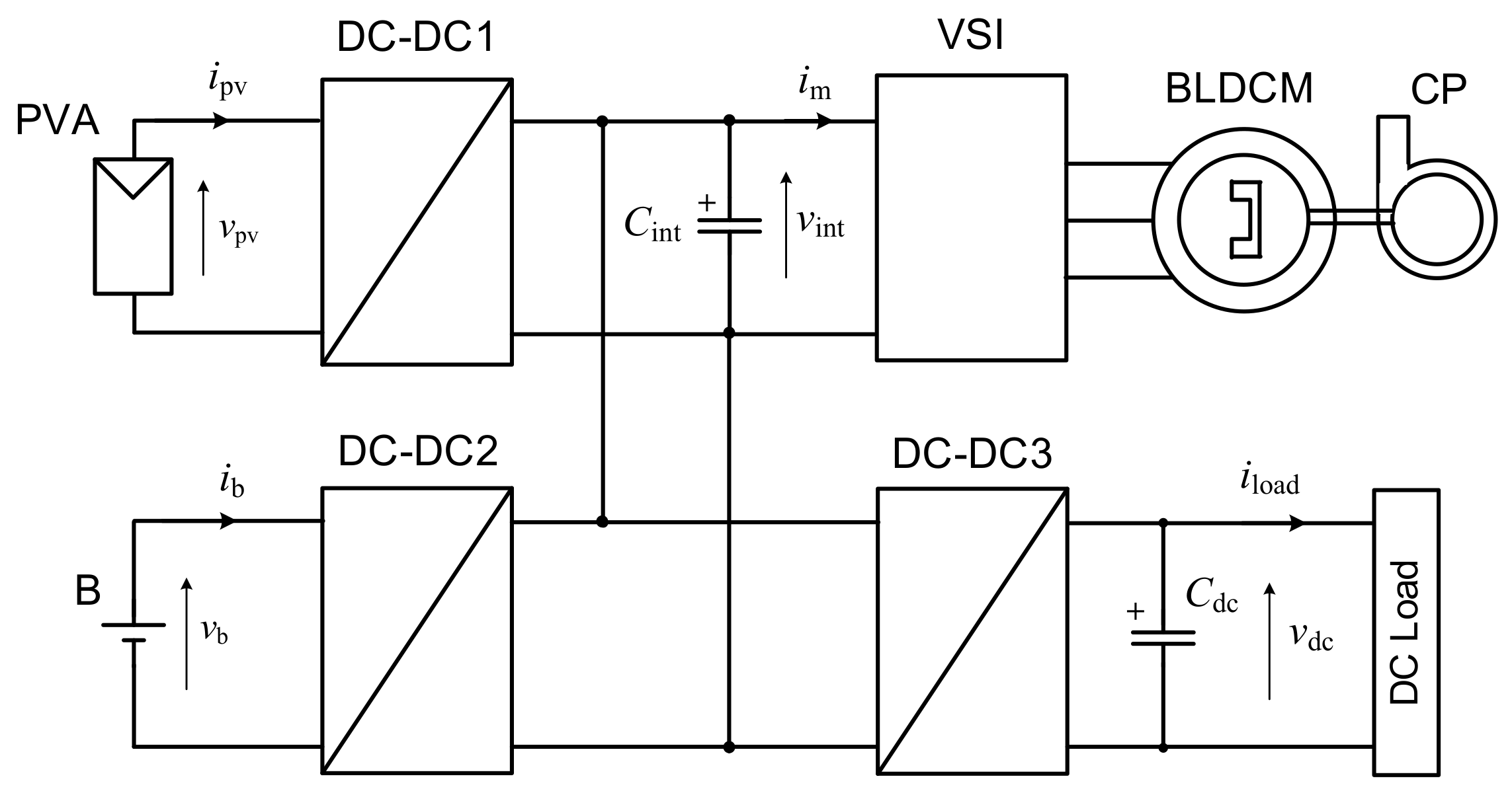
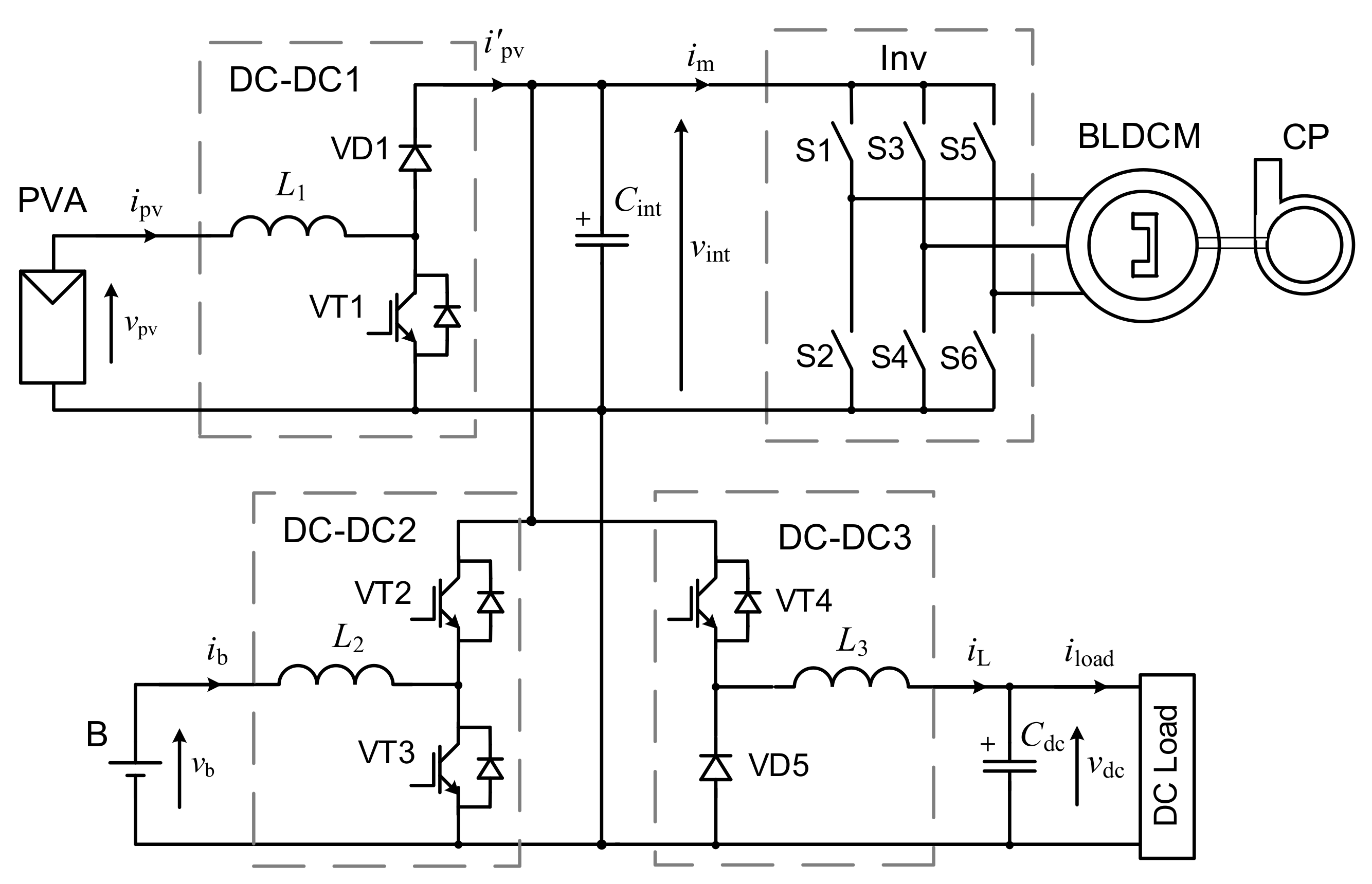
According to the structure presented in Figure 1, an electric scheme of the proposed SWPS is presented in Figure 8.
Based on Equations (3)–(5) from Section 2.2, we can create the following system of differential equations that describe the studied SWPS operation:
From Equation (27), it can be seen that the energy storage devices in the SWPS can be defined as follows: the motor windings (in general represented as Lm), related to the energy pulse in them, Lm im; the capacitors Cdc and Cint with energy pulses Cdc, vdc and Cint vint; the inductors in DC–DC2 and DC–DC3 — L2 and L3 with respective energy pulses, L2 ib and L3 iL. Thus, the following vectors of the state and port variables can be chosen:
where .
The total energy (Hamiltonian) of the SWPS is as follows:
Based on Equation (29), the vector of Hamiltonian partial derivatives by the state variables can be defined as follows:
Based on Equation (27), the matrices of the SWPS structure (interconnection and damping) in the form of PCH system Equation (26) will appear as follows:
The port matrix of the SWPS system in PCH form is G = I, where I is the diagonal unit matrix.
4.2. IDA-PBC Principle
The main approach to creating a PBC system for the PCH system is the IDA [29]. According to this approach, the control system forms a new desired total energy function Hd through additional interconnections and damping impacts. It reaches its minimum in equilibrium point in a closed-loop system and determines the behavior of the system in both steady and transitional states. This equilibrium point is defined by the reference signal. The desired energy function Hd is
where defines the error between the state vector x and equilibrium point .
Based on [27], the dynamics of the closed-loop system can be described as the following equation:
where Jd = J + Ja, Rd = R + Ra, Ja(ji,k) and Ra(ri,k) are the interconnection and damping matrices of the control system and i and k are the row and column numbers.
For Equation (30), according to [35], we can receive the following statement:
which means that the closed-loop system, Equation (33), is asymptotically stable.
4.3. Control System Synthesis Methodology
By equating the right-hand sides of Equation (26) and Equation (33), we obtain the following synthesis equation:
where the following values can be found from Equations (28) and (31)
Substituting Equation (36) into Equation (35), the final matrix equation of IDA-PBC synthesis procedure is:
where Dk are the duty ratios of the DC–DC converters and k = 1, 2 and 3.
According to the described steps, a program for the automated synthesis of a PBC system based on the IDA-PBC approach was designed in the MathCAD environment [36]. As inputs for the program, the matrices of the controlled object in PCH representation (x, J, R, D, G(x) and u), as well as the structure of control system (Ja and Ra) and desired equilibrium state () were used. The outcome of the program is a symbolic solution to Equation (34) in the form of desired control actions (for this case, the expressions of the desired Dk and ), which can be utilized for building/programming controllers. This program can be used for systems of different natures and different orders. The program makes it possible to quickly check the different structures of control influence formers (CIF) with different combinations of control system parameters and to analyze their potential.
Based on this methodology, two PBC systems were synthesized corresponding to the work of the proposed SWPS in the modes represented by blocks 5 and 7 from the EMS Algorithm (see Figure 5). These PBC systems are denoted as PBC1 for mode 5 and PBC2 for mode 7.
4.4. Design of the PBC Systems
4.4.1. PBC1 System
In the case of mode 5, DC–DC3 is always “On”, which means D3 = 0 in Equation (27), and we can control our system only by changing D2. The general structure of the system remains; the only change in PCH form is that now j14 = 1 and j41 = −1. Th next step is to use the described procedure of IDA-PBC to synthesize CIFs for the PBC1.
For all the zero elements of the control matrices Ja = 0 and Ra = 0, substituting all matrixes into Equation (37), we receive the following system of equations:
where , , , , and K = const.
Solving Equation (38) with the designed program, we obtained the simplest control law CIF5.0:
Instead of selecting Ja = 0 and Ra = 0, different parameters of control matrices can be chosen as non-zero. This may lead to different structures of CIF, with different possibilities. In order to analyze potential optimal combination of control parameters, a set of analyses were conducted.
As one of the best, the following structure of control system matrixes was obtained:
where j13 and r33 are the parameters of additional interconnection and damping that are used as settings.
In this case, the system of Equation (38) is more complex and we obtained a more extended control law CIF5.1 for structure (40):
4.4.2. PBC2 System
In the case of mode 7, the DC–DC2 is always “Off”, which means that D2 = 1 in Equation (27); we can control our system only through the regulation of D3. In this mode, we can completely neglect the third equation of the system in Equation (27). For all the zero elements of the control matrices Ja = 0 and Ra = 0, according to described synthesis procedure, substituting all the matrices into Equation (37) results in the following system of equations:
where , , and .
Solving Equation (42) with the designed program, we obtained the simplest control law CIF7.0:
Instead of selecting Ja = 0 and Ra = 0, different parameters of control matrices can be chosen as non-zero. This may lead to different structures of CIF, with different possibilities. In order to analyze a potential optimal combination of control parameters, a set of analyses were conducted.
As one of the best, the following structures of control system matrices were obtained:
where j34 and r33 are the parameters of additional interconnection and damping, which are used as settings.
In this case, the system of Equation (42) is more complex and we obtained a more extended control law CIF7.1 for structure (45):
5. Simulation Results
5.1. Computer Model Description
In order to study the work regularities of the investigated structure of SWPS and to evaluate the efficiency of the obtained control laws in Equations (39), (41), (43) and (45), we conducted a computer simulation of the synthesized PBC systems at solar irradiation and electrical load changing in MATLAB/Simulink.
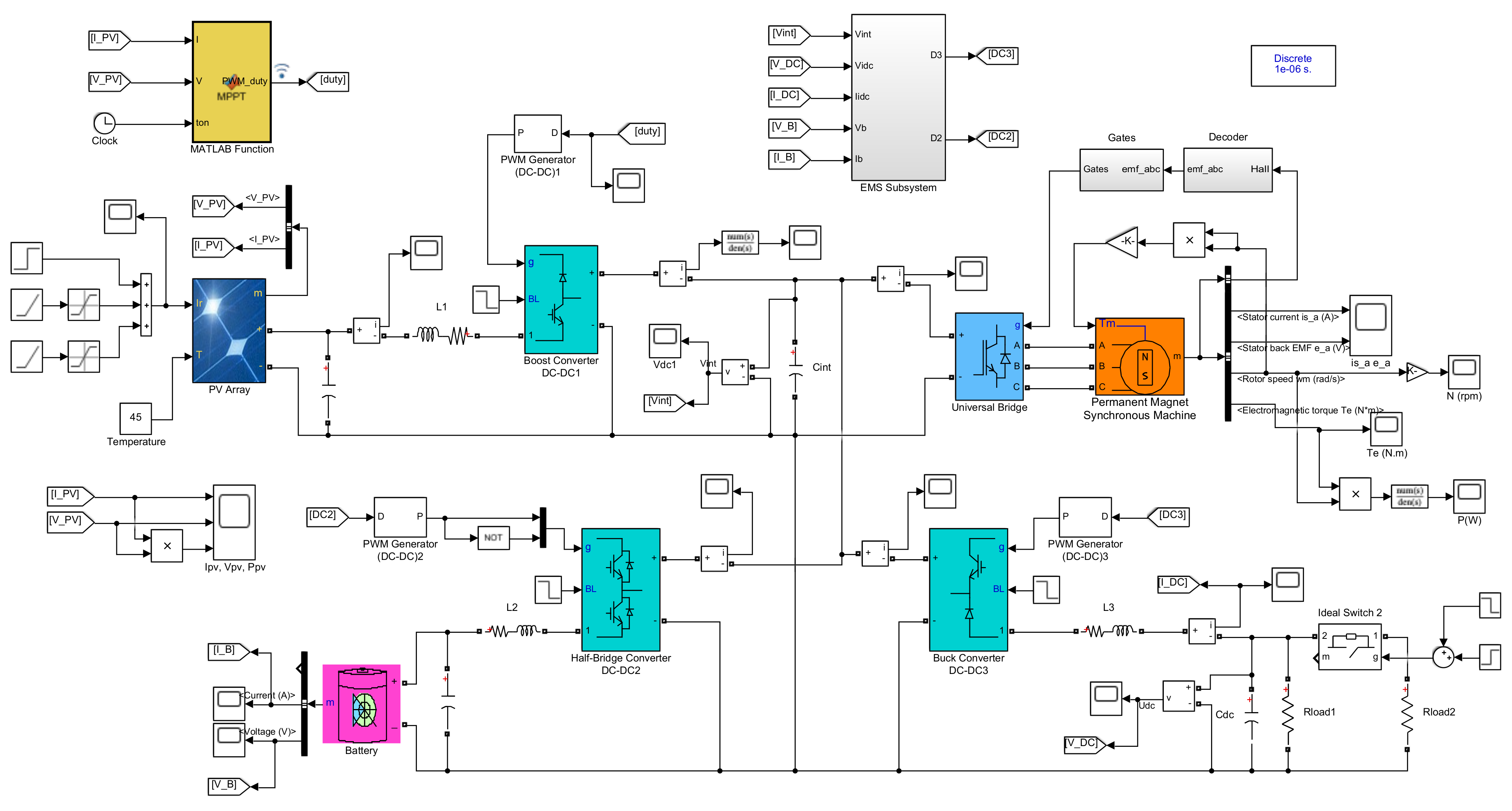
Figure 9 presents the created computer model of the studied system, in which virtual blocks available in the Simscape library are used maximally, in particular: PV Array, Battery, Permanent Magnet Synchronous Machine, DC–DC Converter, Universal Bridge, PWM Generator (DC–DC), Decoder, Gates, etc. For modeling the work of all three DC–DC converters, a detailed model is used that most accurately describes the operation of a real pulse converter. The control functions are input into the block MATLAB Function, where the program of IC MPPT algorithm is written, and the EMS Subsystem, where the algorithm of EMS is realized.
The conducted simulations demonstrate that the simplest control laws realized by the CIF5.0 Equation (39) for the control of the DC–DC2 converter and by the CIF7.0 Equation (43) for control of the DC–DC3 converter generally cope well with the tasks assigned to them. However, in perturbation modes, the system dynamics are uncontrolled; this is manifested in excessive oscillations in the basic system variables. The introduction of the damping coefficient r33 to the CIF5.1 Equation (41) and to the CIF7.1 Equation (45) provides good damping of these oscillations. However, the greater the damping introduced, the greater the static error of the adjustable coordinate, namely vint for the CIF5.1 and vdc for the CIF7.1. The task of compensating for these static errors is performed by the second additions in the right parts of these CIFs, which are due to the introduction of interconnection coefficients, namely j13 in the PBC1 and j34 in the PBC2. To obtain a compromise between statics and dynamics in the synthesized PBC systems, it is necessary to select the optimal ratios between the values of the introduced interconnection and damping coefficients for each of the systems. According to the research results, the following optimal values of these coefficients were chosen: j13 = 5, j34 = 5, r33 = 1.
5.2. Simulation of PBC1 System Operation
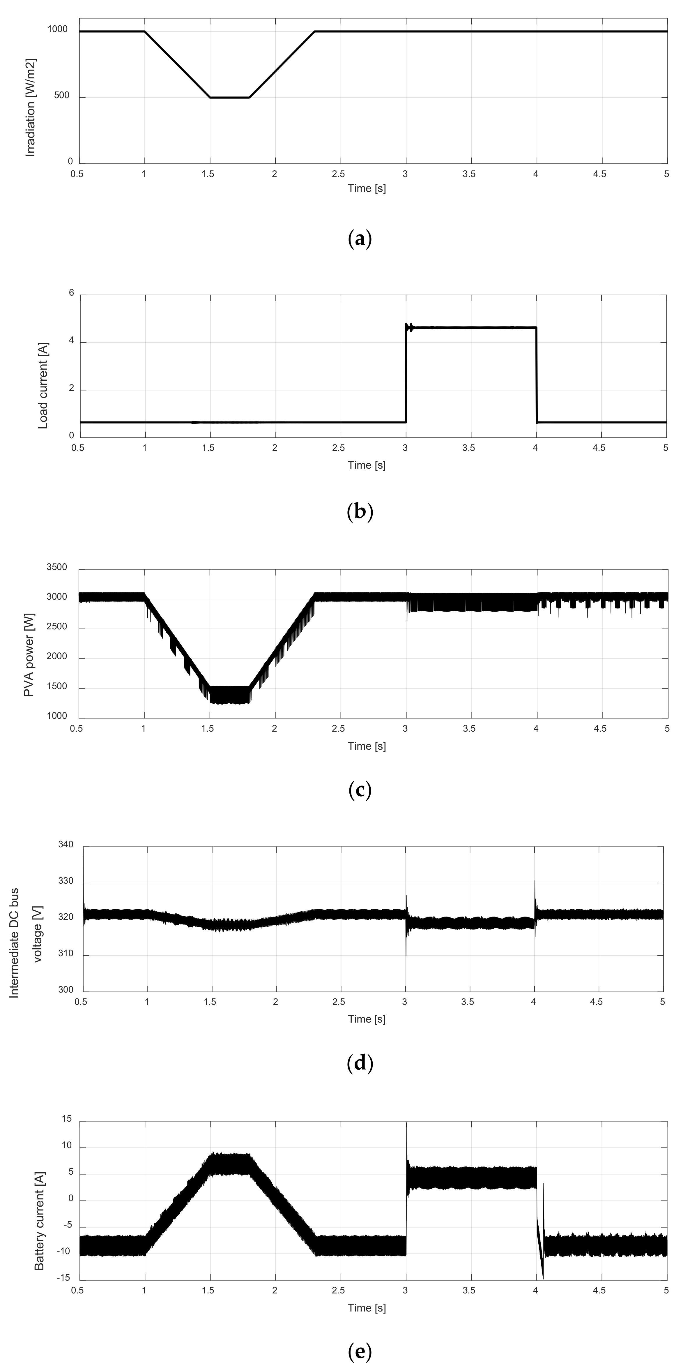
As demonstrated in Section 3.3, the PBC1 system operates with a partially charged battery. In this case, the power exchange between the intermediate DC bus and the battery stabilizes the voltage vint by controlling the DC–DC2 converter (see Figure 7a,b). The waveforms in Figure 10 obtained from the computer simulation illustrate the operation of the studied SWPS in this mode.
The main perturbations are modeled as a change in the solar irradiation with a real speed of 100 W/m2/s (Figure 10a) and as an abrupt change of the load current consumed from the DC bus (Figure 10b). Figure 10c demonstrates the satisfactory performance of the IC MPPT. The operation of the PBC1 system is illustrated by the waveforms in Figure 10d,e. By adjusting the battery current in both charging (Figure 7a) and discharging (Figure 7b) modes, the DC–DC2 controller maintains the voltage vint at a reference level of 320 V with an error of no more than 1% in static modes and about 3% in dynamic modes. On the DC bus, the dynamic error reaches 10% (Figure 10f). This is due to the purely active load of this network, which does not limit the rate of change of the load current. The mechanical power transmitted from the BLDCM to the CP also varies very little, as the motor is powered by an almost constant voltage vint (Figure 10g).
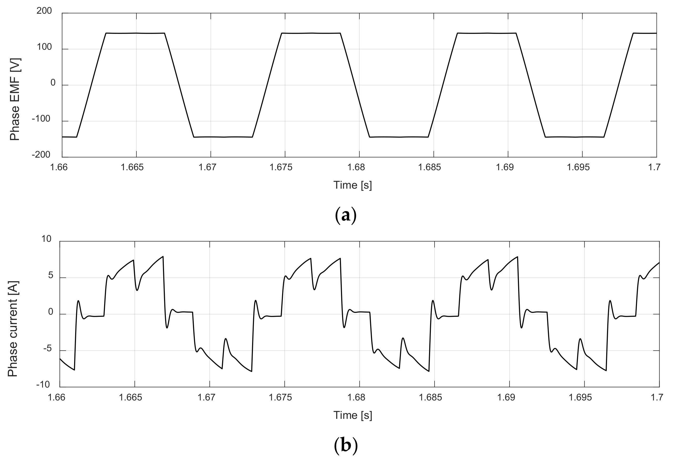
Figure 11 represents the shapes of the EMF and current in one phase of the motor, which displays the correct operation of the BLDC drive.
5.3. Simulation of PBC2 System Operation
The PBC2 system operates on a fully charged and unplugged battery, as demonstrated in Figure 7c. The solar irradiation must be high enough and the DC bus load low enough to prevent the intermediate DC bus voltage from decreasing lower than 320 V. These conditions were modeled by the corresponding external influences displayed in Figure 12a,b, and the waveform vint obtained under these conditions is shown in Figure 12c. The DC–DC3 converter lowers the voltage vint and stabilizes the DC bus voltage vdc at the level of 320 V, with practically no static error and with a dynamic error not exceeding 2% (Figure 12d). The power transmitted to the CP fluctuates according to changes in vint (Figure 12e).
5.4. Switching between PBC1 and PBC2 System Operation
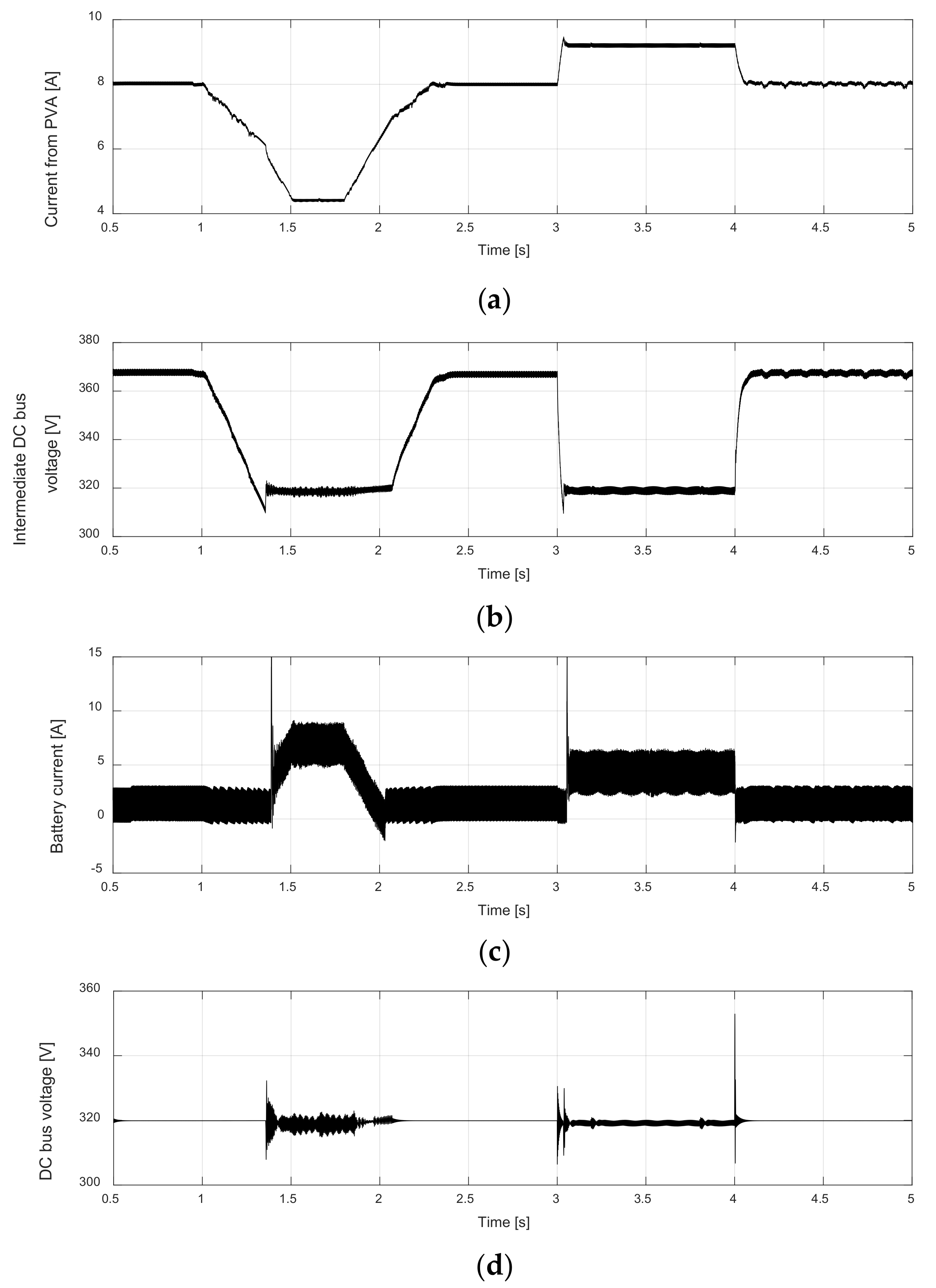
If, during the operation of the studied SWPS as the PBC2 system, solar irradiation decreases, and/or the load of the DC bus increases to such a level that the intermediate DC bus voltage falls below 320 V, then, according to the EMS algorithm displayed in Figure 5, the PBC1 system should switch to operation instead of the PBC2. The time dependences of the main variables in the studied SWPS for such switches between the mode PBC1, illustrated by Figure 6, and the mode PBC2, illustrated by Figure 7c, are displayed in Figure 13. The waveforms of the maim perturbation for this case are the same as in Figure 10a,b. The PVA generates power as shown in Figure 10c, and the current moving from the DC–DC1 converter to the intermediate DC bus features the time dependence presented in Figure 13a. From the waveform of the intermediate DC bus voltage (Figure 13b), it can be seen that in the time intervals of 1.35–2.1 s, when solar irradiation is significantly reduced, and 3–4 s, when a load of the DC bus increased, the mode PBC2 switched to the mode PBC1. At this time, the fully charged battery discharged, as was clearly visible from the waveform of the battery current (Figure 13c). Depending on the operating mode, the output voltage of the DC bus was stabilized at a given level of 320 V by the converter DC–DC3 in the PBC2 mode or the DC–DC2 in the PBC1 mode (Figure 13d).
6. Conclusions
When using the traditional SWPS, the additional functions make it possible to increase the use of solar-generated electricity. However, additional devices or functions require their own automatic control, which must be consistent with the operation of other devices in the system. Energy control principles, in particular the PBC method, are well suited to such complex and, usually, nonlinear MIMO systems. In the studied SWPS with additional functions of generated electric energy storage and power supply of external consumers, the proposed EMS is implemented through the PBC method. The EMS is designed considering an energy-saving, including the work with the PWM of only one of the DC–DC converters in all modes (Figure 7). The developed EMS algorithm includes only two PBC systems, which are switched depending on the degree of battery charge and the current levels of two main disturbances—solar irradiation and electrical consumption. Among the rather large number of possible CIF structures obtained using the authors’ method of structural synthesis, one was found for each PBC system that provides a simple implementation with a minimum number of coordinate sensors, but at the same time insures the necessary static and dynamic control indicators. Thus, we have obtained an error of the intermediate voltage regulation of no more than 1% in static modes and about 3% in dynamic modes. A computer simulation of the entire system in three modes, the PBC1 system, the PBC2 system and their switching, depending on the values of two main perturbations, demonstrated the suitability of the PBC method for the SWPS of the proposed structure and effectiveness of the developed control system.
Author Contributions
Conceptualization, I.S. and M.L.; methodology, I.S. and Y.B.; software, Y.B.; formal analysis, M.L.; investigation, M.L.; writing—original draft preparation, Y.B. and I.S.; writing—review and editing, M.L. and I.S.; supervision, I.S. All authors have read and agreed to the published version of the manuscript.
Funding
This research received no external funding.
Conflicts of Interest
The authors declare no conflict of interest.
References
- Aliyua, M.; Hassana, G.; Saida, S.A.; Siddiquic, M.U.; Alawamid, A.T.; Elamin, I.M. A review of solar-powered water pumping systems. Renew. Sustain. Energy Rev. 2018, 87, 61–76. [Google Scholar] [CrossRef]
- Solomon, Y.; Rao, P.N.; Tadesse, T. A review on solar photovoltaic powered water pumping system for off-grid rural areas for domestic use and irrigation purpose. Int. J. Eng. Res. Technol. (IJERT) 2021, 10, 258–269. [Google Scholar]
- Islam, H.; Mekhilef, S.; Shah, N.B.M.; Soon, T.K.; Seyedmahmousian, M.; Horan, B.; Stojcevski, A. Performance evaluation of maximum power point tracking approaches and photovoltaic systems. Energies 2018, 11, 365. [Google Scholar] [CrossRef] [Green Version]
- Harsh, K.; Pandey, K.; Kumar, R.; Jangir, A.K. BLDC motor driven water pump fed by solar photovoltaic array using boost converter. Int. J. Eng. Res. Technol. (IJERT) 2020, 9, 635–639. [Google Scholar]
- Kumar, R.; Singh, B.; Chandra, A.; Al-Haddad, K. Solar PV array fed water pumping using BLDC motor drive with boost-buck converter. In Proceedings of the 2015 IEEE Energy Conversion Congress and Exposition (ECCE), Montreal, QC, Canada, 20–24 September 2015. [Google Scholar]
- Kumar, R.; Singh, B. Solar PV array fed water pumping system using SEPIC converter based BLDC motor drive. In Proceedings of the 2014 Eighteenth National Power Systems Conference (NPSC), Guwahati, India, 18–20 December 2014; pp. 1–5. [Google Scholar]
- Kumar, R.; Singh, B. BLDC Motor-Driven Solar PV array-fed water pumping system employing Zeta converter. IEEE Trans. Ind. Appl. 2016, 52, 2315–2322. [Google Scholar] [CrossRef]
- Durgaprasad, R.; Guruvulunaidu, P.; Prasad, C. Solar PV array-fed water pumping system using zeta converter based closed-loop control of BLDC motor drive. Int. J. Eng. Res. Technol. (IJERT) 2018, 7, 389–397. [Google Scholar]
- Sharma, V.; Hossain, M.J.; Nawazish Ali, S.M.; Kashif, M. A photovoltaic-fed Z-source inverter motor drive with fault-tolerant capability for rural irrigation. Energies 2020, 13, 4630. [Google Scholar] [CrossRef]
- Darcy Gnana Jegha, A.; Subathra, M.S.P.; Kumar, N.M.; Ghosh, A. Optimally tuned interleaved Luo converter for PV array fed BLDC motor driven centrifugal pumps using whale optimization algorithm—A resilient solution for powering agricultural loads. Electronics 2020, 9, 1–24. [Google Scholar]
- Singh, B.; Kumar, R. Solar photovoltaic array fed water pump driven by brushless DC motor using Landsman converter. IET Renew. Power Gener. 2016, 10, 474–484. [Google Scholar] [CrossRef]
- Lakshmiprabha, K.E.; Govindaraju, C. An integrated isolated inverter fed BLDC motor for photovoltaic agric pumping systems. Microprocess. Microsyst. 2020, 79, 103276. [Google Scholar] [CrossRef]
- Mujawar, S.; Tamboli, T.; Patel, D.; Kute, S. Solar panel fed BLDC motor for water pumping. Int. Res. J. Eng. Technol. (IRJET) 2020, 7, 5987–5994. [Google Scholar]
- Kumar Mishra, A.; Singh, B. Control of SRM drive for photovoltaic powered water pumping system. IET Electr. Power Appl. 2017, 11, 1055–1066. [Google Scholar] [CrossRef]
- Ronanki, D.; Parthiban, P. PV-battery powered direct torque controlled switched reluctance motor drive. In Proceedings of the 2012 Asia-Pacific Power and Energy Engineering Conference, Shanghai, China, 27–29 March 2012; pp. 1–4. [Google Scholar]
- Singh, B.; Mishra, A.K.; Kumar, R. Solar powered water pumping system employing switched reluctance motor drive. IEEE Trans. Ind. Appl. 2016, 52, 3949–3957. [Google Scholar] [CrossRef]
- Khiareddine, A.; Salah, C.B.; Mimouni, M.F. Power management of a photovoltaic/battery pumping system in agricultural experiment station. Sol. Energy 2015, 112, 319–338. [Google Scholar] [CrossRef]
- Zahab, E.E.A.; Zaki, A.M.; El-sotouhy, M.M. Design and control of a standalone PV water pumping system. J. Electr. Syst. Inf. Technol. 2017, 4, 322–337. [Google Scholar] [CrossRef] [Green Version]
- Benzaouia, M.; Bekkay, H.; Rabhi, A.; Mellit, A.; Anas, B.; Migan-Dubois, A. Energy management strategy for an optimum control of a standalone photovoltaic-batteries water pumping system for agriculture applications. In Proceedings of the 2nd International Conference on Electronic Engineering and Renewable Energy Systems, ICEERE 2020, Saidia, Morocco, 13–15 April 2020; Springer: Singapore, 2020; pp. 855–868. [Google Scholar]
- Madichetty, S.; Pullaguram, D.; Mishra, S. A standalone BLDC based solar air cooler with MPP tracking for improved efficiency. CSEE J. Power Energy Syst. 2019, 5, 111–119. [Google Scholar]
- Sarada, S.; Ganesh, C.; Aparna, K. Brushless DC (BLDC) motor drive for solar photovoltaic (SPV) array fed water pumping system by using fuzzy logic controller. Int. J. Electr. Eng. 2017, 10, 289–305. [Google Scholar]
- Shchur, I.; Biletskyi, Y. Passivity-based control of hybrid energy storage system with common battery and modular multilevel DC-DC converter-based supercapacitor packs. In Proceedings of the 20th IEEE International Conference Computational Problems of Electrical Engineering (CPEE), Lviv-Slavske, Ukraine, 15–18 September 2019; pp. 1–6. [Google Scholar]
- Shchur, I.; Biletskyi, Y. Battery current limitation in passivity-based controlled battery/supercapacitor hybrid energy storage system. In Proceedings of the 38th IEEE International Conference on Electronics and Nanotechnology (ELNANO-2018), Kyiv, Ukraine, 24–26 April 2018; pp. 504–510. [Google Scholar]
- Shchur, I.; Biletskyi, Y. Robust passivity-based controllers for fast output voltage regulated, non-ideal DC-DC boost converter in Hamiltonian representation. In Proceedings of the IEEE 3rd International Conference Intelligent Energy and Power Systems (IEPS-2018), Kharkiv, Ukraine, 10–14 September 2018; pp. 310–315. [Google Scholar]
- Becherif, M.; Ayad, M.Y.; Henni, A.; Aboubou, A. Hybridization of solar panel and batteries for street lighting by passivity based control. In Proceedings of the 2010 IEEE International Energy Conference, Manama, Bahrain, 18–22 December 2010; pp. 664–669. [Google Scholar]
- Benmouna, A.; Becherif, M.; Depature, C.; Boulon, L.; Depernet, D. Experimental study of energy management of FC/SC hybrid system using the Passivity Based Control. Int. J. Hydrog. Energ. 2018, 43, 11583–11592. [Google Scholar] [CrossRef]
- Benmouna, A.; Becherif, M.; Depernet, C.; Ebrahim, M.A. Novel energy management technique for hybrid electric vehicle via interconnection and damping assignment passivity based control. Renew. Energy 2018, 119, 116–128. [Google Scholar] [CrossRef]
- Ortega, R.; van der Schaft, A.; Mareels, I.; Maschke, B. Putting energy back in control. IEEE Control Syst. Mag. 2001, 21, 18–33. [Google Scholar]
- Ortega, R.; van der Schaft, A.; Escobar, G.; Maschke, B. Interconnection and damping assignment passivity-based control of port-controlled Hamiltonian systems. Automatica 2002, 38, 585–596. [Google Scholar] [CrossRef] [Green Version]
- Sira-Ramires, H.; Peres-Moreno, R.A.; Ortega, R.; Garcia-Esteban, M. Passivity-based controllers for the stabilization of DC-to-DC power converters. Automatica 1997, 33, 499–512. [Google Scholar] [CrossRef]
- Mozaffari Niapour, S.A.; Shokri Garjan, G.H.; Shafiei, M.; Feyzi, M.R.; Danyali, S.; Bahrami Kouhshahi, M. Review of permanent-magnet brushless DC motor basic drives based on analysis and simulation study. Int. Rev. Electr. Eng. 2014, 9, 930–957. [Google Scholar] [CrossRef] [Green Version]
- Documentation on PV Module 1Soltech 1CTH-350-WH. Available online: http://www.solarhub.com/product-catalog/pv-modules/24996-1STH-350-WH-1Soltech (accessed on 11 August 2021).
- Documentation on BYD Battery-BOX LV LOW VOLTAGE BATTERY STORAGE. Available online: https://www.solahart.com.au/media/5374/ih0113_byd_battery-box-l-35-140_june-2019.pdf (accessed on 16 August 2021).
- Muhammad, H.R. Power Electronics Handbook: Devices, Circuits, and Applications Handbook, 3rd ed.; Academic Press: London, UK, 2011; p. 1389. [Google Scholar]
- Wu, T.; Cheng, Z.; Zhang, J.; He, Z. A PCH strong tracking control strategy for power coordinated allocation of Li-SC HESS. Microelectron. Reliab. 2018, 88–90, 1261–1267. [Google Scholar] [CrossRef]
- Shchur, I.; Biletskyi, Y. Improved structure of passivity-based control of battery-supercapacitor hybrid energy storage system. Appl. Asp. Inf. Technol. 2020, 3, 232–245. [Google Scholar]
Figure 1.
The general structure of the research.

Figure 2.
The configuration of the proposed SWPS.

Figure 3.
Equivalent circuit of PV solar cell.

Figure 4.
Current and power dependences of the studied PVA from its voltage at different conditions: (a) for several solar irradiation levels at the PVA temperature of 25 °C; (b) for several temperature levels at the solar irradiation of 1000 W/m2.
Figure 4.
Current and power dependences of the studied PVA from its voltage at different conditions: (a) for several solar irradiation levels at the PVA temperature of 25 °C; (b) for several temperature levels at the solar irradiation of 1000 W/m2.

Figure 5.
Illustration of the IC MPPT algorithm operation with a Ppv–Vpv characteristic of a PVA.

Figure 6.
Flowchart of the algorithm of EMS for the SWPS of proposed structure.

Figure 7.
Operating modes of the SWPS provided by block 5 when the battery is charging (a) and when the battery is discharging (b); by block 6 (c); by block 7 (d).
Figure 7.
Operating modes of the SWPS provided by block 5 when the battery is charging (a) and when the battery is discharging (b); by block 6 (c); by block 7 (d).

Figure 8.
Scheme of the SWPS of the proposed structure.

Figure 9.
Computer model of the studied SWPS of proposed structure with PBC system.

Figure 10.
Simulation results of the studied SWPS as the PBC1 system: (a) solar irradiation, (b) load current, (c) PVA power, (d) intermediate DC bus voltage, (e) battery current, (f) DC bus voltage, and (g) CP power.
Figure 10.
Simulation results of the studied SWPS as the PBC1 system: (a) solar irradiation, (b) load current, (c) PVA power, (d) intermediate DC bus voltage, (e) battery current, (f) DC bus voltage, and (g) CP power.


Figure 11.
Fragments of the EMF (a) and current (b) in one phase of the motor.

Figure 12.
Simulation results of the studied SWPS as the PBC2 system: (a) solar irradiation, (b) load current, (c) intermediate DC bus voltage, (d) DC bus voltage, and (e) CP power.
Figure 12.
Simulation results of the studied SWPS as the PBC2 system: (a) solar irradiation, (b) load current, (c) intermediate DC bus voltage, (d) DC bus voltage, and (e) CP power.

Figure 13.
Simulation results of the studied SWPS with a fully charged battery and changes in the wide range of perturbing factors: (a) current from PVA, (b) intermediate DC bus voltage, (c) battery current, (d) DC bus voltage.
Figure 13.
Simulation results of the studied SWPS with a fully charged battery and changes in the wide range of perturbing factors: (a) current from PVA, (b) intermediate DC bus voltage, (c) battery current, (d) DC bus voltage.


Table 1.
Parameters of the BLDCM.
| Parameters | Value |
|---|---|
| Rated DC voltage (V) | 380 |
| Rated power (kW) | 2.7 |
| Rated angular velocity (rpm) | 3000 |
| Number of pole pairs | 2 |
| Rated torque (Nm) | 8.6 |
| Maximum torque (Nm) | 21 |
| Efficiency (%) | 90 |
| Phase winding resistance (Ω) | 1.25 |
| Winding inductance (mH) | 3.5 |
| PM flux (Wb) | 0.271 |
Table 2.
Specification of solar PV module 1Soltech 1CTH-350-WH [32].
Table 2.
Specification of solar PV module 1Soltech 1CTH-350-WH [32].
| Parameter | Value |
|---|---|
| Maximum power (W) | 350 |
| Open circuit voltage (V) | 51.5 |
| Short-circuit current (A) | 9.4 |
| Voltage at MMP (V) | 43 |
| Current at MPP (A) | 8.13 |
| Shunt resistance (ohms) | 47.97 |
| Series resistance (ohms) | 0.2283 |
| Open circuit voltage temperature coefficient (%/°C) | −0.36 |
| Short-circuit current temperature coefficient (%/°C) | 0.09 |
Table 3.
Chosen parameters of the inductors and capacitors for the DC–DC converters.
| DC–DC1 | DC–DC2 | DC–DC3 |
|---|---|---|
| L1 = 1.6 mH | L2 = 4.5 mH | L3 = 6.8 mH |
| C1 = 600 μF | C2 = 10 μF | C3 = 20 μF |
Table 4.
Switching states for electronic commutation of BLDCM.
| Θ, deg | Hall Signals | Switching States | |||||||
|---|---|---|---|---|---|---|---|---|---|
| h3 | h2 | h1 | S1 | S2 | S3 | S4 | S5 | S6 | |
| NA | 0 | 0 | 0 | 0 | 0 | 0 | 0 | 0 | 0 |
| 0–60 | 1 | 0 | 1 | 1 | 0 | 0 | 1 | 0 | 0 |
| 60–120 | 0 | 0 | 1 | 1 | 0 | 0 | 0 | 0 | 1 |
| 120–180 | 0 | 1 | 1 | 0 | 0 | 1 | 0 | 0 | 1 |
| 180–240 | 0 | 1 | 0 | 0 | 1 | 1 | 0 | 0 | 0 |
| 240–300 | 1 | 1 | 0 | 0 | 1 | 0 | 0 | 1 | 0 |
| 300–360 | 1 | 0 | 0 | 0 | 0 | 0 | 1 | 1 | 0 |
| NA | 1 | 1 | 1 | 0 | 0 | 0 | 0 | 0 | 0 |
Publisher’s Note: MDPI stays neutral with regard to jurisdictional claims in published maps and institutional affiliations. |
© 2021 by the authors. Licensee MDPI, Basel, Switzerland. This article is an open access article distributed under the terms and conditions of the Creative Commons Attribution (CC BY) license (https://creativecommons.org/licenses/by/4.0/).
Share and Cite
MDPI and ACS Style
Shchur, I.; Lis, M.; Biletskyi, Y. Passivity-Based Control of Water Pumping System Using BLDC Motor Drive Fed by Solar PV Array with Battery Storage System. Energies 2021, 14, 8184. https://0-doi-org.brum.beds.ac.uk/10.3390/en14238184
AMA Style
Shchur I, Lis M, Biletskyi Y. Passivity-Based Control of Water Pumping System Using BLDC Motor Drive Fed by Solar PV Array with Battery Storage System. Energies. 2021; 14(23):8184. https://0-doi-org.brum.beds.ac.uk/10.3390/en14238184
Chicago/Turabian StyleShchur, Ihor, Marek Lis, and Yurii Biletskyi. 2021. "Passivity-Based Control of Water Pumping System Using BLDC Motor Drive Fed by Solar PV Array with Battery Storage System" Energies 14, no. 23: 8184. https://0-doi-org.brum.beds.ac.uk/10.3390/en14238184
Note that from the first issue of 2016, this journal uses article numbers instead of page numbers. See further details here.