Article

Performance Evaluation of a BESS Unit for Black Start and Seamless Islanding Operation

by
Seyedmahdi Izadkhast
1,*,
Rafael Cossent
2,
Pablo Frías
2,
Pablo García-González
2 and
Andrea Rodríguez-Calvo
2,†
1
Electrical Engineering Education (EEE), Microelectronics Department, Faculty of Electrical Engineering, Mathematics and Computer Science (EEMCS), Delft University of Technology, 2628 CD Delft, The Netherlands
2
Institute for Research in Technology (IIT), ICAI School of Engineering, Comillas Pontifical University, 28015 Madrid, Spain
*
Author to whom correspondence should be addressed.
Current address: EDP Renewables, 28033 Madrid, Spain.
Submission received: 30 January 2022 / Revised: 18 February 2022 / Accepted: 23 February 2022 / Published: 25 February 2022
(This article belongs to the Special Issue Improvements of the Electricity Power System)

Abstract

:
The main purpose of this paper is to evaluate the overall performance of a battery energy storage system (BESS) during (I) grid-connected, (II) black start, and (III) islanded operating modes. To do so, firstly, a novel three-mode controller is proposed and developed. The proportional–integral–derivative (PID) controller is implemented, including the following three components: (1) inertia emulation, (2) frequency-active power and voltage-reactive power droops, and (3) secondary frequency and voltage controllers. Secondly, to effectively evaluate the proposed controller performance under various grid operating conditions during both black start and seamless transition to islanded operation, a set of comprehensive dynamic simulations using Matlab/Simulink is carried out. To this end, the sensitivity analyses on numerous grid operating parameters, such as pre-disturbance grid power, total installed BESS capacity, battery state of charge, unbalanced three-phase load flows, implemented power-frequency controller parameters, and distribution network types with various shares of dynamic and static loads, are performed. Thirdly, to practically improve the seamless transition performance enabling the demand response participation, a fast-controlled thermostatic load scheme is implemented. Simulation results show that the BESS unit using the proposed three-mode controller has great potential to successfully control the frequency and voltage within allowable limits during both islanding and black start modes over a wide range of grid operating conditions.

1. Introduction

Over the past decade, the worldwide growing energy demand, together with various environmental concerns, has prompted many countries to introduce and implement more effective renewable energy support schemes. This has resulted in a dramatic increase in the penetration rate of highly intermittent distributed energy resources (DERs) that potentially create various challenges in grid planning and operation.
To overcome these potential problems, small and large-scale battery energy storage systems (BESSs) are becoming a viable option nowadays due to a progressive decrease in battery manufacturing costs. Moreover, BESS units are increasingly popular in present-day power systems due to their ability not only to store a large amount of electrical energy but also to quickly provide various power systems ancillary services, such as peak load shaving, reactive power support, active power regulation, current harmonic filtering, seamless islanding operation, and black start services [1,2,3,4,5,6,7,8,9,10]. In particular, the procurement of seamless islanding transition [8,9] and black start services [11,12,13] using BESS units in islanded distribution areas has recently gained considerable interest and importance. As a brief introduction, once the main grid is disconnected due to either upstream scheduled maintenance or faults, the islanded distribution area could remain operational and stable by ensuring a seamless transition from grid-connected to islanded operating mode [14]. To this end, well-controlled power DERs, such as large-scale BESS units installed in the MV or LV distribution networks can be used to quickly control both frequency and voltage within allowable limits during the grid disconnection. If the frequency or voltage reaches the allowable limits, then the islanded distribution area is shut down. In such cases, to minimize the interruption time of the power supply, after a certain time, the network can be effectively restored to the islanded operation mode using the BESS unit during the black start mode over a short period of time, e.g., several minutes [11].
There has been a great deal of research conducted on the islanded and black start operation of either large-scale distribution networks or small-scale interconnected networks, the so-called microgrids [5,8,9,14,15,16,17,18,19,20,21,22,23,24,25,26,27,28]. Regarding the black start, in [11], it was shown that a vanadium redox flow battery storage system had a good performance for fast restoration. Similarly, in [23], electrical storage units were presented as essential elements to implement a successful restoration of the islanded distribution area. Moreover, regarding the islanded operation, in [8,9], an enhanced frequency control method, including both conventional droop control and inertia emulation function, for a BESS unit was proposed to maintain the frequency within allowable limits.
Nonetheless, in previous research, appropriate switching transitions between various operation modes, i.e., grid-connected, black start, and seamless islanding operation, have not been sufficiently addressed. For instance, if the seamless transition is not successful using a pre-defined controller, after a certain time, different suitable controllers are required to perform the black start. Secondly, the impact of various important network parameters on both seamless islanding operation and black start modes has not been quantitatively analyzed and discussed. Thirdly, in a demand response (DR) context, the impact of fast-controlled thermostatic loads on the seamless transition using the BESS unit has been rarely addressed.
Therefore, one of the main objectives of this paper is to evaluate the overall performance of a battery energy storage system (BESS) during I) grid-connected, II) black start, and III) islanded operating modes, where firstly a novel three-mode controller is proposed and developed.
The key contributions of this paper are as follows:
  • A novel three-mode PID controller is proposed that ensures: (1) the required active and reactive power response using the droop (P) controller, (2) the inertial response provided by the inertia emulators (D controller), which helps improve the rate of change of frequency (ROCOF), and (3) the secondary reserve provided by the secondary (integral) controllers that will adjust the active and reactive power to balance the supply and demand.
  • The proposed controller performance under various grid operating conditions is evaluated during both black start and seamless transition to islanded operation. The sensitivity analyses on numerous grid operating parameters, such as pre-disturbance grid power, total installed BESS capacity, battery state of charge, unbalanced three-phase load flows, implemented power-frequency controller parameters, and distribution network types, with various shares of dynamic and static loads, are performed. These comprehensive dynamic simulations were conducted using Matlab/Simulink.
  • A fast-controlled thermostatic load scheme is designed that will help improve the seamless transition performance, enabling the demand response participation.
The subsequent sections of this paper are organized as follows: Section 2 describes the detailed model of the BESS unit. Section 3 presents the grid feeding and grid-supporting control strategies as well as the proposed mode switching controller. Section 4 briefly describes the distribution network under study, and, furthermore, carefully introduces the sensitivity analyses. Section 5 presents the simulation results, and finally, Section 6 concludes the paper.

2. Battery Energy Storage System
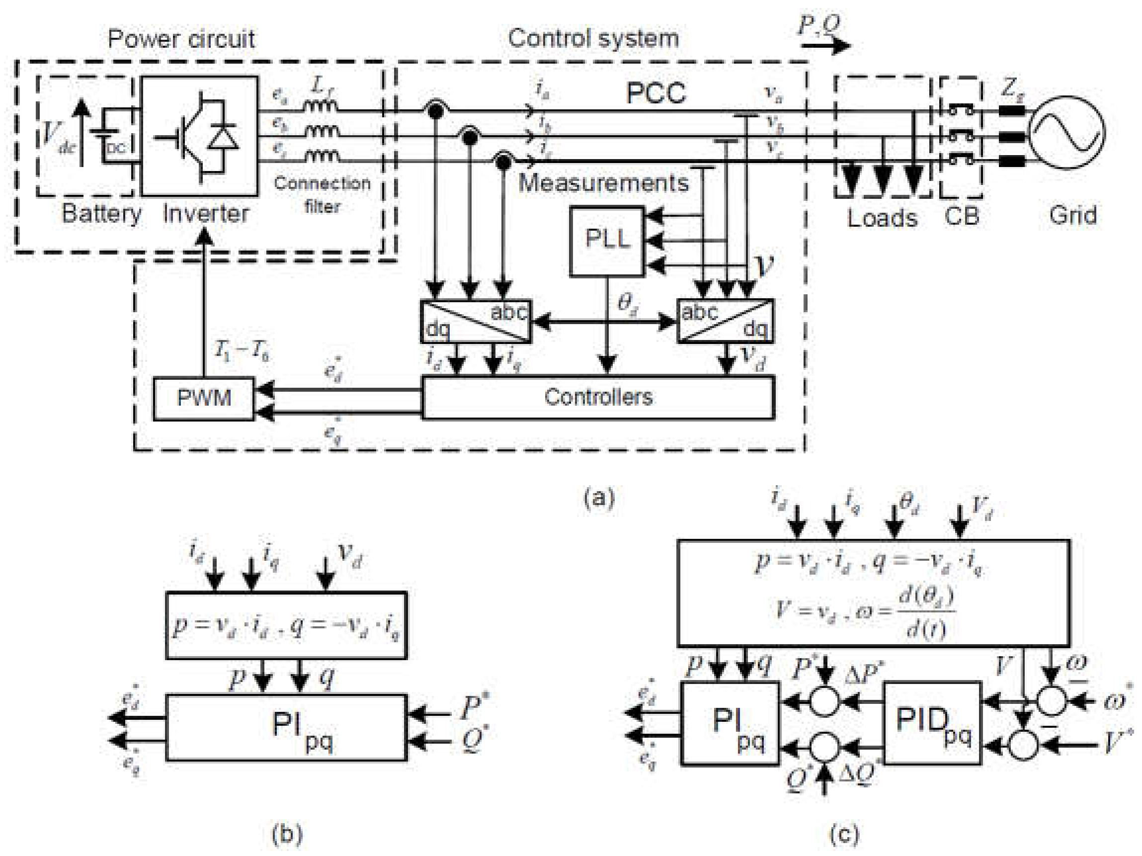
Figure 1a presents the battery energy storage system consisting of a power circuit and a control system.

2.1. Power Circuit

The power circuit consists of the battery, three-phase three-leg inverter, and the connection filter. The battery can be simply modeled as a constant dc voltage source, as shown in Figure 1a, taking into account that the time duration of the black start or islanding operation is relatively short, e.g., several seconds. Note that in our project, we used a 264 KVA battery with an internal resistance of 0.01 Ohm. Using these specifications, the internal resistance of the battery had a small impact on our simulation results (e.g., 0.9% impact on the maximum frequency deviation). Therefore, we did not include the internal resistance of the battery in Figure 1. The three-phase three-leg ac/dc inverter provides a bidirectional power exchange in-between the battery and the ac grid. The connection filter is an electrical inductor that is placed between the inverter and the point of common coupling. Note that to enable the demand response (DR) in Figure 1a, a fast-controlled thermostatic load is connected to the point of common coupling.

2.2. Control System

In Figure 1a, the measurement block is responsible for measuring the three-phase BESS’s voltage and current at the point of common coupling (PCC). In a two-axis synchronous reference frame ( d q ), the calculation block is responsible for providing the d   and q -axis currents (i.e., i d and i q , respectively) and voltages (i.e., v d and v q , respectively) using the phase angle obtained from the phase-locked loop (PLL). The d q current and voltages are the inputs to the controllers. Depending on the operating mode (i.e., grid-connected, islanding, or black start), the controllers will have different configurations that will be detailed below. The output of the controllers is the inverter’ voltages (i.e., e d and e q ), which are sent to the pulse width modulation (PWM) block. The six control signals T 1 T 6 are then provided to six power inverter switches.

3. Control System Strategies

The BESS system has three operation modes (i.e., connected mode, islanding, and black start mode) and two control strategies (i.e., grid feeding control and grid supporting control strategies). While the grid feeding is employed during the grid-connected mode (mode I), the grid supporting control strategy is used during the islanding (mode II) and black start (mode III) operating modes. The control system will switch between these two control strategies according to the related operating mode.

3.1. Grid Feeding Controller

Figure 1b shows the grid feeding controller. The controller only follows the prespecified set points for the active power P * and reactive power Q * using the PI controller. In other words, during this mode, the BESS unit does not provide any frequency or voltage support.

3.2. Grid Supporting Controller

Figure 1c presents the grid-supporting controller. The BESS unit controls the active and reactive power at the PCC, taking into account the voltage and frequency, respectively. In other words, the frequency of the islanded network is measured to adjust the active power, whereas, in a decoupled manner, the reactive power is mainly controlled according to the voltage. Three separate controllers for modes II and III are employed as follows:
  • Inertia emulation controller: Since in modes II and III, the total inertia of the islanded area has a very low value, an inertial emulation controller using the frequency derivative (i.e., rate-of-change-of-frequency ROCOF) is proposed and implemented to increase the effective system inertia.
  • Frequency and voltage droop controllers: The conventional frequency and voltage droop controllers are implemented using proportional controller values P p and P q , respectively. In general, droop controllers are automatically and locally activated to arrest the initial frequency drop right after a contingency event or during the seamless islanding mode within a few seconds in a decentralized manner.
  • Secondary controller: The frequency and voltage secondary controllers are implemented using integral controller values I p and I q , respectively. This control is typically implemented to automatically recover the system frequency to the rated value within a few minutes in a centralized way following a contingency event or during the seamless islanding transition.

3.3. Mode Switching Controller

As shown in Figure 2, during grid-connected mode (i.e., mode I), the grid-feeding power converter only provides the prespecified active and reactive power set points. In other words, during this mode, the BESS unit does not provide any frequency or voltage support. If, due to the scheduled maintenance or faults, the main grid is disconnected from the islanded area, then the BESS control system immediately sets the values of PID controller I. At the same time, to implement the fast-controller load scheme, the BESS control evaluates and compares the actual fast controller load consumption with the pre-disturbance grid active power values. The main objective of the controller is to minimize the islanded area active power mismatch, taking into account both the pre-disturbance grid active power and fast-controlled loads consumption. Accordingly, the control system decides whether to disconnect or, if available, connect to additional fast controlled loads. Finally, if the transition from grid-connected to islanding operating mode is successful, or in other words, the frequency and voltage remain with allowable limits during the seamless transition, then the islanded area is operated until the main grid becomes available again. Otherwise, if the transition is unsuccessful, then to minimize the interruption time of the power supply, it is proposed to perform the black start after a pre-defined time interval. To this end, it is also proposed to use PID controller II until the black start is successfully completed. Then the PID controller II values could be reset, and during islanding operating mode, PID controller I values are used again. In the end, when the upstream grid becomes available again, then the islanded area is synchronized to the main grid using synchrotact.

4. Case Studies and Simulation Scenarios

The proposed BESS controller is simulated in a three-phase 400 V LV distribution network downstream of a secondary MV/LV substation. As shown in Figure 3, the distribution network consists of a battery energy storage system (BESS), three photovoltaic (PV) solar cells, an MV grid connection, a fast controlled thermostatic load, and three residential loads. Note that each of these three loads corresponds to several individual points of supply, which were aggregated for the sake of simplicity.
The base power, rated AC voltage, and frequency are 250 KVA, 400 V, and 50 Hz, respectively. The power capacity of the electrical components, shown in Figure 3, is provided in Table 1.

4.1. Photovoltaic Solar Cell Model

A photovoltaic unit is typically composed of the following parts:
  • Roof-top solar cell modules
  • DC/DC boost converters
  • AC/DC converter
In short, the roof-top solar cell modules directly convert the sunlight into electricity by using semiconductors. Moreover, DC/DC boost converters, which connect the solar cell modules to the AC/DC converters, not only help reduce the PV unit current by increasing the output DC voltage but also efficiently adjust the operating point of the solar cell modules using maximum power point tracking (MPPT) algorithms. To simplify the model of solar cell modules and DC/DC boost converters, they are modeled as constant DC voltage sources in the simulations.
In order to model an AC/DC converter of the PV unit, it is assumed that it is equipped with six insulated-gate bipolar transistor (IGBT) switches, which are controlled and actuated by the PV unit control system. As shown in Figure 1b, as a grid-feeding power converter, the PV unit inverter mainly controls the active and reactive power close to their reference values; therefore, the PV unit power mostly remains constant during the seamless transition from grid-connected to islanded mode.

4.2. Dynamic Loads

In general, the composite loads are typically divided into two broad categories of the static and dynamic loads (e.g., heating systems and induction motors). Note that in the simulations, both dynamic and static loads are taken into consideration and modeled as follows: Static loads can be modeled as a constant current (CC), constant power (CP), or constant impedance (CI). Since the residential and industrial networks include a large number of resistive loads, thus the simple constant impedance load is only used for representing static loads. In addition, the fast controlled thermostatic load, which is mainly used for dissipating the over production of PV electricity during islanded operation, is modeled by a resistance. Dynamic loads are considered as three-phase squirrel cage induction machines.

4.3. Grid-Connection Model

The upstream MV grid connection is modeled as a three-phase four-wire balance system that has three voltage sources in the star. These sources will be connected to the low-voltage distribution network via an impedance ( R + j X ). The three-phase short circuit of the grid is 40 MVA, and the X/R ratio is set at 7.

4.4. Simulation Scenarios

Two sets of simulation scenarios are given for I) seamless transition to islanding and II) black start after a supply interruption.

4.4.1. Simulation Scenarios for Seamless Transition to Islanding

The evolution of the system frequency during the transition from grid-connected to islanded mode using the BESS unit is represented schematically in chronological order in Figure 4. Initially, the upstream grid provides the frequency and voltage support. Then, at Point 1, the grid will become disconnected from the islanded area, and, as a result, the frequency will start to deviate from the nominal value. At Point 2, the fast load control dummy load will connect or disconnect to help suppress the deviation of the frequency. On the one hand, if the frequency reaches the minimum or maximum value, then the BESS unit is shut down, and, as a result, the islanding is not successful. Note that the same holds true for the voltage deviations. On the other hand, if the BESS unit could control the frequency and voltage within allowable limits, then the islanding would successful. Note that in these simulations, for the seamless transition to islanding, the reactive power of PV units 1, 2, and 3 is equal to zero.
The simulation scenarios for seamless transition to islanded operation are presented in more detail below. The base case simulation scenario is created and simulated according to the grid information provided in Section 4.1, Section 4.2 and Section 4.3. Sensitivity analyses for islanded operating mode A are performed as follows:
  • Scenario A1: Different grid disturbance power values
  • Scenario A2: Different shares of dynamic and static loads with respect to the residential, industrial, and commercial areas
  • Scenario A3: Different secondary PI controller values
  • Scenario A4: Fast controlled thermostatic load scheme

4.4.2. Simulation Scenarios B1 and B2 for the “black Start” Mode

In order to evaluate the “black start” capability of the BESS unit, two simulation scenarios (i.e., B1 and B2) are defined and addressed in this section. Note that the BESS unit controller parameters during the “black start” mode are different compared to the islanding operating mode. In fact, in order to help further suppress the large frequency and voltage deviations during the black start mode, not only the primary and secondary controllers’ values are accordingly modified and adjusted, but also a higher value for derivative (D) controllers is added into the active power and frequency and reactive power and voltage controllers. Note that the values for the PID controllers are adjusted after performing a very extensive iteration of trial and error. In general, since the voltage and frequency variations during the black start are larger than the case in the islanding operation, the PID values for the black start mode are lower.
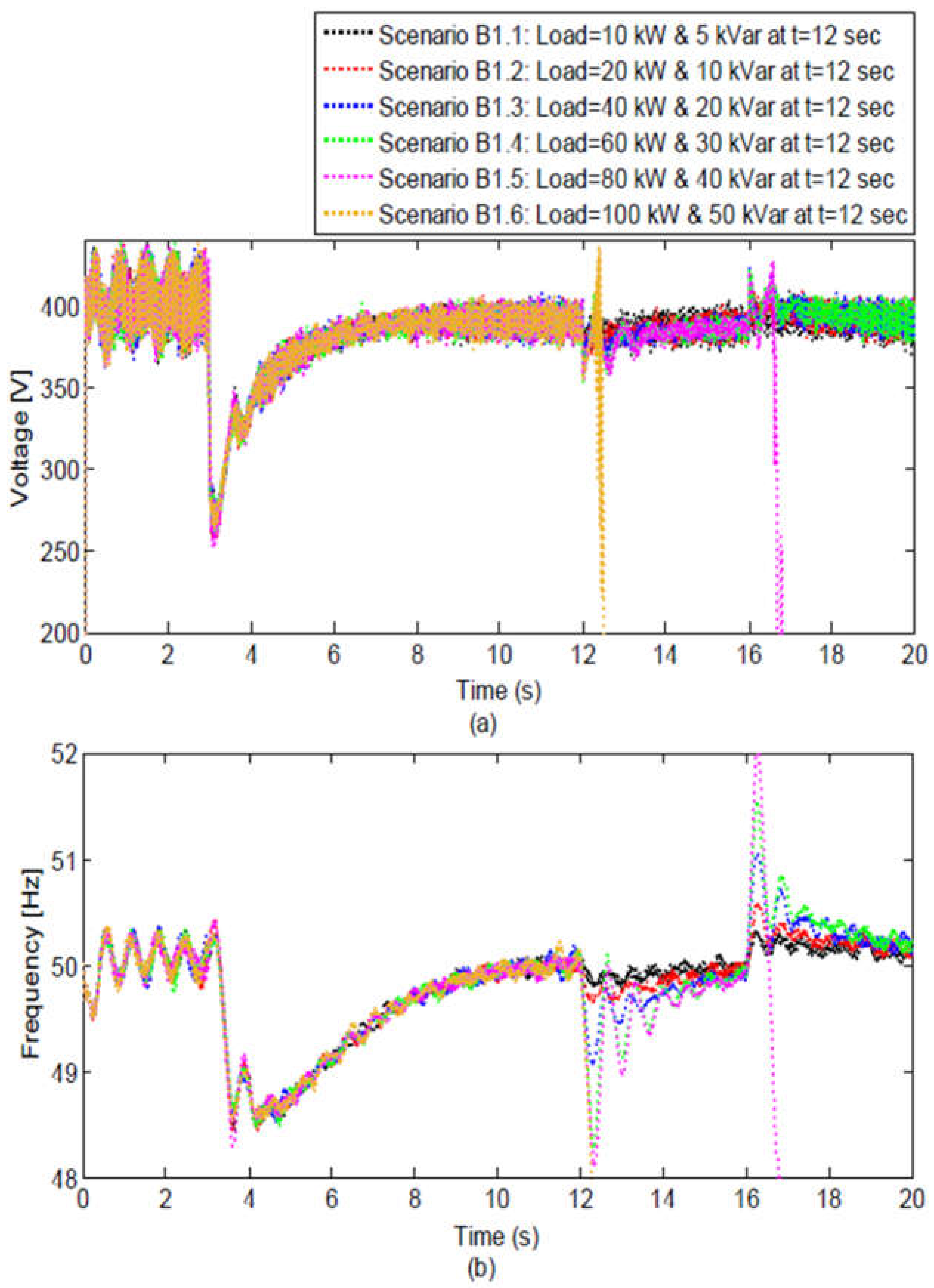
  • Case study B1 for “black start” mode: In order to evaluate the BESS performance for picking up different units during the “black start” mode, case study B1 is defined and presented in Figure 5a. At the start point, how much constant impedance load 1 can be picked up by the BESS unit will be evaluated. Then at Point 1, an induction machine is connected to the grid, and later on, at Point 2, constant impedance load 2 is connected. Finally, at Point 3, a PV unit, which is modeled as a negative load equal to the constant impedance load 2, is connected to the grid. Thus, with this chronological order, we can evaluate the BESS unit performance during the “black start” mode for different types of units. In the simulation scenarios, the constant impedance load is picked up at t = 12 s, and then the PV unit is connected at t = 16 s.
  • Case study B2 for “black start” mode: In order to evaluate the BESS performance when a large number of loads and PV units are picked up, case study B2 is defined and presented in Figure 5b. At the start point, constant impedance load 1 is picked up by the BESS unit. Then, at Point 1, an induction machine is connected to the grid, and later on at Points 2, 3, and 4, constant impedance loads 2, 3, and 4 are connected, respectively. Finally, at Points 5, 6, and 7, PV units, which are modeled as negative loads equal to constant impedance loads 2, 3, and 4 are connected to the grid. Thus, with this chronological order, we can evaluate the BESS unit performance during the “black start” mode, when a large number of units are connected to the grid. Note that for the black start mode, the size of the PV units was considered the same as the size of the constant impedance loads where the PV units have a value for their reactive power. Though in practice, the PV units have a relatively low value of reactive power. The simulation results for the black start mode remain intact and valid in the case that the reactive power of the PV units is set to zero as well.

5. Simulation Results and Discussion

This section mainly addresses and presents the simulation results of islanding, including scenarios A1 to A4. Later on, the simulation results of the “black start” mode for scenarios B1 and B2 are presented and discussed. Note that all simulations have been implemented and carried out using Matlab/Simulink.

5.1. Simulation Results of Islanding Operation Scenarios

To introduce the chronological order of simulations, as generally shown in Figure 4, the grid starts providing reactive and active power to the distribution area at t = 0 s, and after 200 ms, both the voltage and frequency are stabilized and controlled close to their corresponding rated values by the upstream MV grid. Later on, the MV grid is disconnected from the islanded area, and immediately the BESS secondary frequency and voltage control is activated. The BESS capability to control the voltage and frequency within allowable limits is shown and discussed below for scenarios A1 to A4. In the following simulations for the islanding scenarios, the allowed frequency range is considered to be between 48 and 52 Hz (8% of the nominal value), while the allowed voltage range is considered to be between 300 and 500 V (50% of the nominal value is used taking into account various standards related to the voltage dips and voltage swells (e.g., EN 50160 and EN 61000) as well as the time duration of the voltage dip (e.g., 100–1000 ms) during the islanding).

5.1.1. Simulation Results of Scenario A1 for Different Grid Power Values

Figure 6 shows that after t = 0 s, the voltage and frequency are stabilized close to their rated values, and at t = 0.5 s, the grid is disconnected from the islanded area. For scenario base case A, the BESS unit is successfully able to control the voltage and frequency within the limits. As shown in Figure 6a,b, the maximum frequency and voltage deviation for the base case A scenario are 50.66 Hz and 335 V, respectively. On the one hand, for scenario A.1.1, the BESS unit is initially able to control the voltage and frequency within allowable limits; however, it reaches its maximum power limit at t = 1.5 s and later on, the system is shut down. From scenarios A.1.1 to A.1.2, the amount of grid power disturbance increases from 100 (i.e., 0.4 pu) to 200 kW (i.e., 0.8 pu), and consequently, both voltage and frequency highly deviate during the islanding, which shuts down the island. On the other hand, for scenario A.1.3, the BESS unit is able to control the frequency and voltage within allowable limits. As shown in Figure 6a,b, the maximum frequency and voltage deviation for scenario A.1.3 are 51.35 Hz and 300 V, respectively. Contrary to scenario A.1.3, the BESS unit does not reach its limits, and consequently, the islanding is successful after several seconds. From scenarios A.1.3 to A.1.4, the amount of grid power disturbance increases from −100 (i.e., −0.4 pu) to −200 kW (i.e., −0.8 pu), and, consequently, both voltage and frequency highly deviate during the islanding, which shuts down the island.

5.1.2. Simulation Results of Scenario A2 for Different Shares of Dynamic and Static Loads

In scenario base case A, it is assumed that the dynamic (i.e., induction machines) and static (i.e., constant impedance) loads have 30% and 70% of the total load consumption, respectively. Figure 7 shows that after t = 0 s, the voltage and frequency are stabilized close to their rated values, and at t = 0.5 s, the grid is disconnected from the islanded area. For scenario base case A, the BESS unit is successfully able to control the voltage and frequency within the limits. As shown in Figure 7a,b, the maximum frequency and voltage deviation for the base case A scenario are 50.66 Hz and 335 V, respectively. From the base case scenario A to scenario A.2.1, where the share of induction machines decreases from 30% to 15%, the maximum frequency and voltage deviations considerably vary from 50.66 to 50.80 Hz and from 335 to 325 V, respectively. In addition, from the base case scenario A to scenario A.2.2, where the share of induction machines will increase from 30% to 60%, the maximum frequency and voltage deviations highly improve from 50.66 to 50.40 Hz, and from 335 to 345 V, respectively.

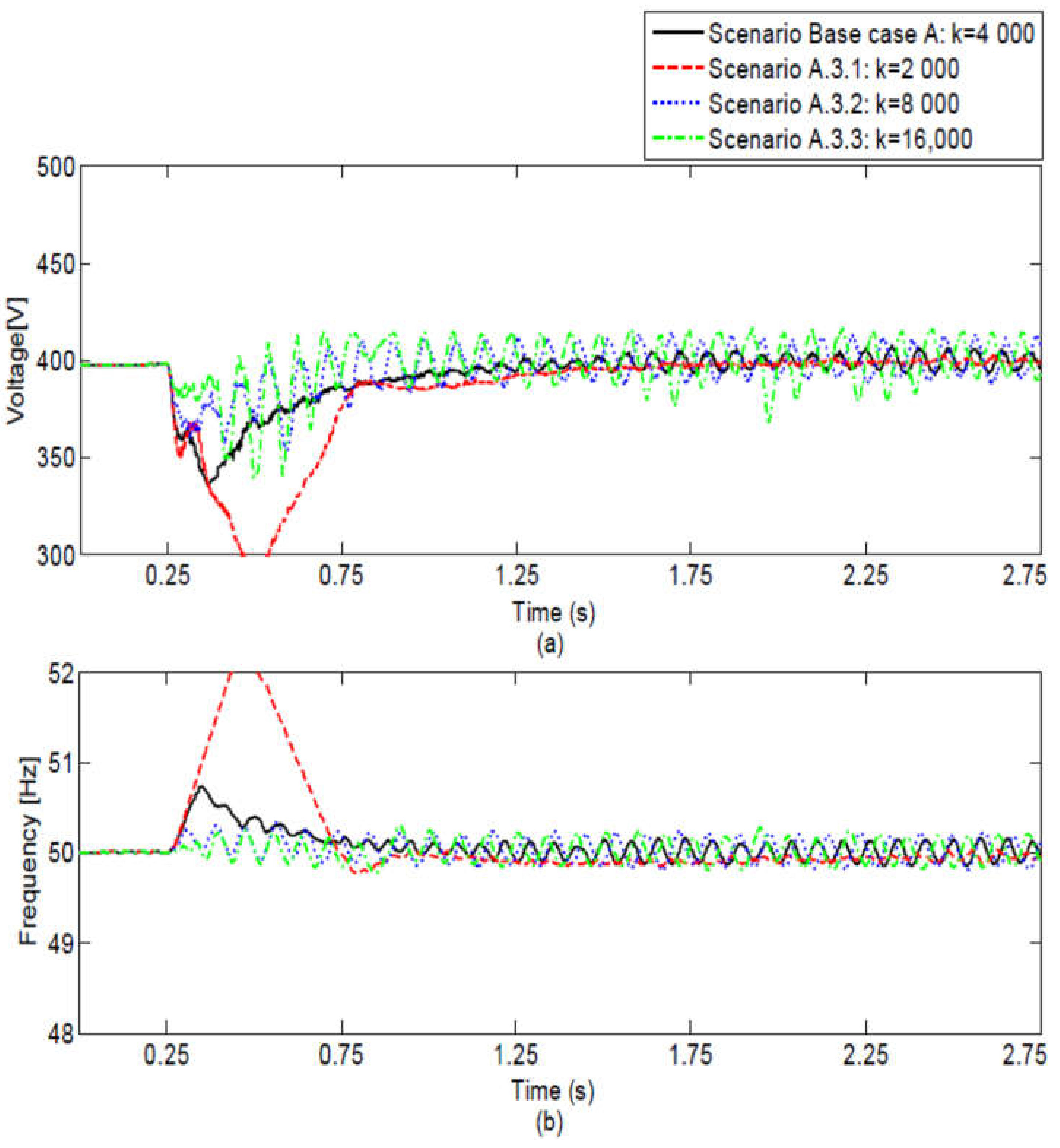
5.1.3. Simulation Results of Scenario A3 for Different Secondary Controller Gain Values

In scenario base case A, it is assumed that both secondary controllers (i.e., voltage-reactive power and frequency-active power controllers) have the general gain of 4000, according to Table 2. Figure 8 shows that after t = 0 s, the voltage and frequency are stabilized close to their rated values, and at t = 0.5 s, the grid is disconnected from the islanded area. For scenario base case A, the BESS unit is successfully able to control the voltage and frequency within the limit values using the secondary controllers. As shown in Figure 8a,b, the maximum frequency and voltage deviation for the base case A scenario are 50.66 Hz and 335 V, respectively. From the base case scenario A to scenario A.3.1, where the secondary controllers gain reduces from 4000 to 2000, the maximum frequency and voltage deviations considerably vary from 50.66 to 52.21 Hz, and from 335 to 288 V, respectively. Thus, in scenario A.3.1, the islanded area is shut down because both frequency and voltage reach their allowable limits. In addition, from base case scenario A to scenario A.3.2, where the secondary controller gains increase from 4000 to 8000, the maximum frequency and voltage deviations highly improve from 50.66 to 50.31 Hz, and from 335 to 355 V, respectively. However, from scenario A.3.2 to scenario A.3.3, where the secondary controller gains increase from 8000 to 16,000, the maximum frequency and voltage deviations negligibly improve. As can be seen in Figure 8a,b, high values of secondary controller gains result in high-amplitude high-frequency oscillations of both frequency and voltage due to having a lower stability margin. Therefore, although the frequency and voltage deviations in scenarios A.3.2 and A.3.3 might considerably be better compared to base case scenario A, the steady-state high-amplitude high-frequency oscillations are not acceptable for the island operation. Additionally, this might tend the islanded system to instability.

5.1.4. Simulation Results of Scenario A4 for Demand Response (Fast Controlled Dummy Load)

In order to evaluate the performance of the BESS unit with and without demand response, the fast-controlled dummy load is used. In scenario A.4.1, where the grid power for islanding operation is equal to 100 kW (or 0.4 pu), the demand response is not active, and, consequently, the dummy load remains connected at t = 2 s. However, in scenario A.4.2, where the grid power for islanding operation remains equal to 100 kW (or 0.4 pu), the demand response is active and, consequently, the dummy load is disconnected at t = 2 s. Figure 9a,b shows that both voltage and frequency reach their maximum limits with demand response. In fact, the BESS unit is not able to quickly compensate the grid power disturbance of 100 kW (i.e., 0.4 pu). However, in scenario A.4.2, by enabling the demand response, the dummy load is quickly disconnected from the grid within milliseconds, which helps the BESS unit stabilize the system frequency and voltage. As shown in Figure 9a,b, the maximum frequency and voltage deviation for scenario A.4.2 are 49.6 Hz and 420 V, respectively.

5.2. Simulation Results of “Black Start” Mode Scenarios

The simulation results of the “black start” mode scenarios (i.e., B1 and B2) are presented in this section. The chronological order of simulations for each scenario is explained and highlighted as follows:

5.2.1. Simulation Results of Scenario B1 for Picking up Different Types of Units

Within scenario B1 framework, firstly, the BESS capability to pick up different types of units, such as static loads (i.e., constant impedance loads), dynamic loads (i.e., induction machines), and PV units, is carefully evaluated and studied. While the frequency and voltage are presented in Figure 10, the active and reactive power of the BESS unit is shown in Figure 11. As shown in Figure 11, for all scenarios at t = 0 s, the constant impedance load of 60 kW and 15 kVAr is successfully picked up. Later at t = 3 s, the induction machine of 40 kW and 30 kVAr is successfully connected to the islanded system; however, both voltage and frequency significantly drop to 260 V and 48.3 Hz, respectively. Note that in scenarios B1.2 and B2, we assumed that all induction machines are directly connected to the distribution network (in other words, we assumed that all induction machines are totally coupled and connected to the grid with no power-electronic interface in-between the induction machine and the islanded area), and as a consequence, they could consume very high inrush currents (e.g., up to seven times the rated current). This obviously leads to a significant drop in both voltage and frequency during the “black start” mode. However, it is highly worth mentioning that in present-day distribution networks, most of the currently installed induction machines inside the distribution networks are connected to the grid through a power electronic interface. As a consequence, they do not consume very high inrush currents following their connection to the islanded area, and consequently for the “black start” analysis, these power electronically interfaced induction machines can be fairly modeled as constant power loads (and not as the dynamic loads). In conclusion, in practice, both the voltage and frequency response of the BESS unit following the connection of power electronically-interfaced induction machines, should be remarkably better compared to the here-presented simulation results, in which induction machines are directly connected to the islanded area. At t = 12 s, different values of constant impedance load 2 are connected to the BESS unit, and the frequency and voltage variations are evaluated. Generally, as expected, the frequency and voltage variations increase by the size of the load, as shown in Figure 10. The BESS unit is able to successfully control the frequency and voltage within the limits for scenarios B1 2.1 to 2.5, where the constant impedance load 2 size increase from 10 kW and 5 kVAR to 80 kW and 40 kVAR. However, in scenario B1 2.6, the BESS unit is not able to pick up the load of 100 kW and 50 kVAR. At t = 16 s, different values of PV unit 1, which are considered as negative constant impedance 2 values, are connected to the BESS unit, and the frequency and voltage variations are evaluated. Generally, as expected, the frequency and voltage variations increase by the size of the PV unit, as shown in Figure 10. The BESS unit is able to successfully control the frequency and voltage within the limits for scenarios B1 2.1 to 2.4, where the PV unit size increases from 10 kW and 5 kVAR to 60 kW and 30 kVAR. However, in scenario B1 2.5, the BESS unit is not able to pick up the PV unit of 80 kW and 40 kVAR.

5.2.2. Simulation Results of Scenario B2 for Picking up a Large Number of Units

Within scenario B2′s framework, firstly, the BESS capability to pick up a large number of units, such as static loads (i.e., constant impedance loads), dynamic loads (i.e., induction machines), and PV units, is carefully evaluated and studied. While the frequency and voltage are presented in Figure 12, the active and reactive power of the BESS unit is shown in Figure 13. As shown in Figure 13, for all scenarios at t = 0 s, the constant impedance load of 40 kW and 35 kVAR is successfully picked up. Later, at t = 0.5 s, the induction machine of 40 kW and 30 kVAR is successfully connected to the islanded system; however, both voltage and frequency significantly drop to 260 V and 48.3 Hz, respectively. At t = 6 s, t = 12 s, t = 16 s, and t = 21 s, four identical constant impedance loads of 20 kW are connected, in order, to the islanded area. As can be seen in Figure 13, the BESS unit can successfully keep both voltage and frequency within the limits of 380 V and 48.4 Hz, respectively. At t = 26 s, t = 30 s, t = 35 s, and t = 40 s, four identical PV units, which are considered as negative constant impedance loads, are connected to the BESS unit. As can be seen in Figure 13, the BESS unit can successfully keep both voltage and frequency within the limits of 430 V and 51.1 Hz, respectively. Finally, it is worth mentioning that although the BESS performance is fairly acceptable for the sudden connection of PV units, during experimental tests in practice, PV units are only permitted to be slowly connected to the islanded area under monitored and controlled conditions. Therefore, it could be fairly claimed that our simulations take into account the worst operating conditions for the “black start” mode.

5.3. Discussion

The results have shown that, during the islanding operation, the BESS performance largely depends on the following parameters:
  • Grid power disturbance: It was observed in the simulations that the BESS unit had the large capability to control the island for the high values of grid power disturbance, e.g., 0.4 pu. Despite this, for the very high values of grid power disturbance, e.g., 0.8 pu, the battery storage unit was not able to adequately control the island. Moreover, the power variation of the BESS unit did not necessarily have the same value for the upward or downward reserves.
  • Share of dynamic loads, such as induction machines: The dynamic loads, such as induction machines, were able to largely increase the island’s inertial response. As a result, the performance of the BESS unit was notably improved when the share of the induction machines increased in the islanded area. By the way, it was noted that the newly installed induction machines, which are typically connected to the grid using the power electronic converters, are able to considerably deteriorate the inertial contribution of the induction machines to the grid.
  • Secondary controller gain: The gain of the secondary controller undoubtedly had a large impact on the BESS unit’s performance. While the very low values of the controller gains could result in poor performance of the battery storage unit, the use of very large values for the controller gains could also lead to the steady-state high-magnitude high-frequency voltage and frequency oscillations in the islanded area. As the use of both large and low values could make the islanded area unstable, for the islanding operation, the gains of the secondary controller shall be tuned and carefully adjusted.
  • Initial set points of the BESS unit before islanding: If before the islanding, the set points of the battery storage unit were close to the maximum or minimum limits for the power, the performance of the BESS unit could be largely decreased, and as a result, the area could be shut down. Therefore, it is strongly suggested that the initial set points of the battery storage unit would be carefully adjusted such that the battery storage system has enough upward or downward reserves of power during the islanding operation
  • BESS unit power: Taking into account the previous point, i.e., point A. 4, if the size of the battery storage unit (in kW) also had a very low value, then the battery storage unit had limited capabilities to control the frequency and voltage within the allowable limits. Hence, we also recommend that the size of the battery storage unit is carefully selected and defined, taking into account the power disturbance of the grid, total consumption of the loads, and the power production of the PV units in the islanded area.
  • Demand response, such as fast load control, in the area: Fast controlled dummy load had a significant potential to help the battery storage unit successfully stabilize the area, whereas the area shut down without the fast dummy load control.
During the “black start” mode, the performance of the battery storage unit largely depends on the following parameters:
  • Type of loads connected: According to the simulations, the dynamic loads, such as induction machines, could have a very large inrush current that significantly reduced both frequency and voltage during the “black start” mode. However, if the size of the load consumption remains the same, the battery storage system had better performance for constant impedance loads in comparison to the induction machine loads. Finally, it was indicated that the newly installed induction machines are typically connected to the grid via the power electronic converters. This helps the high-amplitude inrush currents be avoided after their connection to the islanded area. In these cases, the induction machines using the power electronic converters can be modeled as constant power loads (and not as dynamic loads).
  • Size of the loads connected to the area: It is obvious that the feasibility of a successful “black start” mode is mainly dependent on the connected load size in the islanded area. In general, the BESS unit had a large capability to pick up large loads, such as 0.32 pu.
  • PV unit’s size: Despite the fact that, in practice, the PV units are gradually connected to the area under controlled and monitored conditions with a very slow rate, the performance of the battery storage system was very acceptable even for the case that the PV units with 0.08 pu are suddenly connected to the area.
  • Type of secondary controller: Next to the conventional PI controllers used for the secondary controller, the derivative (D) controllers were added to the secondary controllers to notably improve the capability of the BESS unit for the “black start” mode. In fact, as the total response of the inertia in the area is relatively low during the black start mode, the derivative controllers are able to effectively emulate and improve the inertial response of the islanded area and, consequently, help suppress the high-voltage and frequency deviations during the load pick up process.
Lastly, the simulations provided some further lessons learned where extensive sensitivity analyses were also made on other relevant aspects of the grid. Note that due to limited space and relevance, those simulation results were not provided in this paper. It was noted that the unbalanced load flows, as well as the state of charge of the battery, had a negligible impact on the islanding mode. However, if the BESS unit does not properly control the large, unbalanced load flows during the islanding mode, then the PV unit or single-phase load connected to the area could be damaged because of the large single-phase current. Moreover, it has the potential to activate the fuse or over-current relay protection of the specific PV unit or load. Therefore, during large, unbalanced load flows, not only the BESS unit performance should be evaluated by the three-phase voltages amplitudes and frequency, but also during islanding mode, the variation of current of each single-phase should be additionally controlled and monitored.

6. Conclusions

In this paper, the islanding performance of a BESS unit was evaluated and studied via simulations employing Matlab Simulink for both “islanding operation” and “black start” islanding modes.
In order to do this, a novel three-mode PID controller comprising (1) inertia emulation, (2) frequency-active power and voltage-reactive power droops, and (3) secondary frequency and voltage controllers were developed.
Extensive sensitivity analyses were carried out so as to assess the proposed controller performance under various grid operating conditions. The parameters evaluated included: pre-disturbance grid power, BESS capacity, battery state of charge, unbalanced three-phase load flows, implemented power-frequency controller parameters, or various shares of dynamic and static loads.
Generally, the simulations showed that the BESS unit practically and technically had a high capability to maintain and operate the area by quickly controlling the frequency and voltage. During the seamless transition from grid-connected to islanded operation, the BESS showed a large potential to adequately control both voltage and frequency, despite the fact that the amount of active and reactive power mismatch during the transition was relatively high. The implementation of the fast-controlled loads for demand response purposes further improved the transition during the islanding operation. If the islanding did fail, the BESS is able to restore the microgrid step-by-step, picking up the grid’s loads and DERs while maintaining the voltage and frequency within the acceptable limits. The mode switching controller performed smoothly during the transition of various modes, namely grid-connected, islanded, and black start modes. The alternative methods to the design of the controller and its parameters could be explored in future research.

Author Contributions

Conceptualization, S.I., R.C., P.F., P.G.-G. and A.R.-C.; methodology, S.I., R.C., P.F., P.G.-G. and A.R.-C.; software, S.I; validation, S.I., R.C. and A.R.-C.; formal analysis, S.I., R.C., P.F., P.G.-G. and A.R.-C.; investigation, S.I.; resources, S.I., R.C., P.F., P.G.-G. and A.R.-C.; data curation, S.I., R.C. and A.R.-C.; writing—original draft preparation, S.I., R.C. and A.R.-C.; writing—review and editing, S.I., R.C., P.F., P.G.-G. and A.R.-C.; supervision, R.C., P.F. and P.G.-G.; project administration, R.C., P.F. and P.G.-G.; funding acquisition, R.C., P.F. and P.G.-G. All authors have read and agreed to the published version of the manuscript.

Funding

During the PhD period (2012–2017), the work of S. Izadkhast were funded by the European Commission’s Joint Doctorate on Sustainable Energy Technologies and Strategies (SETS). In particular, this work was developed in the context of the GRID4EU Project supported by the European Commission under grant agreement no. 268206. The sole responsibility for the content of this paper lies with the authors. It does not represent the opinion of the European Commission (EC). The EC is not responsible for any use that may be made of the information contained therein.

Institutional Review Board Statement

Not applicable.

Informed Consent Statement

Not applicable.

Data Availability Statement

Data is contained within this article.

Conflicts of Interest

The authors declare no conflict of interest.

References

  1. Zhao, B.; Dong, X.; Bornemann, J. Service Restoration for a Renewable-Powered Microgrid in Unscheduled Island Mode. IEEE Trans. Smart Grid 2015, 6, 1128–1136. [Google Scholar] [CrossRef]
  2. Penaloza, J.D.R.; Adu, J.A.; Borghetti, A.; Napolitano, F.; Tossani, F.; Nucci, C.A. A Power Control Scheme for the Islanding Transition of a Microgrid with Battery Energy Storage Systems. In Proceedings of the 2019 IEEE International Conference on Environment and Electrical Engineering and 2019 IEEE Industrial and Commercial Power Systems Europe (EEEIC/I CPS Europe), Genova, Italy, 11–14 June 2019; pp. 1–6. [Google Scholar]
  3. Chen, M.; Rincon-Mora, G. Accurate electrical battery model capable of predicting runtime and I–V performance. IEEE Trans. Energy Convers. 2006, 21, 504–511. [Google Scholar] [CrossRef]
  4. Izadkhast, S.; Garcia-Gonzalez, P.; Frias, P. An Aggregate Model of Plug-In Electric Vehicles for Primary Frequency Control. IEEE Trans. Power Syst. 2015, 30, 1475–1482. [Google Scholar] [CrossRef]
  5. Lee, S.-J.; Kim, J.-H.; Kim, C.-H.; Kim, S.-K.; Kim, E.-S.; Kim, D.-U.; Mehmood, K.; Khan, S. Coordinated Control Algorithm for Distributed Battery Energy Storage Systems for Mitigating Voltage and Frequency Deviations. IEEE Trans. Smart Grid 2015, 7, 1713–1722. [Google Scholar] [CrossRef]
  6. Mercier, P.; Cherkaoui, R.; Oudalov, A. Optimizing a Battery Energy Storage System for Frequency Control Application in an Isolated Power System. IEEE Trans. Power Syst. 2009, 24, 1469–1477. [Google Scholar] [CrossRef]
  7. Wade, N.S.; Taylor, P.C.; Lang, P.D.; Jones, P.R. Evaluating the benefits of an electrical energy storage system in a future smart grid. Energy Policy 2010, 38, 7180–7188. [Google Scholar] [CrossRef] [Green Version]
  8. Serban, I.; Marinescu, C. Control Strategy of Three-Phase Battery Energy Storage Systems for Frequency Support in Microgrids and with Uninterrupted Supply of Local Loads. IEEE Trans. Power Electron. 2014, 29, 5010–5020. [Google Scholar] [CrossRef]
  9. Serban, I.; Marinescu, C. An enhanced three-phase battery energy storage system for frequency control in microgrids. In Proceedings of the 2012 13th International Conference on Optimization of Electrical and Electronic Equipment (OPTIM), Brasov, Romania, 24–26 May 2012; pp. 912–918. [Google Scholar]
  10. Pilehvar, M.S.; Mirafzal, B. A Frequency Control Method for Islanded Microgrids Using Energy Storage Systems. In Proceedings of the 2020 IEEE Applied Power Electronics Conference and Exposition (APEC), New Orleans, LA, USA, 15–19 March 2020; pp. 2327–2332. [Google Scholar] [CrossRef]
  11. Dong, D.; Wang, P.; Qin, W.; Han, X. Investigation of a microgrid with vanadium redox flow battery storages as a black start source for power system restoration. In Proceedings of the 2014 IEEE 9th Conference on Industrial Electronics and Applications (ICIEA), Hangzhou, China, 9–11 June 2014; pp. 140–145. [Google Scholar]
  12. Li, J.; Ma, X.-Y.; Liu, C.-C.; Schneider, K. Distribution System Restoration With Microgrids Using Spanning Tree Search. IEEE Trans. Power Syst. 2014, 29, 3021–3029. [Google Scholar] [CrossRef]
  13. Nguyen, C.; Flueck, A. Agent Based Restoration With Distributed Energy Storage Support in Smart Grids. IEEE Trans. Smart Grid 2012, 3, 1029–1038. [Google Scholar] [CrossRef]
  14. Kwon, J.; Yoon, S.; Choi, S. Indirect current control for seamless transfer of three-phase utility interactive inverters. IEEE Trans. Power Electron. 2012, 27, 773–781. [Google Scholar] [CrossRef]
  15. Ryan, D.J.; Razzaghi, R.; Torresan, H.D.; Karimi, A.; Bahrani, B. Grid-Supporting Battery Energy Storage Systems in Islanded Microgrids: A Data-Driven Control Approach. IEEE Trans. Sustain. Energy 2021, 12, 834–846. [Google Scholar] [CrossRef]
  16. Ashabani, S.; Mohamed, Y. A Flexible Control Strategy for Grid-Connected and Islanded Microgrids with Enhanced Stability Using Nonlinear Microgrid Stabilizer. IEEE Trans. Smart Grid 2012, 3, 1291–1301. [Google Scholar] [CrossRef]
  17. Bevrani, H.; Shokoohi, S. An Intelligent Droop Control for Simultaneous Voltage and Frequency Regulation in Islanded Microgrids. IEEE Trans. Smart Grid 2013, 4, 1505–1513. [Google Scholar] [CrossRef]
  18. Bidram, A.; Davoudi, A. Hierarchical Structure of Microgrids Control System. IEEE Trans. Smart Grid 2012, 3, 1963–1976. [Google Scholar] [CrossRef]
  19. Jiang, Q.; Xue, M.; Geng, G. Energy Management of Microgrid in Grid-Connected and Stand-Alone Modes. IEEE Trans. Power Syst. 2013, 28, 3380–3389. [Google Scholar] [CrossRef]
  20. Katiraei, F.; Iravani, M.; Lehn, P. Micro-grid autonomous operation during and subsequent to islanding process. IEEE Trans. Power Deliv. 2005, 20, 248–257. [Google Scholar] [CrossRef]
  21. Meegahapola, L.; Robinson, D.; Agalgaonkar, A.; Perera, S.; Ciufo, P. Microgrids of Commercial Buildings: Strategies to Manage Mode Transfer from Grid Connected to Islanded Mode. IEEE Trans. Sustain. Energy 2014, 5, 1337–1347. [Google Scholar] [CrossRef]
  22. Neves, A.; Falcão, A.; Louro, M.; Terras, J.M.; Almeida, B.; Veríssimo, M.; Pinto, J.F.; Damásio, J. Two Years of Battery Energy Storage System performance in automatic islanding in the Portuguese MV network. AIM, Jun. 2019. [Online]. Available online: https://www.cired-repository.org/handle/20.500.12455/272 (accessed on 22 February 2022).
  23. Moreira, C.; Resende, F.; Lopes, J.P. Using Low Voltage Micro- Grids for Service Restoration. IEEE Trans. Power Syst. 2007, 22, 395–403. [Google Scholar] [CrossRef] [Green Version]
  24. Olivares, D.; Mehrizi-Sani, A.; Etemadi, A.; Canizares, C.; Iravani, R.; Kazerani, M.; Hajimiragha, A.; Gomis-Bellmunt, O.; Saeedifard, M.; Palma-Behnke, R.; et al. Trends in Microgrid Control. IEEE Trans. Smart Grid 2014, 5, 1905–1919. [Google Scholar] [CrossRef]
  25. Sebastián, R.; Alzola, R.P. Simulation of an isolated Wind Diesel System with battery energy storage. Electr. Power Syst. Res. 2011, 81, 677–686. [Google Scholar] [CrossRef]
  26. Shafiee, Q.; Guerrero, J.; Vasquez, J. Distributed Secondary Control for Islanded Microgrids—A Novel Approach. IEEE Trans. Power Electron. 2014, 29, 1018–1031. [Google Scholar] [CrossRef] [Green Version]
  27. Tephiruk, N.; Kanokbannakorn, W.; Kerdphol, T.; Mitani, Y.; Hongesombut, K. Fuzzy logic control of a battery energy storage system for stability improvement in an islanded microgrid. Sustainability 2018, 10, 1645. [Google Scholar] [CrossRef] [Green Version]
  28. Worku, M.Y.; Hassan, M.A.; Abido, M.A. Real time energy management and control of renewable energy based microgrid in grid connected and island modes. Energies 2019, 12, 276. [Google Scholar] [CrossRef] [Green Version]
Figure 1. Proposed BESS. (a) Power circuit and control system. (b) Grid-feeding control structure during grid-connected mode. (c) Grid-supporting control structure during seamless islanding and black start modes.
Energies 15 01736 g001
Figure 2. Flow-chart diagram illustrating the proposed local mode switching control.
Energies 15 01736 g002
Figure 3. Distribution network configuration, including photovoltaic solar cells, fast controlled thermo-static load, induction loads, grid connection, and battery energy storage system ( * The voltage and frequency are measured at the point of common coupling).
Energies 15 01736 g003
Figure 4. Simulation events of the system frequency for the “islanding operation” mode in chronological order.
Energies 15 01736 g004
Figure 5. Simulation events of the system frequency for “black start” modes in chronological order; (a) scenario B1, (b) scenario B2.
Energies 15 01736 g005
Figure 6. (a) Island voltage for scenario A1; (b) Island frequency for scenario A1.
Energies 15 01736 g006
Figure 7. (a) Island voltage for scenario A2; (b) Island frequency for scenario A2.
Energies 15 01736 g007
Figure 8. (a) Island voltage for scenario A3; (b) Island frequency for scenario A3.
Energies 15 01736 g008
Figure 9. (a) Island voltage for scenario A4; (b) Island frequency for scenario A4.
Energies 15 01736 g009
Figure 10. (a) Voltage for scenario B1; (b) Frequency for scenario B1.
Energies 15 01736 g010
Figure 11. (a) Active power for scenario B1; (b) Reactive power for scenario B1.
Energies 15 01736 g011
Figure 12. (a) Voltage for scenario B2; (b) Frequency for scenario B2.
Energies 15 01736 g012
Figure 13. (a) Active power for scenario B2; (b) Reactive power for scenario B2.
Energies 15 01736 g013
Table 1. Power capacity, active, and reactive power of the components in the microgrid.
Power Capacity in KVA
BESS264
PV unit 1200
PV unit 2140
PV unit 390
Load 1Static 90 KVA + dynamic 40 KVA
Load 2Static 224 KVA + dynamic 40 KVA
Load 3Static 90 KVA + dynamic 40 KVA
Fast controlled load100 (one 50, two 20, and one 10 KVA)
Table 2. Power, current, primary, and secondary PI(D) controllers for the base case studies of islanding operating and black start mode.
Controller ParameterIslanding OperatingBlack Start
Power and current controllers
2 × Power PI controllerP4.54.5
I3030
Primary and secondary controllers
3 × Frequency-active power PIDP108,000 = 27 × 400015,000
I400,000 = 100 × 400011,250
D01050
3 × Voltage-reactive power PIDP2560 = 0.64 × 400028.8
I24,000 = 6 × 4000144
D00.96
Publisher’s Note: MDPI stays neutral with regard to jurisdictional claims in published maps and institutional affiliations.

