
Design Issues of a Rotating to Linear Motion Magnetic Converter for Short-Distance Transport Applications


Department of Industrial Engineering, University of Padova, 35131 Padova, Italy
*
Author to whom correspondence should be addressed.
Energies 2021, 14(24), 8464; https://0-doi-org.brum.beds.ac.uk/10.3390/en14248464
Submission received: 13 November 2021
/
Revised: 10 December 2021
/
Accepted: 13 December 2021
/
Published: 15 December 2021
(This article belongs to the Special Issue New Advances in Permanent Magnet Electrical Machines)
Abstract
:This paper discusses some design issues of a magnetic rotating to linear motion converter (RLMC), suitable for the propulsion system of a short-distance low-capacity vehicle. It basically operates like a magnetic rack, which executes the contactless conversion of the motor torque into a propulsion thrust, deriving from the interaction of on-board permanent magnet (PM) modules and stationary ferromagnetic steel pieces. A design procedure is set up that deals with both the PM module arrangement and the geometric shape of the steel pieces to optimize different performance aspects. A simplified modeling based on 2D transient finite element analyses is carried out to determine the thrust profile and the RLMC losses, which are essential to assess its practical feasibility. Finally, the characteristics as functions of the load angle and speed are determined to enable the prediction of the dynamic power exchange and then of the net energy demand useful to size the on-board source.

1. Introduction
Magnetic gear (MG) technology is particularly attractive as a replacement of the conventional mechanical gears with the purpose to fulfill some binding application requirements. In particular, the elimination of contact transmission can represent a significant improvement to increase reliability and efficiency, reduce noise, and simplify the drivetrain [1]. Several MG configurations are potentially able to fit different transmission arrangements, often difficult to obtain by mechanical devices unless multiple conversion stages are used. In addition to the more common radial flux coaxial MG (CMG) [2], axial and transverse flux as well as linear type MGs are deeply investigated, assessing their performances for different application ratings and sizes [3,4,5,6,7,8]. The more limited volumetric torque density—generally claimed against the use of mechanical gears—is increasing, reaching values above 200 kNm/m3 thanks to the combination of high-grade permanent magnets (PMs), quasi-Halbach magnetization patterns, high permeable iron core materials, and flux focusing configurations [3,9].
Recently, MGs have been investigated for various transport applications, requiring limited gear ratios (about 10:1 or lower). Two possible design approaches can be recognized:
Another potential MG application consists of the conversion of the rotating to linear motion with the aim to couple a rotating high-speed drive to a low-speed translational load. The basic idea is to eliminate the mechanical gear transmission and at the same time to provide a translational force (thrust) directly to the vehicle, avoiding the exertion of high torque to the wheels. A possible arrangement that can be adapted to this purpose consists of a magnetic lead screw design with both PM and reluctance translators [14,15]. The operating principle based on the cycloid MG enables high force density and low frequency magnetic field, which significantly reduces the eddy current losses. The use of ferromagnetic pieces to replace the PMs on the translators and a skewed assembly of the active parts [16] can mitigate some manufacturing issues. However, its application to a transportation system is not convenient because of the inherent tubular design and the complicated assembly required to realize high stroke lengths.
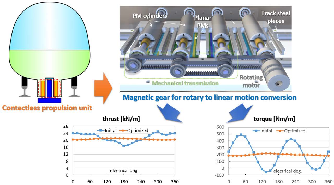
The paper aims to investigate a novel arrangement reproducing a kind of contactless rack-and-pinion device based only on PM magnetic field interaction. Differently from the above configurations, the motion is planar and enables to efficiently convert the high speed/low torque mechanical power of a conventional rotating motor to a low speed/high thrust form, more profitable for the vehicle propulsion. It can be particularly suitable for operation on widely differing route configuration with steep slopes in downtown or in hilly areas, currently served by more invasive and costly maintenance ropeways, aerial tramways, or cable cars [17,18]. The electromagnetic transmission can aid the development of environmentally friendly transport infrastructures, at the same time enabling efficient and safe operation.
2. Proposed Configuration
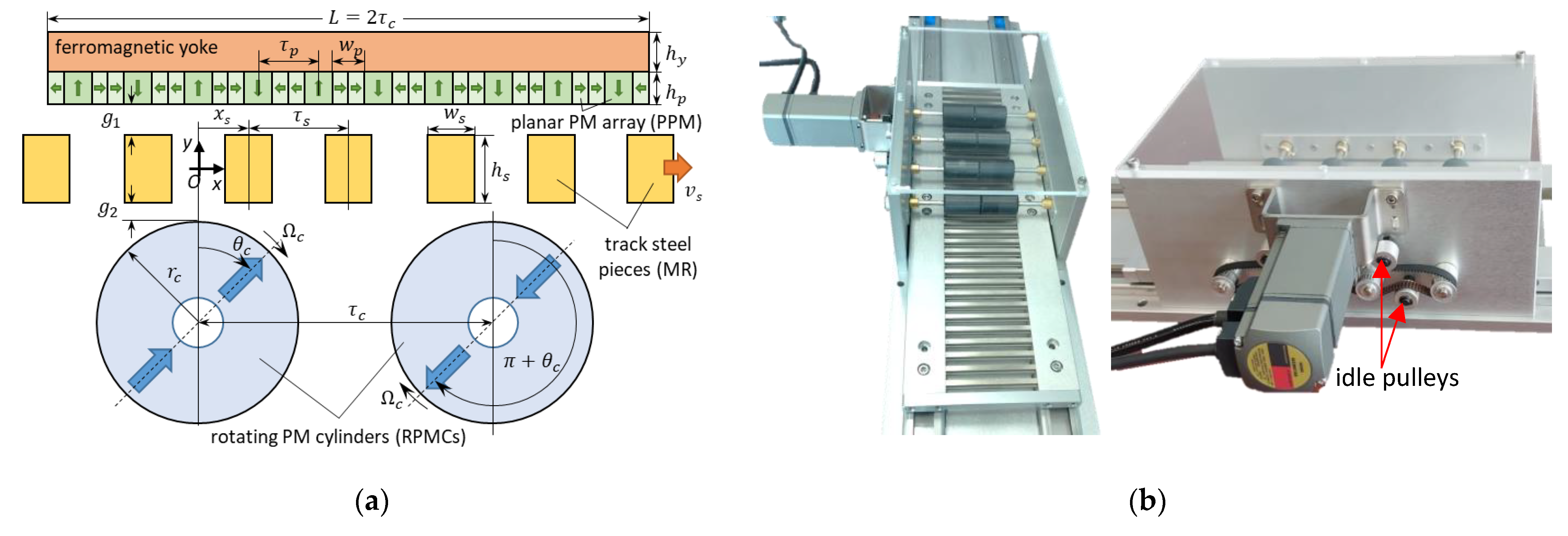
The proposed magnetic propulsion unit adopts a rotating to linear motion converter (RLMC) with an inherent MG effect. The basic module installed on-board (Figure 1a) consists of two PM arrays. A pair of PM cylinders (RPMCs) rotating synchronously at the speed generate a translating -pole pairs magnetic field. A set of planar PMs (PPMs) having -pole pairs interacts with the RPMCs because of the magnetic field modulation produced by a stationary magnetic rack (MR). The latter consists of steel pieces (MRSPs) per each PPM array length [19].
The device provides a contactless power transmission, converting the low torque/high speed motion of the RPMCs driven by conventional rotating motors to the high force/low speed vehicle motion. With respect to a total linear machine, the travelling magnetic field generated by the PM cylinders is less affected from well-known worsening end effects typical of short stator linear winding configuration [20]. Furthermore, the RLMC does not require supply systems, easing the installation and lowering the PPM heating.
The elimination of the rack-pinion devices leads to quieter, more efficient, and reliable operation, with remarkably less stringent requirements for the transmission interface coupling at the same time. The augmented adhesion allowed by contactless transmission, the adaptability to different routes and payloads thanks to the inherent modular design. easy and straightforward thrust control capability (propulsion and braking) by a conventional high-speed drive are favorable features of this propulsion system for vehicle operation on steep grade routes.
Figure 1b shows prototype under construction with 2 modules, developed for a small scale application with moving MRs and fixed RPMCs and PPM [21], currently under test to validate the results obtained by the proposed model. The MRs joined by an aluminum frame slide along a linear guide, dragged by the RPMCs rotation. The rotating motor drives the RPMCs by a timing belt-pulley arrangement applied to the RPMC shafts. Though some additional friction losses should be expected, cogged V- or synchronous belts relies on a well assessed technology, presenting an efficiency higher than 95% [22]. A pair of bearings integrated in the lateral holding plates support the RPMC shafts to ensure the air-gap width tolerances sustaining the attractive forces between the PM arrays and the MR. In the right-side Figure 1b picture, the idle pulleys, increasing the belt contact arc around the driving pulleys, can be clearly identified.
In the paper, the RLMC is sized to cope with the requirements for a low-capacity service on a short-distance sloped route. First, the feasibility of the propulsion system using multiple basic modules is assessed. The study based on magnetostatic finite element analyses (FEAs) aims to define the values of the main geometric parameters that fulfill the requested thrust and limit the thrust and torque ripple. Then, an improved design is carried out by examining different arrangements of reduced-size RPMCs, aiming at the enhancement of the dynamic performances and at the reduction of the torque ripple. For a more comprehensive performance evaluation, a procedure for the calculation of the electromagnetic losses is developed, based on time effective transient FEAs of a reduced geometric model. Such analyses enable to optimize the shape of the MRSPs and to determine the electromagnetic performances as functions of speed and load angle, used to estimate the size of the on-board energy source.
3. Application and RLMC Data
The considered application for the RLMC concerns the propulsion of a low-speed vehicle operating on a short length sloped route with a rail guideway. The assumptions for the main vehicle and performance characteristics are reported in Table 1, which somewhat recall a funicular service on mountain or in the urban environment.
The total mass includes the cabin, the supply, and the propulsion systems, as well as the payload. The maximum requested thrust must fulfill the resistance to motion (wheel-rail rolling, friction) as well as the inertial component requested to apply the maximum acceleration . In addition to the vehicle mass, an additional inertial factor must be considered to include the RPMC rotating mass:
with RPMCs per module and single RPMC inertia.
The preliminary design is based on the relations that provide the best transmission capacity at synchronized operation derived from the conventional theory of the CMG [2]:
with gear ratio and RPMC pitch. Assuming the basic module configuration ( = 1) and given , and , and are determined by (2) and , and are defined as well.
Table 2 shows the data assumed for the RLMC design. The RPMC speed is set aiming at the use of standard commercial motors. The chosen value enables a simplified manufacturing of the active parts and matches the condition for a favorable CMG design as for the volumetric torque density [23]. The active length and depth define the total available area for the module arrangement.
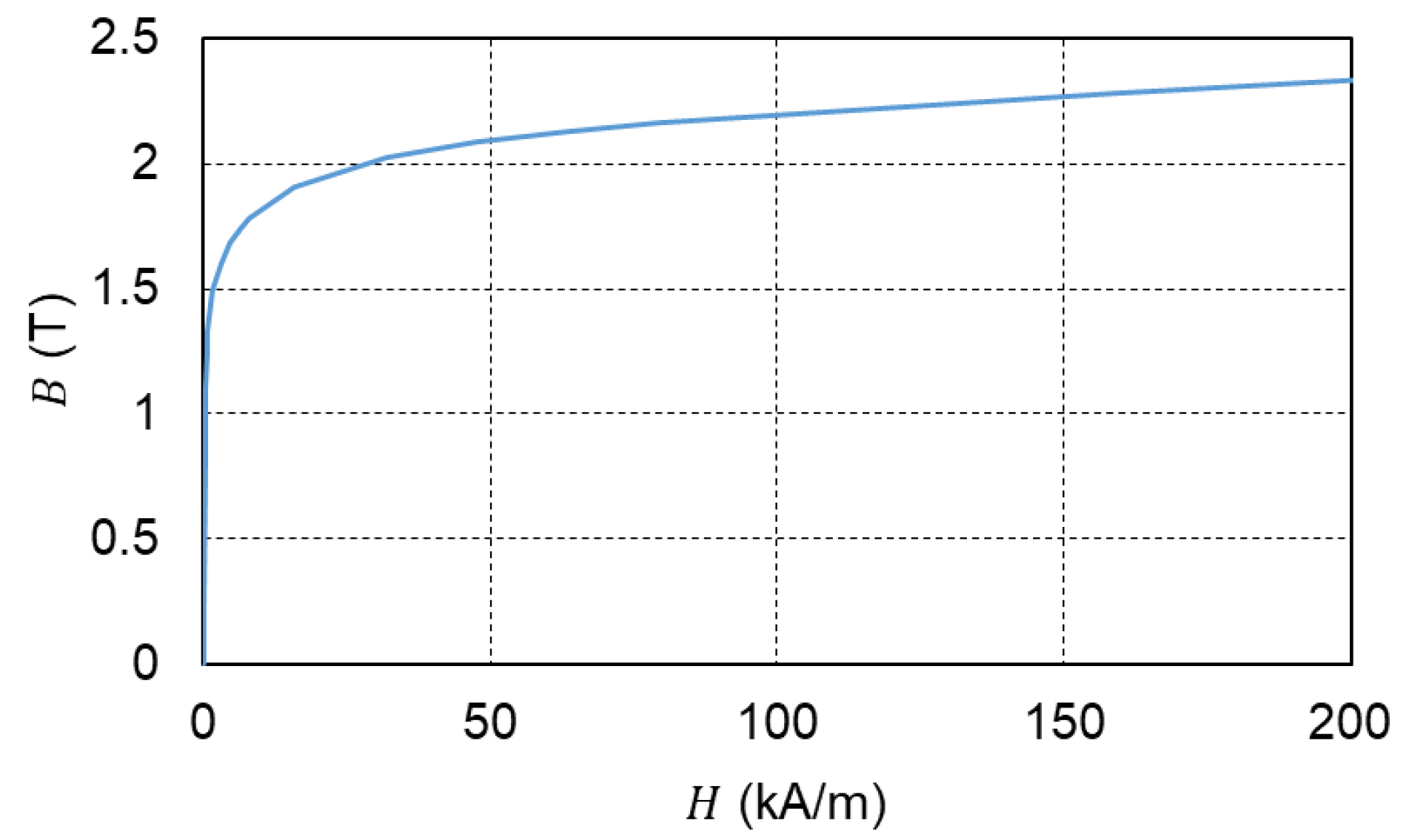
As for the material properties, ferrite PMs are adopted for their low cost, negligible electrical conductivity, and lower attractive force. The magnetization patterns are diametral for the RPMCs and quasi-Halbach type for the PPM. The ferromagnetic parts have the same material property (AISI 1008 Carbon Steel), considering a laminated stack for the PPM yoke and solid bars for the MRSPs, the latter to ease the core manufacturing and assembly. The BH characteristic is shown in Figure 2. The low frequency operation and the simple MRSP shape do not justify the adoption of high performing materials like soft magnetic composites [5,7] that, on the other hand, are much more expensive and can give rise to mechanical strength issues.
4. Preliminary Sizing of the RLMC
The RLMC sizing is based on a preliminary analysis which aimed to identify a convenient range for significant design ratios focusing on the thrust and the torque behavior at synchronized operation [19]. Let the mean total thrust, and torque tc the per unit (pu) depth thrust and total torque, respectively, with mean values and and standard deviations and , a set of performance indices are defined to achieve a profitable design:
with and total PM and device volumes and l*d the effective active depth to achieve the rated value of . The ripple indices and take into account the thrust/torque unevenness and the thrust densities , are related the PM and volume utilization, impacting on cost and system capacity.
The sizes of the basic module shown in Table 3 are obtained considering 5 in line modules to fulfill the maximum length constraints ( 2 m). Some parametric analyses are carried out by 2D magnetostatic FE code (Ansys Maxwell®) to tune the PM and MRSP sizes starting from some reference values obtained in [19].
Suitable meshes are set up by the code built in procedure, aimed to achieve a suitable refinement in the air-gap regions (about 40,000 triangles each in the MRSP and RPMC regions). The following results are obtained:
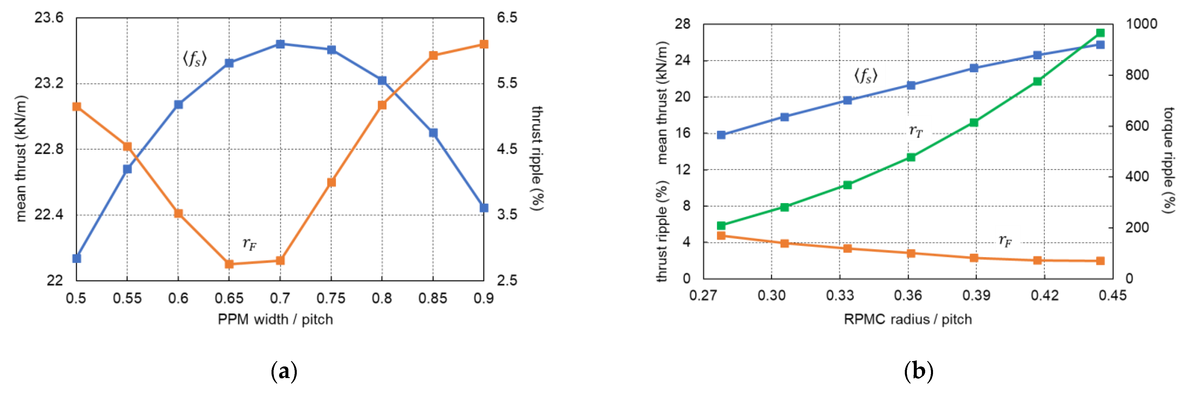
- The ratio 0.7 maximizes with minimum (Figure 3a), substantially confirming the convenience of choosing its value in the range [0.6:0.7].
- The variation of the MRSP parameters and in the ranges [0.34:0.46] and [1.2:2.2], respectively, mainly affects the thrust profile; increases as both ls and decrease, on the contrary depends mainly on , decreasing as decreases.
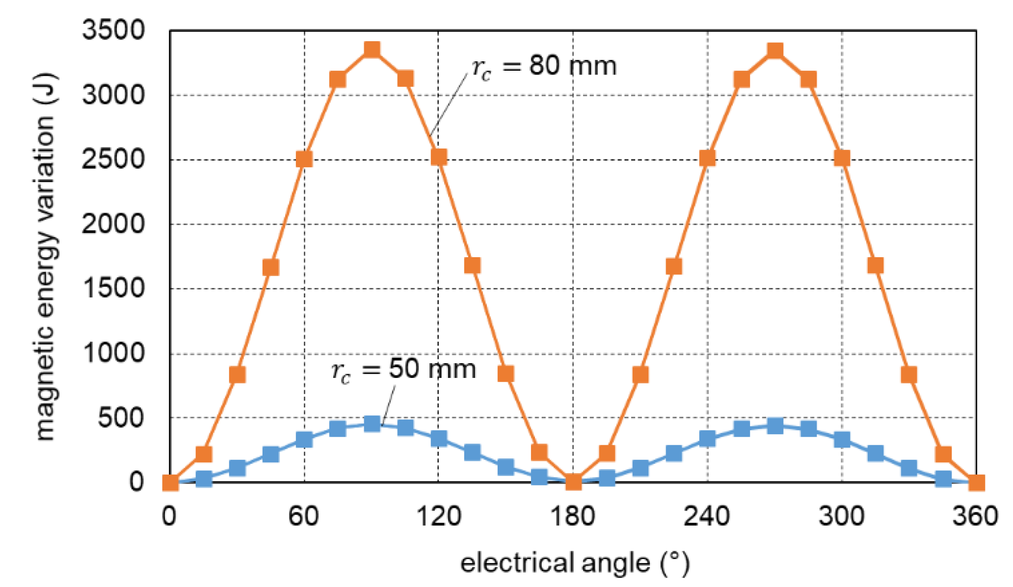
Established according to the above observations, the values in Table 3 ensure a favorable trade-off to fulfill the thrust performances in terms of usable active depth and thrust ripple ( 0.19 m, 2.7%). The torque ripple ( 620%) and the inertial factor ( 4.5) are, however, still too high. The former derives from the alternately magnetizing and demagnetizing interaction between adjacent RPMCs which produces large magnetic energy variations. This issue is checked considering the energy balance during a full RPMC rotation, assuming no losses:
with total magnetic energy variation, RPMC input energy and MRSP converted energy. Whether the energy terms related to the torque and force mean values cancel each other, represents the torque oscillating contribution. Figure 4 reports the evaluation for two RPMC radii, denoting the presence of a 2nd harmonic component strictly related to the magnetization interaction and the remarkable reduction of its amplitude by decreasing the RPMC radius. The same figure shows the agreement between the calculation by (4) and by direct FEAs.
The relevant torque ripple could lead to unacceptable stresses on the mechanical drive components. The high inertial factor, strictly depending on the exceeding RPMC diameter to fulfil the thrust requirement, impairs on the other hand the acceleration capability. Therefore, further design improvements are examined to mitigate such unfavorable occurrences.
5. Performance Improvement
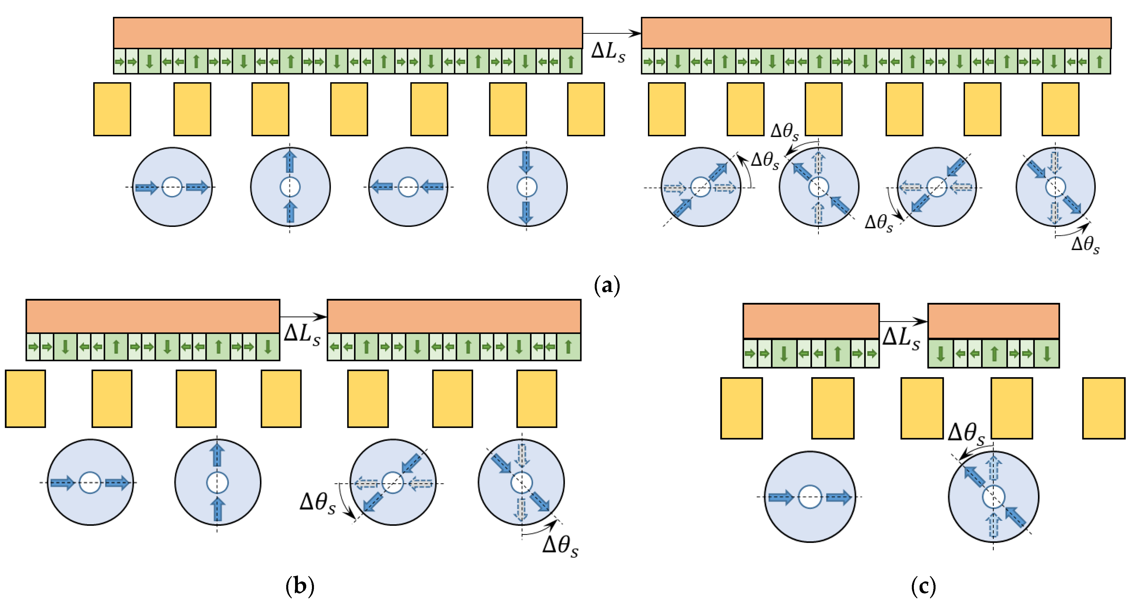
A substantial revision of the magnetic configuration is necessary to reduce the RPMC radius without impairing the thrust performance, as shown in Figure 3b. To such purpose, a quasi-Halbach configuration of the RPMCs is devised, interposing additional RPMC with 90° shifted magnetizations. Despite a slightly more complicated mechanical transmission due a doubled RPMC number, such arrangement enables a more effective volume exploitation with an overall PM material saving with respect to the basic module configuration. Preliminary FEAs evidence that a halved RPMC radius ( 35 mm) ensures the same thrust with 35% PM amount saving, dropping at the same time the inertial factor to 0.5, within Table 3 constraint.
For a further mitigation of the torque ripple, achieved with the new arrangement, the RPMC interaction must be even more weakened, and the oscillations of single RPMC torque profiles should be better counterbalanced. The early RPMC pairs are therefore split into multiple propulsion units, evenly displaced by the distance . At the same time, an additional anticlockwise rotation must be jointly applied to the adjacent displaced RPMCs to keep the electromagnetic RPMC-PPM field interaction synchronized (Figure 5). Three possible arrangements for the modules are considered consisting of 4 (conf. A), 2 (conf. B), and 1 (conf. C) RPMCs.
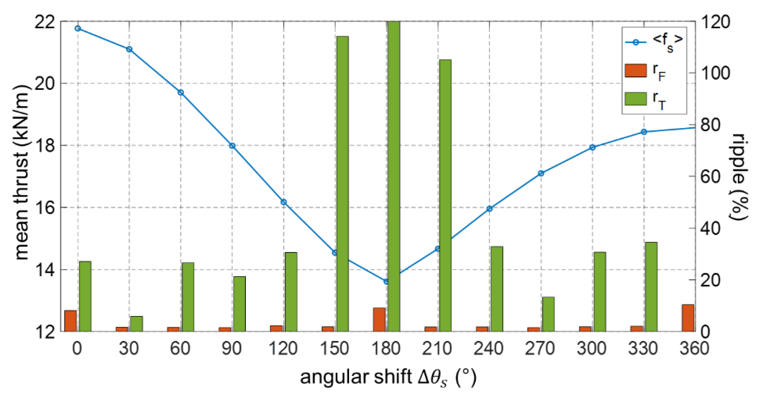
As an example, Figure 6 shows the thrust and torque indices as functions of for the conf. B. It can be noticed the significant ripple reduction with a limited rotation without an appreciable worsening of the pu length thrust and a consequent limited increase of the active length , satisfying the active length constraint.
Analogous studies were carried out for the other configurations to find the most profitable value for . Table 4 summarizes the corresponding performance indices, also including the calculations for the preliminary design and for the conf. A with null module distancing (i.e., 0°) for the sake of comparison. is the RLMC on-board mass obtained from the calculation of the depth by (3).
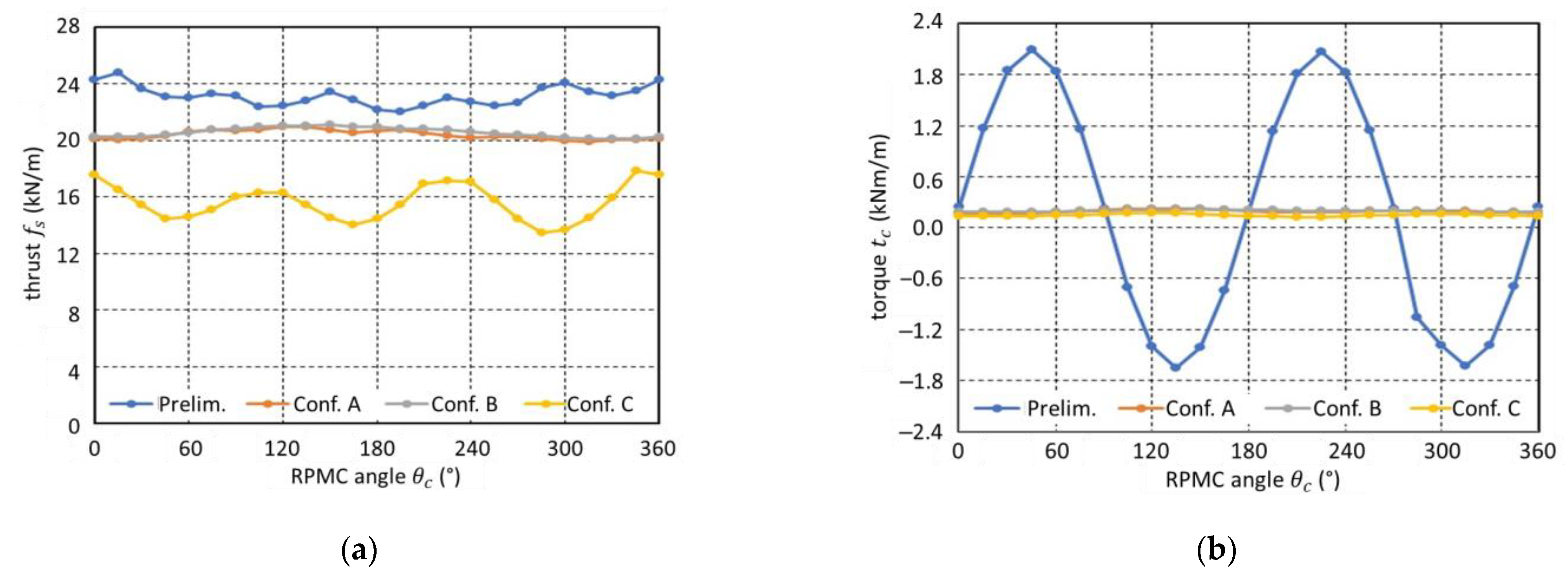
The conf. A with 0°, although the most convenient as for the thrust density and therefore with the lowest , yields unacceptable ripple values; the optimal choice remarkably decreases them with a limited reduction (−6%). The ripple is even lower for conf. B (−20%), the thrust density being almost unvaried. The single cylinder per module conf. C is generally worse as for general performances and mass requirement, due to the higher module distance necessary to limit the torque ripple, abating the mutual field reinforcement between adjacent RPMCs and therefore lowering the mean thrust. The comparison of the thrust and torque profiles (Figure 7) evidence the smoothing effects obtained by shifting the propulsion units and the advantage of conf. B with respect to the other configurations. It is worth mentioning that the module distancing contributes also to the reduction of the single RPMC torque ripple, as its average value is more than halved with respect to the preliminary device. The limited mass of the conf. B is another favorable feature for the examined application.
To increase the stiffness of the module, the effect of using a unique PPM yoke is also investigated. Though resulting in higher amount of ferromagnetic laminated material (+2.5%), the FEAs carried out on conf. B denotes a slight increase for the thrust (+1%) and a decrease for the ripple (−9%) as well as a notable decrease in torque ripple (−35%). This outcome is likely related to the enhanced focusing of the RPMC flux lines inside the module rather than leaking towards the adjacent ones.
6. Calculation Model
6.1. Electromagnetic Losses
A procedure for the evaluation of the electromagnetic losses is set up to assess the suitability of the material properties and to optimize the RLMC efficiency by choosing alternative MRSP shapes. The losses calculated at different speed values will also enable the estimation of the system energy requirements and consequently the size of the on-board source. The loss contributions per unit volume, computed with reference to synchronized operation by 2D FEAs, are:
- Eddy current losses in the solid MRSPswith steel resistivity and magnetic vector potential.
- Eddy current losses in the PPM laminated yokewith eddy current loss coefficient and time variation of the and flux density components.
- Hysteresis losses in the MRSPs and PPM yoke (averaged over a flux density cycle)with instantaneous flux density value, period related to the flux density cycle, hysteresis loss coefficient, coefficient considering the DC-biased induction component , corresponding to averaged over T, [24]; they are evaluated by an internal procedure of the FE code.
The coefficients and related to the classical Steinmetz equation are determined by processing the core loss curves at different frequencies by a FE built-in interpolation routine. The values for the chosen steel material related to 0.5 mm lamination thickness are presented in Table 5, also including the stacking factor. As a reference, the specific core losses at 50 Hz, 1.5 T is given. For this kind of material, the routine provides negligible excess loss contribution, which is generally present in the modified Steinmetz equation. Values are related to standard room temperature and dependence on temperature is neglected. The resultant eddy current and hysteresis losses for the MRSPs and for the PPM yoke, respectively, are obtained by volume integration of the loss densities in the corresponding cross-section of the material.
6.2. Reduced Geometric Model
With reference to the conf. B, a preliminary simplified approach relies on analytically reproducing , and by the elaboration of the results of automated magnetostatic FEA sequences. The large size of the geometric model caused by the absence of magnetic periodicity and the need to consider several MRSPs positions could lead to a remarkably lower calculation time in comparison with FEA transient simulations, in principle essential to evaluate the MRSP eddy current losses . However, the above approach cannot consider the relevant eddy current effect on air-gap field.
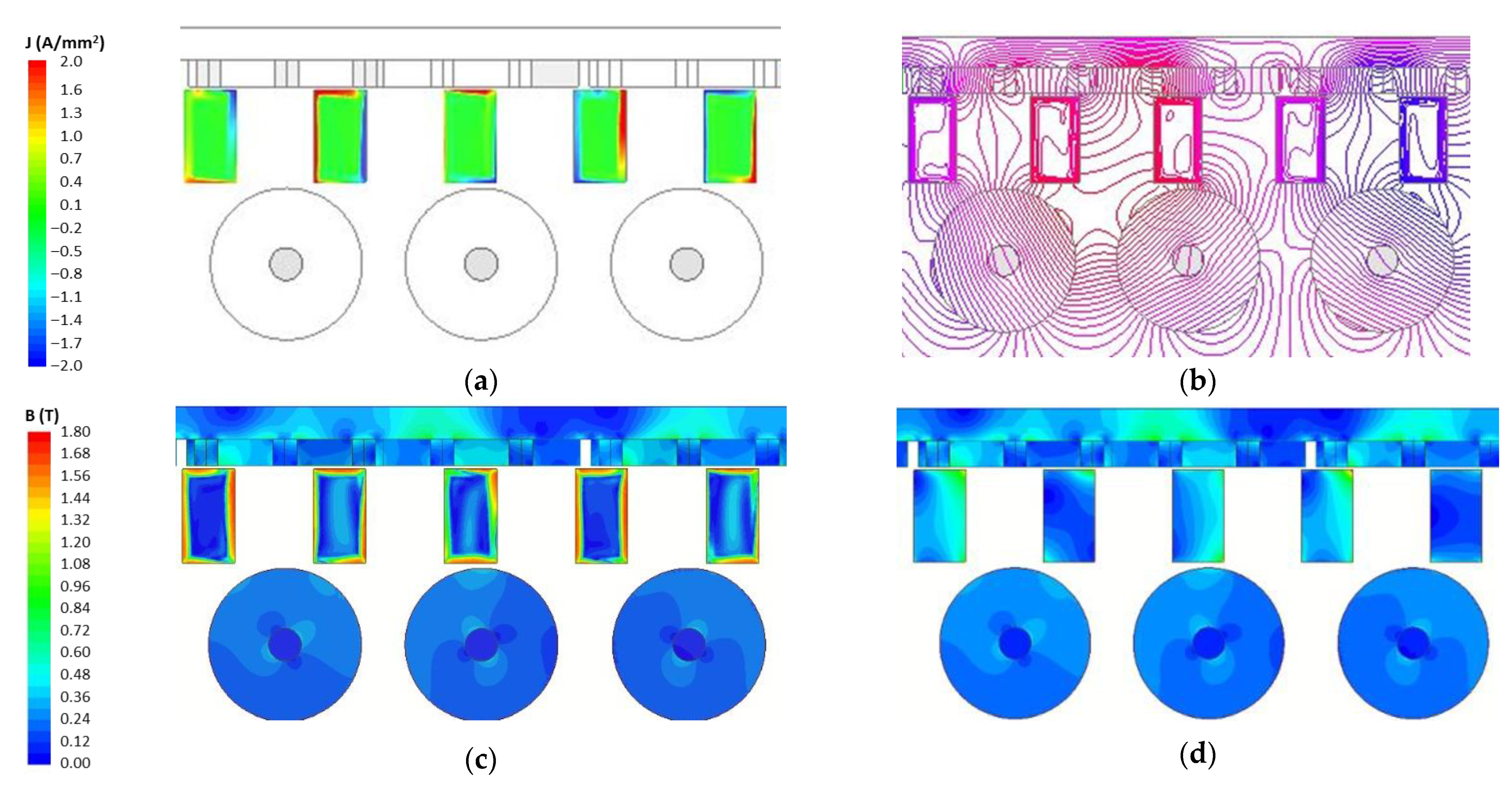
According to the transient FEA, the higher values of the current density are concentrated at the MRSP borders (Figure 8a), producing a shielding effect on the flux lines (Figure 8b). The flux density map is therefore remarkably altered with respect to a magnetostatic solution as shown in Figure 8c,d. Moreover, the use of the magnetostatic FEAs would not enable to determine the reduction share on the thrust due to the MRSP losses, which contribution is as a matter of fact split into both thrust and torque reduction.
Therefore, an alternative procedure is developed that consists of the execution of transient FEAs on a reduced geometric model, derived as a subset of the original configuration. It relies on the fact that, under synchronized conditions, each single MRSP undergoes the same thrust and electromagnetic losses, albeit time shifted. The same deduction applies to each PPM yoke region. Then, the analysis can be restricted to a single MRSP and PPM yoke section, provided that the electromagnetic effects on MRSPs during their motion in the entry and exit regions as well as in the intermediate zone (transition) between RPMCs and PPMs are reproduced with acceptable accuracy.
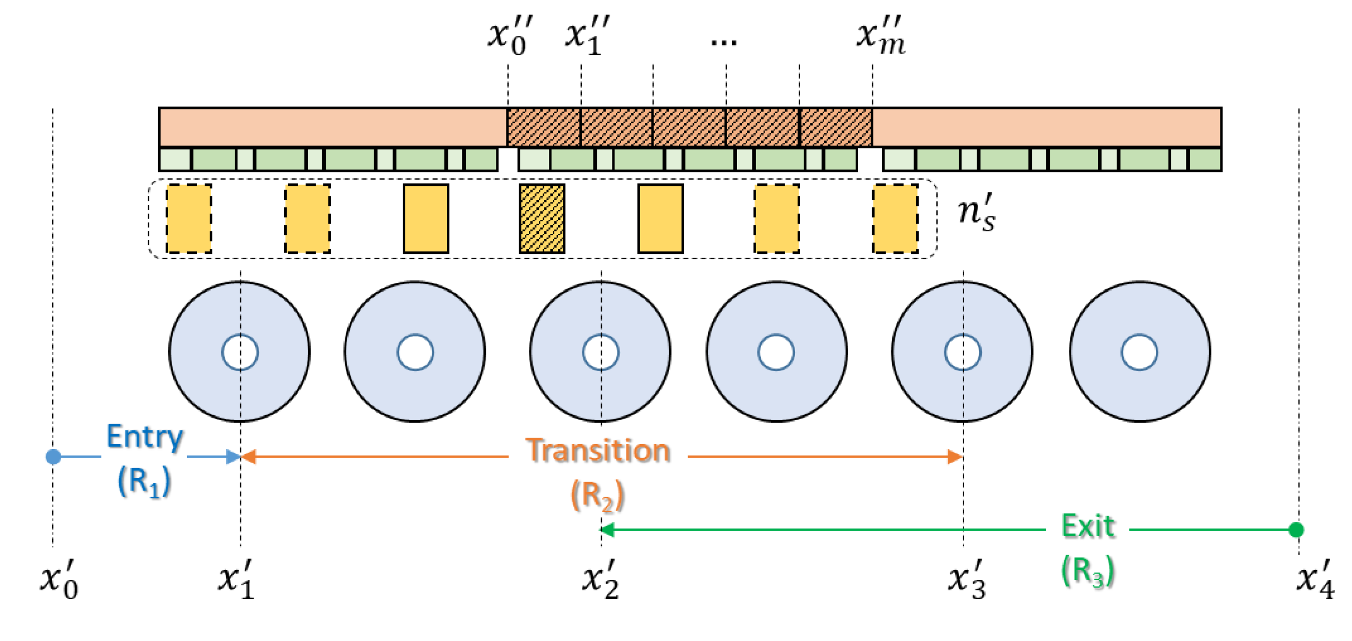
To this purpose, the reduced model in Figure 9 is considered, consisting of three RPMC modules and an odd subset of MRSPs, moving across the RPMC modules. Even if the magnetic field distribution is evaluated on the whole model, only the results related to the reference objects (identified by hatching) are post-processed. In particular, the instantaneous thrust and losses are calculated only for the middle MRSP of the subset (index , to include the adjacent MRSPs proximity influence) and for the central PPM yoke, limited to the positions where the MRSPs subset completely face the yoke. The solution domain downsizing significantly reduces the computational effort since only the area restricted to the reference objects needs an extreme mesh refinement, a limited set of the field data is elaborated, and the time sampling during the transient solution can be adapted according to the reference MRSP position.
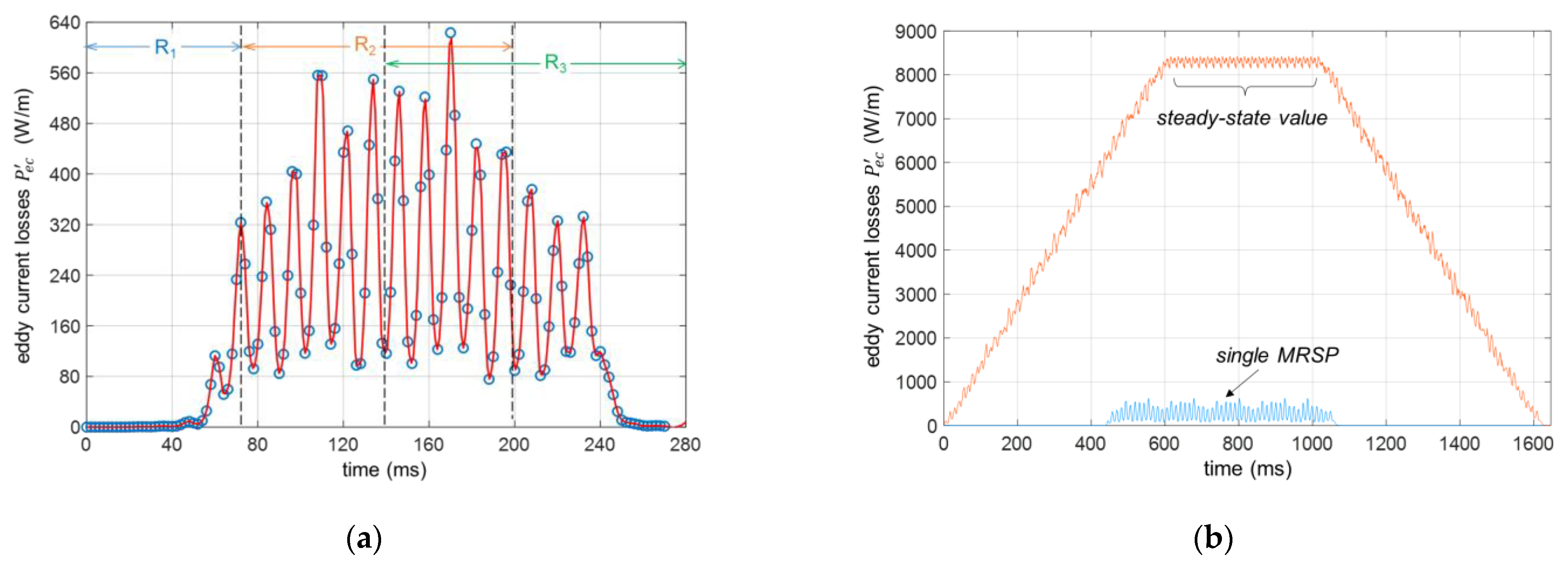
The reference MRSP position coordinates enable to define three position ranges ( 1,2,3) for the elaboration of the instantaneous MRSP quantities. They are related to the motion inside the inner modules () and in the entry and exit regions (position ranges and , respectively), where the end effects affect the electromagnetic quantities. To avoid discontinuities in passing from to , the exit region is wider than the entry one. The instantaneous profiles are obtained first by a suitable joining process of the data sequences related to the different position ranges and then applying a spline interpolation. Figure 10a shows the pu length losses with 7, highlighting the time intervals related to the regions . The dissymmetry between the entry and exit effects is evident, as the latter is affected by eddy current circulation for longer time likely due to the greater number of RPMCs involved.
Let the instantaneous value of the generic MRSP quantity in the range , the resultant curve is obtained from the following elaborations:
- The profile of the transition zone is replicated times to reproduce the actual length of the complete model; the resultant profile for the reference MRSP is then given by:The number derives from the adopted range subdivision .
- The curves ( 1…, ) related to the MRSPs travelling in the range during a stroke length, are superimposed to obtain the resultant instantaneous value
Figure 10b shows the result of the elaboration procedure. The blue trace represents the profile of a single MRSP obtained by (8); the orange trace represents the superposition of profiles related to each MRSP, identical to the former one and shifted from each other by , according to (9). The total average value is evaluated with reference to the steady-state interval with the contribution of all the MRSPs.
Regarding the PPM losses, the central yoke section is subdivided into regions delimited by the coordinates ( 0…, ) related to the corresponding positions of the MRSP subset. To correctly reproduce the evolution of the losses, each region must be completely covered by the MRSPs. Therefore, the evaluation for the -th region starts when the first MRSP is at and ends when the MRSP is at , obtaining k time shifted curves. The total average values of the PPM core losses are then given by:
with calculation time for the -th region, instantaneous eddy current losses, and cumulative value of the hysteresis losses.
The above procedure does not enable to evaluate the instantaneous torque since it depends on the interaction among the RPMCs of the whole model. Let the total losses with , , the mean torque and the electromagnetic efficiency can be calculated from the power balance as:
6.3. Check of the Reduced Model Results
Table 6 shows the values of the main electromagnetic quantities calculated by the full and the reduced models, considering for the latter 5, 50 and different number . To evaluate the computational effort for the FEAs, the number of triangle elements of the mesh and the solution time are also reported, the latter assessed adopting the same hardware. Provided that 3, there is a general good agreement, as for accuracy of loss and efficiency calculation. With 5, the deviations are very limited (−2.7% for , −5.6% for ) with computation time reduced more than three times. The deviations with 7 are practically negligible with respect to the full model, with a considerable time saving anyway.
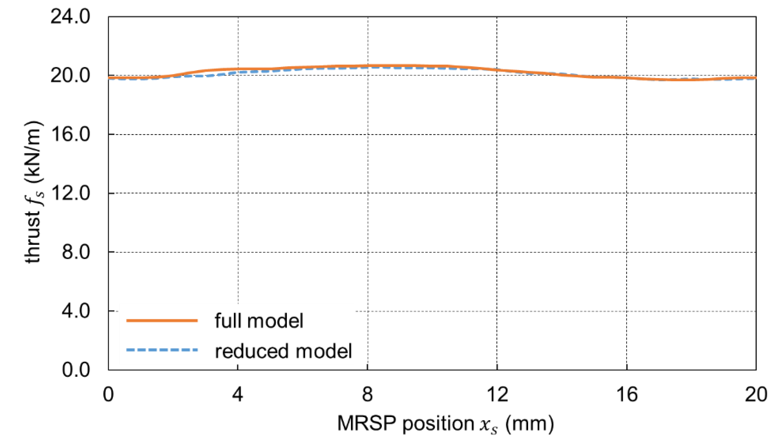
The accuracy is also confirmed by the comparison of the instantaneous thrust values in Figure 11, so this procedure is also effective to evaluate the thrust ripple. According to these results, the reduced model can be used for parametric/optimization analyses without exceedingly time-consuming transient analyses.
7. Optimization of the MRSP Cross-Section
The results in Table 6 evidence the need to improve the efficiency of the system by decreasing RLMC losses. The largest share is due to the MRSP eddy current losses ( 93% ) related to the solid material structure.
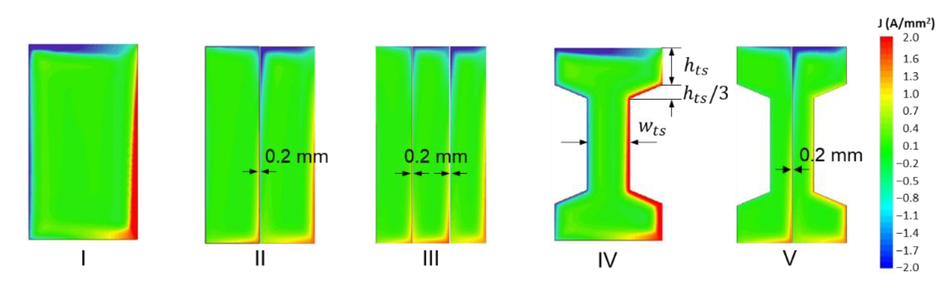
The MRSP cross-section shaping and its subdivision in insulated parts were investigated to reduce , the PM array size and arrangements being unvaried. The examined options are shown in Figure 12. The initial rectangular cross-section (type I) is divided in two and three parts (types II and III) separated by 0.2 mm insulation thickness; an additional segmentation can lead to higher costs of production as well as the magnetic saturation of the tiny slabs. As an alternative, an IPE beam-like shape is also considered (type IV and V), obtained by removing some material at the middle sides of the section without detriment to the MRSP robustness and to the magnetic operating point. The convenience of this shape for the torque transmission capability was already verified for the CMGs [25].
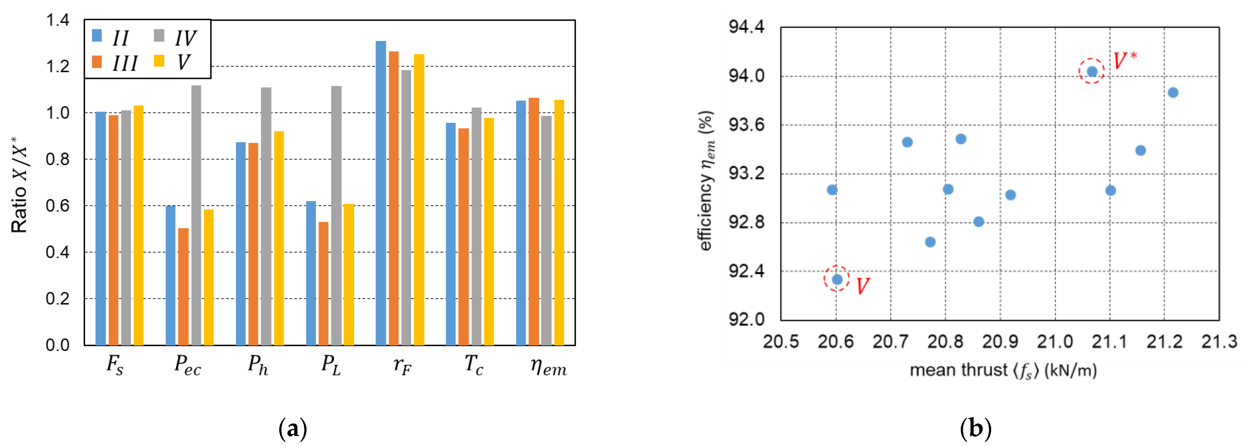
The eddy current density distributions in Figure 12 are obtained by the reduced model with 7 at the same instant for all the MRSP types. The much more restricted regions at higher highlight the convenience of the MRSP segmentation. A more comprehensive analysis was carried out involving the comparison of some relevant RLMC performances to select the most convenient configuration. To this purpose, the calculated quantities were compared in the pu form , with value of the corresponding quantity for the type I.
Figure 13a evidences a remarkable decrease of the total losses mainly for the type III, leading to a significant efficiency improvement (from 87.1% to 92.6%). In contrast, type IV presents slightly higher losses despite the material reduction, likely related to higher flux density values. The thrust is almost unchanged for all types, denoting that eddy currents have a limited braking action on the moving part.
Conversely, the torque evaluated by (11) is inherently affected by the losses, implying a slight deterioration for the type IV. The ripple increases for all the types, however, within a satisfactory range (from 1.6% to a maximum 2.1% for the type II). Taking also into account the material saving, the type V can be assumed as the best trade-off between the evaluated performances. Table 7 proves the overall improvement achieved from such an analysis. The input mechanical power is reduced by ≈ 7% and the depth l*d by ≈ 5%, with a consequent reduction the on-board mass.
The suitability of such a configuration being confirmed, a parametric analysis investigated the influence of the sizes and , the total height hs and width being unchanged. The purpose is to increase the resistance of the eddy current paths, without negatively affecting the magnetic saturation and consequently thrust and hysteresis losses. In total, 12 variable sets were examined starting from the values 4.7 mm, 9.6 mm and gradually reducing both the quantities excluding too low values (<3 mm) for manufacturing feasibility.
The values of the efficiency and the pu depth mean thrust are reported in Figure 13b, indicating also the value related to the type V. There emerges a general improvement, mainly for the further reduction of the eddy current losses. The type V* was selected as the optimal one, since it provides the highest efficiency with increased thrust (+3.6%) with respect to the type V. The data reported in Table 7 evidence the relevant and reduction (−30% and −12%, respectively). Much thinner cross-sections could lead to an additional decrease at the expense of lower thrust and MRSP strength. The achieved efficiency is highly satisfactory, assessing the suitability of the proposed propulsion system.
8. Dynamic Performances
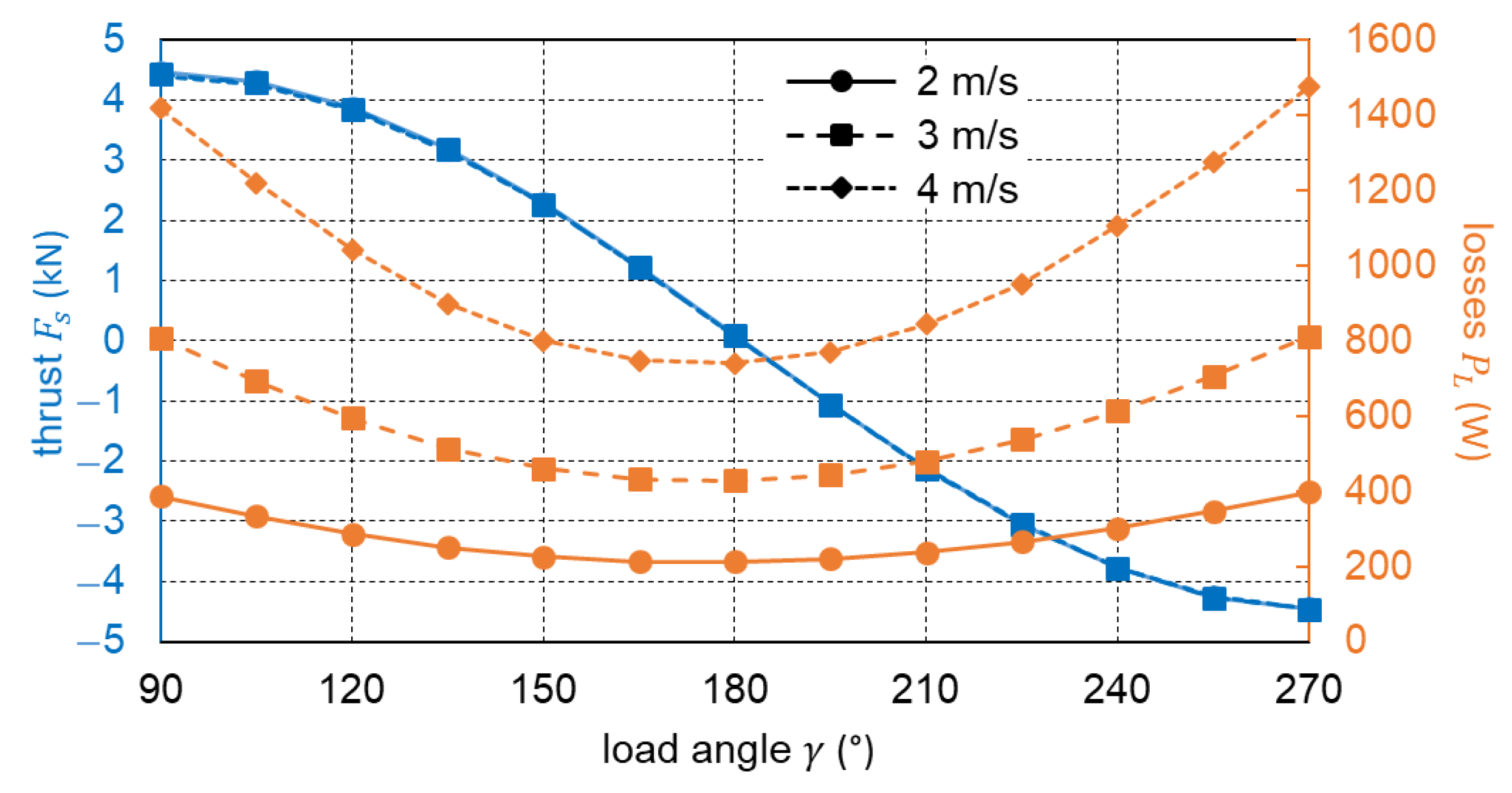
The performances of the optimized configuration as functions of the load angle and speed can now be determined to predict the energy consumption and recovery for a given the service speed trace , with the purpose to size the on-board energy source, e.g., a battery. The mean thrust and the total losses, directly involved in the system dynamic equation, are shown in Figure 14: it is worth remarking that , independent of speed, can be adjusted by varying the load angle , i.e., the displacement between RPMC angle axis and the electrical angle associated to the MRSP position . The highest losses are associated to the maximum thrust absolute values, generally occurring during the acceleration/braking phases.
The required thrust profile is ruled by the dynamic equation on a sloping route, expressed as
with gravity force due to the slope, friction component (assumed to be a constant, speed dependence being negligible due to low-speed operation), and inertial mass that includes the rotating part contribution. Assuming the motor drive delay negligible with respect to the motion dynamics, the profile is defined by solving the equation , with given by (12); then, the instantaneous losses are determined. The motor drive input power is
with the drive average efficiency including mechanical losses. The net energy requested to perform ntrip ascent and descent daily trips can be broadly estimated as:
with energy requested from auxiliary services, the drive power during the traction and braking phases and , the source average efficiency during discharge and recharge processes.
Using the data in Table 1 and the calculated RLMC characteristics, the energy and the battery mass were evaluated with reference to some typical technical data reported in Table 8. The battery energy density refers to current Li-ion technology data [26]. The results 28 kWh and =140 kg are consistent with autonomous vehicle operation, though the demanding service related to the sloped route. It is worth noting that the cycle energy efficiency (traction and braking phases) of the RLMC is about 93.6%, resulting in an overall system efficiency of about 74%. A homogenous comparison with a conventional ropeway transportation is rather difficult depending on the influence of several parameters (plant size and capacity, technology, and operational strategies); however, some studies estimate the average efficiency of such systems as much as 50%, where the main share of the power dissipation is related to rolling resistance of sheaves/rollers and bull-wheels (≈ 40%) [27]. Then, the proposed transport system could benefit from a more efficient operation even for routes with an appreciable slope.
9. Conclusions
The proposed magnetic device integrates the features of a conventional magnetic gear with a contact-less rotating to linear motion enabling to drive efficiently and reliably linear moving loads. The possibility of using conventional rotating equipment, inexpensive and low environmental impact passive guideway and cost-effective magnetic materials gives a significant advantage with respect to other proposed magnetic gear configurations and suggest a profitable application for vehicle propulsion systems, especially if operating on sloped routes. Furthermore, the motion transmission from the rotating motor drive to the RPMCs can be conveniently implemented by well-assessed, reliable, and efficient timing belt and pulley devices, sheltered in an accessible on-board volume, unlike rack-pinion gear or funicular based transport systems, wear prone and requiring heavy maintenance.
The design procedure developed in the paper enabled a detailed evaluation of the feasible performances (in particular, thrust, torque, and efficiency) for various configurations thanks to the time effectiveness and accuracy of the simplified analysis on a reduced model. As a result, an optimization process was successfully applied to define the RPMC and MRSP arrangement, yielding the dynamic ratings of a practical application with low torque and thrust ripple and very limited losses.
The same simplified analysis enabled the elaboration of RLMC characteristics as functions of the load angle and speed to predict the system energy demand. Referring to a realistic application scenario, the on-board source energy requirement is therefore assessed. The obtained specifications are consistent with ordinary commercial applications. At the same time, the overall estimated efficiency is appreciably higher in comparison to conventional ropeway transportation.
Author Contributions
Conceptualization, M.A. and A.T.; methodology, M.A. and A.T.; software, S.B.; formal analysis, M.A.; investigation, S.B. and A.T.; data curation, S.B.; writing—original draft preparation, A.T.; writing—review and editing, M.A. and S.B.; supervision, M.A. and A.T.; funding acquisition, A.T. All authors have read and agreed to the published version of the manuscript.
Funding
This research was funded by Department of Industrial Engineering—University of Padova, Project ID TORT_SID19_01.
Data Availability Statement
Data available on request.
Acknowledgments
The authors thank Mate srl for the realization of the preliminary prototype.
Conflicts of Interest
The authors declare no conflict of interest.
References
- Tlali, P.M.; Wang, R.-J.; Gerber, S. Magnetic Gear Technologies: A Review. In Proceedings of the International Conference on Electrical Machines (ICEM), Berlin, Germany, 2–5 September 2014. [Google Scholar]
- Atallah, K.; Howe, D. High-performance magnetic gears. J. Magn. Magn. Mater. 2004, 272–276, e1727–e1729. [Google Scholar] [CrossRef]
- Chen, Y.; Fu, W.N.; Ho, S.L.; Liu, H. A Quantitative Comparison Analysis of Radial-Flux, Transverse-Flux, and Axial-Flux Magnetic Gears. IEEE Trans. Magn. 2014, 50, 8104604. [Google Scholar] [CrossRef]
- Desvaux, M.; Chauwin, M.; Multon, B.; Sire, S.; Ahmed, H.B. Experimental validation of a transverse flux magnetic gear. J. Magn. Magn. Mater. 2021, 536, 168139. [Google Scholar] [CrossRef]
- Bomela, W.; Bird, J.Z.; Acharya, V.M. The Performance of a Transverse Flux Magnetic Gear. IEEE Trans. Magn. 2014, 50, 4000104. [Google Scholar] [CrossRef]
- Acharya, V.M.; Bird, J.Z.; Calvin, M. A Flux Focusing Axial Magnetic Gear. IEEE Trans. Magn. 2013, 49, 4092–4095. [Google Scholar] [CrossRef]
- Andriollo, M.; Graziottin, F.; Tortella, A. Design of an Axial-Type Magnetic Gear for the Contact-Less Recharging of a Heavy-Duty Bus Flywheel Storage System. IEEE Trans. Ind. Appl. 2017, 53, 3476–3484. [Google Scholar] [CrossRef]
- Li, W.; Chau, K.T.; Lee, C.H.T.; Ching, T.W.; Chen, M.; Jiang, J.Z. A new linear magnetic gear with adjustable gear ratios and its application for direct-drive wave energy extraction. Renew. Energy 2017, 105, 199–208. [Google Scholar] [CrossRef] [Green Version]
- Yin, X.; Pfister, P.-D.; Fang, Y. A Novel Magnetic Gear: Toward a Higher Torque Density. IEEE Trans. Magn. 2015, 51, 8002804. [Google Scholar] [CrossRef]
- Li, X.; Chau, K.-T.; Cheng, M.; Hua, W. Comparison of Magnetic-Geared Permanent Magnet Machines. Prog. Electromagn. Res. 2013, 133, 177–198. [Google Scholar] [CrossRef] [Green Version]
- Rasmussen, P.O.; Frandsen, T.V.; Jensen, K.K.; Jessen, K. Experimental Evaluation of a Motor-Integrated Permanent-Magnet Gear. IEEE Trans. Ind. Appl 2013, 49, 850–859. [Google Scholar] [CrossRef]
- Shin, H.; Chang, J.; Hong, D. Design and Characteristics Analysis of Coaxial Magnetic Gear for Contra-Rotating Propeller in Yacht. IEEE Trans. Ind. Electr. 2020, 67, 7250–7259. [Google Scholar] [CrossRef]
- Wong, H.Y.; Baninajar, H.; Dechant, B.; Bird, J. Designing a Magnetic Gear for an Electric Aircraft Drivetrain. In Proceedings of the IEEE Energy Conversion Congress and Exposition (ECCE), Detroit, MI, USA, 11–15 October 2020. [Google Scholar]
- Holm, R.K.; Berg, N.I.; Walkusch, M.; Rasmussen, P.O.; Hansen, R.H. Design of a Magnetic Lead Screw for Wave Energy Conversion. IEEE Trans. Ind. Appl. 2013, 49, 2699–2708. [Google Scholar] [CrossRef]
- Cirolini, M.; Flores Filho, A.F.; Wu, Y.C.; Dorrell, D.G. Design Aspects of a Reluctance-Based Magnetic Lead Screw. IEEE Trans. Magn. 2019, 55, 8001906. [Google Scholar] [CrossRef]
- Gao, F.; Wang, Q.; Hu, Y.; Chen, B.; Zhao, B.; Zou, J. Performance Evaluation of Magnetic Lead Screws Equipped with Skewed Arc Magnets Instead of Helical Ones. IEEE Trans. Magn. 2018, 54, 8204405. [Google Scholar] [CrossRef]
- Hoffmann, K.; Liehl, R. Cable-drawn urban transport systems. Wit Trans. Built Environ. 2005, 77, 25–36. [Google Scholar]
- Tischler, S.; Mailer, M. Cable Propelled Transit Systems in Urban Areas. Transp. Res. Procedia 2019, 41, 169–173. [Google Scholar] [CrossRef]
- Andriollo, M.; Saracino, F.; Tortella, A. Rotating to Linear Motion Magnetic Converter for Low-Capacity Transport Applications. In Proceedings of the XXII International Conference on Electrical Machines(ICEM 2016), Lausanne, Switzerland, 4–7 September 2016. [Google Scholar]
- Boldea, I. Linear Electric Machines, Drives, and MAGLEVs Handbook; CRC Press: Boca Raton, FL, USA; Taylor & Francis Group: Abingdon, UK, 2013; pp. 72–84, 96–97, 218–220, 301–303. [Google Scholar]
- Andriollo, M.; Bernasconi, S.; Tortella, A. Force and Torque Assessment in a Rotating to Linear Motion Magnetic Converter with Gearing Capability. In Proceedings of the IEEE Energy Conversion Congress and Exposition (ECCE), Vancouver, BC, Canada, 10–14 October 2021. [Google Scholar]
- De Almeida, A.; Greenberg, S. Technology assessment: Energy-efficient belt transmissions. Energy Build. 1995, 22, 245–253. [Google Scholar] [CrossRef]
- Johnson, M.; Gardner, M.C.; Toliyat, H.A.; Englebretson, S.; Ouyang, W.; Tschida, C. Design, Construction, and Analysis of a Large-Scale Inner Stator Radial Flux Magnetically Geared Generator for Wave Energy Conversion. IEEE Trans. Ind. Appl. 2018, 54, 3305–3314. [Google Scholar] [CrossRef]
- Simão, C.; Sadowski, N.; Batistela, N.J.; Bastos, J.P.A. Evaluation of Hysteresis Losses in Iron Sheets Under DC-biased Inductions. IEEE Trans. Magn. 2009, 45, 1158–1161. [Google Scholar] [CrossRef]
- Fujita, T.; Ando, Y.; Nagaya, K.; Oka, M.; Todaka, T.; Enokizono, M.; Sugiura, K. Surface Magnet Gears with a New Magnet Arrangement and Optimal Shape of Stationary Pole Pieces. J. Electromagn. Anal. Appl. 2013, 5, 243–249. [Google Scholar] [CrossRef] [Green Version]
- Cox, B.; Bauer, C.; Beltranc, A.M.; van Vuurend, D.P.; Mutel, C.L. Life cycle environmental and cost comparison of current and future passenger cars under different energy scenarios. Appl. Energy 2020, 269, 115021. [Google Scholar] [CrossRef]
- Szlosarek, R.; Yan, C.; Kröger, M.; Nußbaumer, C. Energy efficiency of ropeways: A model-based analysis. Public Transp. 2019, 11, 617–635. [Google Scholar] [CrossRef]
Figure 1.
(a) RLMC basic module; , xs: RPMC angular position and MR linear position with respect to the fixed reference frame Oxy; : MR relative speed and RPMC angular speed; (b) small-scale prototype under development with moving MR and stationary PPM and RPMCs ( = 2 modules).
Figure 1.
(a) RLMC basic module; , xs: RPMC angular position and MR linear position with respect to the fixed reference frame Oxy; : MR relative speed and RPMC angular speed; (b) small-scale prototype under development with moving MR and stationary PPM and RPMCs ( = 2 modules).

Figure 2.
Magnetic characteristic of the steel material.

Figure 3.
(a) pu depth mean value and ripple rF as functions of the ratio ( 70 mm); (b) pu depth mean value and ripples as functions of the ratio ( 25 mm).
Figure 3.
(a) pu depth mean value and ripple rF as functions of the ratio ( 70 mm); (b) pu depth mean value and ripples as functions of the ratio ( 25 mm).

Figure 4.
Magnetic energy variation during a full rotation of the RPMCs evaluated by the energy balance and direct FEAs (squared dots).
Figure 4.
Magnetic energy variation during a full rotation of the RPMCs evaluated by the energy balance and direct FEAs (squared dots).

Figure 5.
RPMC modules with quasi-Halbach magnetization; : shifting distance between adjacent modules ( corresponding angular shift of the magnetization); (a) 4 (conf. A); (b) 2 (conf. B); (c) (conf. C).
Figure 5.
RPMC modules with quasi-Halbach magnetization; : shifting distance between adjacent modules ( corresponding angular shift of the magnetization); (a) 4 (conf. A); (b) 2 (conf. B); (c) (conf. C).

Figure 6.
Thrust and torque performances as functions of the angular shift (conf. B).

Figure 7.
Comparison of the pu depth thrust (a) and torque (b) for different RPMC arrangements (Conf. A with 60°).
Figure 7.
Comparison of the pu depth thrust (a) and torque (b) for different RPMC arrangements (Conf. A with 60°).

Figure 8.
Maps of the electromagnetic quantities determined by the FEAs (same MR position); eddy current density (a), flux lines (b), and flux density (c) evaluated by the transient solver; flux density evaluated by the magnetostatic solver (d).
Figure 8.
Maps of the electromagnetic quantities determined by the FEAs (same MR position); eddy current density (a), flux lines (b), and flux density (c) evaluated by the transient solver; flux density evaluated by the magnetostatic solver (d).

Figure 9.
Geometric model adopted for the simplified transient FEAs with the position ranges and adopted for the elaboration of the MRSP and PPM quantities, respectively.
Figure 9.
Geometric model adopted for the simplified transient FEAs with the position ranges and adopted for the elaboration of the MRSP and PPM quantities, respectively.

Figure 10.
Pu depth eddy current losses in the MRSP calculated by the reduced model ( 7); (a) analysis related to a single MRSP; (b) resultant from the superimposition of the single MRSP profiles.
Figure 10.
Pu depth eddy current losses in the MRSP calculated by the reduced model ( 7); (a) analysis related to a single MRSP; (b) resultant from the superimposition of the single MRSP profiles.

Figure 11.
Pu depth thrust as a function of the position calculated by means of the full and the reduced models ( 7).
Figure 11.
Pu depth thrust as a function of the position calculated by means of the full and the reduced models ( 7).

Figure 12.
Map of the eddy current density for different MRSP cross-section shape (types I–V); 8.2 mm; 9.4 mm (type IV); 9.6 mm (type V).
Figure 12.
Map of the eddy current density for different MRSP cross-section shape (types I–V); 8.2 mm; 9.4 mm (type IV); 9.6 mm (type V).

Figure 13.
Optimization of the MRSP cross-sections; (a): performance comparison of the types II–V with respect to the type I; (b): thrust and efficiency considering the type V geometric sizes; : optimized configuration.
Figure 13.
Optimization of the MRSP cross-sections; (a): performance comparison of the types II–V with respect to the type I; (b): thrust and efficiency considering the type V geometric sizes; : optimized configuration.

Figure 14.
Thrust and loss characteristics as functions of the load angle and speed.


Table 1.
Main application characteristics.
| Quantity | Value |
|---|---|
| N. passengers, —slope gradient, —distance | 8—20%—1000 m |
| Total mass | 1800 kg |
| Acceleration | 0.25 m/s2 |
| Cruise speed | 3 m/s |
| Resistance to motion | 8 kg/ton |
| Inertia increase due to RPMC rotating mass | ≤50% |
| Thrust (max.) | 4.4 kN |
Table 2.
RLMC data.
| Quantity | Value |
|---|---|
| RPMC pole pairs, pc—PPM pole pairs, pL—MRSPs | 1—5—6 |
| Gear ratio | 6:1 |
| RPMC speed | 3000 rpm |
| Total active length Lt—depth ld | ≤2–≤0.25 m |
| PM retentivity —coercivity | 0.4 T—300 kA/m |
| Steel electrical resistivity | 50 μΩ∙m |
| Steel relative permeability (max) | 3000 |
Table 3.
Sizes in mm of the basic module.
| Quantity | Value | Quantity | Value | Quantity | Value |
|---|---|---|---|---|---|
| 180 | 1.5 | 2.5 | |||
| 70 | 25 | 12 | |||
| 15 | 24 | 43 |
Table 4.
Comparison between different RPMC arrangements.
| Conf. | (°) | ||||||||
|---|---|---|---|---|---|---|---|---|---|
| Prelim. | 2 | 5 | 0 | 23.1 | 2.70 | 620.3 | 59.9 | 1.8 | 209.3 |
| A | 4 | 5 | 0 | 21.2 | 8.01 | 26.7 | 81.9 | 1.8 | 147.2 |
| 4 | 5 | 60 | 20.4 | 1.60 | 7.43 | 77.0 | 1.84 | 153.1 | |
| B | 2 | 10 | 30 | 20.6 | 1.63 | 5.80 | 77.5 | 1.85 | 151.7 |
Table 5.
Coefficients for the calculation of core loss.
| 1 | 400 | 0.65 | 3.26 (50 Hz, 1.5 T) |
Table 6.
Comparison between the results obtained by the reduced and the full models.
| Quantity | Full Model | |||
|---|---|---|---|---|
| (kN/m) | 19.3 | 19.6 | 20.2 | 20.1 |
| (kW/m) | 7.3 | 7.8 | 8.3 | 8.3 |
| (%) | 88.05 | 87.44 | 87.16 | 87.11 |
| (min) | 62 | 74 | 100 | 310 |
| 59,652 | 70,718 | 80,888 | 328,527 |
Table 7.
Data comparison between the MRSP types.
| Type | ||||||
|---|---|---|---|---|---|---|
| I | 48.24 | 1.6 | 1.82 | 15.2 | 87.1 | 0.220 |
| V | 45.70 | 2.0 | 1.03 | 14.4 | 92.0 | 0.210 |
| V* | 44.68 | 1.9 | 0.71 | 12.4 | 94.0 | 0.208 |
Table 8.
Data for the energy source sizing.
| Quantity | Value |
|---|---|
| N. ascent/descent daily trips | 32 |
| Drive average efficiency | 88% |
| Charge/discharge average efficiencies | 90% |
| Energy demand for auxiliary services | 3.3 kWh |
| Battery energy density (Li-ion) | 200 Wh/kg |
Publisher’s Note: MDPI stays neutral with regard to jurisdictional claims in published maps and institutional affiliations. |
© 2021 by the authors. Licensee MDPI, Basel, Switzerland. This article is an open access article distributed under the terms and conditions of the Creative Commons Attribution (CC BY) license (https://creativecommons.org/licenses/by/4.0/).
Share and Cite
MDPI and ACS Style
Andriollo, M.; Bernasconi, S.; Tortella, A. Design Issues of a Rotating to Linear Motion Magnetic Converter for Short-Distance Transport Applications. Energies 2021, 14, 8464. https://0-doi-org.brum.beds.ac.uk/10.3390/en14248464
AMA Style
Andriollo M, Bernasconi S, Tortella A. Design Issues of a Rotating to Linear Motion Magnetic Converter for Short-Distance Transport Applications. Energies. 2021; 14(24):8464. https://0-doi-org.brum.beds.ac.uk/10.3390/en14248464
Chicago/Turabian StyleAndriollo, Mauro, Simone Bernasconi, and Andrea Tortella. 2021. "Design Issues of a Rotating to Linear Motion Magnetic Converter for Short-Distance Transport Applications" Energies 14, no. 24: 8464. https://0-doi-org.brum.beds.ac.uk/10.3390/en14248464
Note that from the first issue of 2016, this journal uses article numbers instead of page numbers. See further details here.