
Generic Upscaling Methodology of a Floating Offshore Wind Turbine


1
Department of Ocean Engineering, Texas A&M University, College Station, TX 77843, USA
2
OffshoreTech LLC, Houston, TX 77843, USA
*
Authors to whom correspondence should be addressed.
Energies 2021, 14(24), 8490; https://0-doi-org.brum.beds.ac.uk/10.3390/en14248490
Submission received: 9 November 2021
/
Revised: 10 December 2021
/
Accepted: 10 December 2021
/
Published: 16 December 2021
(This article belongs to the Special Issue Recent Advances in Offshore Wind Turbines)
Abstract
:This study presents a generic method to upscale a semi-submersible substructure and tower-nacelle-blade for a floating offshore wind turbine from 5 MW to 15 MW and beyond. The effects of upscaling the column radius and/or distance of the floating base are investigated, and a comparison is made with a 15 MW reference design. It is found that scaling column radius increases the mass of the platform and the heave natural period, while scaling column distance raises the center of gravity and metacentric height of the floating system and slightly decreases the heave natural period. The 15 MW reference design addresses these issues through design changes that increase the ballast mass to lower the center of gravity, and increase the added mass to raise the heave natural period. Finally, a method for estimating the scaling of platform parameters with different assumptions is proposed.
1. Introduction
The scaling up of floating offshore wind turbines (FOWT) may be one of the most significant factors in reducing their LCOE (levelized cost of energy). In many cases, the design specifics of existing and planned FOWTs are not open to the public, which poses a barrier to collaboration on research and further development. To promote collaboration, the National Renewable Energy Laboratory (NREL) and International Energy Agency have published definitions of reference wind turbines at 5 MW [1] and 15 MW [2], respectively, and each has been accompanied by reference semi-submersible designs provided by the Offshore Code Comparison Collaboration Continuation (OC4) [3] and the University of Maine (UMaine) [4]. Comparison over size, however, is complicated by differences in design between the two semi-submersibles. The National Offshore Wind Research and Development Consortium advises that more research is still needed on the effects of scaling on floating substructures and support structures using the NREL 15 MW reference turbine [5,6].
Several investigations have already examined the upscaling of wind turbines and floating substructure. Linear scaling laws for wind turbines developed in the UpWind project [7] are often used as a starting point, such as in the work of Leimeister et al. [8], which upscaled the 5 MW OC4 semi-submersible to 7.5 MW by scaling the floater dimensions with the square root of the power rating ratio between turbines. They found that the upscaled systems had excess pitch stability and higher natural periods than the original design. George [9] followed a similar approach, scaling the 5 MW OC4 semi-submersible to 7.5 MW and 10 MW with the cubic root of mass ratio between turbines while holding the platform draft constant to facilitate construction in European drydocks. Kikuchi and Ishihara [10] upscaled a 2 MW floating wind turbine used in the Fukushima FORWARD project to 5 MW and 10 MW by scaling the floater column radius with the cubic root of the mass ratio between turbines, and then scaling the column distance to preserve the static balance in pitch between overturning moment and pitch restoring moment. They found the overturning moment to scale roughly proportional to the power rating between turbines, or with the square of the turbine scale factor rather than the cubed scaling that would be expected in linear upscaling.
Each of these studies used an upscaling method that involved scaling the turbine and column radius of the semi-submersible, yet the 15 MW UMaine reference design is primarily upscaled in column distance compared to the 5 MW OC4 reference. In this study, the OC4 semi-submersible is upscaled according to a logical scaling law, and the effects of upscaling turbine as well as semi-submersible column radius and distance are investigated. The 15 MW upscaled OC4 design is compared to the 15 MW UMaine reference semi-submersible, and an upscaled OC4 design that matches the column radius and distance of the UMaine reference. The methodology for the logical upscaling of floating wind turbines explained in this paper may help practicing engineers for their future FOWT designs.
2. Materials and Methods
2.1. Reference Wind Turbines
Three reference wind turbines were referenced in this investigation, including the aforementioned 5 MW and 15 MW reference floating wind turbines and one 10 MW reference wind turbine which uses a monopile support structure, also published by the IEA as part of IEA Wind Task 37 [11] and based on a 10 MW land-based reference wind turbine published by the DTU [12]. All three are upwind horizontal axis wind turbines developed using publicly available information on commercial machines and supplemented with models developed in past research. Their specifications can be found listed in Table 2 in Section 3.1 as NREL 5 MW, IEA 10 MW, and IEA 15 MW, respectively, and are used as points of comparison to keep the upscaled designs within reasonable specifications.
2.2. Reference Semi-Submersibles
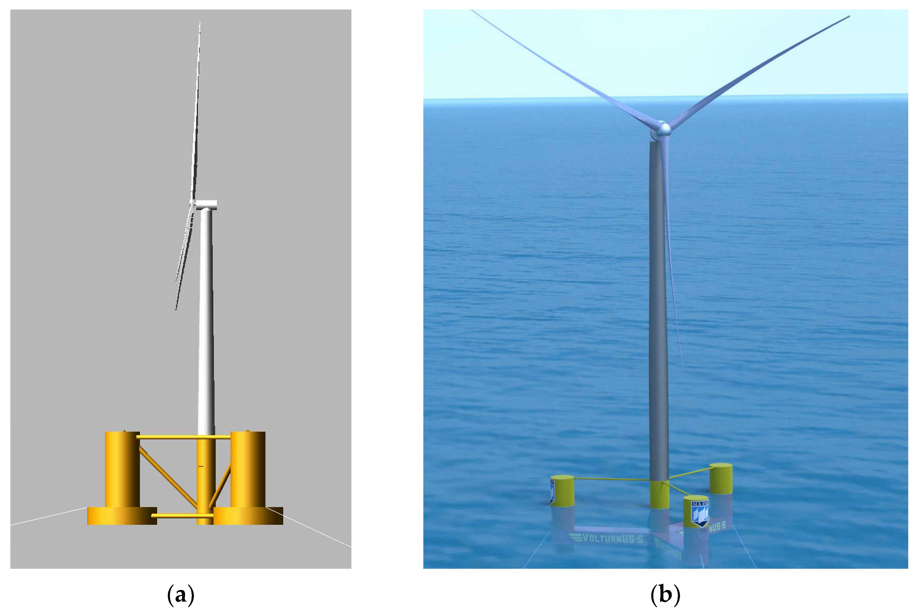
The reference semi-submersibles studied here are the aforementioned 5 MW OC4 and 15 MW UMaine designs, pictured in Figure 1. Both have a triangular configuration of three outer columns connected with braces and pontoons to a central column upon which the wind turbine is situated. While the 5 MW reference semi-submersible uses large lower columns for storing ballast and has diagonal braces connecting the columns, the 15 MW reference semi-submersible design instead has large rectangular pontoons and only a few braces connecting the outer columns to the main column. The relevant specifications of the reference semi-submersibles can be found in Table 3 in Section 3.2. In the present study, the 5 MW reference semi-submersible will be upscaled following logical processes and compared to the 15 MW reference semi-submersible.
2.3. Turbine Upscaling
The turbine upscaling methodology starts from the basis of linear upscaling methodology, wherein aerodynamic bending moments and masses scale cubically, and aerodynamic bending stresses are scale-invariant [7]. This methodology is then modified to apply scaling ratios more reflective of commercial data and reference wind turbines, meaning that technological improvement is indirectly assumed.
The turbine scale factor (st) is defined as the square root of the ratio of the power rating (P) between the original turbine and the upscaled turbine, as in Equation (1). The rotor radius (rrotor) is scaled with this scale factor as in Equation (2), resulting in a turbine swept area proportional to the power rating. The hub height (hhub) is then increased, as in Equation (3), such that the distance between the rotor and the still water level (air gap) is the same as in the original design.
st = (P/Po)1/2
rrotor = rrotor,ost
hhub = hhub,o − rrotor,o + rrotor
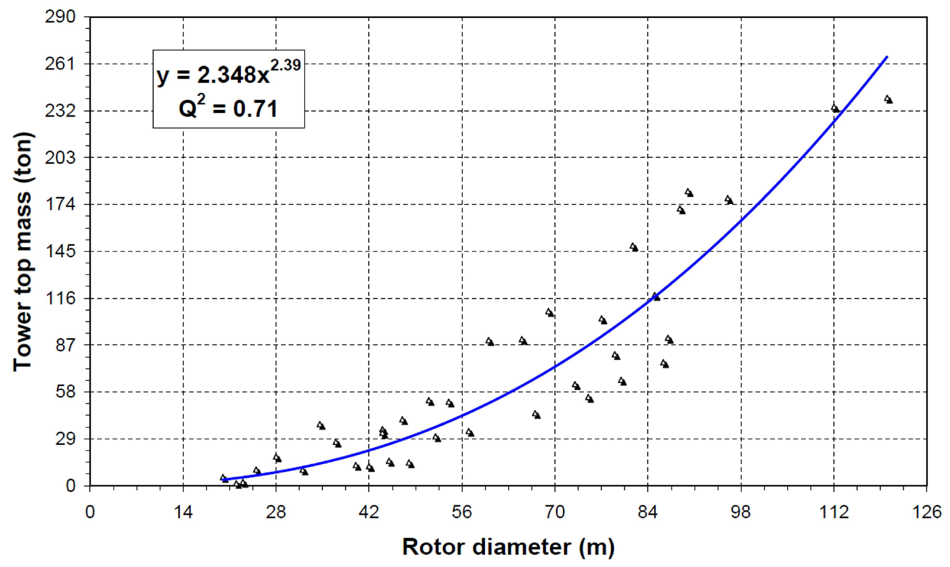
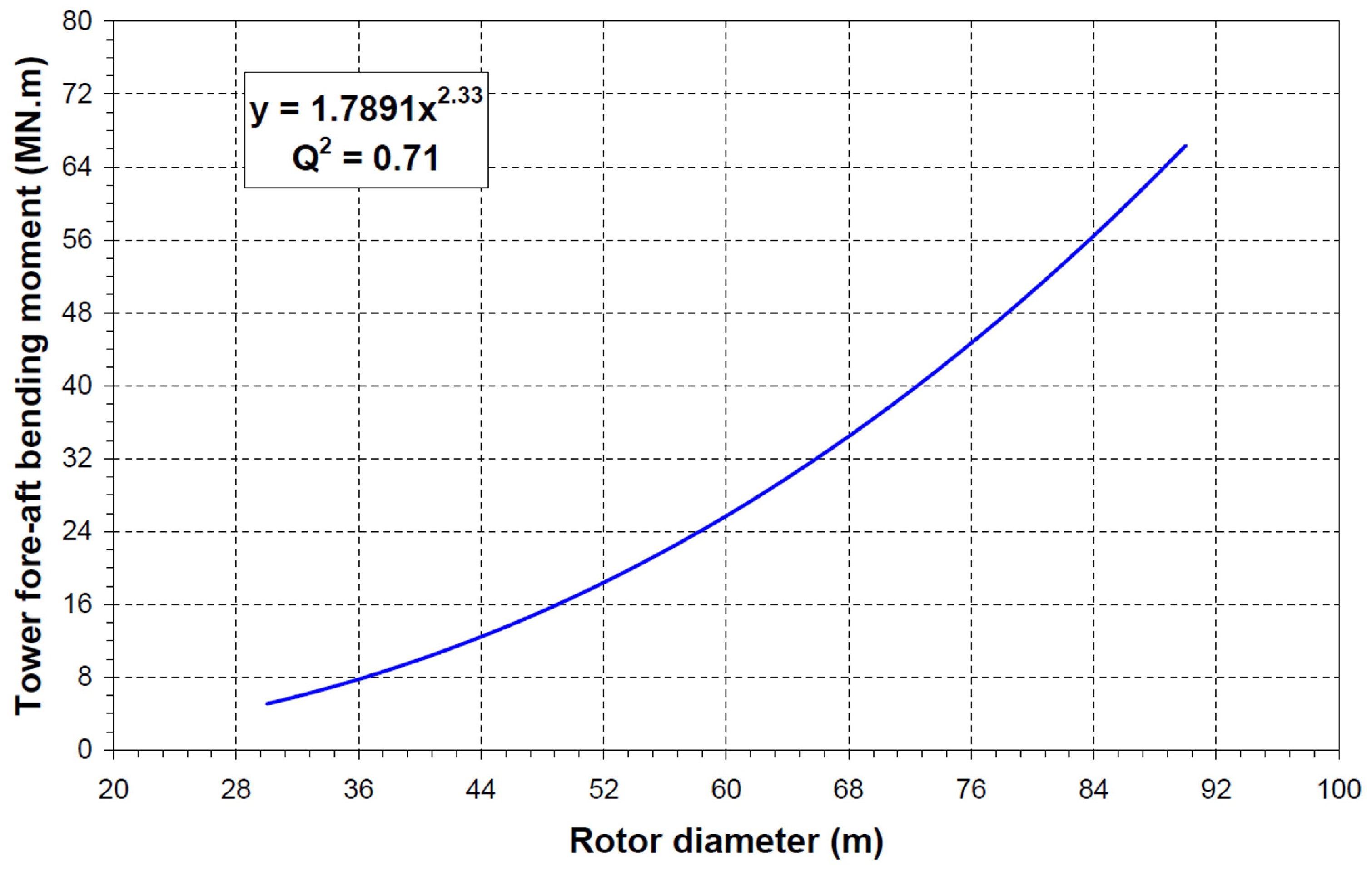
The blade mass (m) and hub mass are assumed to scale with the turbine scale factor to the power of 2.5, while the nacelle mass is assumed to scale with the turbine scale factor to the power of 2.3. The aerodynamic overturning moment (M) in the fore-aft direction experienced at the base is also assumed to scale to the power of 2.3, which seems reasonable considering that the aerodynamic loads are proportional to the blade-swept area with a little stronger wind velocity at higher altitude. These assumptions, shown in Equations (4)–(7), follow the scaling trends of commercial wind turbines, as shown in Figure 2 and Figure 3 [13,14], with a more conservative assumption for blade mass scaling in consideration of self-weight bending moments, which scale more quickly than aerodynamic bending moments due to being a product of blade mass and length, as opposed to blade area and length.
mblade = mblade,ost2.5
mhub = mhub,ost2.5
mnacelle = mnacelle,ost2.3
M = Most2.3
Next, let us consider tower scaling. Bending stress (σbending) is defined in Equation (8) and assumed to be constant as in linear upscaling laws, keeping allowable stress the same while upscaling the tower. For a finite element of constant radius and thickness representing a section of the tower, the distance to bending axis (y) scales with the tower radius, and the second moment of area (I) scales with the tower radius to the fourth power. This allows the tower radius scaling to be solved for as a function of the turbine scale factor, as in Equations (9) and (10), where sr is the scale factor for the tower radius.
σbending = My/I
My/I = Most2.3yosr/(Iosr4)
sr = st2.3/3
The upscaled tower mass can then be calculated from the radius scale factor (sr) and the upscaling ratio between tower lengths (ltower) as in Equation (11).
mtower = mtower,o(st2.3/3)2ltower/ltower,o
The resulting specifications for the upscaled wind turbines are listed in Table 2 in Section 3.1, including a comparison between the reference and presently upscaled tower diameter and thickness.
2.4. Semi-Submersible Upscaling
Following turbine upscaling, the upscaling of the floating substructure can subsequently be conducted. The upscaling method for the semi-submersible is based on the assumption made for scaling the overturning moment and involves scaling the pitch restoring stiffness proportionally to preserve the maximum static pitch angle. The static pitch restoring stiffness (C44) can be calculated from water density (ρ), moment of waterplane area (Iaw), submerged volume (∇), vertical center of buoyancy (zCB), and vertical center of gravity (zCG), as shown in Equation (12).
C44 = ρg(IAw + ∇(zCB − zCG))
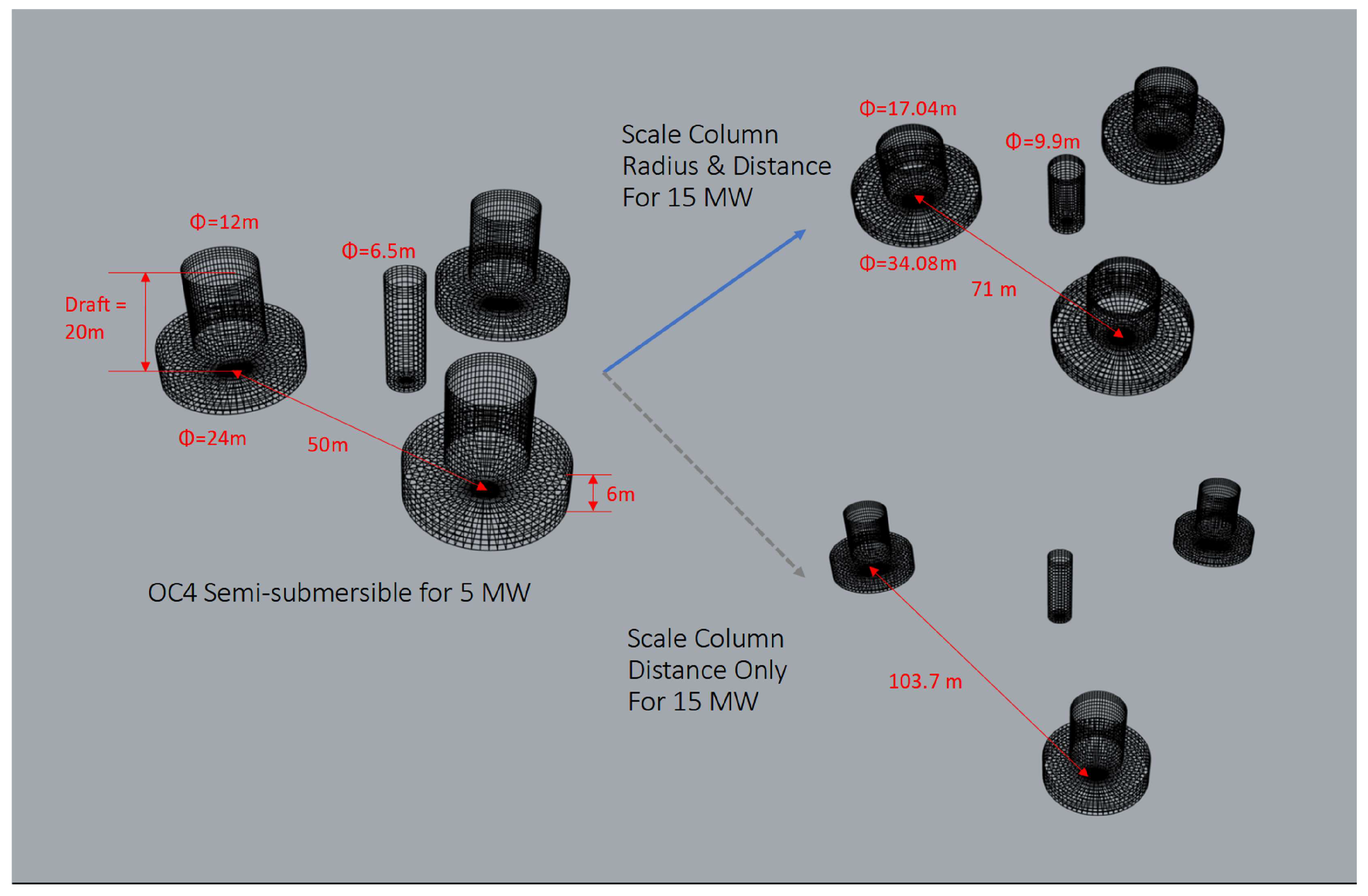
Because the moment of waterplane area can be increased by increasing either the column radius or the distance between columns, two different scaling approaches are developed for comparison: one that scales column radius and distance together with the same scale factor (referred to as Distance & Radius Scaling), and one that only scales the distance between columns (referred to as Distance Scaling). These two approaches are visualized with example meshes omitting the pontoons and braces in Figure 4, and they allow for comparison between the effects of scaling column radius and scaling column distance.
As an additional note, the mooring system is neglected for this kind of consideration, as a semi-taut or slack mooring system should not affect the static pitch angle, although an estimate for its mass is included in relevant calculations and represents approximately 2% of the total mass of the original 5 MW reference design.
In the original 5 MW reference design, the center of buoyancy and center of gravity are relatively close, and the pitch restoring stiffness closely scales with the waterplane area (IAw), which is proportional to column radius squared times the distance squared from the center. However, when upscaling the semi-submersible based on pitch restoring stiffness, the turbine mass scales more quickly than the semi-submersible mass, resulting in a higher center of gravity, while the center of buoyancy remains at the same height due to constant draft (assumed considering the limitation of quay-side assembly as in the survey of shipyards conducted by George [9]), making those terms non-negligible.
As the center of gravity term depends on the mass distribution, and the mass depends on the semi-submersible scaling, the scaling can be found using an iterative approach.
First, a guess is made for the semi-submersible scale factor (ss) which is then applied to the column radius (rcolumn) or distance (dcolumn), as in Equations (13) and (14). The radii of the braces (which have small mass relative to the total mass) are held constant while upscaling, and the center column is widened to fit the upscaled turbine tower if necessary.
rcolumn = rcolumn,oss
dcolumn = dcolumn,oss
From the upscaled dimensions, the submerged volume (∇) can then be calculated from the radius (r) and length (l) of each member as in Equation (15). This can be multiplied by the water density (ρ) to get the buoyancy (displaced water mass) and set equal to the total mass. The wall thickness (t) of the semi-submersible columns, braces, and pontoons are held constant, allowing for the metal mass (mmetal) to be calculated as in Equation (16), and ballast is then added until the total weight of the floating system equals the buoyant force, satisfying the static balance in heave as in Equation (17).
∇ = Σ(πr2lsubmerged)
mmetal = ρsteelΣ(2πrlt)
ρwater∇ = mturbine + mmetal + mballast + mmooring
The pitch restoring stiffness can then be calculated, and the process is repeated with a new guess for the semi-submersible scale factor until the stiffness matches the target stiffness.
In addition to the two upscaled semi-submersibles generated through the iterative static pitch angle approach, a third upscaled semi-submersible is generated simply by setting the column radius and distance equal to the UMaine design for comparison (referred to as Matching VolturnUS-S). The resulting specifications of all three upscaled semi-submersibles are shown in Table 3 in Section 3.2 alongside the specifications of the reference semi-submersibles.
The added mass (madded) and inertia (Iadded,pitch) in heave and pitch are approximated using coefficients and reference volumes listed in Appendix D of Det Norske Veritas’ Recommended Practice for Environmental Conditions and Loads [15]. These values are then summed with the mass (mtotal) and pitch moment of inertia (Ipitch), respectively, to estimate the natural period in heave (Theave) and pitch (Tpitch) for the floating wind turbine, as in Equations (18) and (19), and this approximation method was validated by estimating the natural periods of the reference wind turbines and comparing to the values listed in the definitions of the reference semi-submersibles and the work of Masciola [16], as shown in Table 1. Note that pitch natural period could not be estimated for the 15 MW reference semi-submersible because wall thicknesses were not specified, preventing calculation of the mass moment of inertia for individual pontoons and columns.
Theave = 2π[(mtotal + madded)/(ρwatergAw)]1/2
Tpitch = 2π[(Ipitch + Iadded,pitch)/(C44)]1/2
The stability is evaluated by calculating the distance between the center of buoyancy and metacenter (BM), as in Equation (20), then subtracting the center of gravity to find the metacentric height (GM), as in Equation (21).
BM = IAw/∇
GM = zCB + BM − zCG
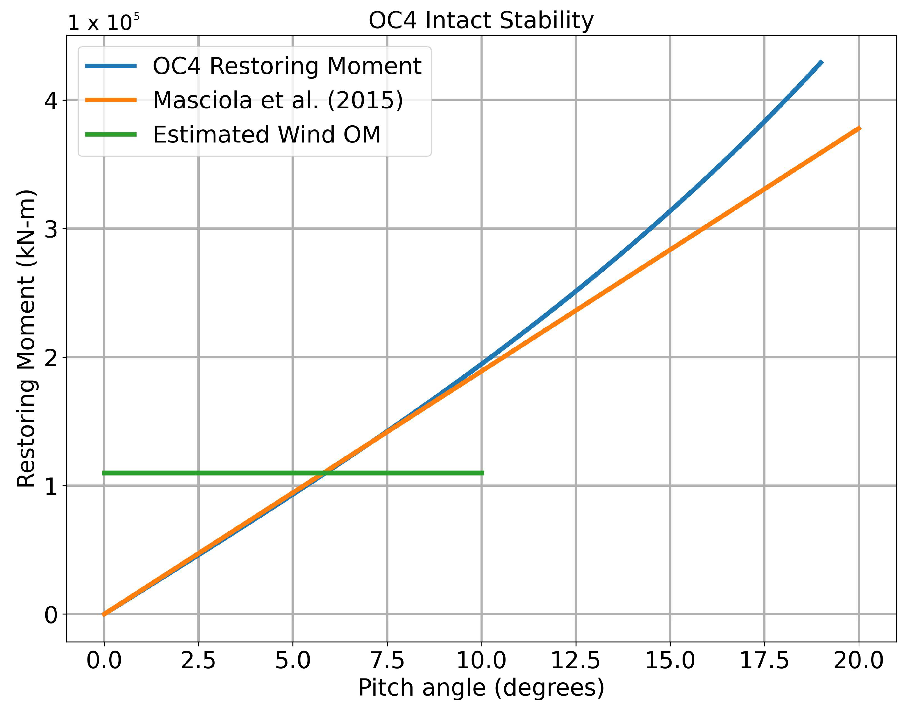
A curve of the intact stability can then be generated by multiplying the GM by the sine of the pitch angle as in Figure 5, where this approximation is also validated by comparison with the work of Masciola [16]. This curve is constrained by the requirement that the pitch angle is not large enough to fully submerge or elevate above water any upper columns of the semi-submersible. There is good agreement up to an angle of 10 degrees, which is the limit for continuing to operate the wind turbine.
2.5. Estimating Parameter Scaling with Pitch Restoring Stiffness
It is worth noting that the pitch restoring stiffness of the UMaine design is much lower than the value calculated from the assumption for overturning moment scaling. To facilitate the use of a different assumption for overturning moment scaling, a method to estimate how certain platform parameters scale is also proposed.
For example, metal mass scaling can be approximated as a function of column radius and distance scale factors sr and sd and the metal masses of the column caps, column walls, and braces and pontoons, as in Equation (22). Note that the third term in Equation (22) is a simplification, as a larger column radius also entails a shorter brace connecting the columns if the distance between column centers remains constant, which would be applicable if scaling only radius. Dividing both sides by the total metal mass and taking the logarithm results in Equation (23).
mmetalssN = mcapsr2 + mwallsr + mbracesd
Finally, by recognizing that the scale factors for column radius and column distance depend on the selected upscaling method, we can substitute the semi-submersible scale factor in for the column radius and distance scale factors. That is, when scaling only column distance, sd = ss, and sr = 1. When scaling both column distance and column radius with the same scale factor, sr = sd = ss. Then the equation can be approximated by setting ss equal to an assumed upper bound for the semi-submersible scale factor and substituting to solve for exponent N. This upper bound for ss should be chosen to be large enough to include the scale factor in the power function being considered but kept small to minimize error due to the power function approximation.
This process can similarly be repeated for the ballast mass as in Equations (24) and (25). The total mass is approximated as scaling with the column radius squared, as the displaced volume primarily scales with column radius due to the fixed draft assumption, and the mass of the turbine can be neglected.
mtotalsr2 = mballastssB + mmetalssN + mturbine
Pitch restoring stiffness (C44) scaling can then also be approximated as a function of column radius and distance scaling, though the equation is much more complex and should be solved numerically via Equations (26) and (27).
C44ssK = ρwaterg(IAwsr2sd2 + ∇sr2(zCB − zCG))
In Equation (27), the (zCB − zCG) term represents a reduction in the pitch restoring stiffness due to an elevated center of gravity. If the center of gravity were assumed to remain constant, the second term would become negligible, greatly simplifying the equation to Equation (28) and obviating the need for iteration with Equation (26). The pitch restoring stiffness would simply scale with the radius and column scale factors.
ssK = sr2sd2
To estimate the parameter scaling as a function of pitch restoring stiffness, the scaling exponent of the relevant parameter can be divided by the scaling exponent for pitch restoring stiffness. The parameter scaling as a function of the turbine scale factor can then be estimated by multiplying by the overturning moment scaling exponent assumed, 2.3. The results of this estimation process are listed in Table 4 in Section 3.4.
3. Results and Discussion
3.1. Comparison between Reference and Upscaled Wind Turbines
When determining the blade diameter for the same rated power, the rated wind velocity at the given site is an important factor. Therefore, it has to be considered when upscaling a turbine from one site to another site. However, in this paper, we did not consider that factor, assuming that wind conditions are similar among the considered FOWTs. Small changes in the Reynolds number with the scaling of the blade are also neglected.
As shown in Table 2, the rotor radius and hub height of the upscaled designs underpredict the reference designs by approximately 10%. A higher tip speed for the same generator RPM implies a larger rotor radius; this is likely due in part to the higher tip speeds of the reference turbines, which have been neglected in the upscaling process. While the 5 MW reference wind turbine that is being upscaled was originally designed for onshore applications and, thus, has a tip speed constraint to reduce noise, the 10 MW and 15 MW reference wind turbines were designed for offshore applications, where noise is less of an issue. Higher tip speed ratios also result in a more slender blade, as the optimum chord length varies inversely with the tip speed ratio squared [17] (p. 68), although real blades must make adjustments and approximations for structural and manufacturing considerations, which were neglected here.
Even with the less than linear mass scaling assumptions, the masses of the upscaled designs remain conservative compared to those of the reference designs. At 10 MW, the upscaled hub mass is around 65% greater than that of the reference design, while at 15 MW, the upscaled nacelle mass is around 34% greater than that of the reference. This is in part because the generator mass of the 15 MW reference design is almost the same as that of the 10 MW reference design, at 371.6 tonnes and 357.3 tonnes, respectively. Both generators were designed using the same design tool, GeneratorSE, later renamed DrivetrainSE, but the 15 MW design makes a more aggressive assumption that a thermal management system will be in place to limit temperatures produced by the generator, allowing for higher current loading and an increase in power output without a corresponding increase in mass [2]. Since no further explanation was given for this assumption, it is not included in the upscaling procedure.
Each reference turbine tower has a different shape, and, thus, a comparison can only be made roughly, but there appears to be agreement within 10% between the reference and upscaled towers for most parameters. The base diameter, base thickness, and top diameter appear to be consistently underestimated by about 10%, while the top thickness appears to be overestimated by about 20%, which may also depend on the quality of steel used. Overall, however, the turbine mass scaling is reasonable enough to be used in the next step, semi-submersible upscaling.
3.2. Semi-Submersible Upscaling Trends
Comparing the metal mass of the Distance & Radius Scaling, Distance Scaling, and OC4 columns of Table 3, it is apparent that the metal mass of the platform increases primarily with column radius scaling. This is because the columns account for most of the platform’s metal mass. Column radius scaling also increases the displaced volume, in turn increasing the ballast mass necessary to satisfy the static balance in heave. For both column radius and distance scaling, the platform’s total mass scales more slowly than that of the wind turbine, resulting in elevation of the floating system’s center of gravity, as well as its metacenter, as the GM of the system increases with the second moment of waterplane area. Scaling column radius causes both the center of gravity and metacenter to elevate more slowly due to the increased platform metal and ballast mass and displaced volume.
The heave natural period of the platform also increases with column radius scaling. This is because the heave added mass is assumed to reflect a hemispherical reference volume, or the cube of column radius, while the hydrostatic stiffness in heave scales with waterplane area, or column radius squared. The heave natural period appears to decrease slightly when scaling only column distance because the central column radius is increased to match the radius of the turbine tower base. This may increase the resonant response of the structure during storm conditions with long wave periods.
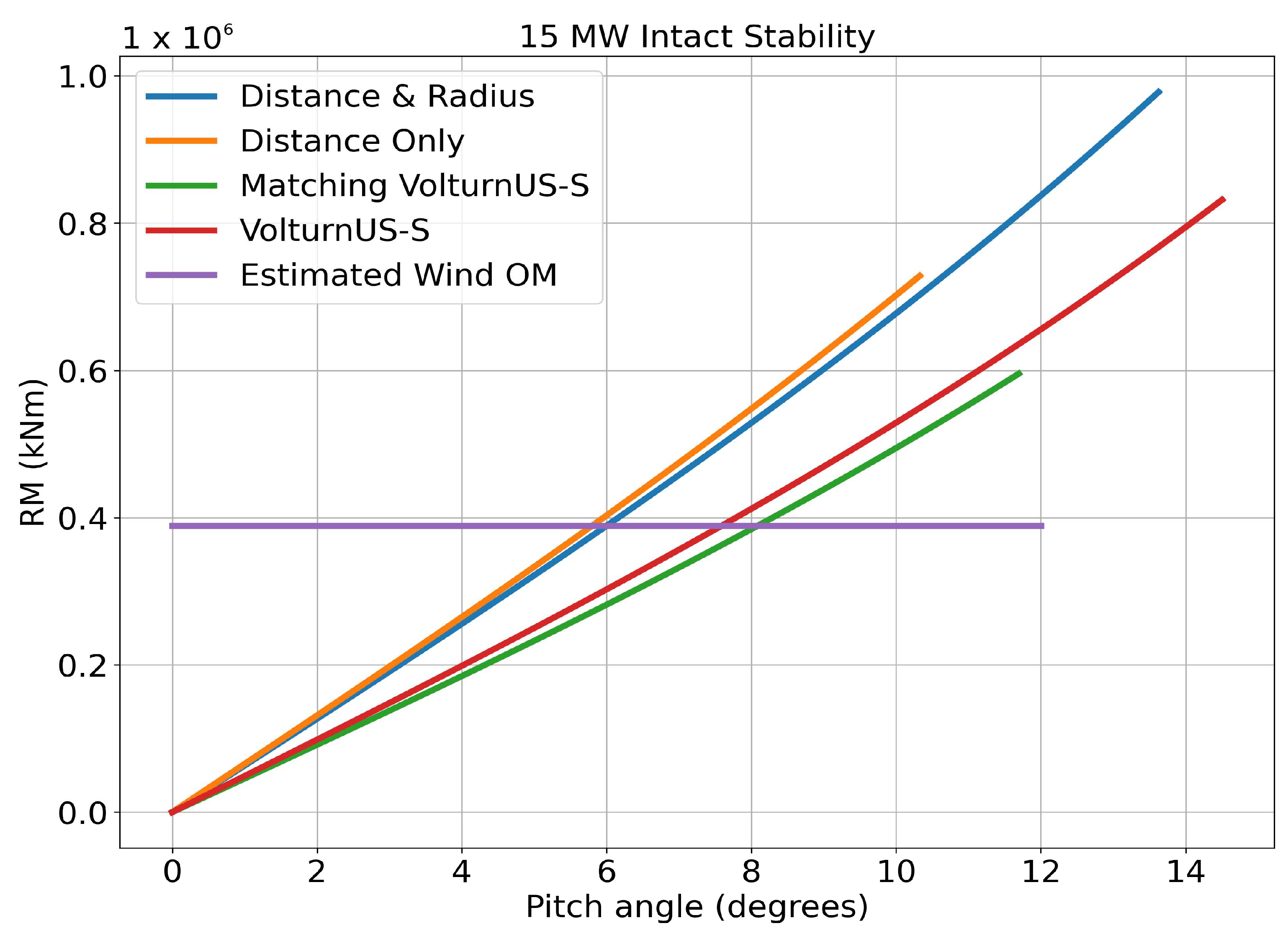
From the intact stability curves shown in Figure 6, the main difference between Distance & Radius scaling and Distance Only scaling is that the curve for scaling only column distance is shorter due to a lower pitch angle required to submerge or elevate an upper column. This similarity is to be expected, as both upscaling approaches target the same pitch restoring stiffness. It can also be seen that the stability curve differs for the UMaine VolturnUS-S design due to its differing pitch restoring stiffness.
Scaling in column distance only for the OC4-type semi-submersible is likely to pose a significant challenge in designing connecting braces, as they have to bear significantly increased bending moments due to their increased lengths. Radius–distance scaling also has the advantage that the heave and pitch natural periods are farther away from the peak period of 50-year design storms than distance-only scaling. In this regard, the radius–distance scaling seems more reasonable than distance-only scaling if an OC4-type semi-semisubmersible is to be designed.
3.3. Comparison with UMaine Design
By setting the column distance and column radius equal to that of the 15 MW reference design rather than using the overturning moment assumption to predict a scale factor, a comparison was made between the two designs, listed as Matching VolturnUS-S and UMaine VolturnUS-S in Table 3, respectively.
The main differences between the OC4 design and the UMaine design are the latter’s use of large rectangular pontoons connecting the lower parts of the columns. These serve to replace the large lower columns and many of the braces found in the OC4 design, which accounts for approximately 400 tonnes of the metal mass saved. Additionally, the large rectangular pontoons of the UMaine design displace about 3000 more cubic meters of water than the large lower columns of the OC4 design, increasing the ballast mass and, thus, lowering the center of gravity. However, the GM is approximately the same between the two designs, as the increase in displaced volume also decreases the BM.
The large rectangular pontoons also act as heave plates, increasing the heave added mass by about 8000 tonnes. The pontoons also enable the UMaine design to use relatively smaller columns (and, thus, smaller waterplane area). Both of the above factors contributed to increase the heave natural period to 20.4 s, which is beneficial as being farther away from typical storms’ peak period. In view of this observation, modifying the 15 MW OC4-semi design to have flatter column-bottom-connecting pontoons may help to remove most bracings and solid ballasts while contributing to better heave and pitch natural periods.
3.4. Parameter Scaling Estimation
The results of the parameter scaling estimation process (Estimated) are listed in Table 4 alongside the exponents for a Microsoft Excel power regression trendline (Regression) using the upscaled semi-submersible values, for comparison. An estimate is also made for the case of scaling column radius only, though this would run into the issue of lower column diameter exceeding the distance between columns in actuality. There is good agreement between the estimated and regression values for Distance & Radius Scaling, for which the estimated values are consistently slightly more conservative. Meanwhile, there is less agreement for the Distance Scaling, the resulting error would still be minimal due to the fact that distance scaling does not significantly increase the platform’s metal mass to begin with. Therefore, this method can be used to estimate the metal mass scaling for varying proportions of column distance and column radius scaling, as well as varying pitch restoring stiffness targets.
As shown in Table 4, neglecting the (zCB − zCG) term in Equation (27), results in consistent underprediction of the metal mass needed. This is because the higher center of gravity reduces the pitch restoring stiffness, which must then be overcome by increasing the semi-submersible scale factor and, thus, increasing the metal mass. As such, while more complex, the present methodology of taking the center of gravity into account is more accurate when attempting to minimize the platform metal mass.
Additionally, the third section of Table 4 shows that, for the given assumptions, metal mass will always scale less quickly than the turbine power rating, which has an exponent of 2 by definition, implying a favorable reduction in the proportion of cost accounted for by metal mass as floating wind turbines scale. It is important to note, however, that scaling column distance only with the proposed method does not consider the feasibility of actual construction, and it should be considered a tool for mapping out the potential design space when upscaling until a structural analysis is performed.
4. Conclusions and Future Work
A generic method for upscaling a semi-submersible-type floating offshore wind turbine has been presented, with two variations that highlight the different effects of scaling the semi-submersible’s column radius and column distance. This upscaling was done in the range of 5 MW to 15 MW, as reference semi-submersible designs are available for reference wind turbines at those power ratings, and because the scaling of the floating substructure represents an important area of potential cost savings as new wind turbines are being developed and reaching the 15 MW mark.
Turbine upscaling using mass and overturning moment exponents less than cubic was shown to have good agreement with the reference 10 MW and 15 MW wind turbines, with an exception for nacelle mass at 15 MW that is explained by assumptions for a more advanced generator cooling system in the reference design. Additionally, the upscaled rotor radius is observed to undershoot the reference designs by approximately 10% due to the effect of tip speed ratio, which was neglected in this upscaling process. Detailed design of the blade shape should be considered in future work as higher tip speed ratios result in more slender, flexible blades, which then require materials with more stiffness to prevent issues with tower clearance.
The semi-submersible was upscaled using the same acceptable-mean-pitch-angle assumption made for turbine upscaling, increasing the pitch restoring stiffness proportionally to warrant an acceptable static pitch angle. The center of gravity was found to rise when upscaling with this method because the turbine mass scales more quickly than that of the semi-submersible, though accompanied by a corresponding increase in GM. Scaling column radius was found to increase the metal mass and ballast mass of the platform, slowing the elevation of the center of gravity, and raising the heave natural period. Scaling column distance only was found to slightly reduce the heave natural period, which may pose issues related to resonant effects during storm conditions with long wave periods.
The reference semi-submersible design developed by UMaine addressed the issues caused by scaling column distance through the use of large rectangular pontoons. These pontoons increase the displaced volume compared to the analogous large lower columns of the OC4 reference design, thus, increasing the ballast mass necessary and lowering the hull center of gravity. Additionally, the pontoons serve as large heave plates that increase the heave added mass and raise the heave natural period.
As the reference semi-submersible design has a lower pitch restoring stiffness than that predicted by the overturning moment assumption, a method to estimate how platform parameters scale with respect to pitch restoring stiffness was presented. This method is found to have reasonable agreement with a power regression of the upscaled semi-submersible specifics, and may be useful for initial estimates when upscaling a semi-submersible with static balance in pitch. Additionally, the platform metal mass scaling is found to be favorable, increasing more slowly than the power rating of the turbine for any combination of column radius and column distance scaling with the given assumptions; in other words, requiring less metal mass per power as the turbine scales.
The presented method to quickly scale up a FOWT considers primarily mass scaling and static force balances, neglecting more detailed design considerations. After this, more optimization needs to be conducted through design spirals. As one of the assumptions was holding metal wall thickness constant while upscaling the semi-submersible, a good area for further investigation would be structural analysis of the upscaled designs. This would also be well-complemented by scaling the mooring system, which was not changed when upscaling, and simulations to analyze the dynamic loading and response [18,19,20,21], as well as a more in-depth analysis of how tip speed ratios are affected by upscaling, and how this impacts the wind turbine blades. Applying the upscaling method to different designs, such as concrete hulls, may also result in different upscaling trends. Finally, analysis of cost scaling using the upscaled specifications would be a natural continuation, as reducing the cost of floating wind is one of the motivations for this research.
Author Contributions
Conceptualization, J.W. and M.-H.K.; methodology, J.W.; software, J.W.; validation, J.W. and M.-H.K.; formal analysis, J.W. and M.-H.K.; investigation, J.W.; writing—original draft preparation, J.W.; writing—review and editing, J.W. and M.-H.K.; visualization, J.W.; supervision, M.-H.K.; funding acquisition, M.-H.K. All authors have read and agreed to the published version of the manuscript.
Funding
This research received no external funding.
Institutional Review Board Statement
Not applicable.
Informed Consent Statement
Not applicable.
Data Availability Statement
Data contained within article.
Conflicts of Interest
The authors declare no conflict of interest.
References
- Jonkman, J.; Butterfield, S.; Musial, W.; Scott, G. Definition of a 5-MW Reference Wind Turbine for Offshore System Development; National Renewable Energy Laboratory: Golden, CO, USA, 2009. [Google Scholar]
- Gaertner, E.; Rinker, J.; Sethuraman, L.; Zahle, F.; Anderson, B.; Barter, G.; Abbas, N.; Meng, F.; Bortolotti, P.; Skrzypinski, W.; et al. Definition of the IEA 15-Megawatt Offshore Reference Wind Turbine; National Renewable Energy Laboratory: Golden, CO, USA, 2020. [Google Scholar]
- Robertson, A.; Jonkman, J.; Masciola, M.; Song, H.; Goupee, A.; Coulling, A.; Luan, C. Definition of the Semisubmersible Floating System for Phase II of OC4; National Renewable Energy Laboratory: Golden, CO, USA, 2014. [Google Scholar]
- Allen, C.; Viselli, A.; Dagher, H.; Goupee, A.; Gaertner, E.; Abbas, N.; Hall, M.; Barter, G. Definition of the UMaine Volturn US-S Reference Platform Developed for the IEA Wind 15-Megawatt Offshore Reference Wind Turbine; National Renewable Energy Laboratory: Golden, CO, USA, 2020. [Google Scholar]
- Musial, W.M.; Bourgeois, R.; Norton, G.; Derby, M.; Reeve, E.; Peterson, K.; Bauman, I.; Matthiesen, J.; Burke, O. Research and Development Roadmap Version 2.0; National Offshore Wind Research & Development Consortium: Stony Brook, NY, USA, 2019. [Google Scholar]
- NOWRDC. Innovation in Offshore Wind Solicitation 1.0; National Offshore Wind Research & Development Consortium: Stony Brook, NY, USA, 2020. [Google Scholar]
- Sieros, G.; Chaviaropoulos, P.; Sørensen, J.D.; Bulder, B.H.; Jamieson, P. Upscaling Wind Turbines: Theoretical and practical aspects and their impact on the cost of energy. Wind Energy 2012, 15, 3–17. [Google Scholar] [CrossRef] [Green Version]
- Leimeister, M.; Bachynski, E.; Muskulus, M.; Thomas, P. Rational upscaling of a semi-submersible floating platform supporting a wind turbine. In Energy Procedia, Proceedings of the 13th Deep Sea Offshore Wind R&D Conference, EERA DeepWind’2016, Trondheim, Norway, 20–22 January 2016; Tande, J.O.G., Kvamsdal, T., Muskulus, M., Eds.; Elsevier: Amsterdam, The Netherlands, 2016; pp. 434–442. [Google Scholar]
- George, J. WindFloat Design for Different Turbine Sizes. Master’s Thesis, Instituto Superior Técnico, Lisbon, Portugal, 2014. [Google Scholar]
- Kikuchi, Y.; Ishihara, T. Upscaling and levelized cost of energy for offshore wind turbines supported by semi-submersible floating platforms. In Journal of Physics: Conference Series, Proceedings of the 16th Deep Sea Offshore Wind R&D Conference, EERA DeepWind’2019, Trondheim, Norway, 16–18 January 2019; IOP Publishing Ltd.: Bristol, UK, 2019; p. 012033. [Google Scholar]
- Bortolotti, P.; Tarres, H.; Dykes, K.; Merz, K.; Sethuraman, L.; Verelst, D.; Zahle, F. IEA Wind Task 37 on Systems Engineering in Wind Energy WP2.1 Reference Wind Turbines; National Renewable Energy Laboratory: Golden, CO, USA, 2019. [Google Scholar]
- Bak, C.; Zahle, F.; Bitsche, R.; Kim, T.; Yde, A.; Henriksen, L.C.; Natarajan, A.; Hansen, M.H. Description of the DTU 10 MW Reference Wind Turbine; DTU Wind Energy Report-I-0092 5; DTU Wind Energy: Roskilde, Denmark, 2013. [Google Scholar]
- Jamieson, P. Loading and Cost Trends Using Certification Calculation; Internal Report; UPWIND: Roskilde, Denmark, 2007. [Google Scholar]
- Ashuri, T. Beyond Classical Upscaling: Integrated Aeroservoelastic Design and Optimization of Large Offshore Wind Turbines. Ph.D. Thesis, Sharif University of Technology, Tehran, Iran, 2012. [Google Scholar]
- Det Norske Veritas. Recommended Practice DNV-RP-C205: Environmental Conditions and Environmental Loads; Det Norske Veritas: Bærum, Norway, 2010; pp. 174–177. [Google Scholar]
- Masciola, M.; Chen, X.; Yu, Q. Evaluation of the Dynamic-Response-Based Intact Stability Criterion for Floating Wind Turbines. In Proceedings of the ASME 2015 34th International Conference on Ocean, Offshore and Arctic Engineering. Volume 9: Ocean Renewable Energy, St. John’s, NL, Canada, 31 May–5 June 2015; ASME: New York, NY, USA, 2015. [Google Scholar]
- Anderson, C. Wind Turbines: Theory and Practice, 1st ed.; Cambridge University Press: Cambridge, UK, 2020; pp. 64–79. [Google Scholar]
- Jang, H.K.; Park, S.; Kim, M.H.; Kim, K.H.; Hong, K. Effects of heave plates on the global performance of a MUFOWT. Renew. Energy 2019, 134, 526–537. [Google Scholar] [CrossRef]
- Kim, H.C.; Kim, M.H. Global Performances of a Semi-Submersible 5 mw Wind-Turbine Including Second-Order Wave-Diffraction Effects. Ocean Syst. Eng. 2015, 5, 139–160. [Google Scholar] [CrossRef]
- Kim, H.C.; Kim, M.H. Comparison of Simulated Platform Dynamics in Steady/Dynamic Winds and Irregular Waves for OC4 Semi-Submersible 5 mw Wind-Turbine against Deepcwind Model-Test Results. Ocean Syst. Eng. 2016, 6, 1–21. [Google Scholar] [CrossRef]
- Bae, Y.H.; Kim, M.H. Coupled dynamic analysis of multiple wind turbines on a large floater. Ocean Eng. 2014, 92, 175–187. [Google Scholar] [CrossRef]
Figure 1.
(a) OC4 DeepCWind Semi-submersible for NREL 5 MW Wind Turbine, reprinted from [3]; and (b) UMaine VolturnUS-S Semi-submersible for NREL 15 MW Reference Wind Turbine, reprinted from [4].

Figure 2.
Tower Top Mass as a Function of Rotor Diameter, Commercial Data, and Trendline (reprinted from [14], reprint from [13]).

Figure 3.
Tower Fore-Aft Bending Moment as a Function of Rotor Diameter, Commercial Data, and Trendline (reprinted from [14], reprint from [13]).

Figure 4.
Example Mesh of OC4 Semi-submersible; 15 MW Semi-submersible, upscaled in distance and radius; and 15 MW Semi-submersible, upscaled in distance only.
Figure 4.
Example Mesh of OC4 Semi-submersible; 15 MW Semi-submersible, upscaled in distance and radius; and 15 MW Semi-submersible, upscaled in distance only.

Figure 5.
OC4 Floater Intact Stability Curve. Additional data adapted from [16].
Figure 5.
OC4 Floater Intact Stability Curve. Additional data adapted from [16].

Figure 6.
Intact Stability Curves for 15 MW Floating Offshore Wind Turbines.


| Unit | 5 MW | 15 MW | |
|---|---|---|---|
| Heave Natural Period | |||
| Estimated | [s] | 16.5 | 19.1 |
| Simulated | [s] | 17.2 1 | 20.4 2 |
| Pitch Natural Period | |||
| Estimated | [s] | 26.4 | - |
| Simulated | [s] | 27.1 1 | 27.8 2 |
Table 2.
Reference and upscaled wind turbines.
| Units | NREL 5 MW | Scaled 10 MW | IEA 10 MW | Scaled 15 MW | IEA 15 MW | |
|---|---|---|---|---|---|---|
| Power Rating | 5.0 | 10 | 10.0 | 15 | 15.0 | |
| Turbine Scale Factor | 1.00 | 1.41 | - | 1.73 | - | |
| Rotor Radius | m | 63.0 | 89.10 | 99.0 | 109.12 | 120.0 |
| Blade Length | m | 61.5 | 87.0 | 96.7 | 106.5 | 116.0 |
| Hub Radius | m | 1.5 | 2.12 | 2.3 | 2.60 | 4.0 |
| Hub Height | m | 90.0 | 116.10 | 119.0 | 136.12 | 150.0 |
| Tip Speed | m/s | 80.0 | 80 | 90.0 | 80 | 95.0 |
| Tower Length | m | 77.6 | 103.70 | 115.6 | 123.72 | 144.6 |
| Tower Base Diameter | m | 6.5 | 8.48 | 9.0 | 9.90 | 10.0 |
| Tower Base Thickness | mm | 27.0 | 35.2 | 38.0 | 41.1 | 45.5 |
| Tower Top Diameter | m | 3.9 | 5.05 | 5.5 | 5.90 | 6.5 |
| Tower Top Thickness | mm | 19.0 | 24.8 | 20.0 | 29.0 | 24.0 |
| Blade Mass | t | 17.7 | 42.2 | 47.7 | 70.0 | 65.3 |
| Hub Mass | t | 56.8 | 135.0 | 81.7 | 224.2 | 190.0 |
| Nacelle Mass | t | 240 | 530 | 540 | 850 | 630 |
| Tower Mass | t | 250 | 570 | 630 | 920 | 860 |
| Total Mass | t | 600 | 1360 | 1400 | 2200 | 1880 |
Table 3.
Reference and upscaled semi-submersibles.
| 5 MW | 10 MW | 15 MW | ||||||
|---|---|---|---|---|---|---|---|---|
| OC4 | Distance & Radius Scaling | Distance Scaling | Distance & Radius Scaling | Distance Scaling | Matching VolturnUS-S | UMaine VolturnUS-S | ||
| Turbine Scale Factor | - | 1.41 | 1.41 | 1.73 | 1.73 | 1.73 | - | |
| Platform Scale Factor | - | 1.24 | 1.57 | 1.42 | 2.07 | - | - | |
| Outer Column Distance | m | 50 | 62.05 | 78.7 | 71 | 103.7 | 89.6 | 89.6 |
| Outer Column Radius | m | 6 | 7.45 | 6.00 | 8.52 | 6.00 | 6.25 | 6.25 |
| RNA Mass | t | 350 | 790 | 790 | 1280 | 1280 | 1280 | 990 |
| RNA zCG | m | 90.0 | 113.7 | 113.7 | 133.7 | 133.7 | 133.7 | 150.0 |
| Tower Mass | t | 250 | 570 | 570 | 920 | 920 | 920 | 1260 |
| Tower zCG | m | 43.4 | 54.6 | 54.6 | 63.3 | 63.3 | 63.3 | 56.5 |
| Turbine Mass | t | 600 | 1360 | 1360 | 2200 | 2200 | 2200 | 2250 |
| Metal Mass | t | 3850 | 5250 | 4140 | 6370 | 4360 | 4450 | 4010 |
| Ballast Mass | t | 9620 | 15,070 | 9290 | 19,870 | 8930 | 9780 | 13,840 |
| Platform Mass | t | 13,470 | 20,320 | 13,430 | 26,240 | 13,290 | 14,240 | 17,840 |
| Platform zCG | m | −13.46 | −13.79 | −13.56 | −13.91 | −13.55 | −13.69 | −14.94 |
| Platform zCB | m | −13.15 | −13.16 | −13.13 | −13.15 | −13.09 | −13.08 | −13.63 |
| Total Mass | t | 14,340 | 21,950 | 15,060 | 28,720 | 15,770 | 16,720 | 20,090 |
| Total zCG | m | −9.89 | −7.49 | −4.40 | −4.89 | 2.83 | 1.77 | −2.32 1 |
| GM | m | 7.45 | 10.37 | 15.43 | 12.75 | 24.05 | 15.73 | 15.6 1 |
| Heave Natural Period | s | 17.2 | 17.3 | 16.3 | 17.9 | 16.2 | 16.3 | 20.4 |
| Pitch Natural Period | s | 27.1 | 27.4 | 24.2 | 28.3 | 23.6 | 26.4 | 27.8 |
| Heave Restoring Stiffness | N/m | 3.82 × 10⁶ | 5.91 × 10⁶ | 4.08 × 10⁶ | 7.74 × 10⁶ | 4.32 × 10⁶ | 4.59 × 10⁶ | 4.49 × 10⁶ 1 |
| Pitch Restoring Stiffness | Nm/rad | 1.05 × 10⁹ | 2.23 × 10⁹ | 2.28 × 10⁹ | 3.59 × 10⁹ | 3.72 × 10⁹ | 2.58 × 10⁹ | 2.65 × 10⁹ 1 |
| Max Static Pitch Angle | deg | 6.00 | 6.26 | 6.14 | 6.21 | 5.99 | 8.64 | 8.41 1 |
1 Estimated with present study methodology.
Table 4.
Metal mass scaling exponents.
| Distance Scaling | Distance & Radius Scaling | Radius Scaling | |
|---|---|---|---|
| As function of semi-submersible scale factor | |||
| Estimated | 0.119 | 1.515 | 1.490 |
| Regression | 0.158 | 1.413 | - |
| As function of pitch restoring stiffness | |||
| Estimated | 0.065 | 0.424 | 0.784 |
| Neglecting zCB − zCG | 0.059 | 0.372 | 0.745 |
| Regression | 0.092 | 0.404 | - |
| As function of turbine scale factor | |||
| Estimated | 0.150 | 0.975 | 1.803 |
| Neglecting zCB − zCG | 0.136 | 0.856 | 1.714 |
| Regression | 0.212 | 0.929 | - |
Publisher’s Note: MDPI stays neutral with regard to jurisdictional claims in published maps and institutional affiliations. |
© 2021 by the authors. Licensee MDPI, Basel, Switzerland. This article is an open access article distributed under the terms and conditions of the Creative Commons Attribution (CC BY) license (https://creativecommons.org/licenses/by/4.0/).
Share and Cite
MDPI and ACS Style
Wu, J.; Kim, M.-H. Generic Upscaling Methodology of a Floating Offshore Wind Turbine. Energies 2021, 14, 8490. https://0-doi-org.brum.beds.ac.uk/10.3390/en14248490
AMA Style
Wu J, Kim M-H. Generic Upscaling Methodology of a Floating Offshore Wind Turbine. Energies. 2021; 14(24):8490. https://0-doi-org.brum.beds.ac.uk/10.3390/en14248490
Chicago/Turabian StyleWu, Jeffrey, and Moo-Hyun Kim. 2021. "Generic Upscaling Methodology of a Floating Offshore Wind Turbine" Energies 14, no. 24: 8490. https://0-doi-org.brum.beds.ac.uk/10.3390/en14248490
Note that from the first issue of 2016, this journal uses article numbers instead of page numbers. See further details here.