Article

Preferential Protection of Low Coordinated Sites in Pt Nanoparticles for Enhancing Durability of Pt/C Catalyst

1
Department of Chemical & Biomolecular Engineering, Korea Advanced Institute of Science and Technology (KAIST), 291, Daehak-ro, Yuseong-gu, Daejeon 34141, Korea
2
R&D Division, KOLON Industries Inc., 110, Magokdong-ro, Seoul 07793, Korea
3
Advanced Battery Center, KAIST Institute for the NanoCentury, Korea Advanced Institute of Science and Technology (KAIST), 291, Daehak-ro, Yuseong-gu, Daejeon 34141, Korea
*
Authors to whom correspondence should be addressed.
Submission received: 4 February 2021 / Revised: 23 February 2021 / Accepted: 24 February 2021 / Published: 4 March 2021
(This article belongs to the Special Issue Polymer Electrolyte Membrane Fuel Cells and Electrolyzers)

Abstract

:
Protecting low coordinated sites (LCS) of Pt nanoparticles, which are vulnerable to dissolution, may be an ideal solution for enhancing the durability of polymer electrolyte fuel cells (PEMFCs). However, the selective protection of LCSs without deactivating the other sites presents a key challenge. Herein, we report the preferential protection of LCSs with a thiol derivative having a silane functional group, (3-mercaptopropyl) triethoxysilane (MPTES). MPTES preferentially adsorbs on the LCSs and is converted to a silica framework, providing robust masking of the LCSs. With the preferential protection, the initial oxygen reduction reaction (ORR) activity is marginally reduced by 8% in spite of the initial electrochemical surface area (ECSA) loss of 30%. The protected Pt/C catalyst shows an ECSA loss of 5.6% and an ORR half-wave potential loss of 5 mV after 30,000 voltage cycles between 0.6 and 1.0 V, corresponding to a 6.7- and 2.6-fold durability improvement compared to unprotected Pt/C, respectively. The preferential protection of the vulnerable LCSs provides a practical solution for PEMFC stability due to its simplicity and high efficacy.

1. Introduction

Polymer electrolyte membrane fuel cells (PEMFCs) have been used in automobile and stationary applications due to their advantages of high efficiency, zero emissions, and moderate operation conditions [1,2]. In current PEMFCs, platinum nanoparticles (NPs) supported on carbon materials (Pt/C) are commonly used as an oxygen reduction reaction (ORR) catalyst for the cathode due to their high catalytic activity. However, under normal PEMFC operation conditions, Pt NPs are gradually degraded, resulting in a loss in electrochemical surface area (ECSA) and ORR activity. Coalescence, dissolution, and detachment from the carbon support of Pt NPs have been reported as the main degradation mechanisms [3,4,5,6].
Pt dissolution occurs due to the intrinsic electrochemical and chemical instability of Pt NP surfaces under potential drift, and the highly acidic conditions of the PEMFC (Figure 1a). According to the phase–pH diagram of Pt NPs, Pt oxide (PtOx) is spontaneously formed at higher potentials, triggering Pt dissolution [7,8,9]. In the oxide formation process, place-exchange of Pt and oxygen leads to exposure of the Pt atom of PtOx to the surface, which is prone to Pt dissolution due to its high surface energy. The surface site, having high surface energy, has a low coordination number of the adjacent Pt atoms; thus, it tends to bind with oxygen intermediates to stabilize its surface energy. At lower potentials, the oxides are reduced with the removal of oxygen atoms, generating defects with a low coordination number. The defects are subject to oxide formation at subsequent higher potentials and Pt dissolution. Since Pt oxide formation is driven by high oxygen-binding energy related to the surface energy of Pt, Pt dissolution strongly depends on the crystal facet. The degree of Pt dissolution of each Pt single-crystal facet is decreased in the following order: (110) > (100) > (111), which is coincident with the decreasing order of surface energy and oxygen binding energy [10,11,12,13].
The conventional Pt NPs have a cubo-octahedral structure, including (100) and (111) facets as terrace sites, and stepped regions, such as (211) and (311), as corner and edge sites [14,15,16]. For 2–3 nm-sized nanoparticles, which are currently used for PEMFCs, the low coordinated site (LCS) at corners and edges accounts for 30–40% of the total Pt surface. The LCSs preferentially form Pt oxides and consequently are prone to Pt dissolution, due to their higher surface energy in comparison with those of the terrace sites. To mitigate the dissolution problems, encapsulation of Pt nanoparticles and control of Pt nanostructures have been suggested. Regarding the encapsulation strategy, the Pt surface is passivated with porous carbons [17,18,19] or inorganic materials [20,21,22,23,24]. However, the passivation layers inhibit oxygen transport and electronic conduction to the Pt surface, resulting in a decrease in ECSA and ORR activity. The control of Pt nanostructures has been focused on maximizing the exposure of electrochemically stable facets, such as (111) to the surface; examples include an octahedral structure [25] and nanowires [26]. While this approach showed improved ORR activity and durability, the difficulty of scale-up, due to complex fabrication steps, hinders its application.
Against this backdrop, we present preferential protection of the LCSs of Pt NPs using a silane-containing thiol derivative for suppressing Pt dissolution. Thiol derivatives are known to form a self-assembled monolayer on a Pt surface via strong Pt–S bonding and are adsorbed on Pt rather than carbon support when applied to Pt/C [27]. Moreover, they show preferential binding to LCSs of Pt, presenting the possibility of facet-preferential protection [28,29]. The thiol derivatives adsorbed on the LCSs prevent oxide formation of the Pt atoms in contact, thus enhancing the Pt dissolution stability while minimizing the passivation of terrace sites, as illustrated in Figure 1a,b. Even though the stability of the Pt–S bond under PEMFC operation was previously verified [30], the possibility of alkyl thiol removal during prolonged operation or harsh conditions cannot be excluded. In this regard, to impart structural stability to the protection, (3-mercaptopropyl) triethoxysilane (MPTES), which has a silane precursor for constructing a silica framework, was selected. The MPTES molecules adsorbed on Pt surfaces can be converted into a robust silica framework at room temperature in a water/ethanol mixture (Figure 1c). In this work, we demonstrate the feasibility of preferential protection by density functional theory (DFT) calculations and experimentally demonstrate that the suggested simple post-treatment, which is applicable to various types of Pt catalyst, significantly enhances the durability of Pt/C with marginal activity loss.

2. Materials and Methods

2.1. Density Functional Theory (DFT) Calculations

DFT calculations with the double numerical plus polarization (DNP) basis set and the Perdew-Burke-Ernzehof (PBE) functionals in the generalized gradient approximation (GGA) system with density functional semi-core pseudopotential (DSPP) core treatment were performed using the DMol3 software package in Materials Studio (Accelrys Software Inc., USA). The tolerance of energy, maximum force, and maximum displacement were set to 4.0 × 10⁻⁵ Ha, 0.005 H Å−1, and 0.005 Å, respectively. Supercells of 3 × 3, 3 × 3, and 2 × 3 with 5, 5, and four layers were constructed for Pt (111), Pt (100), and Pt (211) facets, respectively, and the topmost two layers were relaxed. The vacuum slab was set to 20 Å to avoid interactions between Pt layers and its periodic cells. The k-point sampling for Pt (111), Pt (100), and Pt (211) was 5 × 5 × 1, 4 × 4 × 1, and 2 × 3 × 1, respectively. The adsorbate was considered as the hydrolyzed state of MPTES, where ethoxy functional groups were converted to the hydroxyl group. The adsorption energy of MPTES on the Pt surface (Ead) was calculated by subtracting the energy of MPTES and that of Pt from the total energy.

2.2. Synthesis of MPTES–Pt/C

A commercial Pt/C (46.2 wt%. TEC10F50E, Tanaka Kikinzoku Kogyo) was treated at 300 °C in an H2 atmosphere for 2 h to remove any impurities and Pt oxides from its surface. Then, 0.1 g of the heat-treated Pt/C was dispersed in 20 mL of 1:1 v/v deionized (DI) water:ethanol solution and sonicated for 30 min. MPTES was added to the dispersion at different concentrations of 0.05, 0.10, and 0.15 mM, and stirred for 24 h at room temperature. During the stirring, the adsorption of MPTES to Pt and the conversion of MPTES to silica occurred. The MPTES-adsorbed Pt/C (MPTES–Pt/C) was then separated from the dispersion by a centrifuge at 7200 rpm and washed with ethanol several times. The resulting MPTES–Pt/C was dried under a vacuum at 60 °C overnight.

2.3. Physical Characterizations of MPTES–Pt/C

X-ray photoelectron spectroscopy (XPS) characterization was carried out using K-alpha (Thermo VG Scientific, USA). Binding energies were calibrated by the C 1 s, peak at 284.6 eV. High-resolution transmission electron microscopy (HR-TEM) images were observed using a Talos F200X (FEI) at an acceleration voltage of 200 kV. High-angle annular dark-field (HAADF) imaging and elemental mapping of scanning transmission electron microscopy-energy dispersive X-ray spectroscopy (STEM-EDS) were also obtained using Talos F200X.

2.4. Electrochemical Analysis of MPTES–Pt/C

MPTES–Pt/C catalyst (8 mg) was dispersed in water (3.5 mL), isopropanol (1.5 mL, Junsei), and 5 wt% Nafion solution (20 μL, D520, Dupont). The dispersion was sonicated using a sonic bath for 20 min, followed by tip sonicating for 5 min to form a homogeneous dispersion. A 5 mm diameter glassy carbon electrode was used as a working electrode. A coiled Pt wire and an Ag/AgCl electrode were used as a counter electrode and a reference electrode, respectively. A potentiostat (VSP-3, Bio-Logic) was used for the half cell tests with a rotating disk electrode set-up (AFMSRCE, Pine Instruments, USA). The measured potential of the electrode was marked with respect to the reversible hydrogen electrode (RHE). ECSA was quantified from the cyclic voltammetry (CV) curve in the potential range of 0.05 to 1.0 V obtained in an N2-saturated 0.1 M HClO4 solution at a scan rate of 50 mV/s after pre-cycling. Linear sweep voltammetry (LSV) in an O2-saturated electrolyte was recorded in the potential range of 0.05 to 1.03 V at a scan rate of 10 mV/s and at 1600 rpm. To obtain an ORR polarization curve, the background current measured in N2-saturated electrolyte was subtracted from the LSV in the O2-saturated electrolyte, and Ohmic compensation was also made. Limiting current (iL) was measured at 0.4 V, and kinetic current (ik) was calculated from the current at 0.9 V (i) and iL using the equation ik = (i × iL)/(iL–i). Mass activity and specific activity were defined as ik/mPt and ik/(mPt × ECSA), respectively (mPt: Pt weight loading, mg).
Voltage cycling as an accelerated degradation test (ADT) was conducted in the range of 0.6 to 1.0 V (vs. RHE) for 30,000 cycles at a scan rate of 100 mV s−1 in O2-saturated 0.1 M HClO4 electrolyte. After the ADT, the electrode was subjected to STEM-EDS analysis. The size distribution of Pt NPs was obtained from the sizes of 150 NPs using ImageJ software.

3. Results and Discussions

3.1. Adsorption Energy of MPTES Calculated by DFT

For a systematic understanding of the preferential adsorption of MPTES on Pt NP, DFT calculations were conducted. To verify the facet-preferential adsorption of MPTES, slab models of Pt (111) and Pt (100) structures (high coordinated terrace sites), and of Pt (211) (low coordinated corner and edge sites), were constructed, and the adsorption energies of MPTES on each Pt surface were predicted. As shown in the top and side views (Figure 2), sulfur atoms of MPTES are anchored on the Pt planes. The adsorption energy on the low coordinated (211) plane (−3.93 eV) was larger than those on the (100) (−3.58 eV) and (111) planes (−2.67 eV). The values are in good agreement with the distance between sulfur and the Pt plane; the Pt (211) plane shows the shortest distance. Compared with the (111) and (100) planes, the (211) plane exposes the ledges of the stepped surfaces, which act as preferential adsorption sites for MPTES due to the lower coordination numbers of their Pt atoms. The comparison of the adsorption energy suggests a scenario where, by regulating the amount of MPTES, the low coordinated edge and corner sites are preferentially combined with MPTES, while the high coordinated terrace sites ((100), (111)) remain uncovered.

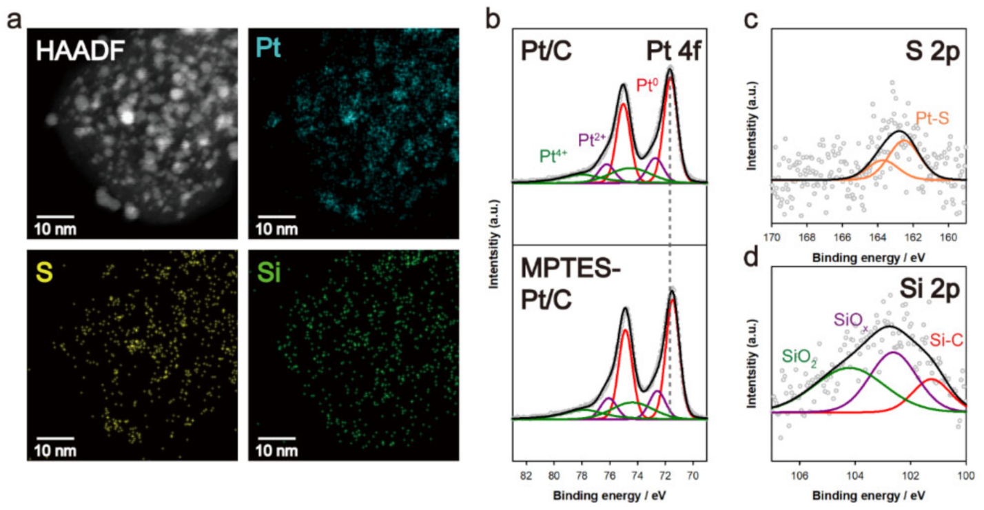
3.2. Elemental Analysis of MPTES–Pt/C

The adsorption of MPTES on Pt/C was conducted by immersing a commercial Pt/C in the MPTES solutions. The atomic ratio of sulfur of MPTES to Pt (S/Pt) was varied as 0, 4.2 × 10⁻³, 8.4 × 10⁻³, and 1.27 × 10⁻² (0, 5.16 × 10⁻³, 1.03 × 10⁻², and 1.55 × 10⁻² in MPTES/Pt weight ratio, respectively). The MPTES-treated Pt/Cs are denoted as 0-, 4.2-, 8.4-, and 12.7-MPTES–Pt/C based on their input S/Pt atomic ratios. The adsorption of MPTES on Pt/C was confirmed by STEM-EDS analysis (Figure 3a). The bright regions of the HAADF image correspond to Pt NPs. The S and Si elemental mapping images of 8.4-MPTES–Pt/C were perfectly superimposed with the Pt in the HAADF image, indicating that MPTES was adsorbed on the Pt surface rather than on the carbon, due to the large contrast in adsorption energy [28]. This was also verified for 4.2- and 12.7-MPTES–Pt/C in Figure S1. For the significant signals, 12.7-MPTES–Pt/C with excessive MPTES adsorption was measured by XPS. The Pt 4f XPS spectrum of MPTES–Pt/C was compared with that of Pt/C (Figure 3b). The Pt 4f 7/2 peak shifted from 71.7 to 71.6 eV with the MPTES adsorption due to the charge transfer from the adsorbed sulfur atoms to Pt NPs [31,32]. In the S 2p signal of 8.4-MPTES–Pt/C (Figure 3c), the double peaks centered at 162.5 and 163.8 eV represent the metal–sulfur bonding, again verifying the formation of Pt–S bonding between MPTES to Pt NP. The Si 2p XPS spectrum of 8.4-MPTES–Pt/C (Figure 3d) shows the presence of organic silicon (Si-C, 101.2 eV), silicon oxide (SiOx, 0 < x < 2, 102.6 eV), and silicon dioxide (SiO2, 104.3 eV) [33,34]. The organic silicon peak originates from the Si–C bond in MPTES, and the silicon oxide and dioxide peak confirm the formation of Si–O–Si bonds by hydrolysis of the silane-functional group.

3.3. Electrochemical Analysis of MPTES–Pt/C

Achieving facet-preferential MPTES adsorption presents a major challenge in this work. To investigate the adsorption site preference, cyclic voltammograms (CVs) were recorded with the MPTES–Pt/Cs with different MPTES/Pt ratios. As shown in the CV curve of the pristine Pt/C (Figure 4a), the desorption of chemisorbed hydrogen generates an oxidation current in the potential range of 0.05 to 0.40 V. Depending on the Pt surface facet, the potential for the hydrogen desorption varies, as indicated in the figure. The low coordinated edge and corner sites with Pt (110) step arrangement showed a broad oxidation peak centered at 0.16 V (peak one) and high coordinated terrace sites ((111), (100)) at 0.25 V (peak two) [35]. Since these peaks are significantly overlapped, the passivation of either site can lead to a reduction in these peaks, hindering quantitative analysis. However, monitoring of the relative variation of the two peaks with increasing MPTES content provides a qualitative verification of the facet-selectivity. For a perfect cubo-octahedral structure with a diameter of 3 nm, the surface atomic fraction of the LCSs is theoretically 30%, as shown in Figure 4b [10]. Therefore, when MPTES is preferentially adsorbed on the LCSs, 30% ECSA loss occurs for the ideal 3 nm-sized Pt NP structure. However, considering a steric hindrance of the pre-adsorbed MPTES to the adsorption of MPTES on nearby Pt sites, MPTESs cannot adsorb to all the Pt atoms of LCSs, resulting in partial passivation of the edge sites in practice.
As shown in Figure 4c, upon increasing the MPTES/Pt ratio from 0 to 8.4 × 10⁻³, the oxidation currents at peak one were further reduced rather than that at peak two. This strongly implies that the LCSs are preferentially passivated by MPTES for 8.4-MPTES–Pt/C. Interestingly, at a higher MPTES/Pt ratio of 1.27 × 10⁻², the oxidation current at peak one was not varied, but that at peak two was reduced. This means that the MPTES added to 8.4-MPTES–Pt/C is adsorbed mainly on the terrace sites, because, at a certain degree of MPTES adsorption, the pre-adsorbed MPTESs, which are densely populated on the LCSs, sterically prevent further MPTES adsorption on the edge and corner sites. The specific information of the CV curves and the relative ratio change of current at peak two and peak one by MPTES/Pt ratio is shown in Figure S2a–c. From the amount of charge from hydrogen desorption in the potential range of 0.05 to 0.4 V, ECSA was measured for various MPTES–Pt/C catalysts. As shown in Figure 4d, ECSA gradually decreased with the MPTES amount; however, the rate of decrease was considerably reduced, indicating the decrease in active LCSs with the MPTES amount. These results collectively support the hypothesis that MPTES preferentially reacts with the LCSs.
Considering the catalytic activity of the Pt catalyst, the ECSA loss caused by MPTES adsorption can be detrimental to ORR activity. In this regard, ORR polarization was measured for the various MPTES–Pt/C catalysts (Figure 4e), and their mass and specific activities were determined (Figure 4f,g, respectively). The magnified ORR polarization curves at the kinetic region near 0.90 V vs. RHE were shown in Figure S2d. In spite of the large differences in ECSA, the ORR mass activities varied weakly, which is of practical importance. Despite the 33% decrease in ECSA, 8.4-MPTES–Pt/C exhibited a mass activity loss of merely 3.3%. The comparison of specific activity shows a volcano-curve, as shown in Figure 4g; 8.4-MPTES–Pt/C showed the highest specific activity. This behavior can be explained in terms of the facet-dependency of ORR activity [14] and the electronic effect of adsorbed sulfur [36]. The LCSs have lower ORR activity compared with the high coordinated sites (HCSs) due to their high oxygen binding energies. Therefore, the increase in the relative surface fraction of HCSs by the passivation of LCSs leads to increased specific activity.

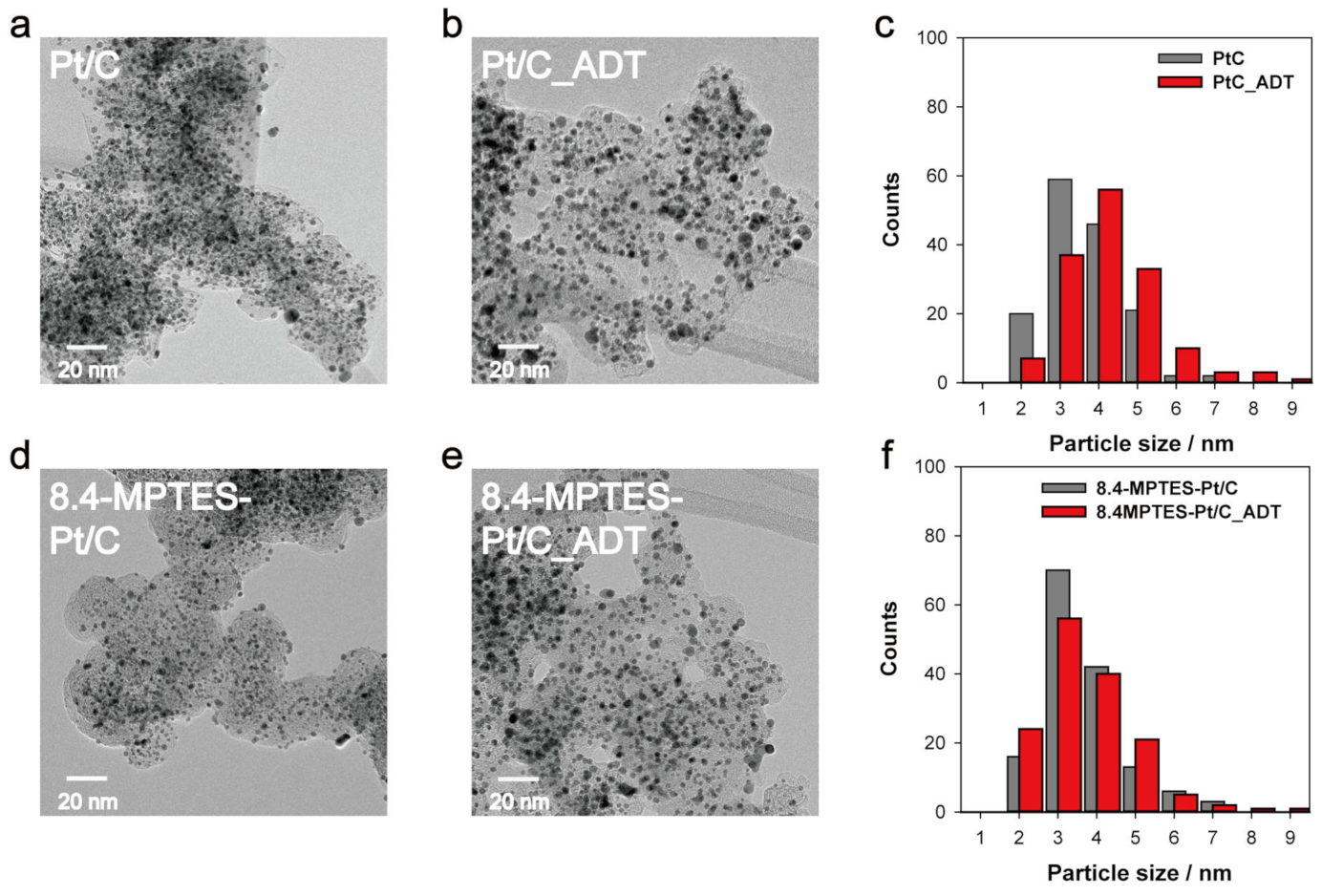
3.4. ADT Results and Post-Mortem Analysis

Pt dissolution stability was assessed for the Pt/C and various MPTES–Pt/Cs using the accelerated degradation test (ADT) protocol (30,000 potential cycles between 0.6–1.0 V at a scan rate of 100 mV s−1). CV and ORR polarization curves of Pt/C and 8.4-MPTES–Pt/C before and after ADT are compared in Figure 5a–d. The results for the other MPTES–Pt/C catalysts are displayed in Figure S3. As shown in Figure 5a, Pt/C showed a significant ECSA loss during the ADT, resulting in an ECSA retention of 62.7%. Due to the ECSA loss, the ORR activity also decreased, as shown in Figure 5b; the half-wave potential was shifted negative by 13 mV after 30,000 cycles. By sharp contrast, 8.4-MPTES–Pt/C showed a considerable improvement in terms of Pt dissolution stability. After ADT, the ECSA retention and negative shift for 8.4-MPTES–Pt/C were 94.4% and 5 mV, respectively. The durability was enhanced 6.7-fold in terms of ECSA loss and 2.6-fold in terms of negative shift, emphasizing the efficacy of the preferential protection strategy in enhancing the Pt dissolution stability.
With an increasing MPTES/Pt ratio, the Pt dissolution stability was improved, as indicated by the increased ECSA retention (Figure 5e) and mass activity retention (Figure 5f) with MPTES/Pt ratio. These results clearly demonstrate that the vulnerable LCSs are effectively protected by the MPTES-derived silica framework. As indicated by the MPTES/Pt effects, the amount of surface protection should be optimized considering the balance between the initial activity and durability. Considering the large difference in ORR activity and a small difference in activity retention between 8.4- and 12.7- MPTES–Pt/Cs, the 8.4-MPTES–Pt/C can be regarded as the optimum MPTES content.
In general, the voltage cycling test results in the growth of Pt NPs, due to Pt dissolution and Oswald ripening [37,38]. Therefore, the degree of Pt particle-size change with ADT is indicative of the Pt dissolution stability. To investigate the size change, TEM images were collected before and after ADT for Pt/C and 8.4-MPTES–Pt/C, and their Pt size distributions were obtained, as shown in Figure 6a–f. Before ADT, Pt/C and 8.4-MPTES–Pt/C had similar particle sizes (~3.0 nm). However, the average particle size was increased to 3.77 nm for Pt/C and 3.11 nm for 8.4-MPTES–Pt/C. A significant broadening of the size distribution was observed after ADT for Pt/C; by contrast, the size distribution was not changed for 8.4-MPTES–Pt/C. The nearly invariant Pt particle size and distribution for 8.4-MPTES–Pt/C again confirms the suppression of Pt dissolution by the facet-preferential molecular protection. STEM-EDS analysis for 8.4-MPTES–Pt/C after ADT verifies the stability of the silica framework, shown in Figure S4. The S and Si elemental mapping images of S and Si are consistent with the Pt images, indicating that the MPTES-derived silica framework remains at the Pt surfaces.
The introduction of the silica framework plays an important role in achieving high durability. To verify the positive function of the silica framework, the preferential protection of LCSs with 1-butanethiol (BT) was compared. A proper amount of BT was treated on Pt/C to obtain identical ECSA loss of 30% between 8.4-MPTES–Pt/C and BT-Pt/C. The CV and ORR polarization curves for BT-Pt/C before and after ADT are compared in Figure S5a,b, respectively. For BT-Pt/C, ECSA loss (30.6%) and ORR loss (20 mV) were comparable to those of bare Pt/C (37.3% and 13 mV) but much larger than those of 8.4-MPTES–Pt/C (94.4% and 5 mV). The difference in ECSA loss between 8.4-MPTES–Pt/C and BT-Pt/C clearly shows that, without the silica framework, the adsorbed thiol compound can be removed from the Pt surface.

4. Conclusions

In summary, we successfully demonstrated the preferential protection of vulnerable low coordinated edge and corner sites by exploiting the thiol adsorption and silica formation of MPTES. Physical and electrochemical analyses indicated that MPTES adsorbs onto the Pt nanoparticle surface with high facet selectivity and effectively protects the LCSs while minimizing the passivation of relatively stable and electrochemically active terrace sites. The preferential protection of LCSs did not cause a significant reduction in ORR activity, in spite of a considerable ECSA loss due to the increased specific activity by charge transfer from sulfur atoms. As a result of the atomic scale protection, Pt dissolution stability was notably enhanced by 6.7-fold in terms of ECSA loss. The MPTES-derived silica framework was stable under PEMFC operating conditions. Based on the simplicity, marginal loss of initial ORR activity, excellent Pt dissolution stability, and applicability to commercial Pt/C, the judicious engineering of atomistic Pt surface protection offers a novel platform for high-performance Pt catalysts for practical fuel cells.

Supplementary Materials

The following are available online at https://0-www-mdpi-com.brum.beds.ac.uk/1996-1073/14/5/1419/s1, Figure S1: STEM-EDS HAADF and elemental mapping images with varying MPTES/Pt ratio; Figure S2: Additional information obtained from electrochemical analysis with varying MPTES/Pt ratio; Figure S3: Accelerated durability test results with varying MPTES/Pt ratio; Figure S4: STEM-EDS HAADF and elemental mapping images of 8.4-MPTES–Pt/C after ADT; Figure S5: Electrochemical analysis results of 1-butanethiol adsorbed-Pt/C; Figure S6: XPS analysis of Pt/C treated with excess amount of MPTES.

Author Contributions

D.W.L. designed the experiments, conducted experiments and analyses, and wrote the manuscript; S.Y., S.C., D.-H.L. and G.D. contributed to conceptualize the work and interpret the experimental data; J.H. and J.K. contributed to assist the experiment and analyses; H.-T.K. and J.Y.K. supervised the research. All authors contributed to the writing and review of the manuscript. All authors have read and agreed to the published version of the manuscript.

Funding

This research was supported by the KOLON-KAIST Lifestyle Innovation Center (LSI10-MAKHT0001) through the KOLON Corporation, Korea and KAIST, and by the Technology Development Program to Solve Climate Change of the National Research Foundation (NRF) funded by the Ministry of Science, ICT & Future Planning (NRF-2015M1A2A2057127 and NRF-2015M1A2A2056733).

Institutional Review Board Statement

Not applicable.

Informed Consent Statement

Not applicable.

Conflicts of Interest

The authors declare no conflict of interest.

References

  1. Steele, B.C.H.; Heinzel, A. Materials for fuel-cell technologies. Nature 2001, 414, 345–352. [Google Scholar] [CrossRef] [PubMed]
  2. Winter, M.; Brodd, R.J. What Are Batteries, Fuel Cells, and Supercapacitors? Chem. Rev. 2004, 104, 4245–4270. [Google Scholar] [CrossRef] [PubMed] [Green Version]
  3. Qiu, L.; Liu, F.; Zhao, L.; Yang, W.; Yao, J. Evidence of a Unique Electron Donor−Acceptor Property for Platinum Nanoparticles as Studied by XPS. Langmuir 2006, 22, 4480–4482. [Google Scholar] [CrossRef]
  4. Yu, K.; Groom, D.J.; Wang, X.; Yang, Z.; Gummalla, M.; Ball, S.C.; Myers, D.J.; Ferreira, P.J. Degradation Mechanisms of Platinum Nanoparticle Catalysts in Proton Exchange Membrane Fuel Cells: The Role of Particle Size. Chem. Mater. 2014, 26, 5540–5548. [Google Scholar] [CrossRef]
  5. Meier, J.C.; Galeano, C.; Katsounaros, I.; Witte, J.; Bongard, H.J.; Topalov, A.A.; Baldizzone, C.; Mezzavilla, S.; Schüth, F.; Mayrhofer, K.J.J. Design criteria for stable Pt/C fuel cell catalysts. Beilstein J. Nanotechnol. 2014, 5, 44–67. [Google Scholar] [CrossRef] [PubMed] [Green Version]
  6. Sharma, R.; Andersen, S.M. Quantification on Degradation Mechanisms of Polymer Electrolyte Membrane Fuel Cell Catalyst Layers during an Accelerated Stress Test. ACS Catal. 2018, 8, 3424–3434. [Google Scholar] [CrossRef] [Green Version]
  7. Tang, L.; Han, B.; Persson, K.; Friesen, C.; He, T.; Sieradzki, K.; Ceder, G. Electrochemical Stability of Nanometer-Scale Pt Particles in Acidic Environments. J. Am. Chem. Soc. 2010, 132, 596–600. [Google Scholar] [CrossRef]
  8. Cherevko, S.; Kulyk, N.; Mayrhofer, K.J.J. Durability of platinum-based fuel cell electrocatalysts: Dissolution of bulk and nanoscale platinum. Nano Energy 2016, 29, 275–298. [Google Scholar] [CrossRef]
  9. Calle-Vallejo, F.; Tymoczko, J.; Colic, V.; Vu, Q.H.; Pohl, M.D.; Morgenstern, K.; Loffreda, D.; Sautet, P.; Schuhmann, W.; Bandarenka, A.S. Finding optimal surface sites on heterogeneous catalysts by counting nearest neighbors. Science 2015, 350, 185–189. [Google Scholar] [CrossRef]
  10. Lopes, P.P.; Strmcnik, D.; Tripkovic, D.; Connell, J.G.; Stamenkovic, V.; Markovic, N.M. Relationships between Atomic Level Surface Structure and Stability/Activity of Platinum Surface Atoms in Aqueous Environments. ACS Catal. 2016, 6, 2536–2544. [Google Scholar] [CrossRef]
  11. Subramanian, N.P.; Greszler, T.A.; Zhang, J.; Gu, W.; Makharia, R. Pt-Oxide Coverage-Dependent Oxygen Reduction Reaction (ORR) Kinetics. J. Electrochem. Soc. 2012, 159, B531–B540. [Google Scholar] [CrossRef]
  12. Chung, D.Y.; Shin, H.; Yoo, J.M.; Lee, K.-S.; Lee, N.-S.; Kang, K.; Sung, Y.-E. Functional link between surface low-coordination sites and the electrochemical durability of Pt nanoparticles. J. Power Sources 2016, 334, 52–57. [Google Scholar] [CrossRef]
  13. Sandbeck, D.J.S.; Brummel, O.; Mayrhofer, K.J.J.; Libuda, J.; Katsounaros, I.; Cherevko, S. Dissolution of Platinum Single Crystals in Acidic Medium. ChemPhysChem 2019, 20, 2997–3003. [Google Scholar] [CrossRef] [Green Version]
  14. Stephens, I.E.L.; Bondarenko, A.S.; Grønbjerg, U.; Rossmeisl, J.; Chorkendorff, I. Understanding the electrocatalysis of oxygen reduction on platinum and its alloys. Energy Environ. Sci. 2012, 5, 6744–6762. [Google Scholar] [CrossRef] [Green Version]
  15. Takahashi, S.; Chiba, H.; Kato, T.; Endo, S.; Hayashi, T.; Todoroki, N.; Wadayama, T. Oxygen reduction reaction activity and structural stability of Pt–Au nanoparticles prepared by arc-plasma deposition. Phys. Chem. Chem. Phys. 2015, 17, 18638–18644. [Google Scholar] [CrossRef]
  16. Cai, J.; Zhang, J.; Cao, K.; Gong, M.; Lang, Y.; Liu, X.; Chu, S.; Shan, B.; Chen, R. Selective Passivation of Pt Nanoparticles with Enhanced Sintering Resistance and Activity toward CO Oxidation via Atomic Layer Deposition. ACS Appl. Nano Mater. 2018, 1, 522–530. [Google Scholar] [CrossRef]
  17. Jiang, Z.-Z.; Wang, Z.-B.; Gu, D.-M.; Smotkin, E.S. Carbon riveted Pt/C catalyst with high stability prepared by in situ carbonized glucose. Chem. Commun. 2010, 46, 6998–7000. [Google Scholar] [CrossRef]
  18. Lee, H.; Sung, Y.-E.; Choi, I.; Lim, T.; Kwon, O.J. Novel synthesis of highly durable and active Pt catalyst encapsulated in nitrogen containing carbon for polymer electrolyte membrane fuel cell. J. Power Sources 2017, 362, 228–235. [Google Scholar] [CrossRef]
  19. Chung, D.Y.; Jun, S.W.; Yoon, G.; Kwon, S.G.; Shin, D.Y.; Seo, P.; Yoo, J.M.; Shin, H.; Chung, Y.-H.; Kim, H.; et al. Highly Durable and Active PtFe Nanocatalyst for Electrochemical Oxygen Reduction Reaction. J. Am. Chem. Soc. 2015, 137, 15478–15485. [Google Scholar] [CrossRef] [PubMed]
  20. Chung, S.; Choun, M.; Jeong, B.; Lee, J.K.; Lee, J. Atomic layer deposition of ultrathin layered TiO2 on Pt/C cathode catalyst for extended durability in polymer electrolyte fuel cells. J. Energy Chem. 2016, 25, 258–264. [Google Scholar] [CrossRef]
  21. Cheng, N.; Banis, M.N.; Liu, J.; Riese, A.; Li, X.; Li, R.; Ye, S.; Knights, S.; Sun, X. Extremely Stable Platinum Nanoparticles Encapsulated in a Zirconia Nanocage by Area-Selective Atomic Layer Deposition for the Oxygen Reduction Reaction. Adv. Mater. 2015, 27, 277–281. [Google Scholar] [CrossRef]
  22. Takenaka, S.; Matsumori, H.; Nakagawa, K.; Matsune, H.; Tanabe, E.; Kishida, M. Improvement in the Durability of Pt Electrocatalysts by Coverage with Silica Layers. J. Phys. Chem. C 2007, 111, 15133–15136. [Google Scholar] [CrossRef]
  23. Takenaka, S.; Miyamoto, H.; Utsunomiya, Y.; Matsune, H.; Kishida, M. Catalytic Activity of Highly Durable Pt/CNT Catalysts Covered with Hydrophobic Silica Layers for the Oxygen Reduction Reaction in PEFCs. J. Phys. Chem. C 2014, 118, 774–783. [Google Scholar] [CrossRef]
  24. Aoki, N.; Inoue, H.; Kawasaki, H.; Daimon, H.; Doi, T.; Inaba, M. Durability Improvement of Pd Core-Pt Shell Structured Catalyst by Porous SiO2 Coating. J. Electrochem. Soc. 2018, 165, F737–F747. [Google Scholar] [CrossRef]
  25. Choi, J.; Jang, J.-H.; Roh, C.-W.; Yang, S.; Kim, J.; Lim, J.; Yoo, S.J.; Lee, H. Gram-scale synthesis of highly active and durable octahedral PtNi nanoparticle catalysts for proton exchange membrane fuel cell. Appl. Catal. B Environ. 2018, 225, 530–537. [Google Scholar] [CrossRef] [Green Version]
  26. Bu, L.; Feng, Y.; Yao, J.; Guo, S.; Guo, J.; Huang, X. Facet and dimensionality control of Pt nanostructures for efficient oxygen reduction and methanol oxidation electrocatalysts. Nano Res. 2016, 9, 2811–2821. [Google Scholar] [CrossRef]
  27. Turchanin, A.; El-Desawy, M.; Gölzhäuser, A. High thermal stability of cross-linked aromatic self-assembled monolayers: Nanopatterning via selective thermal desorption. Appl. Phys. Lett. 2007, 90, 053102. [Google Scholar] [CrossRef]
  28. Chung, D.Y.; Lee, M.J.; Kim, M.; Shin, H.; Kim, M.-J.; Yoo, J.M.; Park, S.; Sung, Y.-E. CO electro-oxidation reaction on Pt nanoparticles: Understanding peak multiplicity through thiol derivative molecule adsorption. Catal. Today 2017, 293–294, 2–7. [Google Scholar] [CrossRef]
  29. Dablemont, C.; Lang, P.; Mangeney, C.; Piquemal, J.-Y.; Petkov, V.; Herbst, F.; Viau, G. FTIR and XPS Study of Pt Nanoparticle Functionalization and Interaction with Alumina. Langmuir 2008, 24, 5832–5841. [Google Scholar] [CrossRef]
  30. Genorio, B.; Strmcnik, D.; Subbaraman, R.; Tripkovic, D.; Karapetrov, G.; Stamenkovic, V.R.; Pejovnik, S.; Marković, N.M. Selective catalysts for the hydrogen oxidation and oxygen reduction reactions by patterning of platinum with calix[4]arene molecules. Nat. Mater. 2010, 9, 998–1003. [Google Scholar] [CrossRef]
  31. Wang, S.; Yang, F.; Jiang, S.P.; Chen, S.; Wang, X. Tuning the electrocatalytic activity of Pt nanoparticles on carbon nanotubes via surface functionalization. Electrochem. Commun. 2010, 12, 1646–1649. [Google Scholar] [CrossRef]
  32. Kim, T.-J.; Kwon, G.; Kim, Y.-T. Anomalously increased oxygen reduction reaction activity with accelerated durability test cycles for platinum on thiolated carbon nanotubes. Chem. Commun. 2014, 50, 596–598. [Google Scholar] [CrossRef] [PubMed]
  33. Dietrich, P.M.; Glamsch, S.; Ehlert, C.; Lippitz, A.; Kulak, N.; Unger, W.E.S. Synchrotron-radiation XPS analysis of ultra-thin silane films: Specifying the organic silicon. Appl. Surf. Sci. 2016, 363, 406–411. [Google Scholar] [CrossRef]
  34. Darmakkolla, S.R.; Tran, H.; Gupta, A.; Rananavare, S.B. A method to derivatize surface silanol groups to Si-alkyl groups in carbon-doped silicon oxides. RSC Adv. 2016, 6, 93219–93230. [Google Scholar] [CrossRef]
  35. Wadayama, T.; Yoshida, H.; Ogawa, K.; Todoroki, N.; Yamada, Y.; Miyamoto, K.; Iijima, Y.; Sugawara, T.; Arihara, K.; Sugawara, S.; et al. Outermost Surface Structures and Oxygen Reduction Reaction Activities of Co/Pt(111) Bimetallic Systems Fabricated Using Molecular Beam Epitaxy. J. Phys. Chem. C 2011, 115, 18589–18596. [Google Scholar] [CrossRef]
  36. Park, I.-S.; Tong, Y.Y.J. Sulfide–Adsorption-Enhanced Oxygen Reduction Reaction on Carbon-Supported Pt Electrocatalyst. Electrocatalysis 2013, 4, 117–122. [Google Scholar] [CrossRef]
  37. Ferreira, P.J.; la O’, G.J.; Shao-Horn, Y.; Morgan, D.; Makharia, R.; Kocha, S.; Gasteiger, H.A. Instability of Pt ∕ C Electrocatalysts in Proton Exchange Membrane Fuel Cells: A Mechanistic Investigation. J. Electrochem. Soc. 2005, 152, A2256–A2271. [Google Scholar] [CrossRef] [Green Version]
  38. Meier, J.C.; Galeano, C.; Katsounaros, I.; Topalov, A.A.; Kostka, A.; Schüth, F.; Mayrhofer, K.J.J. Degradation Mechanisms of Pt/C Fuel Cell Catalysts under Simulated Start–Stop Conditions. ACS Catal. 2012, 2, 832–843. [Google Scholar] [CrossRef]
Figure 1. Facet-preferential protection of Pt nanoparticle. Schematic of (a), Pt dissolution at low coordinated Pt sites, (b), the preferential adsorption of (3-mercaptopropyl) triethoxysilane (MPTES) on edge and corner sites, and (c), the subsequent conversion of MPTES to silicon framework.
Energies 14 01419 g001
Figure 2. Theoretical computations of the adsorption energy of MPTES on Pt (111), (100), and (211) surfaces.
Energies 14 01419 g002
Figure 3. (a) Scanning transmission electron microscopy-energy dispersive X-ray spectroscopy (STEM-EDS), high-angle annular dark-field (HAADF) image, and Pt, S, and, Si elemental mapping images of 8.4-MPTES–Pt/C. (b) Pt 4f XPS spectra of Pt/C and 8.4-MPTES–Pt/C. (c) S 2p and (d) Si 2p XPS spectra of 8.4-MPTES–Pt/C.
Energies 14 01419 g003
Figure 4. (a) Typical cyclic voltammetry (CV) curve of Pt/C. (b) Calculated surface atomic fractions of edge and vertex sites, (111) and (100) terrace sites for ideal cubo-octahedral Pt platinum nanoparticles (NPs) with various sizes, reproduced from [10]. (c) CV curves and (d) initial electrochemical surface area (ECSA) values for Pt/C and MPTES–Pt/Cs with different MPTES/Pt ratios. (e) Oxygen reduction reaction (ORR) polarization curves and comparison of (f) mass and (g) specific activity calculated from the kinetic current at 0.9 V for Pt/C and MPTES–Pt/Cs with different MPTES/Pt ratios.
Energies 14 01419 g004
Figure 5. CV and ORR polarization curves before and after an accelerated degradation test (ADT) for (a), (b) Pt/C and (c), (d) 8.4-MPTES–Pt/C. Retention of (e) ECSA and (f) mass activity for MPTES–Pt/Cs with different MPTES/Pt ratios.
Energies 14 01419 g005
Figure 6. High-resolution transmission electron microscopy (HR-TEM) images and particle size distribution histograms before and after ADT for (ac) Pt/C and (df) 8.4-MPTES–Pt/C.
Energies 14 01419 g006
Publisher’s Note: MDPI stays neutral with regard to jurisdictional claims in published maps and institutional affiliations.

