
Treatment of Flue Gas in a CO2 Capture Pilot Plant for a Commercial CFB Boiler
by
 , ,
, ,
Izabela Majchrzak-Kucęba
1,* ,
,
Dariusz Wawrzyńczak
1,
Janusz Zdeb
2,
Wojciech Smółka
2 and
Artur Zajchowski
2 1
Department of Advanced Energy Technologies, Faculty of Infrastructure and Environment, Czestochowa University of Technology, Dabrowskiego Street 73, 42-201 Czestochowa, Poland
2
TAURON Wytwarzanie S.A., Promienna Street 51, 43-603 Jaworzno, Poland
*
Author to whom correspondence should be addressed.
Energies 2021, 14(9), 2458; https://0-doi-org.brum.beds.ac.uk/10.3390/en14092458
Submission received: 16 March 2021
/
Revised: 22 April 2021
/
Accepted: 24 April 2021
/
Published: 26 April 2021
(This article belongs to the Special Issue Progress and Novel Applications of Fluidized Bed Technology)
Abstract
:The problem of reducing carbon dioxide emissions from flue gas, particularly from flue gas originating from coal-firing CFB systems, is currently an important challenge. Many centers around the world have tested post-combustion CO2 capture systems. One of these systems, operated using DR-VPSA adsorption technology (dual-reflux vacuum pressure swing adsorption), was tested under the Strategic Project in Poland. The flue gas in this study originated from a supercritical CFB boiler (460 MWe). An important problem involved in capturing CO2 from flue gas is the occurrence of SO2 and NOx. These substances have a negative effect on the CO2 adsorption process. In this study, commercial impregnated activated carbon was used to remove SO2 and NOx from CFB flue gas in the pre-treatment section during the tests of a pilot CO2 capture unit in a large-scale CFB boiler at the Lagisza Power Plant (Poland). The spent activated carbon was analyzed using several different methods (N2 adsorption–desorption isotherms, SEM-EDX, XRD, FTIR, and TG) to evaluate the efficiency of the operation and life span of the adsorbent used in the SO2 and NOx removal unit. The results demonstrate that using commercial impregnated activated carbon in the pre-treatment section ensures sufficient flue gas purification and the removal of sulfur oxides but remains insufficient for nitrogen oxides.

1. Introduction
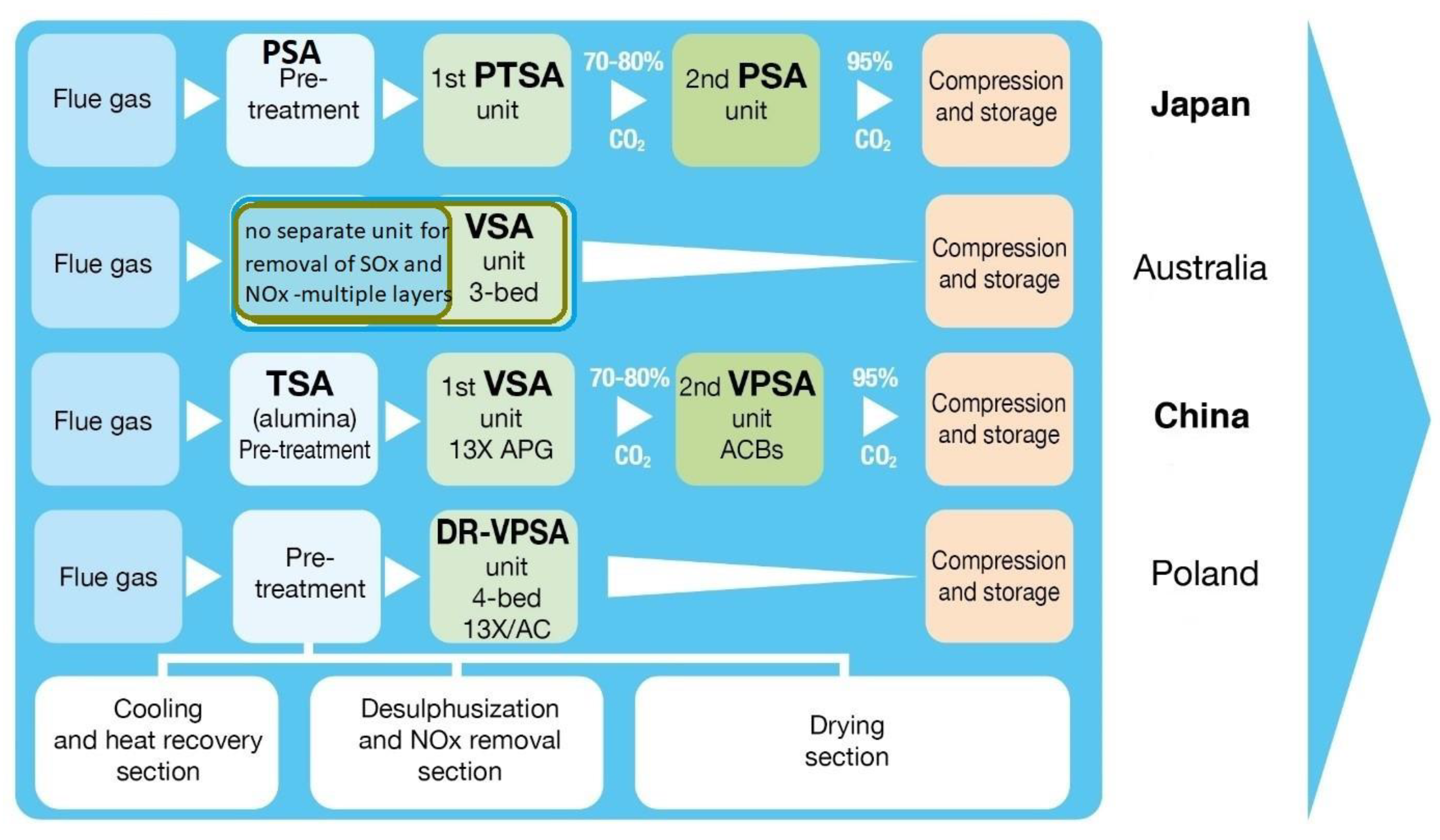
Reducing the emissions of CO2 and other greenhouse gases contributing to global warming is a global challenge. Among the many proposed CO2 emission reduction solutions is CCSU (carbon capture and storage/utilization), which enables CO2 to be captured and then stored or utilized by processing it into a usable product such as methanol using renewable energy sources [1,2]. The most developed and advanced CO2 capture technologies are amine-based absorption systems such as the large-scale absorption units operating at the coal-fired Boundary Dam power plant in Canada and at the coal-fired Petra Nova power plant in Texas in the United States [2]. Another dynamically developing CO2 capture technology is the solid adsorbent-based adsorption technique involving vacuum pressure swing adsorption (VPSA) technology [3,4,5,6,7,8,9]. To date, at a pilot scale and under real power plant conditions, adsorption units for CO2 capture on fixed beds have been tested in Japan [4,5], China [6], Australia [7], and Poland [8,9]. According to the tests carried out on all pilot adsorption CO2 capture units treating real flue gas [4,5,6,7,8,9], one of the most important factors influencing the effectiveness of CO2 adsorption is the content of H2O and other impurities such as SO2, NOx, dust, alkalis, and volatile metals in the flue gas [10,11,12,13,14,15,16]. These components have negative effects on the physical adsorbents used in the adsorption method (activated carbon [4,5,6,7,8,9,17,18,19], zeolites [4,5,6,7,8,9], metal–organic frameworks [20,21], and mesoporous silica [22]), thereby reducing their CO2 sorption capacity, which affects CO2 purity and recovery. Meanwhile, many growing present-day recycling methods for CO2 captured from power plants and other branches of industry require clean CO2 streams. Moreover, the presence of the above-listed impurities accelerates deactivation of the CO2 adsorbent, making more frequent replacement of the adsorbent necessary and thus increasing total costs of capturing CO2 from flue gas. Therefore, it is important to ensure the effective removal of SO2 and NOx from flue gas before the CO2 adsorption process because both SO2 and NOx can adsorb and/or react with CO2 adsorption materials [10,11,12,13,14,15,16,17,18,19]. Similar to amine-based absorption systems [23], the SO2 and NOx content in flue gas should be ca. 10 mg/Nm3 before the flue gas is sent to the CO2 adsorption unit, while the limits of SO2 and NOx emissions from flue gas needed for coal power plants in the EU are now 200 mg/Nm3 [24]. As a result, all pilot CO2 separation units described in the literature comprise pre-treatment sections designed to dry and purify flue gas, which primarily involves the removal of SO2 and NOx before it is sent to the CO2 capture section. This assignment is impacted by using various methods and adsorbents (Figure 1). Regrettably, there is little information concerning the functioning of these units, their efficiency, and the effectiveness of adsorbents used to remove SO2 and NOx [4,7]. For flue gas drying alongside the removal of SO2 and NOx in a pilot VPSA CO2 capture unit, Wang et al. [6] proposed a pre-treatment unit consisting of a two-column TSA (temperature swing adsorption) module in which 156 kg of alumina was used as the adsorbent [6]. This adsorbent was also used by Ishibasi et al. as a packing material in a PSA (pressure swing adsorption) unit employed as the pre-treatment section for flue gas drying and additional SO2 removal in an adsorption CO2 capture unit [4,5]. Studies demonstrated that in addition to adsorbing moisture, the applied alumina also co-adsorbed CO2. As a result of these tests, it was observed that in the primary stage, alumina acted as a moisture absorbent and also captured SO2 in the form of sulfuric acid and aluminum sulfate, which was found in an adsorbent taken from the bottom part of the adsorption column. It was demonstrated that this result did not affect dryer efficiency. The SO2 removal was so effective that no SO2 accumulation was observed in the CO2 adsorbent removed after 2000 h of use in a PTSA/PSA adsorption unit installed to capture CO2. These studies confirmed that the applied alumina worked as both a moisture adsorbent and as a filter protecting against SO2.
On the other hand, in the solution proposed by Qader et al. [7], no separate unit for the drying and removal of SO2 and NOx from flue gas was used, but the pre-treatment unit’s function was affected by an adsorber column with multiple layers, removing H2O/SO2/NOx in the first layer of the adsorbent and CO2 in the second layer [7]. Multi-layer adsorbents were applied in this solution: The first layer consisted of adsorbents used to remove water and SO2/NOx from flue gas, and the second consisted of adsorbents selective to CO2. This system’s functionality demonstrated that SO2 and NOx not captured from flue gas may cause blower corrosion induced by generated sulfuric acid. Thus, the elimination of SO2, NOx, and water from flue gas is required in the commercial use of adsorption installations for capturing CO2 because these impurities may negatively affect the functionality of the installation elements. A different solution was employed in a Polish installation [8] where the pre-treatment section consisted of three different subsections: a cooling and heat recovery section, desulfurization and NOx removal adsorbers, and a drying section. To date, only in this solution were far flue gas drying and the removal of SO2 and NOx carried out in separate sections. Another innovation was to use activated carbon impregnated with potassium hydroxide and potassium iodide for the simultaneous removal of SO2 and NOx [8]. This adsorbent was chosen because impregnated activated carbon was proposed, primarily for the simultaneous removal of SO2 and NOx. While the adsorption of gases on activated carbon is predominantly driven by physisorption, that of the modified carbon surface is driven by both physisorption and chemisorption. Modification of the AC surface is necessary to improve attraction between the adsorbent and target gases, resulting in a higher adsorption capacity of gases, especially at low gas concentrations in the flue gas. As an impregnating substance, KOH is known to have an excellent selective adsorption capacity for acid gases. An AC upgraded by impregnating it with KOH and KI promoted chemisorption with SO2 and NOx [25,26,27,28,29,30].
Moreover, no data are available on the use of activated carbon impregnated with KOH/KJ for the simultaneous removal of SO2 and NOx in pilot adsorption CO2 capture installations under the operational conditions of large-scale CFB facilities. Valuable pilot plant data from commercial CFB units are presented in this work. Only a few studies have been devoted to the impacts of impurities such as SO2 and NOx on CO2 adsorption by VSA (vacuum swing adsorption) [13] in the extant literature. Considering this factor, the present article focuses on assessing the efficiency of applied adsorbents in the removal of SO2 and NOx from flue gas prior to the CO2 removal process at the Lagisza Power Plant. To assess the efficiency of using impregnated activated carbon in pre-treatment units to remove SO2 and NOx from CFB (circulating fluidized bed) flue gas, a comprehensive analysis of the adsorbents was carried out before and after their use in the desulfurization and NOx removal section in a pilot adsorption (DR-VPSA) CO2 capture unit under typical flue gas conditions. Studies of this type have not been reported in the CFB literature. Many articles discuss and focus on H2O impacts on CO2 sorption in adsorption installations, but there are no detailed analyses regarding effective SOx and NOx removal from flue gas. The available literature rarely reports real CFB flue gas treatments. Studies of this type would not only help us understand the principles of impurity adsorption and the efficiency of applied adsorbents but would also provide valuable data for the design of adsorption-based demonstration CO2 capture installations. The purpose of the current research was to understand simultaneous SO2 and NOx adsorption on impregnated activated carbon at the stage of CFB flue gas pre-treatment in post-combustion CO2 capture. Evaluation of the desulfurization/denitrification mechanism was performed through spent activated carbon post-analysis.
2. Experimental Section
2.1. Pre-Treatment Section in a Pilot-Scale DR-VPSA Carbon Capture Unit
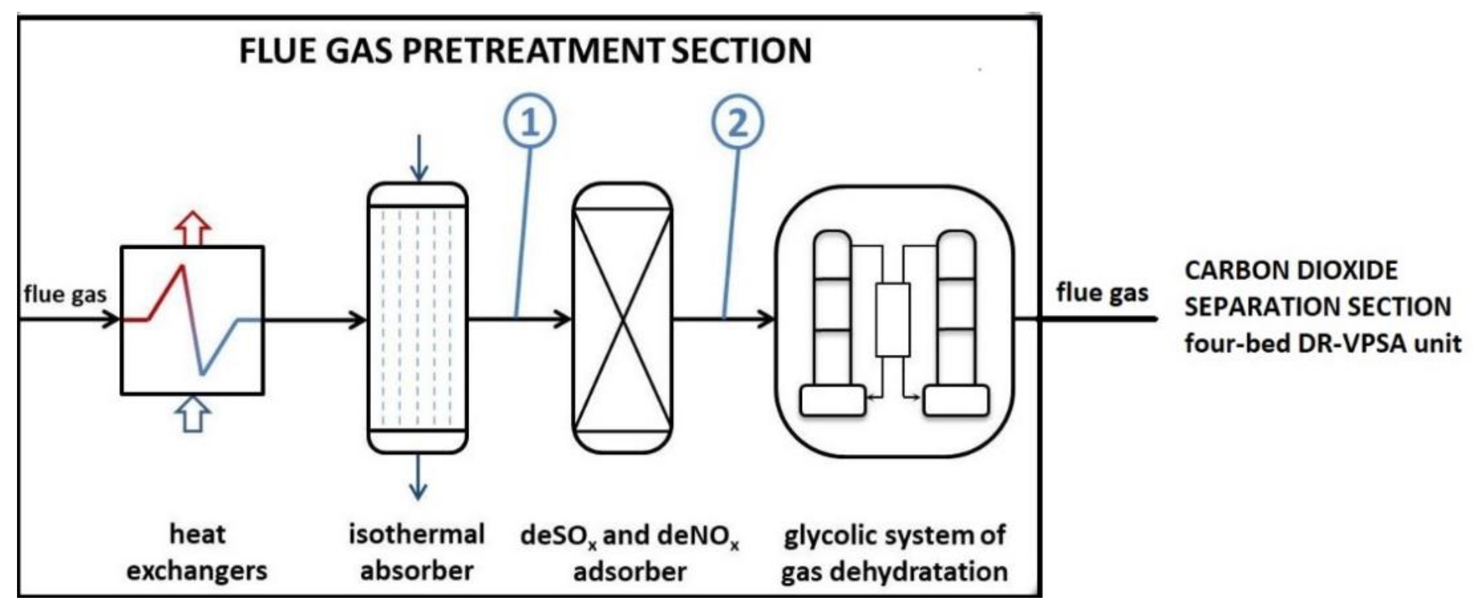
In 2015–2016, under the Strategic Project financed by NCBiR (the National Centre for Research and Development) in Poland, research was carried out on post-combustion CO2 capture in a pilot DR-VPSA mobile unit located at Tauron Wytwarzanie S.A.—The Lagisza Power Plant in Poland. The flue gas originated from the world’s first supercritical CFB boiler (460 MWe). The mobile CO2 capture unit consisted of a flue gas pre-treatment section and a carbon dioxide separation section (four-bed DR-VPSA) (Figure 2). In the proposed solution, a complex pre-treatment section was used for the first time and compared to other pilot CO2 adsorption units [4,5,6,7]. The pre-treatment unit consisted of heat exchangers, an isothermal absorber, a deSOx and deNOx adsorber, and a glycolic gas dehydration system. The CO2 separation unit consisted of four two-section adsorbers [8]. Detailed information about the mobile pilot DR-VPSA unit and the performed tests is available in previous studies [8,9]. The present article focuses only on the functionality of desulfurization and the NOx removal adsorber, which is an element of the flue gas pre-treatment section. More specifically, this study focuses on evaluating the desulfurization/denitrification mechanism through spent activated carbon post-analysis.
Before the flue gas generated in Lagisza Power Plant was sent to the pilot four-bed DR-VPSA unit, the following impurities were removed from the gas at the plant: SO2, using a dry desulfurization method, and NOx, using selective, non-catalytic reduction. The resulting average SO2 and NOx content in the flue gas from the CFB boiler was as follows: SO2 of 154.6 mg/Nm3 and NOx of 179.8 mg/Nm3 [8]. These content levels satisfy the applicable emission standards for these gases but remain too high for CO2 capture units. As a result, the CO2 capture installations need a pre-treatment section to reduce the SO2 and NOx from the flue gas to ca. 10 mg/Nm3. Effective SO2 and NOx removal in this section is essential because this removal affects the purity of the CO2 captured in the CO2 separation unit [9], which is important for recycling the obtained CO2 stream. Many of the proposed recycling methods require a high-purity CO2 stream. For example, NOx can be a problem in the CO2 stream if the stream is intended to be used in the food and beverage industry.
2.2. Characterization of the Adsorbent Used in the deSOx and deNOx Adsorber
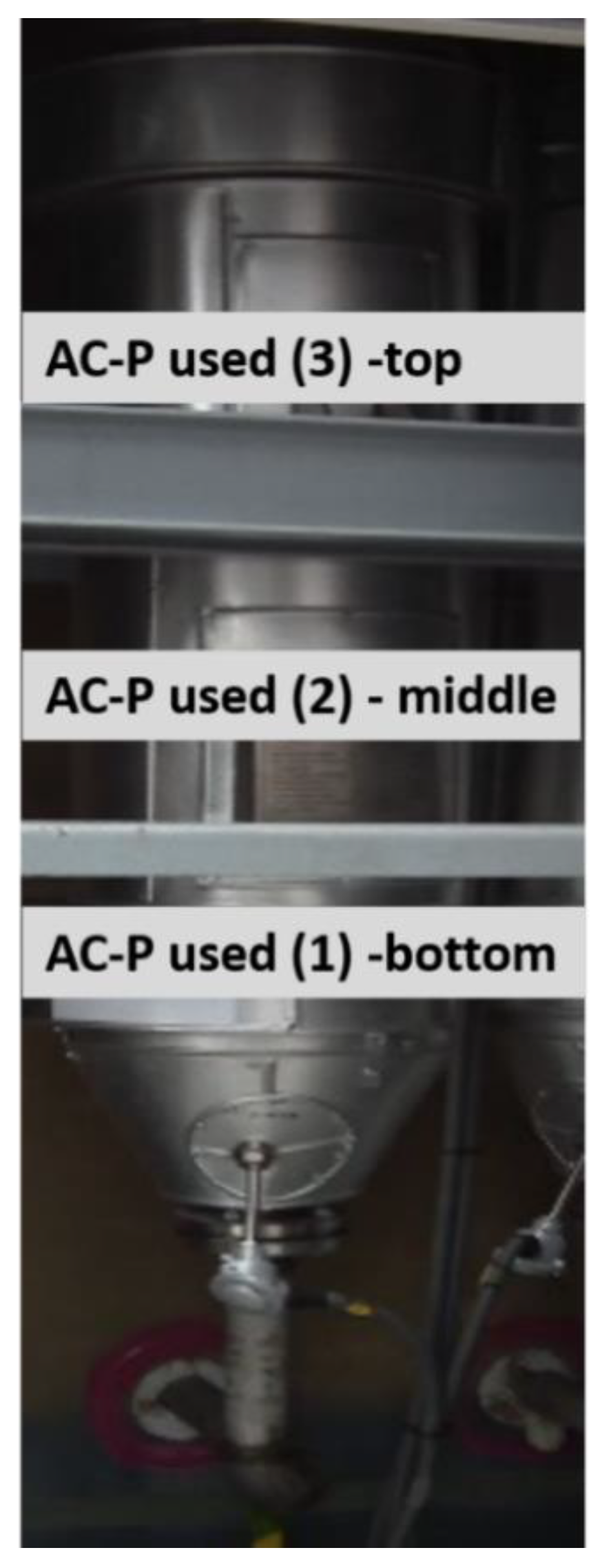
Activated carbon (AC-P) Airpel 10 impregnated with potassium iodide KI (ca. 2 wt.%) and KOH (ca. 3 wt.%) manufactured by DESOTEC Activated Carbon was used for the simultaneous removal of SO2 and NOx in the flue gas pre-treatment section pilot DR-VPSA CO2 capture unit. This carbon (130 kg) was used as packing in the deSOx and deNOx adsorber (Figure 3). The activated carbon (AC-P) in this study was granulated activated carbon produced from anthracite with a pellet radius of >2.36 (99% mass), density of 520 kg/m3, water vapor capacity of 40.1%, and a highly developed surface of 959 m2/g. While the adsorption of gases on porous activated carbon is driven primarily by physical adsorption, in the case of a modified carbon surface (KOH), the adsorption of gases is driven by both physical adsorption and chemisorption with a chemical reaction between the surface function groups and adsorbed gases. AC surface modification is necessary to improve the pull between the adsorbent and gases, especially when the gas concentration in flue gases is low. This type of modification is required to increase the alkalinity and general chemistry of the carbon surface under the pull of strongly polarized SO2 gas. Potassium iodide performs the role of an “oxygen carrier”. The deSOx and deNOx adsorber was designed to reduce SO2 to ca. 10 mg/Nm3 and NOx to 40 mg/Nm3. The deSOx and deNOx adsorber functioned continuously for 808 h in the pilot CO2 capture installation (DR-VPSA) under the operational conditions of a large-scale CFB facility. The activated carbon (AC-P) samples were taken for analysis afterwards. Replacement of the AC-P sorbent that filled the deSOx/deNOx adsorber was not necessary after 808 h of DR-VPSA operation because no increase was observed in the SO2 concentration at the outlet of the column. If necessary, regeneration of the spent adsorbent was carried out using the activated carbon producer (DESOTEC Activated Carbon). Figure 3 shows the locations where activated carbon samples were retrieved for the tests (bottom, middle, and top of the adsorption column).
The spent activated carbon was analyzed using different methods (N2 adsorption–desorption isotherms, SEM-EDX, XRD, FTIR, and TG) to evaluate the desulfurization/denitrification mechanism, efficiency of operation, and durability of the adsorbent used in the deSOx and deNOx adsorber. The impregnated activated carbon AC-P was also characterized before being used in the deSOx and deNOx adsorber. A Leco Elemental Analyser CHNS was used to assess the AC-P chemical composition. The porous properties of AC-P activated carbon after 808 h of use in deSOx and deNOx adsorber were assessed based on the N2 adsorption–desorption isotherm at −196 °C using a Micromeritics model ASAP 2010. Prior to the measurements, the sample was outgassed at 473 K under an N2 flow for at least 3 h. The BET method was then used to determine the specific surface area of the AC-P, and the BJH method was used to assess the pore-size distribution. Before and after adsorption, a surface chemical analysis of the sample was performed using SEM (EVO-40 Series, Carl Zeiss SMT electron microscope equipped with an energy dispersive X-ray spectroscope), FTIR (Nicolet 6700 spectrometer), and XRD (X-ray diffractometer Panalytical X’PERT PRO). TG was performed using a Mettler TGA/DSC1 thermal analyzer. About 10 mg of the activated carbon was heated at 20 °C min−1 to 1000 °C with a flow ratio of nitrogen equal to 50 cm3 min−1. The online analysis of SO2 and NOx concentrations in the flue gas was carried out during the measuring tests of the pilot DR-VPSA unit installation with real CFB flue gas at the Lagisza Power Plant to complete the information obtained from analyzing the physicochemical properties of the impregnated activated carbon (AC-P) before and after its use in the deSOx and deNOx adsorber. The concentration of SO2 and NOx gases was registered before (point 1) and after the deSOx and deNOx adsorber (point 2) to continuously monitor the effectiveness of the process involving SO2 and NOx removal from the flue gas (Figure 2). During testing, gas samples were taken continuously using a multiplexer and directed to an analyzer equipped with an FTIR sensor to measure the SO2 and NOx concentrations. This analysis was also carried out in the CO2 separation section to assess the effect of these impurities on the working efficiency of the CO2 adsorbent and on the captured CO2 purity. Detailed information on the results obtained in the CO2 separation section is available in [9]. The present article focuses only on analyzing the SO2 and NOx content in flue gas at the inlet to the deSOx and deNOx adsorber and at the exit from the deSOx and deNOx adsorber.
3. Results and Discussion
3.1. Chemical Composition of the Spent Activated Carbon
The elemental chemical compositions of the fresh and used impregnated activated carbon AC-P in desulfurization and the NOx removal adsorber are shown in Table 1. The primary differences in constitution between the fresh AC-P and the three used AC-Ps (retrieved from the bottom, middle, and top of the desulfurization unit) were their sulfur contents. Samples of used AC-P taken from the desulfurization unit had a notably higher S content (from 0.98 to 4.14 wt.%) compared to the fresh AC-P (0.29 wt.% S), which led to effective SO2 adsorption from the flue gas under treatment, primarily in the lower part of the deSOx and deNOx adsorber (used AC-P (1)). Analysis of chemical composition also demonstrated that AC-P impregnated with KOH/KJ, which was used in the deSOx and deNOx adsorber, did not adsorb nitric oxides from treated gas and was not effective in this regard. In the samples of used AC-P retrieved from the deSOx and deNOx adsorber, no N content was observed to be higher than that in fresh AC-P.
3.2. Porous Structure of the Spent Activated Carbon
By analyzing data on the porous structure (Table 2) of the activated carbon before and after 808 h of use in the deSOx and deNOx adsorber, it was possible to observe changes in the specific surface area and volume and surface area of the pores. The specific surface area of AC-P after 808 h of use in the adsorber decreased for the used AC-P by 23.21%–42.11% (depending on the location of AC-P retrieval in the deSOx and deNOx adsorber) compared to fresh AC-P (whose specific surface was 959 m2 g−1). The volume of pores also decreased by 19.52% to 43.91% depending on the location of AC-P retrieval in the deSOx and deNOx adsorber). Moreover, the total area of pores in all spent AC-Ps decreased by 22.54–37.92% (Table 2). The spent samples had smaller specific surface areas and volumes of micropores, likely due to the presence of SO2 adsorbed from the polluted flue gas and perhaps from other impurities such as dust. The SO2 adsorption process resulted in a decrease in the BET surface areas and pore volume of the activated carbon materials, indicating a blocking of pores due to clusters of new stable ionic crystals of K2SO3 and K2SO4. The degree of reduction in terms of both the area and the pore volume was the greatest for the used AC-P (1) taken from the lower part of the desulfurization unit. This used AC-P adsorbed the largest amount of SO2 from the flue gas.
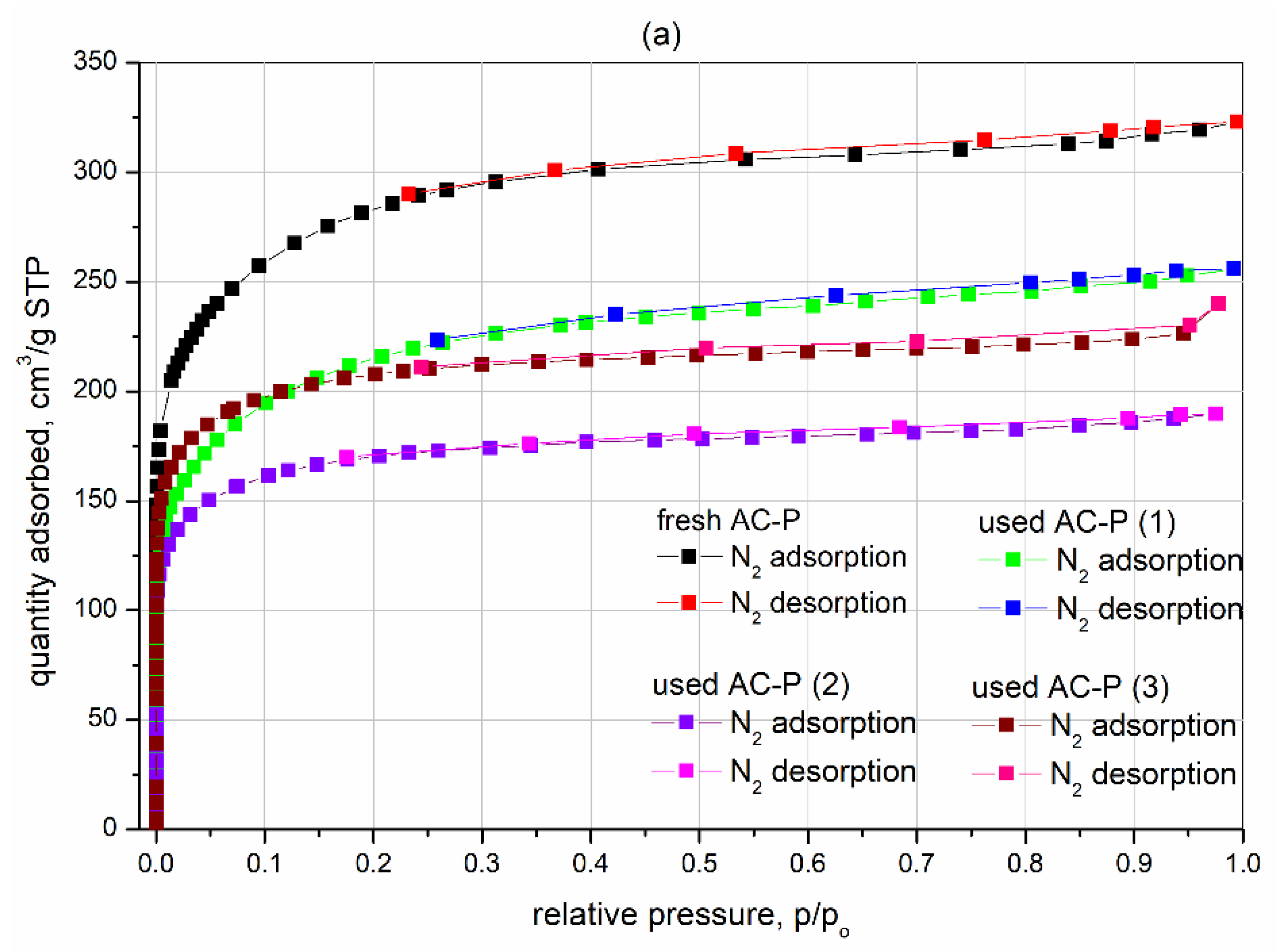
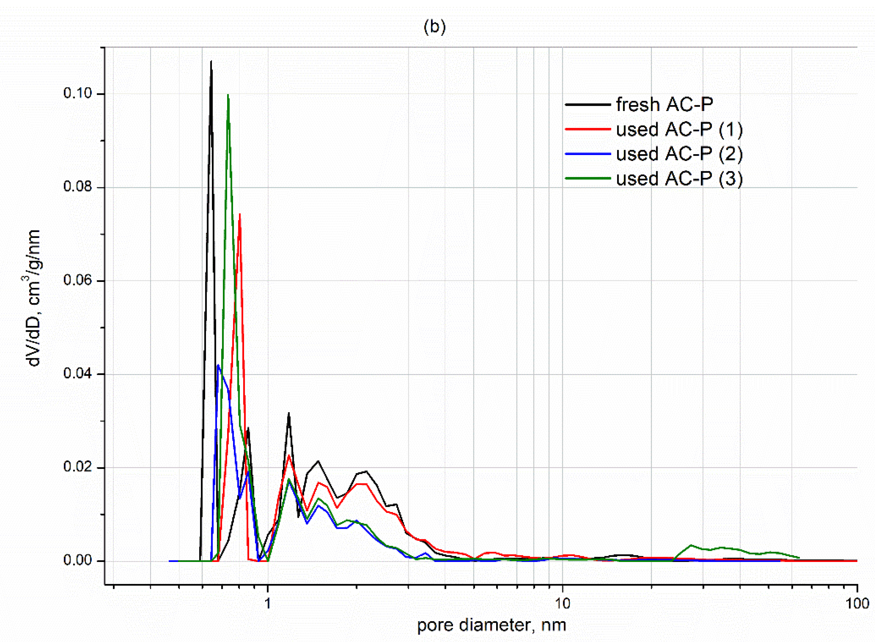
Sulfur presence was also confirmed by analyzing the chemical composition of the samples (Table 1). Figure 4 presents the nitrogen adsorption–desorption isotherms (Figure 4a) and pore-size distributions (Figure 4b) for the activated carbon AC-P samples before and after use in the deSOx and deNOx adsorber. The adsorption/desorption isotherm of fresh AC-P was a type I isotherm, which confirmed the adsorbent’s microporosity with a large number of mesopores, as demonstrated by the hysteresis loop starting at relative pressure (p/p0) over 0.35. The adsorption/desorption isotherms of the used AC-P presented the same shapes, and differences in relation to fresh AC-P mainly applied to the volume of adsorbed nitrogen (Figure 4a).
This was demonstrated by the behavior of the porous structures of the used AC-P samples after 808 h of use in the desulfurization unit. As shown in Figure 4b, minor changes can also be observed in the pore-size distributions for the activated carbon AC-P samples, both fresh and used. This confirms the presence of minor changes in the porous structures of the AC samples after 808 h of using them to remove sulfur and nitrogen from flue gas before delivering the gas to the adsorption installation for CO2 separation.
3.3. Microstructure of the Spent Activated Carbon
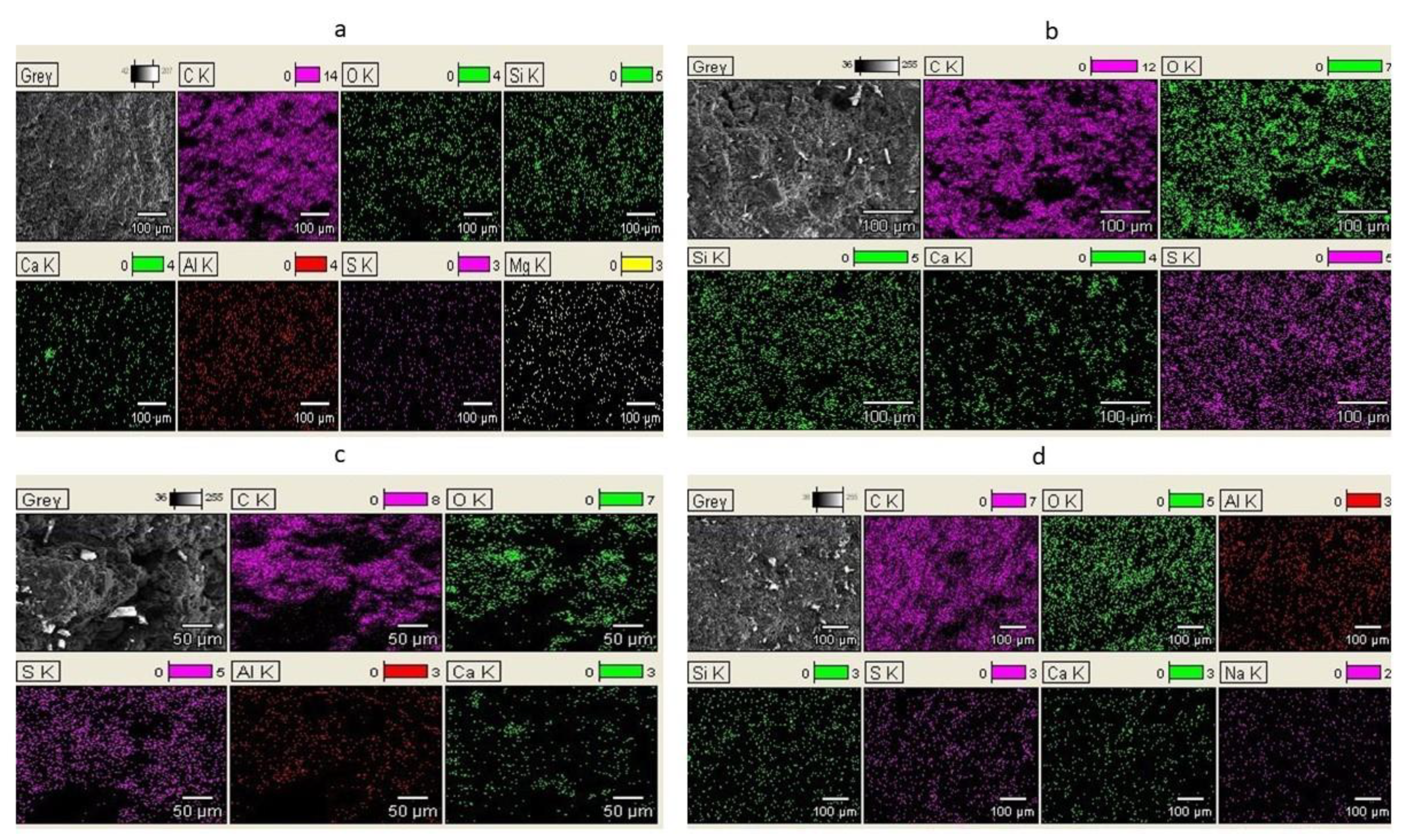
The presence of sulfur in the spent activated carbon AC-P was confirmed by SEM-EDX analysis, according to which the sulfur content was a maximum of 14.0 wt.% for used AC-P (3) retrieved from the adsorber top, 14.92 wt.% for used AC-P (2) retrieved from the adsorber middle, and 20.29 wt. % for used AC-P (1) from the adsorber bottom.
Figure 5 shows SEM photographs and the results of the SEM-EDX chemical constitution analysis on the surface of the impregnated activated carbon (both fresh and used) in the deSOx and deNOx adsorber. The observation of the microstructure in the tested AC-P samples confirmed the occurrence of new structures as a result of the use of the samples in the adsorber. Photographs of the spent AC-P showed crystals of sulfate and potassium sulfite formed as a result of SO2 sorption. Most of the K2SO4 crystals were formed in the bottom of the desulfurization unit (used AC-P (1)), as demonstrated by the SEM photographs (Figure 5b) showing the greatest amount of potassium sulfate crystals. This result was also confirmed by analyzing the chemical composition on the surfaces of the activated carbons, which showed higher sulfur and potassium (K2SO3 and K2SO4) content compared to fresh AC-P in the AC-P samples retrieved after 808 h of use in the adsorber.
3.4. Surface Chemistry of the Spent Activated Carbon
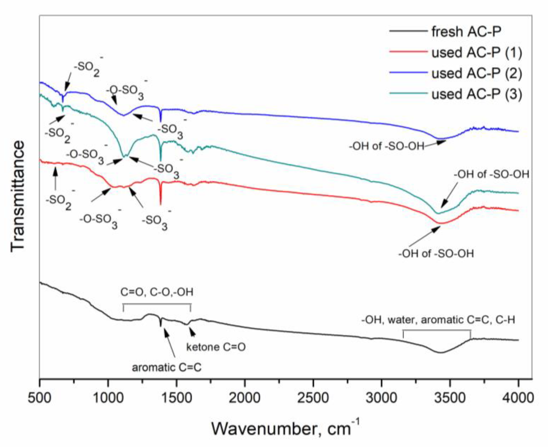
Characterization of the FTIR spectra for sample surface chemistry was carried out to obtain information on changes in the functional groups on the AC-P surface before and after desulfurization and denitrification. Analysis of the FTIR spectra for fresh AC-P and AC-P after use in the adsorber, as presented in Figure 6, confirmed surface changes in the used AC-P due to SO2 adsorption.
No observed changes indicated NOx adsorption. The fresh and used AC-P spectra showed characteristic peaks related to -OH vibrations at 1650 cm−1 and 3500 cm−1 due to the presence of the basic group -OH (originating from KOH and moisture). Moreover, at the 1800–1690 cm−1 wavelength, we observed a peak generated by the ketone group C=O and at 1630 cm−1 from the aromatic group C=C. Below 1600 cm−1, we observed low-intensity peaks from the C=O, C-O, and -OH groups. Extra peaks appeared in the spectra of all used AC-P samples retrieved from the deSOx and deNOx adsorber, which confirmed changes on the surfaces of the spent activated carbons. The signals at 1150 cm−1 could be linked to sulfates generated after SO2 adsorption (the strong band/spectrum of the -OH group belonging to the -SO-OH group was generated during SO2 adsorption on the AC-P at 3435 cm−1, the band at 1159 cm−1 originated from the –SO3- group, and the strong band at 1113 cm−1 originated from the -O-SO3- group) [28]. During the analysis of SO2 adsorption on activated carbon with potassium hydroxide activation, many of the same groups were observed by Lee et al. [28]. No groups indicating the formation of nitrates were found on the surface of the used AC-P. Moreover, a weak band of the -SO2- group appeared at 984 cm−1. However, as emphasized by other authors [28], low-intensity peaks that induce microscopic changes via functional groups generated through SO2 adsorption might become hidden or overlap and thus would not be observed. To sum up, during SO2 adsorption, activated carbon impregnated with KOH works as a selective site of adsorption, with the OH- groups guaranteeing basic atmosphere and K+ ions facilitating stable SO2 adsorption on carbon. Due to potassium, the chemicals created on the surface during adsorption include stable ionic crystals such as K2SO3 and K2SO4. This is because potassium is highly reactive and cannot exist as a single element; instead, potassium exists in chemical compounds [28]. Previous studies on the properties of carbon surfaces after SO2 adsorption indicate that strong chemical interactions between KOH and SO2 largely depend on the impregnated carbon’s surface chemistry.
3.5. Stability of the Spent Activated Carbon
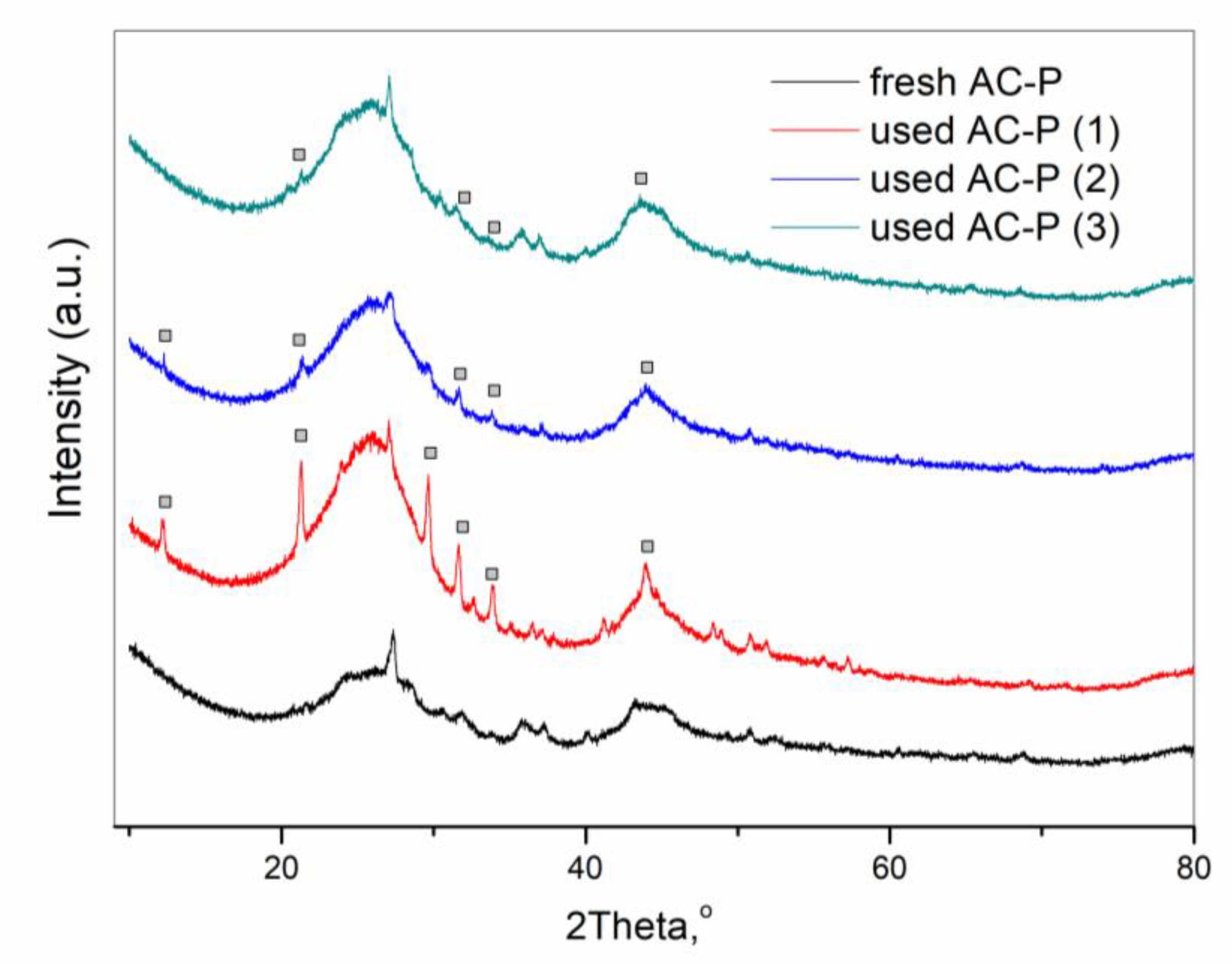
Based on the information for the surface functional groups obtained from the FTIR analysis, the presence of adsorbed substances on the used AC-P was also examined using XRD analysis. The XRD analysis allowed us to identify the substances formed on the surface of the activated carbon after SO2 adsorption. Figure 7 shows the XRD spectra for fresh and used AC-P. For fresh AC-P, a high-intensity peak (2Ɵ = 26.5) was observed. This peak was not seen on any of the used AC-Ps. This peak may indicate the presence of potassium and basic OH ions (AC impregnated with KOH) on the external surface of fresh AC-P that disappeared after SO2 adsorption. The XRD spectra of all the used AC-Ps indicated the presence of K2SO4 generated as a result of a reaction between sulfur oxides and potassium hydroxide (high-intensity peak at 2Ɵ = 30.7), whereas high-intensity peaks at 2Ɵ = 21.24, 29.7, 30.74, and 43.36 as well as small intensity peaks at 35.8 and 37.04 were observed in all the samples after SO2 adsorption.
Figure 8a,b shows the TG and DTG curves of activated carbon (fresh AC-P and AC-P after use in the deSOx and deNOx adsorber) under an inert atmosphere (N2). As shown in Figure 8a, each sample was characterized by varying the mass loss during the experiment. The greatest mass loss was observed for activated carbon with AC-P (1) after use in the deSOx and deNOx adsorber. The loss amounted to 35%, whereas fresh AC-P’s mass loss was 20%. As indicated by the TG/DTG curves (Figure 8a,b), two types of mass loss were observed in the fresh AC-P sample. The first type of mass loss was due to the desorption of physically adsorbed water. The second type of mass loss (200–1000 °C) resulted from the slow thermal decomposition of the surface functional groups with low stability and the least thermally stable carbon structure.
Different situations were observed for all spent AC-P-activated carbon. As indicated by the TG/DTG curves (Figure 8a,b), four types of mass loss were observed in the spent AC-P samples. The first type of mass loss (30–200 °C) was due to the desorption of surface water. The second type of mass loss (200–400 °C) resulted from the removal of water from the pores of the adsorbent. The third type of mass loss (440–650 °C) was due to the desorption of sulfur. The fourth type of mass loss (>650 °C) resulted from the decomposition of potassium sulfate. All completed analyses demonstrated that the mechanism of deep flue gas purification on the activated carbon using AC-P involved the reaction of SO2 to K2SO3 and, through oxidation of SO2 to SO3 and adsorption, a reaction to K2SO4. The presence of these compounds was confirmed by XRD, SEM-EDX, and TG analyses. However, the presence of nitrogen oxide removal products was not observed, indicating that nitrogen oxides, especially NO, were not oxidized in the desulfurization unit to N2O5 and N2O4 and thus did not react with KOH to produce potassium nitrites and nitrates (KNO2, KNO3). The FTIR, XRD, SEM-EDX, and TG analyses also did not confirm the existence of these compounds. A previous study carried out by the present authors also confirmed that NOx was not removed from flue gas before CO2 adsorption in a special section [9]. According to these studies, a large part of the NOx was adsorbed—not in the desulfurization and NOx removal section, but in the CO2 separation section, thus contaminating the activated carbon. The used activated carbon materials (in the four adsorption columns—CO2 separation section) featured increased nitrogen content, which suggested the slight adsorption of NOx captured from the flue gas. Details of this analysis can be found in [9]. Many of the same results were obtained by Lee et al. [29] during a study on the surface of impregnated activated carbon after NOx and SO2 adsorption. The authors observed that in most cases, adsorption proceeded during chemical reactions. Due to the presence of OH groups on the surface, the KOH-impregnated activated carbon oxidized due to NOx and SO2 adsorption. In particular, SO2 presented strong interactions with KOH-impregnated activated carbon, forming K2SO4 on the external surface of activated carbon. Lee et al. [29] also observed that more SO2 adsorbed on the surface of KOH-impregnated activated carbon corresponded to less NOx being adsorbed. The authors in [29] showed that the individual adsorption of NOx and SO2 proceeded differently than the simultaneous adsorption of both impurities. Many of the same conclusions were presented by Abdulrasheed et al. [27], who observed that the simultaneous removal of NOx and SO2 using KOH-impregnated activated carbon in an environment rich in O2 showed SO2 to have higher affinity to the adsorbent than NOx. This was likely also the case in our research. On the other hand, when these gases were removed separately, NOx showed higher affinity than SO2. The stronger affinity of SO2 ensured a higher rate of chemisorption on the surface of impregnated activated carbon and the bonding of oxygen groups (needed for NO oxidation and further NO2 adsorption on activated carbon), especially in the presence of moisture and sulfuric acid formation. The conducted research shows that the practical use of technology involving the simultaneous removal of both SO2 and NOx still makes flue gas desulfurization and denitrification challenging and requires significant research in this area. This result was also confirmed by the study of Neathery et al. [30] on selective NOx capture from flue gas containing SO2, CO2, H2O, O2, and N2. Neathery et al. observed that NOx can be selectively adsorbed from flue gas mixtures, but only under the proper conditions—i.e., a sufficiently high oxygen concentration, low SO2 concentration, and a proper temperature range of 35–120 °C. This suggests that under our real research conditions on simultaneous SO2 and NOx adsorption from flue gas, the above conditions were not met, leading NOx adsorption to be minimal. The conclusions of the study highlight that the simultaneous removal of both SO2 and NOx from real CFB flue gas on impregnated activated carbon is still challenging and dependent on the particular conditions of the flue gas.
3.6. Analysis of Flue Gas Constitution before and after Leaving the Adsorber
Information obtained based on analysis of the physicochemical properties of AC-P before and after use in the deSOx and deNOx adsorber was also confirmed by analyzing the flue gas constitution before and after leaving the adsorber (marked as points 1 and 2 in Figure 2). Figure 9a shows that before entering the adsorber, almost all the SO2 contained in the flue gas was captured via impregnated AC-P, and the volume of SO2 in flue gas leaving the adsorber did not exceed 5 mg/Nm3 (SO2 content at the adsorber inlet was 1–111 mg/Nm3).
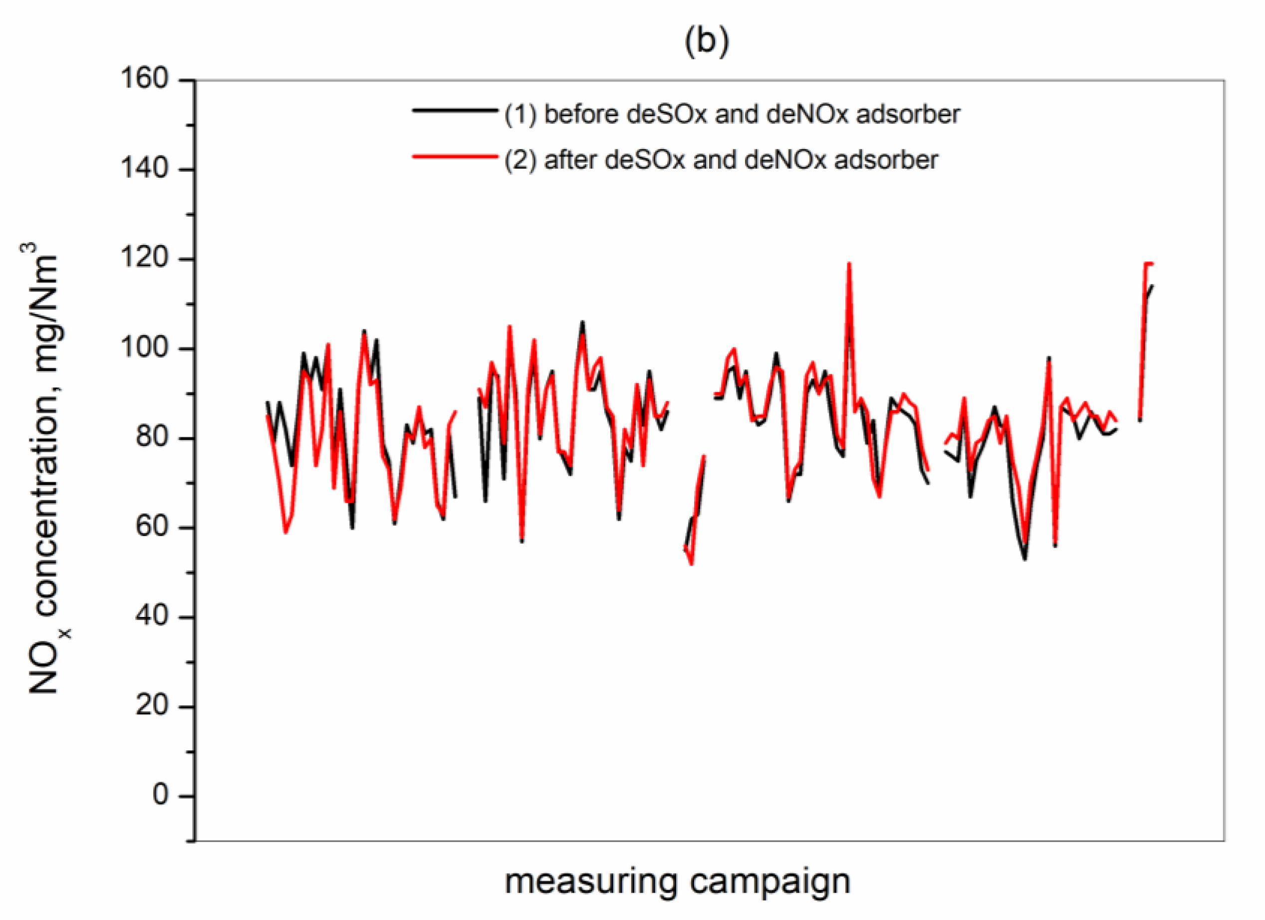
This result confirmed the efficacy of desulfurization in the deSOx and deNOx adsorber. The total SOx removal efficiency amounted to 95.5–100%. Similar results were reported by Ishibashi et al. [4,5]. In [4,5], SO2 removal was so effective that no SO2 accumulation was observed in the CO2 adsorbent removed after 2000 h of use in a PTSA/PSA adsorption installation for CO2 capture. The authors also stated that for CO2 capture VPSA processes, installing a SOx desulfurization and NOx removal section was less expensive than accepting the adsorbent degradation when the flue gas contained more than 10 mg/Nm3 SO2 and 10 mg/Nm3 NOx [4,5]. Our analysis of the adsorbent also confirmed the effective removal of SO2 in the pre-treatment section. Replacement of the AC-P sorbent that filled the deSOx/deNOx adsorber was not necessary after 808 h of DR-VPSA operation because no increase in the SO2 concentration at the outlet of the column was observed. This result confirmed the effectiveness and lifespan of the adsorbent used to remove SO2. However, the situation was different for nitrogen oxides, which were not captured in the adsorber, as shown in Figure 9b. The content of nitrogen oxides in the flue gas (reaching 55–120 mg/Nm3 before entering the adsorber) dropped by only a few mg/Nm3 after leaving the adsorber. However, it never exceeded 120 mg/Nm3. In a previous study completed by the same authors of the present work [9], uncaptured NOx progressed to the CO2 separation section (DR-VPSA), where it was adsorbed on the CO2 adsorbent and as a result of cyclic sorption/desorption processes, mixed with recirculating gas and ultimately appeared as impurities in the final CO2 product [8]. This result confirmed that the process of removing NOx in desulfurization and the NOx removal section was ineffective.
4. Conclusions
The present results based on real CFB flue gas at the Lagisza Power Plant demonstrated that using AC impregnated with KOH and KJ in the adsorber to remove sulfur and nitrogen oxides in the pre-treatment module of the adsorption CO2 capture unit (DR-VPSA) was a solution that ensured sufficient flue gas purification and the removal of sulfur oxides. However, this method is insufficient for nitrogen oxides. The impregnated activated carbon showed adequate sorptive properties and proper thermal stability. It also did not change its properties during prolonged use in the adsorber. The tested activated carbon allowed for the effective removal of sulfur oxides under the continuous operation of the DR-VPSA installation for variable SO2 and NOx loading in real flue gas conditions. This was confirmed by completed analyses of the spent activated carbon, which allowed finding the presence of SO2 adsorption products with chemical reaction, as potassium sulfate, on the surface of the spent activated carbon. From among the various alternatives, the removal of impurities from the flue gas through adsorption on surface-modified KOH/KJ activated carbon proved to be an efficient and reliable technology for sulfur oxides. However, the removal of nitrogen oxides under real conditions was not assessed.
Author Contributions
Conceptualization, I.M.-K.; investigation, I.M.-K., D.W., A.Z., J.Z., and W.S.; methodology, I.M.-K.; writing—original draft preparation, I.M.-K.; writing—review and editing, I.M.-K. and D.W. All authors have read and agreed to the published version of the manuscript.
Funding
The funds for covering the costs to publish with open access were provided by the statute subvention of Czestochowa University of Technology, Faculty of Infrastructure and Environment.
Institutional Review Board Statement
Not applicable.
Informed Consent Statement
Not applicable.
Data Availability Statement
Not applicable.
Acknowledgments
The authors are thankful to the stuff from Lagisza Power Plant for valuable support during the long-term field tests. The results presented in this paper were obtained from research work co-financed by the National Centre of Research and Development in the framework of Contract SP/E/1/67484/10—Strategic Research Program—Advanced technologies for obtaining energy: Development of a technology for highly efficient zero-emission coal-fired power units integrated with CO2 capture. This article has been supported by the Polish National Agency for Academic Exchange under Grant No PPI/APM/2019/1/00042.
Conflicts of Interest
The authors declare no conflict of interest.
References
- Bhown, A.B.; Freeman, B.C. Analysis and Status of Post-Combustion Carbon Dioxide, Capture Technologies. Environ. Sci. Technol. 2011, 45, 8624–8632. [Google Scholar] [CrossRef]
- International Energy Agency. Carbon Capture, Utilization and Storage, a Critical Tool in the Climate Energy Toolbox. Available online: https://www.iea.org/topics/carbon-capture-and-storage/ (accessed on 25 February 2021).
- Webley, P.A. Adsorption technology for CO2 separation and capture: A perspective. Adsorption 2014, 20, 225–231. [Google Scholar] [CrossRef]
- Ishibashi, M.; Ota, H.; Akutsu, N.; Umeda, S.; Tajika, M.; Izumi, J.; Yasutake, A.; Kabata, T.; Kageyama, Y. Technology for removing carbon dioxide from power plant flue gas by the physical adsorption method. Energy Convers. Manag. 1996, 37, 929–933. [Google Scholar] [CrossRef]
- Ishibashi, M.; Otake, K.; Kanamori, S.; Yasutake, A. Study on CO2 removal technology from flue gas of thermal power plant by physical adsorption method. In Greenhouse Gas Control Technologies, Proceedings of the 4th International Conference, Interlaken, Switzerland, 30 August–2 September 1998; Eliasson, B., Riemer, P., Wokaun, A., Eds.; Elsevier Science Ltd.: Oxford, UK, 1998; pp. 131–136. [Google Scholar]
- Wang, L.; Yang, Y.; Shen, W.; Kong, X.; Li, P.; Yu, J.; Rodrigues, A.E. CO2 capture from flue gas in an existing coal-fired power plant by two successive pilot-scale VPSA units. Ind. Eng. Chem. Res. 2013, 52, 7947–7955. [Google Scholar] [CrossRef]
- Qader, A.; Hoopera, B.; Innocenzib, T.; Stevensc, G.; Kentishc, S.; Scholesc, C.; Mumfordc, K.; Smithc, K.; Webley, P.A.; Zhangd, J. Novel post-combustion capture technologies on a lignite fired power plant-results of the CO2CRC/H3 capture project. Energy Procedia 2011, 4, 1668–1675. [Google Scholar] [CrossRef] [Green Version]
- Wawrzyńczak, D.; Majchrzak-Kucęba, I.; Srokosz, K.; Kozak, M.; Nowak, W.; Zdeb, J.; Smółka, W.; Zajchowski, A. The pilot dual-reflux vacuum pressure swing adsorption unit for CO2 capture from flue gas. Sep. Purif. Technol. 2019, 209, 560–570. [Google Scholar] [CrossRef]
- Majchrzak-Kucęba, I.; Wawrzyńczak, D.; Ściubidło, A.; Zdeb, J.; Smółka, W.; Zajchowski, A. Stability and regenerability of acivated carbon used for CO2 removal in pilot DR-VPSA unit in real power plant conditions. J. CO₂ Util. 2019, 29, 1–11. [Google Scholar] [CrossRef]
- Chapel, D.G.; Ernest, J.; Mariz, C.L. Recovery of CO2 from Flue Gases: Commercial Trends. In Proceedings of the Canadian Society of Chemical Engineers annual meeting, Saskatoon, SK, Canada, 4–6 October 1999. [Google Scholar]
- Hu, J.; Liu, Y.; Liu, J.; Gu, C. Effects of water vapor and trace gas impurities in flue gas on CO2 capture in zeolitic imidazolate frameworks: The significant role of functional groups. Fuel 2017, 200, 244–251. [Google Scholar] [CrossRef]
- Schallert, B.; Satterley, C.; Neuhaus, S. The impact of NO2 on post-combustion capture: What concentration of NO2 is expected in front of the absorber and what is its fate in the capture proces? In Proceedings of the 2nd Post Combustion Capture Conference (PCCC2), Bergen, Norway, 7–20 September 2013. [Google Scholar]
- Zhang, J.; Xiao, P.; Li, G.; Webley, P.A. Effect of Flue gas impurities on CO2 capture performance from flue gas at coal-fired power stations by Vacuum Swing adsorption. Energy Procedia 2009, 1, 115–1122. [Google Scholar] [CrossRef] [Green Version]
- Sayari, A.; Belmabkhout, Y.; Serna-Guerrero, R. Flue gas treatment via CO2 adsorption. Chem. Eng. J. 2011, 171, 760–774. [Google Scholar] [CrossRef]
- Sass, B.; Ricci, S.; Gupta, A.; Hindin, B.; Gupta, N. Impact od SOx and NOx in flue gas on CO2 separation, compression and pipeline transmission. In Carbon Dioxide Capture and Storage in Deep Geologic Formations—Results from the CO2 Capture Project; Thomas, D.C., Ed.; Elsevier: Amsterdam, The Netherlands, 2005; pp. 955–981. [Google Scholar]
- Porter, R.T.J.; Fairwether, M.; Pourkashanian, M. The range and level of impurities in CO2 streams from different carbon capture sources. Int. J. Greenh. Gas Control. 2015, 36, 161–174. [Google Scholar] [CrossRef]
- Cao, A.; Zhao, H.; Hu, D.; Wang, J.; Li, M.; Zhou, Z.; Shen, Q.; Sun, N.; Wei, W. Preparation of potassium intercalated carbons by in-situ activation and speciation for CO2 capture from flue gas. J. CO2 Util. 2020, 35, 59–66. [Google Scholar] [CrossRef]
- Labus, K.; Grygiewicz, K.; Machnikowski, J. Granular KOH-activated carbons from coal-based cokes and their CO2 adsorption capacity. Fuel 2014, 118, 9–15. [Google Scholar] [CrossRef]
- Li, D.; Zhou, J.; Wang, Y.; Tian, Y.; Wei, L.; Zhang, Z.; Qiao, Y.; Li, J. Effects of activation temperature on densities and volumetric CO2 adsorption performance of alkali-activated carbons. Fuel 2019, 238, 232–239. [Google Scholar] [CrossRef]
- Sabouni, R.; Kazemian, H.; Rohani, S. Carbon dioxide capturing technologies: A review focusing on metal organic framework materials (MOFs). Environ. Sci. Pollut. Res. 2014, 21, 5427–5449. [Google Scholar] [CrossRef] [PubMed]
- Gargiulo, V.; Alfe, M.; Raganati, F.; Lisi, L.; Chirone, R.; Ammendola, P. BTC-based metal-organic frameworks: Correlation between relevant structural features and CO2 adsorption performances. Fuel 2018, 222, 319–326. [Google Scholar] [CrossRef]
- Zelenak, V.; Halamowa, D.; Gaberowa, L.; Bloch, E.; Lewellyn, P. Amine-modified SBA-12 mesoporous silica for carbon dioxide capture: Effect of amine basicity on sorption properties. Micropor. Mesopor. Mater 2008, 116, 358–364. [Google Scholar] [CrossRef]
- Wappel, D.; Khan, A.; Shallcross, D.; Joswig, S.; Kentish, S.; Stevens, G. The effect of SO2 on CO2 absorption in an aqueous potassium carbonate solvent. Energy Procedia 2009, 1, 125–131. [Google Scholar] [CrossRef] [Green Version]
- Directive 2010/75/EU of the European Parliament and the Council on Industrial Emissions (the Industrial Emissions Directive or IED). Available online: http://data.europa.eu/eli/dir/2010/75/oj (accessed on 20 February 2021).
- Guo, Y.; Li, Y.; Zhu, T.; Ye, M. Investigation of SO2 and NO adsorption species on activated carbon and the mechanism of NO promotion effect on SO2. Fuel 2015, 143, 536–542. [Google Scholar] [CrossRef]
- Qiang, T.; Zhigang, Z.; Wenpei, Z.; Zidong, C. SO2 and NO selective adsorption properties of coal-based activated carbons. Fuel 2005, 84, 461–465. [Google Scholar] [CrossRef]
- Abdulrasheed, A.A.; Jalil, A.A.; Triwahyono, S.; Zaini, M.A.A.; Gambo, Y.; Ibrahim, M. Surface modification of activated carbon for adsorption of SO2 and NOx: A review of existing and emerging technologies. Renew. Sustain. Energy Rev. 2018, 94, 1067–1085. [Google Scholar] [CrossRef]
- Lee, Y.W.; Park, J.W.; Choung, J.H.; Choi, D.K. Adsorption Characteristics of SO2 on Activated Carbon Prepared from Coconut Shell with Potassium Hydroxide Activation. Environ. Sci. Technol. 2002, 36, 1086–1092. [Google Scholar] [CrossRef]
- Lee, Y.W.; Kim, H.J.; Park, J.W.; Choi, B.U.; Choi, D.K. Adsorption and reaction behaviour for the simultaneous adsorption of NO–NO2 and SO2 on activated carbon impregnated with KOH. Carbon 2003, 41, 1881–1888. [Google Scholar] [CrossRef]
- Neathery, J.K.; Rubel, A.M.; Stencel, J.M. Uptake of NOx by activated carbons: Bench-scale and pilot-plant testing. Carbon 1997, 35, 1321–1327. [Google Scholar] [CrossRef]
Figure 1.
Pre-treatment sections in global pilot adsorption CO2 capture units (PTSA: pressure temperature swing adsorption; PSA: pressure swing adsorption; VSA: vacuum swing adsorption; VPSA: vacuum pressure swing adsorption; DR-VPSA: dual-reflux vacuum pressure swing adsorption).
Figure 1.
Pre-treatment sections in global pilot adsorption CO2 capture units (PTSA: pressure temperature swing adsorption; PSA: pressure swing adsorption; VSA: vacuum swing adsorption; VPSA: vacuum pressure swing adsorption; DR-VPSA: dual-reflux vacuum pressure swing adsorption).

Figure 2.
The scheme of the pilot DR-VPSA unit including the locations of the AC sample retrieval for analysis purposes (1, 2: flue gas drawing locations).
Figure 2.
The scheme of the pilot DR-VPSA unit including the locations of the AC sample retrieval for analysis purposes (1, 2: flue gas drawing locations).

Figure 3.
Retrieval locations for the activated carbon AC-P used as packing for the deSOx and deNOx adsorber in the pilot DR-VPSA CO2 capture unit.
Figure 3.
Retrieval locations for the activated carbon AC-P used as packing for the deSOx and deNOx adsorber in the pilot DR-VPSA CO2 capture unit.

Figure 4.
Nitrogen adsorption–desorption isotherms (a) and pore-size distributions (b) for activated carbon samples: fresh AC-P, used AC-P (1), used AC-P (2), and used AC-P (3).
Figure 4.
Nitrogen adsorption–desorption isotherms (a) and pore-size distributions (b) for activated carbon samples: fresh AC-P, used AC-P (1), used AC-P (2), and used AC-P (3).


Figure 5.
SEM-EDX analysis of activated carbon (fresh and used) in the deSOx and deNOx adsorber: (a) AC-P; (b) used AC-P (1); (c) used AC-P (2) and (d) used AC-P (3).
Figure 5.
SEM-EDX analysis of activated carbon (fresh and used) in the deSOx and deNOx adsorber: (a) AC-P; (b) used AC-P (1); (c) used AC-P (2) and (d) used AC-P (3).

Figure 6.
FTIR profiles of impregnated activated carbon: fresh and after use in the deSOx and deNOx adsorber: fresh AC-P, used AC-P (1), used AC-P (2), and used AC-P (3).
Figure 6.
FTIR profiles of impregnated activated carbon: fresh and after use in the deSOx and deNOx adsorber: fresh AC-P, used AC-P (1), used AC-P (2), and used AC-P (3).

Figure 7.
The XRD spectra of activated carbon (fresh and after use in the deSOx and deNOx adsorber): fresh AC-P, used AC-P (1), used AC-P (2) and used AC-P (3).
Figure 7.
The XRD spectra of activated carbon (fresh and after use in the deSOx and deNOx adsorber): fresh AC-P, used AC-P (1), used AC-P (2) and used AC-P (3).

Figure 8.
TG (a) and DTG (b) curves of activated carbon (fresh and after use in the deSOx and deNOx adsorber): fresh AC-P, used AC-P (1), used AC-P (2), and used AC-P (3).
Figure 8.
TG (a) and DTG (b) curves of activated carbon (fresh and after use in the deSOx and deNOx adsorber): fresh AC-P, used AC-P (1), used AC-P (2), and used AC-P (3).


Figure 9.
Online analysis of SO2 concentration (a) and NOx concentration (b) in the flue gas before and after leaving the deSOx and deNOx adsorber (the temperature of the CFB flue gas was 25 °C, the maximum capacity of the DR-VPSA installation was 100 Nm3/h, the measuring campaign was 808 h).
Figure 9.
Online analysis of SO2 concentration (a) and NOx concentration (b) in the flue gas before and after leaving the deSOx and deNOx adsorber (the temperature of the CFB flue gas was 25 °C, the maximum capacity of the DR-VPSA installation was 100 Nm3/h, the measuring campaign was 808 h).


Table 1.
The elemental composition of the fresh and used activated carbon AC-P.
| Adsorbent | Elemental Composition | ||||
|---|---|---|---|---|---|
| C, wt.% | H, wt.% | N, wt.% | S, wt.% | Other, O wt.% | |
| fresh AC-P | 72.34 | 1.80 | 0.86 | 0.29 | 24.71 |
| used AC-P (1)—bottom | 63.16 | 2.66 | 0.67 | 4.14 | 29.37 |
| used AC-P (2)—middle | 66.81 | 2.56 | 0.53 | 2.75 | 27.35 |
| used AC-P (3)—top | 69.86 | 2.44 | 0.73 | 0.98 | 25.99 |
Table 2.
Porous properties of the fresh and used impregnated activated carbon AC-P.
| Sample | Textural Properties | ||
|---|---|---|---|
| BET Surface Area, m2 g−1 | Total Pore Volume, cm3 g−1 | Total Pore Area, m2 g−1 | |
| fresh AC-P | 959.00 | 0.41 | 739.30 |
| used AC-P (1)—bottom | 555.20 | 0.23 | 459.03 |
| used AC-P (2)—middle | 692.13 | 0.31 | 572.67 |
| used AC-P (3)—top | 736.46 | 0.33 | 515.95 |
Publisher’s Note: MDPI stays neutral with regard to jurisdictional claims in published maps and institutional affiliations. |
© 2021 by the authors. Licensee MDPI, Basel, Switzerland. This article is an open access article distributed under the terms and conditions of the Creative Commons Attribution (CC BY) license (https://creativecommons.org/licenses/by/4.0/).
Share and Cite
MDPI and ACS Style
Majchrzak-Kucęba, I.; Wawrzyńczak, D.; Zdeb, J.; Smółka, W.; Zajchowski, A. Treatment of Flue Gas in a CO2 Capture Pilot Plant for a Commercial CFB Boiler. Energies 2021, 14, 2458. https://0-doi-org.brum.beds.ac.uk/10.3390/en14092458
AMA Style
Majchrzak-Kucęba I, Wawrzyńczak D, Zdeb J, Smółka W, Zajchowski A. Treatment of Flue Gas in a CO2 Capture Pilot Plant for a Commercial CFB Boiler. Energies. 2021; 14(9):2458. https://0-doi-org.brum.beds.ac.uk/10.3390/en14092458
Chicago/Turabian StyleMajchrzak-Kucęba, Izabela, Dariusz Wawrzyńczak, Janusz Zdeb, Wojciech Smółka, and Artur Zajchowski. 2021. "Treatment of Flue Gas in a CO2 Capture Pilot Plant for a Commercial CFB Boiler" Energies 14, no. 9: 2458. https://0-doi-org.brum.beds.ac.uk/10.3390/en14092458
Note that from the first issue of 2016, this journal uses article numbers instead of page numbers. See further details here.