
Using Heat Pumps to Improve the Efficiency of Combined-Cycle Gas Turbines


Higher School of Nuclear and Heat Power Engineering, Institute of Energy, Peter the Great St. Petersburg Polytechnic University, 195251 St. Petersburg, Russia
*
Author to whom correspondence should be addressed.
Energies 2021, 14(9), 2685; https://0-doi-org.brum.beds.ac.uk/10.3390/en14092685
Submission received: 14 March 2021
/
Revised: 26 April 2021
/
Accepted: 4 May 2021
/
Published: 7 May 2021
(This article belongs to the Special Issue Refrigeration, Air Conditioning and Heat Pumps: Energy and Environmental Issues II)
Abstract
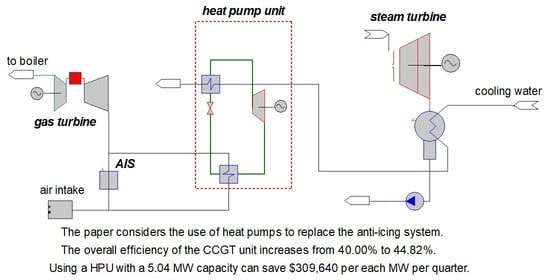
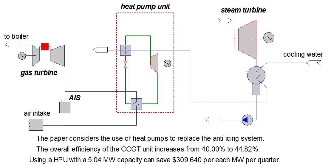
:This paper studies the integration of heat pump units (HPUs) to enhance the thermal efficiency of a combined heat and power plant (CHPP). Different solutions of integrate the HPUs in a combined-cycle gas turbine (CCGT) plant, the CCGT-450, are analyzed based on simulations developed on “United Cycle” computer-aided design (CAD) system. The HPUs are used to explore low-potential heat sources (LPHSs) and heat make-up and return network water. The use of HPUs to regulate the gas turbine (GT) intake air temperature during the summer operation and the possibility of using a HPU to heat the GT intake air and replace anti-icing system (AIS), over the winter at high humidity conditions were also analyzed. The best solution was obtained for the winter operation mode replacing the AIS by a HPU. The simulation results indicated that this scheme can reduce the underproduction of electricity generation by the CCGT unit up to 14.87% and enhance the overall efficiency from 40.00% to 44.82%. Using a HPU with a 5.04 MW capacity can save $309,640 per each MW per quarter.
1. Introduction
The limited amount of fuel sources and the constantly enhancing needs in electricity stimulated the developing of production of electrical and heat energy by means of combined-cycle gas turbine (CCGT) combined heat and power plants (CHPPs). This is due to the fact that the combined production of electricity and heat at CCGT-CHPPs is more efficient than the separate production of electricity at condensing thermal power plants and the production of heat by boilers [1]. Because of that, for example, over the past 15 years, more than 40 powerful combined-cycle power units have been installed in the Russian Federation. The process of production of electrical and heat energy at combined-cycle gas turbine combined heat and power plants, being a technological process, generates a certain amount of secondary heat sources [2]. This makes it possible to declare it necessary to increase their efficiency.
Currently, a large number of studies are devoted to finding new ways to optimize the operation of CCGT units. E. Godoy et al. [3] considered the possibility of thermodynamic optimization of the CCGT unit. This makes it possible to increase the efficiency of the CCGT unit even at the design stage. The results are useful in the preliminary stages of design of a process plant, allowing trends in the system behavior to be identified and revealing optimization opportunities [3].
The research of E. Pihl [4] studied options for biomass thermal conversion, for power production, integrated with existing CCGT power plants. A hybrid combined cycle concept where biomass is used in the bottoming cycle can increase efficiency. Also, efficiency increases can be found for gasification of biomass, where the syngas is used as a supplement for natural gas in the CCGT [4].
The work of T. Leo [5] can serve as an interesting example of optimizing the work and increasing the efficiency of a CCGT unit. In her work, it was proposed to drive a compressor using a steam turbine as part of a CCGT. This solution allows a gas turbine to generate more electricity. Also, compressed air between two compressor cylinders was cooled in a heat exchanger by a steam turbine condensate. By cooling the gas turbine (GT) air and heating condensate at the intake of the waste heat boiler, it is possible to increase power generated by both turbines gas and steam.
In the field of research related to improving the characteristics of CCGT units, ideas of controlling a temperature of the air entering a combustion chamber of a GT are popular. A gas turbine intake air temperature is directly related to the ambient air temperature. Among all variables that can influence the operation of a CCGT, the ambient temperature causes the greatest performance variation during operation [6].
As is known, it makes sense to preheat the air before a combustion chamber of a gas turbine in order to save fuel. A simple example of this is the use of a gas turbine flue gas regenerator. Using such a heat exchanger, in his work A. Colmenar-Santos obtained an increase in the efficiency of a gas turbine as part of a CCGT unit up to 3.3% [7].
In areas rich in solar energy, it is possible to heat the air by using solar energy. This was demonstrated by D. Olivenza-Leon [8]. This method allowed him to achieve an increase in the supply of electricity by 30% and the efficiency of the gas turbine plant relative to the initial mode by 19%.
D. Mendeleev with his colleagues in [9,10] analyzed the use of an absorption heat pump (AHP) for cooling the intake air before a CCGT. The authors created a mathematical model and selected the type of absorption machine. The possibility of regulating the intake air temperature in summer time and, as result, the increase of a CCGT electricity generation, were highlighted.
In the above articles, additional heating or cooling of the air was carried out before the combustion chamber. However, in addition to regulating the temperature of the air before the combustion chamber in order to save fuel, for some operating modes of the GT there is a need to heat the air directly before the compressor. This is due to the high probability of icing of the equipment required for air purification, as well as the first stages of the compressor in areas with low temperatures and high air humidity. In this paper, the possibility of increasing the efficiency and improving the output characteristics of the CCGT unit is considered in the presence of the threat of icing of the air intake system of a gas turbine.
In order to increase the efficiency of the processes of generating heat and electricity by a CCGT, the option of using heat pump units is being considered. Using heat pumps can provide an enhancement of the energy efficiency of manufacturing, especially in conditions of energy intensity of products [11]. Quantitatively, this can be expressed in a decrease of specific costs of the reference fuel for electricity and heat release [12], as applied to thermal power plants.
In addition, the involvement of consumers of low-potential heat, that is not suitable for the direct use, in the process of the heat release with the help of heat pump units (HPUs) opens up great prospects in terms of energy conservation and rationalization of environmental management both at the level of a particular enterprise and at the general economic level.
In western countries, a decentralized heating system is quite common, as well as the use of non-traditional and renewable energy sources. However, both in the west and in the east, there are works devoted to the use of heat pumps at thermal power plants and of heat pumps in enterprises and manufactures.
A. Alimgazin studied the possibility of integrating heat pumps in order to recover low-grade heat emissions at enterprises. Integration of heat pump units in thermal schemes of manufactures leads to boosting heat generating capacities while not increasing consumption of primary fuel [13]. Also A. Alimgazin suggested some designs of the inclusion of AHPs in such an enterprise [14].
H.S. Zhang et al. analyzed the use of absorption heat pumps integrated in coal-fired combined heat and power (CHP) plants [15]. In the paper, the authors created the mathematical models of the CHP system with an absorption heat pump recovering waste heat of exhausted steam from a steam turbine of a coal-fired direct air-cooling unit. Authors suggested a partial replacing of the heat exchanger of the heating network. H.S. Zhang showed that using AHPs can lead to the total increase of the plant’s thermal efficiency up to 2% and thus reduction in the coal consumption. Thus, a possible and interesting way is using HPUs for heating the return network water.
In another article [16] H.S. Zhang with his colleagues created the model of integrating an AHP into the circuit of a gas-steam combined cycle power plant for heating the return network water. As in [15] the exhaust steam played a role of a low-potential heat source (LPHS) for a heat pump. The increase of the energy efficiency also amounted to 2%.
A. Vannoni’s research work shows that the integration of heat pumps into a combined cycle gas turbine for heating network water can enhance its performances [17]. The chief method used in this research is a modelling. The authors used the flue gas as a source of low-potential heat. The integration of heat pumps totally increases seasonal global efficiency up to 5%.
In the aforementioned works [15,16,17], heating of network water was considered. Network water has a sufficiently high temperature potential, which can negatively affect the performance of a heat pump. Therefore, an interesting objective is the use of heat pumps as part of a thermal circuit of a CCGT-CHPP for heating make-up water of a heating network. Make-up water before heating in the vacuum deaeration system as part of a CCGT unit has a fairly low temperature level (+1 … +20) °C. This makes it possible to achieve a minimum temperature difference between a possible low-grade heat source and a consumer.
Heat pump units have been used in practice abroad for more than half a century [12], but they still have not found wide distribution in Russia because of “conservative” approaches in relation to the heat-and-power supply and the cheapness of energy resources.
Despite all the prospects and advantages of using HPUs in a heating cycle, the question of their influence on the operating modes of equipment and CCGT-CHPP in general requires additional research. For example, there are not actual researches of using heat pumps for regulating a temperature of the air at the intake of CCGT in foreign journals. Research of integration of heat utilization units for enhancing the efficiency of CCGTs in the Russian Federation are gaining momentum.
The aim of this study is to define effective integration schemes for different types of HPUs to increase CCGT-CHPP efficiency. A simulation model is developed to calculate technical operating parameters and assess the energetic and economic impact of proposed schemes.
To achieve this goal, the following steps were developed:
- To analyze possible sources of low-potential heat available in the cycle of heat and electricity generation at a CCGT-CHPP;
- To determine the options for using the heat obtained from a HPU to improve the performance indicators of a CCGT-CHPP;
- To propose schemes of including HPUs of various types in the scheme of a CCGT-CHPP;
- To create models of CCGT-450 power unit without and with HPU in the “United Cycle” computer-aided design (CAD) system;
- To analyze the impact of HPUs’ inclusion in the scheme on the efficiency of a CCGT-CHPP.
2. Materials and Methods
2.1. Research Algorithm
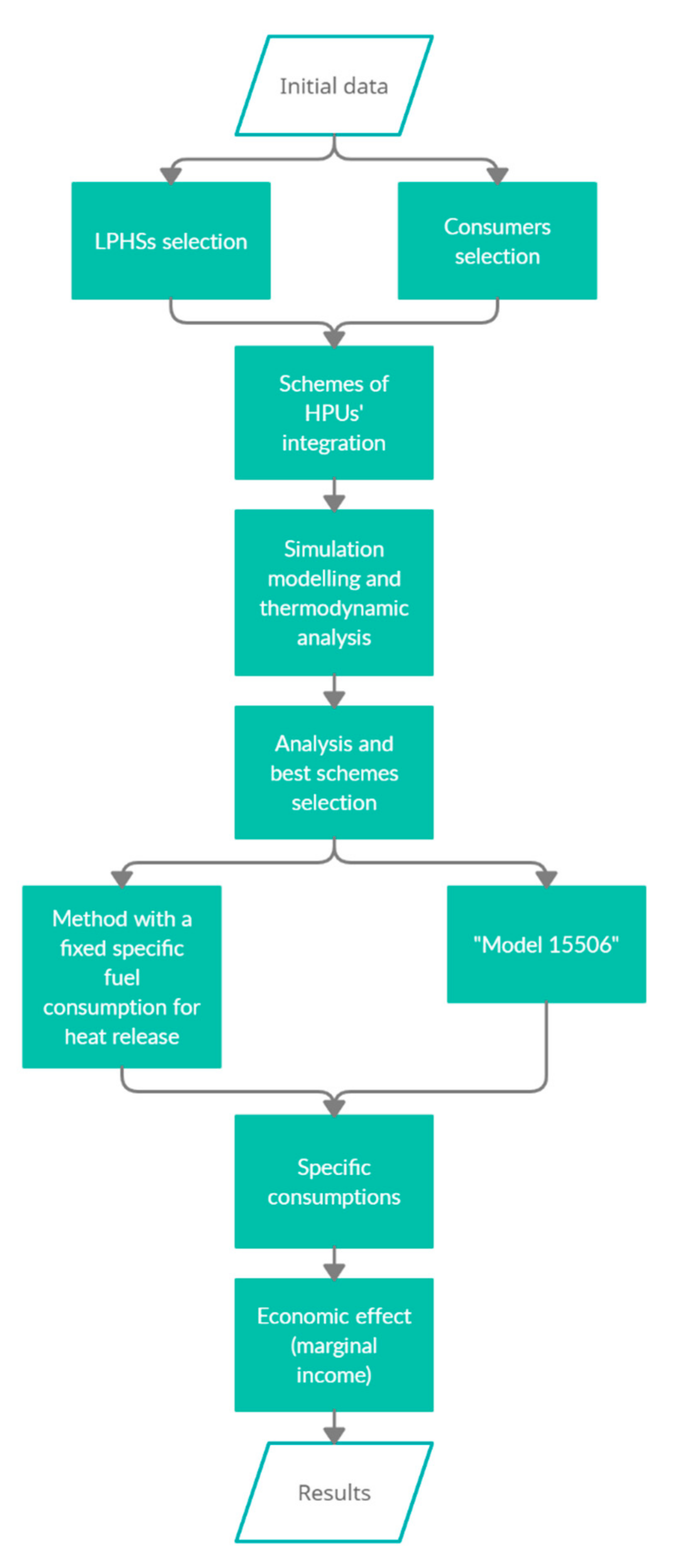
The algorithm according to which the study was carried out is shown in Figure 1.
To analyze the possibility of including heat pumps in a thermal circuit of a CCGT-CHPP unit, it is necessary to have initial data, which can consist of:
- thermal and technological schemes of systems and subsystems of CCGT-CHPP;
- normative and technical characteristics of the main and auxiliary facilities;
- operating modes maps for turbines and boilers;
- assessment of equipment;
- calculated and reference data for a steam turbine (heat balances);
- facilities operation manuals;
- daily lists and statistical information on the operating modes of a plant (duration and parameters);
- theoretical and practical methods for calculating the specific consumption of equivalent fuel, suitable for use at a CCGT-CHPP;
- aspects of the sale of heat and electricity: tariffs, expected growth rates of prices for heat energy, electricity, etc.;
- tariffs for the purchase of electricity for own needs.
The development of a technical solution to improve the cogeneration process at a CHPP using heat pumps includes: selection of a low-potential heat source; selection of heat consumer from a HPU; selection of a location for a heat pump; determination of HPU’s power limitations; selection of a HPU scheme; selection of a HPU working fluid.
The first stage in the analysis of the feasibility of integrating HPUs into CCGT-CHPPs is the assessment of possible low-potential heat sources. The assessment should be carried out taking into account the aspects of plants’ operation modes. The analysis of the potential possibilities of such heat sources at CHPPs includes the following stages:
- search for possible sources of low-grade heat based on the analysis of a technological scheme and statistical data on operating modes of a plant;
- analysis of a potential and a temperature level of these sources according to statistical data and nominal characteristics of facilities;
- identification of advantages and disadvantages of each source for their use in a HPU evaporator;
- selection of optimal LPHSs.
The choice of a low-potential heat source for heat recovery in a HPU determines the power range of a HPU.
When choosing a consumer of heat from a HPU, the primary task is to analyze modes and determine places at a CHPP with the need for additional heat supply, as well as places where it is possible to reduce the extraction of heat of high potential suitable for supply to the consumer.
To select the optimal consumer of heat from HPU, we need to take into account a number of factors: capacity of a HPU; scheme and working body of a HPU; distance from a HPU to a LPHS; place of integration to a CHPP; influence on operating modes of a CHPP equipment, etc.
As with the choice of a low-potential heat source, the choice of a heat consumer limits HPUs’ power range.
Obviously, a selection of a HPU’s location should take into account a distance from a selected LPHS and a selected heat consumer to the HPU, the availability of free space for the new equipment and its overall dimensions.
Determination of a HPU’s capacity limitations should be carried out by analyzing statistical information on a CHPP operation modes, information on prospective connections for gaining heat release from a CHPP, the economic life of facilities, and the probability of a planned output of heat sources at a plant (boilers, raw water heaters, etc.).
To determine the effectiveness of the integration of heat pumps at a CCGT-CHPP, it is proposed to apply the methods of mathematical modeling, thermodynamic analysis of heat pump cycles and technical and economic calculations. To assess the impact of heat pumps’ integration on operating modes of a CCGT, the key technical and economic indicators of operating modes without heat pump installations and with heat pumps should be compared. Also changes in marginal income are assessed.
The choice of the method of element-by-element modeling for calculating key technical and economic indicators allows us to create models of CHPPs with any thermal schemes, with a different composition of equipment, and various switchings between equipment. All these make it possible to determine the nominal operating modes of equipment and modes with partial heat and electricity capacities, shutdown of individual elements, or entire groups of equipment, i.e., the created models make it possible to calculate any stationary operating mode of a CHPP unit.
The following are considered key technical and economic indicators: specific consumption of the reference fuel for power generation; specific consumption of the reference fuel for heat release; coefficient of fuel heat utilization (CFHU).
Specific consumption of the reference fuel for electricity release with a HPU, t r.f./(MW∙h):
where: BfuelN—the reference fuel consumption for power generation, t r.f./h; N—power generation, MW; Neown—the electricity consumption for own needs, MW; NeHPU—electricity costs for a heat pump, determined primarily by costs of a compressor drive (for modes with a vapor-compression heat pump (VCHP)), MW.
Specific consumption of the reference fuel for heat release with a HPU, t r.f./(MW∙h):
where: Bfuelheat—the reference fuel consumption for heat generation, t r.f./h; Qheat—the total heat release, MW; QHPU—heat release from a HPU, MW; QstAHP—heat consumption from the steam extraction to an AHP generator, MW.
The coefficient of fuel heat utilization is equal to the sum of the supplied energy (electrical and thermal), divided by the consumed heat of the fuel (Equation (3)):
where: Ne—the electricity release from ST and GTs generators, MW; Qfuel—the heat from gas burned in combustion chambers of GTs, MW; Bfuel—the reference fuel consumption, t r.f./h; 7 Gcal/t r.f.—the reference fuel combustion value; 1.163—the coefficient for converting Gcal/h to MW: 1.163 MW = 1 Gcal/h.
The CFHU during operation of various types of HPUs as part of the first stage is determined by the Equation (4):
where: NeST—steam turbine power generation, MW; NeGT—gas turbine power generation, MW; Qbbcond—heat release in make-up water from the built-in tube bundle of the steam turbine, MW; QNH1 and QNH2—heat release from network heaters, MW; QWWHE1 and QWWHE2—heat release from water-to-water heat exchangers, MW; QBCC—heat release from boiler condensate cooler, MW.
Nowadays in the Russian Federation there is no officially approved methodology for calculating the technical and economic indicators of power gas turbine plants (CCGTs, GTs).
This subsection presents the methods for calculating the specific fuel consumption for the of heat and electricity release. They were calculated using two methods.
The first method is with a fixed specific fuel consumption for the heat release. This method of calculating specific fuel consumption is used by Territorial Generating Company No. 1 (TGC-1) in its sales activities. TGC-1 is the leading producer of electricity and heat in the North-West region of Russia. It operates 52 electric generating stations in four regions of Russia: St. Petersburg, Republic of Karelia, Leningrad Oblast, and Murmansk Oblast. The data of the specific fuel consumption for a heat release, as well as the tariff cost of heat, own needs and the supplied electric power were obtained from the sales department of TGC-1 and are relevant for the first quarter of 2020.
In this method, the specific fuel consumption for the heat release is set: 132.42 kg/MW.
Then the specific fuel consumption for the electricity release is calculated:
where: K = 1.154—coefficient for converting the natural gas mass flow rate to the reference fuel consumption [18]; Ggas—gas mass flow rate into the combustion chamber of one gas turbine, t/h; ρgas—gas density, kg/nm3.
The second method—“model 15506”—is presented in the methodology for making reports on power plants [19]. The emphasis in this algorithm is on the simplification of the calculations and the reduction of the algorithm to specific schemes of CCGTs of the utilization type.
The split ratio of fuel costs for the electricity release:
where: QNCV = 35.88 MJ/m3—net calorific value of the gas; ηCCGT—efficiency of CCGT, —.
Specific fuel consumption for the electricity release:
Then the specific fuel consumption for the heat release:
The economic effect as a simplified margin income for modes aimed at increasing the release of heat (with a constant level of electricity at the terminals of generators) is presented in Equation (9). It is calculated as a difference between the profit received from the operation of the HPU (heat release) and the corresponding increase of electricity costs for the HPU compressor drive (an increase of own needs and an increase in the cost of electricity production lead to an increase in specific fuel consumption for electricity). Calculations were made according to tariffs for energy carriers (heat and electricity) for TGC-1 in the first quarter 2020.
where: ΔQH—increment of heat as a result of the introduction of HPU, MW; CT = 8.21 $/(MW·h)—tariff cost of thermal energy for vacation; ΔEON—increase in electricity costs for own needs as a result of the introduction of HPU, MW; CON = 14.78 $/(MW·h)—tariff value of electric energy for own needs.
Economic effect for modes aimed at increasing the release of electrical energy (with a constant level of the heat release):
where: ΔNe—increment in the electricity release, MW; Ce = 14.41 $/(MW·h)—tariff cost of electricity for the electricity release.
2.2. Heat Pump Units (HPUs)
A heat pump unit is a technical device designed to transfer heat from a low-potential heat source to a heat carrier with a high temperature (a consumer) by means of work costs or by supplying external energy. In this paper, two types of heat pump are considered: vapor-compression heat pump (VCHP) and AHP.
The operation of a VCHP is characterized by the energy conversion coefficient. This coefficient depends on the temperature difference between a low-potential heat source and a consumer [20,21]. In this paper, sources are considered, the temperature level of which is quite variable throughout the year. For example, the temperature of the make-up water before heating in the vacuum deaeration system of a CCGT-450 may have a temperature of (+1…+20) °C, depending on the season.
Therefore, we can say that the efficiency of a vapor-compression heat pump’s operation strongly depends on operating modes of a CCGT unit. For this reason, there is a need for a complete calculation of the thermal cycle of work and indicators of a VCHP when using thermodynamic properties of it working fluid.
It is sensible to compare the efficiency of VCHPs of different layouts and with different working refrigerants by means of comparing their coefficients. In this research R134a, which has become widespread and is ozone-safe, was chosen as the refrigerant of vapor-compression heat pump [22].
Three types of layout of VCHPs are examined:
- The simple VCHP;
- The VCHP with a regenerative heat exchanger (RHE);
- The VCHP with a RHE and a supercooler (Sc).
The built-in RHE makes it possible to achieve subcooling of the refrigerant at the intake to the throttle in the heat pump cycle. This increases the efficiency of throttle operation, as well as superheats the refrigerant vapor after the evaporator. Thus, the efficiency of the compressor increases. HPUs of medium power usually are supplemented with a RHE, which allows to reduce the cost of the compressor drive, i.e., for the power unit’s own needs. HPUs of high power are modified by RHE and supercooler for deeper cooling of low-potential heat agents and increasing the efficiency of the heat transfer [22].
To assess the characteristics of VCHPs and their thermal cycles, the program “CoolPack” (Denmark) is used [23].
The energy efficiency of an AHP is characterized by the ratio of the heat released by an AHP to the heat spent in its generator. This ratio is called the transformation ratio. The coefficient is mainly determined by the type of an AHP (single-stage or two-stage) and does not depend on the temperature difference between the LPHS and the heat consumer.
Technical characteristics are presented in Table 1.
3. Modeling Heat Pumps as Part of a Combined-Cycle Gas Turbine (CCGT)
3.1. Modelling of CCGT-450
The analysis of the impact of integrate HPUs on the operation of CCGT-CHPPs was carried out based on simulations developed by the CAD system “United Cycle” (Russia). “United Cycle” uses an algorithm that allows to use the parameters of one basic option to determine the characteristics of power plants with technological schemes of any complexity for various stationary operating modes of the main and auxiliary equipment [25,26,27].
Modeling is a multi-step process. Determination of the structure of the mathematical model’s equations occurs at the stage of creating a thermal diagram in a CAD designer, the calculated thermal diagram of CCGT-450T is shown in Figure 2. Furthermore, at the stage of parametrization, coefficients of equations of heat, material and hydraulic balances, characteristics of changes in various parameters (efficiency, enthalpies, etc.), and limitations of the mathematical model are determined. For the first stage of mathematical modeling all data used for parametrization were obtained from the manufacturer’s catalog. In the second stage, the parametrization was carried out in the presence of data from a real station, which has a CCGT-450 unit.
The verification of a model’s adequacy is carried out by comparing results of a calculation of a mathematical model with control indicators of facilities. As benchmarks, we used the data obtained on the technical conditions for the manufacture and supply of steam and gas turbines, waste heat boilers and the calculated and reference data on the steam turbine, as well as the actual performance of the power unit (data of the automated process control system). The comparison is made for several typical operating modes of the CCGT unit, which are determined by different temperatures of an ambient air and relative electrical loads of the gas turbine unit.
An example of comparing such indicators for a typical mode with an outside air temperature of +15 °C and a relative load of one of the gas turbines equal to 100% is presented in Table 2. The average relative deviation is 1.17%.
In a similar way, 2 more typical operating modes were analyzed: winter mode with an outside air temperature of −26 °C with two gas turbine units operating at 100% load; summer condensation mode with an outside air temperature of +15 °C with the operation of two gas turbines at 100% load. The analysis of the model verification showed deviations from the control parameters of no more than 2.5%, the average value of the deviations was 0.9%. The difference between the control and calculated parameters of the unit operation mode is explained by the fact that design calculations were used as control characteristics for separately operating equipment—a gas turbine, a waste-heat boiler, a steam turbine, and not the entire system as a whole.
Correctly constructed and parameterized models of power plants make it possible to simulate as many operating modes as exists in real facilities. In simulation modeling there is an assumption that calculations are made only for stationary operating conditions.
The CCGT-450 unit is a binary CCGT unit with a double-block scheme. This block is focused on the generation of heat and electricity.
The CCGT main facilities are:
- Two gas turbines with a nominal capacity of 160 MW, manufactured under license from Siemens (analogue of GT type V94.2);
- Two waste heat boilers with steam performance of 230 t/h (63.34 kg/s), having two steam circuits of high pressure and low pressure;
- One steam turbine with a nominal capacity of 125 MW.
The CCGT-450 thermal scheme created in “United Cycle” to perform the simulations is shown in Figure 2.
Table 2 compares the data of the summer operation of the unit from the regulatory documentation (the regime card for the summer mode)—control data—and the data obtained using UC.
3.2. Selection of Sources and Consumers of Low-Potential Heat
The list of low-potential heat sources, that can be found at a power plant, includes the environment of cooling systems as well as waste systems. LPHSs are presented in Table 3.
These LPHSs have the following advantages:
- Reduced aggressiveness of agents used;
- High temperature level;
- Stability of parameters of environments throughout the whole year;
- Uniformity of possible circuit solutions.
The disadvantage of some sources is the dependence of their parameters on the operating modes of the station equipment. In this regard, it is worth considering the requirements of the reliability of the main and auxiliary equipment of a CHPP when developing HPUs’ integration schemes.
In addition to the aforementioned sources of heat, it is worth mentioning one potential source—air at the intake of the gas turbine compressor during operation with high outdoor temperatures. Because of the heating of the air in the summer period, there is a noticeable decrease in the generated power of the gas turbine unit (Figure 3). Figure 3 shows the effects of the ambient air temperature on a GT power generation. The relative power of the GT is the power referred to the gas turbine nominal value of power.
During the summer period of the station operation, cooling the air supplied to the gas turbine compressor can increase the generation of electricity at the terminals of the gas turbine generator and thereby increase the station’s marginal income from the sale of additional electricity generation in the electricity and capacity market.
Of all the above options, in this work, the cooling water of the circulating cooling system of the steam turbine condenser, as well as the air at the intake of the gas turbine compressor, are considered as sources of the low-potential heat.
Below in Table 4 and Table 5 the advantages and disadvantages of the selected low-potential heat sources are shown.
During the development of circuit solutions for the integration of HPUs into the CCGT-CHPP, when choosing a consumer of heat produced by a heat pump one should be guided by the influence of such integration on the operation of the station, as well as the location of the consumer.
The following are considered as heat consumers:
- Make-up water of the heating system;
- Return network water (RNW) of the heating system;
- Air at the gas turbine compressor intake.
The options of RNW and make-up water heating are equivalent for the total heat balance of a power plant. But the efficiency of the heat pump depends on the magnitude of the temperature difference between the low-potential and high-potential heat carriers: the smaller the difference, the more efficiently a HPU works.
The advantages of heating RNW:
- Decrease in the load of the heating extraction of the turbine with a subsequent increase in power generation;
- Stability of temperature level and flow rate during the heating period.
Disadvantages:
- High temperature difference between a LPHS and a consumer;
- Influence on the operating modes of the vacuum deaerator (its mode depends on a temperature of the heating agent—RNW after network heaters);
- Influence on the operating modes of the ST and consequently the CCGT plant [29].
Benefits of heating make-up water:
- Efficient operation of HPU due to low temperature difference between a LPHS and a consumer;
- Possible decrease in the load of the heating extraction of the turbine with a subsequent increase in power generation;
- Reducing the selection of heating water to the vacuum deaerator of the make-up water of the heating system.
Disadvantages:
- Limiting the maximum temperature before the vacuum deaerator [29];
- Influence on the operating modes of the vacuum deaerator;
- Low water mass flow rate for a closed heating system;
- Influence on the operating modes of the ST and consequently the CCGT plant [29];
- Dependence on the operating mode of the built-in condenser bundle and the boiler condensate cooler (BCC).
Because of the aforementioned, the option of using the released heat for heating the make-up of the heating system before the vacuum deaerator is preferable. Since the heat supply system of St. Petersburg at the moment is gradually transitioning from an open type to a closed one, heating make-up water is considered with a flow rate of 800 t/h (the same amount of water is used in the CCGT-450 operating at Yuzhnaya CHPP-22 in St. Petersburg, Russia), as well as heating make-up water with a flow rate of 1500 t/h (as in the CCGT-450 operating at Pravoberezhnaya TPP-5 in St. Petersburg, Russia). Modes with a make-up water flow rate of 1500 t/h are considered as transient modes with a gradual transition from an open heat supply system to a closed one. The heating unit (HU) in which the HPU is integrated is described in Section 3.2.1.
In winter, high air humidity can lead to icing of the filters of the integrated air intake filter. To combat this, the anti-icing system of the gas turbine compressor air intake filter (AIF) is activated, which leads to a decrease in electricity generation at the terminals of the GT generator (Figure 4a). Therefore, in order to increase the generation of electricity, it makes sense to heat the air before the AIF without using the AIS. The air intake filter and its anti-icing system are briefly described in Section 3.2.2.
The advantages of using this consumer are:
- Increase in electricity generation by reducing the air intake after the compressor for the anti-icing system [28].
Disadvantages:
- Influence on the operating modes of the GT and consequently the CCGT plant [29].
3.2.1. The Heating Unit
The heating unit of the CCGT-450, which serves for the preparation and heating of the network water, consists of two network heaters (NH), each of which receives extracted steam from low- and high-pressure steam turbine cylinders (LPC ST and HPC ST). For the purpose of heating, the make-up water first passes the built-in bundle of the condenser, and then goes through the boiler condenser cooler (BCC), which serves to cool the condensate of network heaters and the steam separator between the HPC ST and the LPC ST. Furthermore, after passing through the water-to-water heat exchangers (WWHE), where the make-up water is heated by the extraction of from the condensate gas heater, which is essentially an economizer of the low-pressure circuit of the WHB. As a result, before mixing into the network water circuit before NHs, make-up water is deaerated in a vacuum deaerator (VD), the heating agent of which is the selection of network water after network heaters.
3.2.2. The Air Intake Filter
The gas turbine has an air intake filter to clean the air before entering the compressor. The AIF includes sets of coarse and fine filters, which are installed in a multi-store box. Thanks to them, the permissible concentration of dust in the air path is ensured.
Due to the cold climate in Russia, there is a danger of icing for the filters of the air intake filter. This problem is particularly relevant in regions with a high air humidity as is the case of St. Petersburg. Therefore, the air intake of the AIF includes the anti-icing system, which provides air heating. For this, hot air with a temperature of 310 °C and a pressure of 1.2 MPa is taken directly from the sixteenth compressor stage and mixed into the main air stream through pipes with special perforations to obtain a mixture of the required temperature. AIS is switched on in the range of ambient air temperatures at the compressor intake (−5 … +5) °C and relative humidity of 80% or more. The AIS should ensure a decrease in the relative air humidity to 60–70%. After passing through the filter box, the purified air is supplied through the air duct to the gas turbine compressor.
As can be seen from the correction graphs presented below (Figure 4a,b), the switch on of the AIS in the winter period has the following impact on the CCGT-450 performance:
- The maximum power reduction at the generator terminals of each of the two gas turbines is 24 MW;
- The maximum reduction in the gross efficiency of the unit is 4.5%.
- The maximum reduction in flue gas at the outlet of each of the two gas turbines is 13.9 kg/s [30];
- The maximum reduction in power at the terminals of the ST generator (when two GTs operate) is 4 MW [30].
It follows from the above that the air at the intake of the gas turbine in winter is a good consumer of heat from a HPU. The use of HPUs to replace the AIS can enhance the electricity production by the CCGT-450 and its efficiency in general.
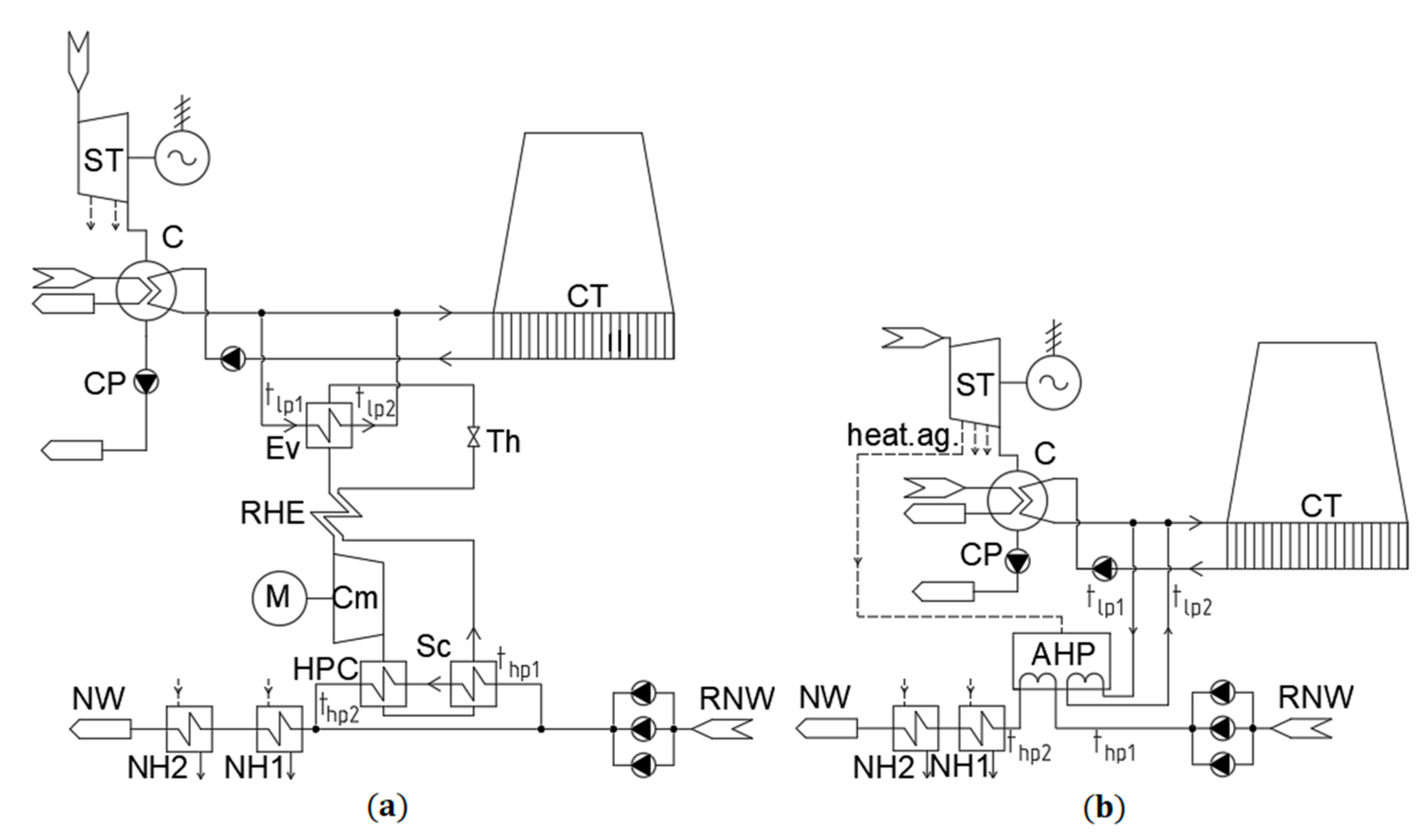
3.3. Schemes of HPUs Integration into a Combined-Cycle Gas Turbine Combined Heat and Power Plant (CCGT-CHPP)
For heating the return network water and make-up water, the following solutions for the integration of HPU with heat release in the range of 12.26 to 40.00 MW are proposed:
- For heating return network water—a HPU installed before the unit mixing RNW with make-up water after the vacuum deaerator. The cooling water of the condenser acts as a LPHS (Figure 5);
For heating the air in winter, it is proposed to integrate a heat pump before the intake of AIF. The cooling water of the condenser acts as a LPHS (Figure 8).
4. Results and Discussion
4.1. Simulation Results
4.1.1. Use of HPUs for Heating Return Network Water
First, the feasibility of using a HPU for heating RNW is considered. The average winter modes with low heating loads were modeled with and without the HPUs integration. The simulations were developed keeping constant the amount of heat release. RNW mass flow rate amounted to 5827 t/h. Circulating water mass flow rate is 10,300 t/h. The results for these modes are presented in Table 6 and in Figure 9.
It is impractical to heat the return network water when integrating a HPU into the CCGT-450 unlike in [16,17]. An increase in the capacity of the HPU leads to a proportional increase in the “additional” own needs in the case of using the VCHP, as well as to a decrease of the energy conversion coefficient. This is due to the dependence of the HPU operation efficiency on the level of the temperature difference between a heat source and a consumer.
In this mode, the constant heat release is maintained to study the effect of steam extraction for the AHP generator on the electricity underproduction level. With an increase in the power of the heat pump unit, the release of electricity significantly decreased when using AHP based on AHP2-P. This is due to the high level of power underproduction factor of the extracted steam. Obviously, steam extraction (followed by throttling, which means—with energy losses) after the high-pressure control valve is a rather bad solution. The heat pump based on AHP-P in this regard showed itself much better due to the decrease in the pressure of the selected steam on the AHP generator and, consequently, losses.
4.1.2. Use of HPUs for Heating Make-Up Water with a Flow Rate of 800 t/h
The next modeled and calculated modes are winter modes with low heating loads without and with HPU for heating the make-up water. The power of the HPU is chosen so as not to exceed the 45 °C limitation of make-up water temperature before the vacuum deaerator [29].
The simulations were developed keeping constant the amount of heat release. The make-up flow rate is 800 t/h. Circulating water mass flow rate—10,300 t/h. The results for these modes are presented in Table 7 and Figure 10.
According to the results—the energy conversion coefficient increased and the energy consumption of the VCHP compressor decreased—it can be concluded that the thesis that the higher the efficiency of the HPU the lower the temperature difference between a LPHS and a consumer, is certainly applicable to the VCHP.
Based on the results of modeling and calculation of this mode, it was decided not to use further AHPs based on AHP2-P due to its lower efficiency in comparison with VCHP and a strong influence on the ST operation mode due to poor choice of the place of steam extraction of the AHP2-P generator and, as a consequence, extremely high level of underproduction of electricity.
4.1.3. Use of HPUs for Heating Make-Up Water with a Flow Rate of 1500 t/h
During simulating the winter modes with low heating loads, a constant level of electric power is maintained at the terminals of the ST and GT generators. The make-up flow rate is 1500 t/h. Circulating water mass flow rate—6400 t/h.
A significant decrease in the heat release due to the use of AHP explains why previously only modes maintaining the constant release of heat (not electricity) were considered. Therefore, in the future, the use of AHP is not considered.
Based on the results of considering the influence of the integration of the VCHP with a RHE and a supercooler into the CCGT-450 scheme for heating the make-up with a flow rate of 1500 t/h, it can be seen that an increase in the capacity of the VCHP leads to a significant increase in the undersupply of electricity. Probably, with more powerful VCHP, this mode can be low-cost or even unprofitable.
Also, starting with a capacity of 30 MW in this type of mode (winter with low loads), there is a lack of low-potential coolant. Consequently, the use of VCHPs with a capacity of 30 MW and above is not feasible specifically for these considered modes (modes 5, 6 and 7 in Table 8).
4.1.4. Use of HPUs for Heating the Intake Air
Winter modes with low heat loads are examined. The simulation maintains the constant release of heat. This is due to the fact that the use of AIS leads to a decrease in the release of electricity, and it is precisely such an aspect as electricity generation that is most indicative for this mode for assessing the impact of HPU integration for heating the intake air.
Due to the low level of required heat release from a VCHP, the VCHPs of a simple scheme are considered.
Circulating water mass flow rate—10,300 t/h.
The simulation and calculation results are presented in Table 9.
The circuit design considered, as well as in work [8], gave a significant increase in the supply of electricity (20%). Table 9 shows that the use of a VCHP as a replacement for an AIS leads to a noticeable increase not only in the release of electricity from the unit, but in all output characteristics of a CCGT.
The increase in the efficiency of the gas turbine as part of the CCGT-450 was in a range of 2.93% to 4.89% depending on a mode. The result obtained is similar to the result in [6].
4.1.5. Use of HPUs for Cooling the Intake Air
Summer modes are considered. During the simulation, a constant release of heat is maintained, since the feasibility of using HPU for air cooling is studied in order to increase the release of electricity. For this, all three variants of the VCHP layout are considered: the simplest scheme, a scheme with a regenerative heat exchanger, a scheme with a RHE and a supercooler.
The simulation and calculation results are presented in Table 10.
The VCHP with a RHE and a supercooler showed itself in the best way—for this option, the highest values of the energy conversion coefficient and, as a consequence, an increase in the release of electricity from the unit were obtained. The RHE option showed itself slightly better than the simplest VCHP scheme, if we look at the energy conversation coefficients. However, this “gain” is obviously small. Therefore, due to the fact that the VCHP scheme with a RHE is technically more difficult to maintain, and also more expensive due to the presence of such a technical component as a RHE, of the two options (modes 2 and 3 in Table 10), it makes sense to give preference to the VCHP of a simple scheme (mode 2).
4.2. Technical and Economic Indicators
This subsection discusses the modes that showed positive results during the previous section are considered, namely:
4.2.1. Use of HPUs for Heating Make-Up Water with a Flow Rate of 1500 t/h
The results of calculating the technical and economic indicators are shown in Figure 12 and Table 11.
Starting from a capacity of 22.5 MW, an increase in the power level of the VCHP, that is, the heat given off by the VCHP condenser, leads to a negative economic effect. Also, due to a decrease in the electricity release in connection with a significant increase in own needs (Table 8), the specific fuel consumption for the electricity release also increases.
The modeling of HPUs integration for heating the make-up at its mass flow rate of 1500 t/h shows the expediency of using the vapor-compression heat pump with a RHE and a supercooler with a capacity of 20 MW. This decision leads to an increase in the heat release by 8.1 MW (Table 8, Figure 11), as well as a decrease in specific fuel consumption for the electricity release, if we consider it using the method with a fixed specific fuel consumption for heat release currently used by TGC-1. With the integration of this capacity into the CCGT-CHPP scheme, the VCHP power supply decreases by almost 4 MW (Table 8, Figure 11). However, the mode considered was aimed at increasing the release of heat, so that such a result can be considered satisfactory.
4.2.2. Use of HPUs for Heating the Intake Air
The results of calculating the technical and economic indicators are shown in Table 12.
The use of VCHPs for heating air in order to prevent icing of the air intake filter at high air humidity in winter is definitely more advantageous than using the anti-icing system as part of a gas turbine unit.
This circuit design is characterized by a significant increase in the release of electrical energy (up to 14.87% relative to the initial mode).
Despite the increase in gas mass flow rate into the combustion chambers of the gas turbine units, which is associated with maintaining a constant relative power of the gas turbine unit during modeling in UC, the specific reference fuel consumption for the electricity release is noticeably reduced (up to 10.76% in the case of heating air to a temperature of 8 °C), regardless of the method for calculation of specific fuel consumption. However, when using the method of calculating the specific fuel for the “model 15506”, there is a slight increase in the specific reference fuel consumption for heat release.
The simulation of HPUs integration for heating air at the gas turbine intake at the winter operating mode with low heat loads shows the unambiguous expediency of replacing the anti-icing system of the gas turbine with a vapor compression heat pump. This solution is relevant for CCGT-CHP plants built in an area with an average air temperature in winter in the range (−5 …+5) °C with a relative humidity of 80% or more.
4.2.3. Use of HPUs for Cooling the Intake Air
The results of calculating technical and economic indicators are shown in Table 13.
Similar to the previous case, the increase in fuel consumption is associated with maintaining a constant relative power of the gas turbine unit during the simulation in UC.
According to the results of modeling the introduction of a VCHP in order to cool the air to increase the power generated by a gas turbine, the most advantageous is the use of the VCHP with a RHE and supercooler.
The advantage of the VCHP scheme, which has a RHE, over the simple-scheme VCHP is insignificant. Therefore, of these two options, preference should be given to the simple-scheme VCHP.
5. Conclusions
The presented research work can be summarized in the following points:
- Different solutions for integrating the HPUs in a combined-cycle gas turbine (CCGT) plant, the CCGT-450, are analyzed based on simulations developed on “United Cycle” computer-aided design (CAD) system.
- Based on the results of the selection of low-potential heat sources and consumers, circuit solutions for the integration of HPUs were proposed:
- -
- the use a HPU to heat the GT intake air and replace anti-icing system, over the winter at high humidity conditions;
- -
- the use of heat pumps for air cooling at the intake of a gas turbine unit in the summer period of operation;
- -
- the use of heat pumps for heating water of a heating unit (return network or make-up water).
- The best solution was obtained for the winter operation mode replacing the ant-icing system by a HPU. This allows us to reduce the underproduction of electricity, associated with the losses because of the anti-icing system, up to 14.87%, when heating the inlet air from −2 °C to 8 °C. The overall efficiency of the CCGT unit increases from 40.00% to 44.82%. Using a HPU with a 5.04 MW capacity can save $309,640 per each MW per quarter.
Author Contributions
Conceptualization, I.A. and K.K.; methodology, I.A.; software, I.A.; validation, V.S., I.A. and K.K.; formal analysis, I.A.; investigation, K.K.; resources, I.A.; data curation, V.S.; writing—original draft preparation, K.K.; writing—review and editing, I.A. and K.K.; visualization, I.A. and K.K.; supervision, I.A.; project administration, V.S.; funding acquisition, V.S. All authors have read and agreed to the published version of the manuscript.
Funding
The paper was prepared at Higher School of Nuclear and Heat Power Engineering at Peter the Great St. Petersburg Polytechnic University. The APC was funded by this university.
Institutional Review Board Statement
Not applicable.
Informed Consent Statement
Not applicable.
Data Availability Statement
Data sharing not applicable.
Conflicts of Interest
The authors declare no conflict of interest.
Nomenclature
| Abbreviation | |
| AHP | absorption heat pump |
| AIF | air intake filter |
| AIS | anti-icing system |
| BCC | boiler condensate cooler |
| C | steam turbine condenser |
| CC | combustion chamber |
| CCGT | combined cycle gas turbine |
| CFHU | coefficient of fuel heat utilization |
| CHPP | combined heat and power plant |
| Cm | compressor |
| CP | condensate pump CAD; |
| CT | cooling tower of the circulating water supply system |
| heat.ag. | the heating agent of a AHP generator (extracted steam from a ST) |
| CTW | chemically treated water |
| Ev | evaporator |
| GT | gas turbine |
| GT Cm | gas turbine compressor |
| HPC | vapor-compression heat pump condenser |
| HPC ST | high-pressure turbine cylinder |
| HPD | high pressure drum |
| HPU | heat pump unit |
| LPC ST | low-pressure turbine cylinder |
| LPD | low-pressure drum |
| LPHS | low-potential heat source |
| MW | make-up water NH |
| NH | network heater |
| NP | network pump |
| NW | network water |
| RHE | regenerative heat exchanger |
| RNW | return network water |
| Sc | supercooler |
| ST | steam turbine |
| Th | throttle |
| UC | “United Cycle” |
| VCHP | vapor-compression heat pump unit |
| VD | vacuum deaerator |
| WHB | waste heat boiler |
| WWHE | water-to-water heat exchanger |
| Variables and Coefficients | |
| be | specific consumption of the reference fuel for electricity release with a HPU, t r.f./(MW∙h) |
| BfuelN | the reference fuel consumption for power generation, t r.f./h |
| N | power generation, MW |
| Neown | the electricity consumption for own needs, MW |
| NeHPU | electricity costs for a heat pump, determined primarily by the costs of the compressor drive (for modes with VCHP), MW |
| bheat | specific consumption of the reference fuel for heat release with a HPU, t r.f./(MW∙h) |
| Bfuelheat | the reference fuel consumption for heat generation, t r.f./h |
| Qheat | the total heat release, MW |
| QHPU | heat release from a HPU, MW |
| QstAHP | heat consumption from the steam extraction to an AHP generator, MW |
| Ne | the electricity release from ST and GTs generators, MW |
| Qfuel | the heat from gas burned in combustion chambers of GTs, MW |
| Bfuel | the reference fuel consumption, t r.f./h |
| 7 Gcal/t r.f. | the reference fuel combustion value |
| 1.163 | the coefficient for converting Gcal/h to MW: 1.163 MW = 1 Gcal/h |
| NeST | steam turbine power generation, MW |
| NeGT | gas turbine power generation, MW |
| Qbbcond | heat release in make-up water from the built-in tube bundle of the steam turbine, MW |
| QNH1 and QNH2 | heat release from network heaters, MW |
| QWWHE1 and QWWHE2 | heat release from water-to-water heat exchangers, MW |
| QBCC | heat release from boiler condensate cooler, MW |
| K | coefficient for converting the natural gas mass flow rate to the reference fuel consumption, — |
| Ggas | gas mass flow rate into the combustion chamber of one gas turbine, t/h |
| ρgas | gas density, kg/nm3 |
| Ke.CCGT | the split ration of fuel costs for the electricity release, — |
| QNCV = 35.88 MJ/m3 | net calorific value of the gas, MJ/m3 |
| ηCCGT | efficiency of CCGT, - |
| EE | economic effect (simplified margin income), $ |
| ΔQH | increment of heat as a result of the introduction of HPU, MW |
| CT | tariff cost of thermal energy for vacation, $/MW |
| ΔEH | increase in electricity costs for own needs after the integration of HPUs, MW |
| CON | tariff value of electric energy for own needs, $/(MW·h) |
| ΔNe | increment in the electricity release, MW |
| Ce | tariff cost of electricity for the electricity release, $/(MW·h) |
| tlp1, tlp2 | temperature of LPHS before and after VCHP |
| thp1, thp2 | temperature of a consumer before and after VCHP |
References
- Aminov, Z.; Nakagoshi, N.; Xuan, T.D.; Higashi, O.; Alikulov, K. Evaluation of the energy efficiency of combined cycle gas turbine. Case study of Tashkent thermal power plant, Uzbekistan. Appl. Therm. Eng. 2016, 103, 501–509. [Google Scholar] [CrossRef]
- Treshcheva, M.; Anikina, I.; Sergeev, V.; Skulkin, S.; Treshchev, D. Selection of Heat Pump Capacity Used at Thermal Power Plants under Electricity Market Operating Conditions. Energies 2021, 14, 226. [Google Scholar] [CrossRef]
- Godoy, E.; Scenna, N.J.; Benz, S.J. Families of optimal thermodynamic solutions for combined cycle gas turbine (CCGT) power plants. Appl. Therm. Eng. 2010, 30, 569–576. [Google Scholar] [CrossRef]
- Pihl, E.; Heyne, S.; Thunman, H.; Johnsson, F. Highly efficient electricity generation from biomass by integration and hybridization with combined cycle gas turbine (CCGT) plants for natural gas. Energy 2010, 35, 4042–4052. [Google Scholar] [CrossRef]
- Leo, T.L.; Perez-Grande, I.; Perez-del-Notario, P. Gas turbine turbocharged by a steam turbine: A gas turbine solution increasing combined power plant efficiency and power. Appl. Therm. Eng. 2003, 23, 1913–1929. [Google Scholar] [CrossRef]
- Ponce Arrieta, F.R.; Silva Lora, E.E. Influence of ambient temperature on combined-cycle power-plant performance. Appl. Therm. Eng. 2005, 80, 261–272. [Google Scholar] [CrossRef]
- Colmenar-Santos, A.; Gomez-Camazon, D.; Rosales-Asensio, E.; Blanes-Peiro, J.-J. Technological improvements in energetic efficiency and sustainability in existing combined-cycle gas turbine (CCGT) power plants. Appl. Energy 2018, 223, 30–51. [Google Scholar] [CrossRef]
- Olivenza-Leon, D.; Medina, A.; Calvo Hernandez, A. Thermodynamic modeling of a hybrid solar gas-turbine power plant. Energy Convers. Manag. 2015, 93, 435–447. [Google Scholar] [CrossRef]
- Mendeleev, D.I.; Galitskii, Y.Y.; Marin, G.E.; Akhmetshin, A.R. Study of the work and efWficiency improvement of combined-cycle gas turbine plants. In Proceedings of the International Scientific and Technical Conference Smart Energy Systems 2019 (SES-2019), Kazan, Russia, 18–20 September 2019; Volume 124, p. 05061. [Google Scholar] [CrossRef] [Green Version]
- Mendeleev, D.I.; Maryin, G.E.; Akhmetshin, A.R. Improving the efficiency of combined-cycle plant by cooling incoming air using absorption refrigerating machine. In Proceeding of the International Scientific Electric Power Conference, Saint Petersburg, Russia, 23–24 May 2019; Volume 643, p. 012099. [Google Scholar] [CrossRef]
- Anikina, I.D.; Sergeyev, V.V.; Amosov, N.T.; Luchko, M.G. Heat pumps application in flow-sheet of heat generation at thermal power plants. Int. Sc. J. Altern. Energy Ecol. 2016, 3–4, 39–49. [Google Scholar] [CrossRef]
- Anikina, I.D.; Sergeyev, V.V. Heat pumps’ application for energy efficiency rising of steam-power HPP. St. Petersburg St. Polytec. Un. J. 2013, 3, 56–61. [Google Scholar]
- Alimgazin, A.S.; Alimgazina, S.G.; Zhumagulov, M.G. Heat pump in a new modular configuration to recover low-grade heat emissions at enterprises. In Proceedings of the High Speed Turbomachines and Electrical Drives Conference 2020 (HSTED-2020), Prague, Czech Republic, 14–15 May 2020; Volume 178, p. 01003. [Google Scholar] [CrossRef]
- Alimgazin, A.S.; Prishchepova, S.A.; Sultanguzin, I.A. The use of heat transformers for the low-temperature secondary energy resources recovery in non-ferrous metallurgy enterprises. In Proceedings of the High Speed Turbomachines and Electrical Drives Conference 2020 (HSTED-2020), Prague, Czech Republic, 14–15 May 2020; Volume 178, p. 01017. [Google Scholar] [CrossRef]
- Zhang, H.S.; Zhao, H.B.; Li, Z.L. Performance analysis of the coal-fired power plant with combined heat and power (CHP) based on absorption heat pumps. J. Energy Inst. 2016, 89, 70–80. [Google Scholar] [CrossRef]
- Zhang, H.S.; Zhao, H.B.; Li, Z.L.; Hu, E. Optimization Potentials for the Waste Heat Recovery of a Gas-steam Combined Cycle Power Plant Based on Absorption Heat Pump. J. Therm. Sci. 2019, 28, 283–293. [Google Scholar] [CrossRef]
- Vannoni, A.; Giugno, A.; Sorce, A. Integration of a flue gas condensing heat pump within a combined cycle: Thermodynamic, environmental and market assessment. Appl. Therm. Eng. 2021, 184, 116276. [Google Scholar] [CrossRef]
- Russian Agency of Statistics. Resolution of June 23, 1999 N 46. The Approval of “Methodological Provisions for Calculating the Fuel and Energy Balance of the Russian Federation in Accordance with International Practice”; Russian Agency of Statistics: Moscow, Russia, 1999. [Google Scholar]
- Methodology of Calculating the Actual Indicators of the CCGT Unit for Filling in the Model 15506 in Addition to RD 34.08.552-95. TGC-1. Saint Petersburg, Russia. 2012. Available online: https://files.stroyinf.ru/Data2/1/4294816/4294816548.pdf (accessed on 10 September 2020).
- Anikina, I.D. Heat pumps application for increasing the efficiency of the cogeneration at thermal power plants. In Proceedings of the Efficient Energetics—2015, St. Petersburg, Russia, 21–22 May 2015; pp. 7–13. [Google Scholar]
- Gorshkov, V.G. Teplovyye nasosy. Analiticheskiy obzor [Heat pumps. Analytical review]. Spravochnik Promyshlennogo Oborudovaniya 2004, 2, 47–80. Available online: http://allbeton.ru/upload/iblock/10e/teplovie-nasosi-analiticheskiy-obzor-qgorshkovt.pdf (accessed on 15 November 2020).
- Sergeyev, V.V.; Anikina, I.D.; Kalmykov, K.S.; Naletov, I.D. Efficiency of using heat pumps with various refrigerants in real steam turbine power units with PT-80 and T-250 turbines. In Proceedings of the International Scientific Conference on Energy, Environmental and Construction Engineering (EECE-2019), Saint-Petersburg, Russia, 19–20 November 2019; Volume 140, p. 10001. [Google Scholar] [CrossRef] [Green Version]
- Jakobsen, A.; Rasmussen, B.D.; Andersen, S.E. CoolPack—Simulation tools for refrigeration systems. Scan. Ref. 1999, 28, 7–10. [Google Scholar]
- Popov, A.V. Lithium bromide absorption machines for water cooling and heating. Energy Sav. 2007, 7, 52–55. [Google Scholar]
- Romanov, S.; Kutakhov, A.; Zhuk, N.; Demidov, O.; Romanov, K. “United Cycle” Software for Simulation of Flow Sheets of Power Plants. In Proceeding of the 16th International Conference on Efficiency, Cost, Optimization, Simulation, and Environmental Impact of Energy Systems (ECOS-2003), Copenhagen, Denmark, 30 June–2 July 2003; pp. 1691–1696. [Google Scholar]
- Demidov, O.; Kutakhov, A.; Romanov, S. Simulation of AVV1 St Power Plant with United Cycle Software. In Proceeding of the 16th International Conference on Efficiency, Cost, Optimization, Simulation, and Environmental Impact of Energy Systems (ECOS-2003), Copenhagen, Denmark, 30 June–2 July 2003; pp. 1697–1704. [Google Scholar]
- Demidov, O.I.; Zhuk, N.I.; Ivanov, V.A.; Koren, V.M.; Kutakhov, A.G.; Romanov, S.N. CAD “Teplovaya schema”: Complex automation of development, calculation and optimization of thermal schemes of power units on TPP and NPP. Proc. Power Mach. Plants 1999, 481, 115–123. [Google Scholar]
- Branch of “Power Machines—ZTL, LMZ, Elektrosila, Energomashexport” “Leningrad Metal Plant” in St. Petersburg, Operation Manual 3170107. “Leningrad Metal Plant”; TGC-1: Saint Petersburg, Russia, 2008.
- Anikina, I.D. Influence of heat pumps inclusion in deaeration scheme of heating network make-up water on the operating modes of the TPP. In Proceedings of the International Scientific Conference on Energy, Environmental and Construction Engineering EECE-2018, Saint-Petersburg, Russia, 19–20 November 2018; Volume 245, p. 15004. [Google Scholar] [CrossRef]
- Operating Instructions for the Integrated Air Intake Filter (AIF) for the Gas Turbine GTU-160 of the POWER Unit 4; TGC-1: Saint Petersburg, Russia, 2016.
- Treshcheva, M.; Treshchev, D.; Anikina, I.; Skulkin, S. The potential for reducing TPP water consumption through the use of heat pumps. In Proceedings of the International Scientific Conference on Energy, Environmental and Construction Engineering (EECE-2019), Saint-Petersburg, Russia, 19–20 November 2019; Volume 140, p. 11001. [Google Scholar] [CrossRef] [Green Version]
Figure 1.
Flowchart of the methodology for analyzing the possibility of using heat pump units (HPUs) in the technological scheme of combined-cycle gas turbines (CCGTs).
Figure 1.
Flowchart of the methodology for analyzing the possibility of using heat pump units (HPUs) in the technological scheme of combined-cycle gas turbines (CCGTs).

Figure 2.
CCGT-450 thermal scheme model. ST—steam turbine; GT—gas turbine; HPD—high pressure drum; LPD—low-pressure drum; WWHE—water-to-water heat exchanger; HPC ST—high-pressure turbine cylinder; LPC ST—low-pressure turbine cylinder; WHB—waste heat boiler; C—steam turbine condenser; CP—condensate pump; HPU—heat pump unit; AHP—absorption heat pump; MW—make-up water; RNW—return network water; NW—network water; CTW—chemically treated water; BCC—boiler condensate cooler; NP—network pump; NH—network heater, VD—vacuum deaerator.

Figure 3.
Dependence of the relative power of the GT on the ambient air temperature [28].
Figure 3.
Dependence of the relative power of the GT on the ambient air temperature [28].

Figure 4.
Corrections graphs for the inclusion of the anti-icing system (AIS): (a) correction to GT power; (b) correction to gross efficiency of the CCGT-450 [30].
Figure 4.
Corrections graphs for the inclusion of the anti-icing system (AIS): (a) correction to GT power; (b) correction to gross efficiency of the CCGT-450 [30].

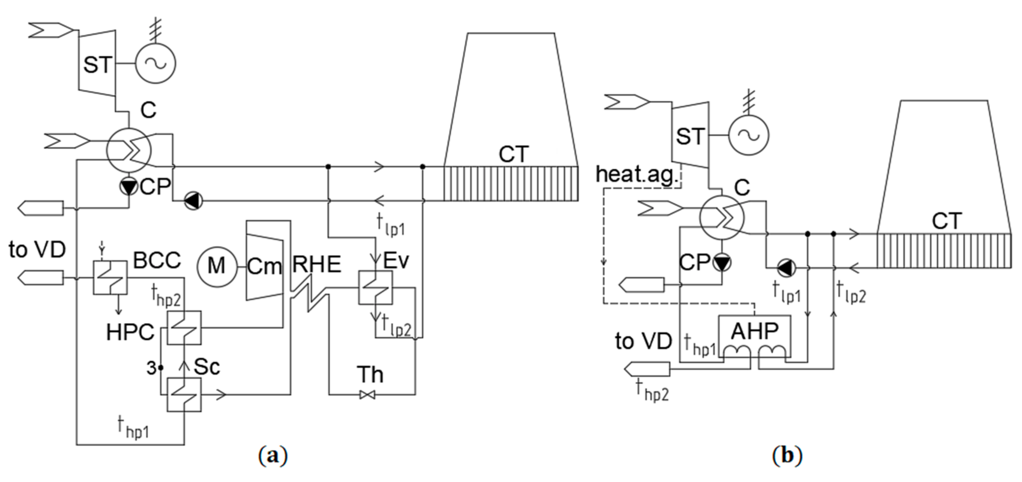
Figure 5.
Schemes of integrating vapor-compression heat pump (VCHP) with a regenerative heat exchanger (RHE) and a supercooler (Sc) (a), AHP (b) for heating RNW. Circulating water as a LPHS. ST—steam turbine; CT—cooling tower of the circulating water supply system, heat.ag.—the heating agent of an AHP generator (extracted steam from a ST); HPC—VCHP condenser, Th—throttle, Cm—compressor, Ev—evaporator; RHE—regenerative heat exchanger; Sc—supercooler. tlp1, tlp2—temperature of LPHS before and after VCHP; thp1, thp2—temperature of a consumer before and after VCHP.

Figure 6.
Shemes of integrating VCHP with a RHE and a Sc (a), AHP (b) for heating make-up water. Circulating water as a LPHS.
Figure 6.
Shemes of integrating VCHP with a RHE and a Sc (a), AHP (b) for heating make-up water. Circulating water as a LPHS.

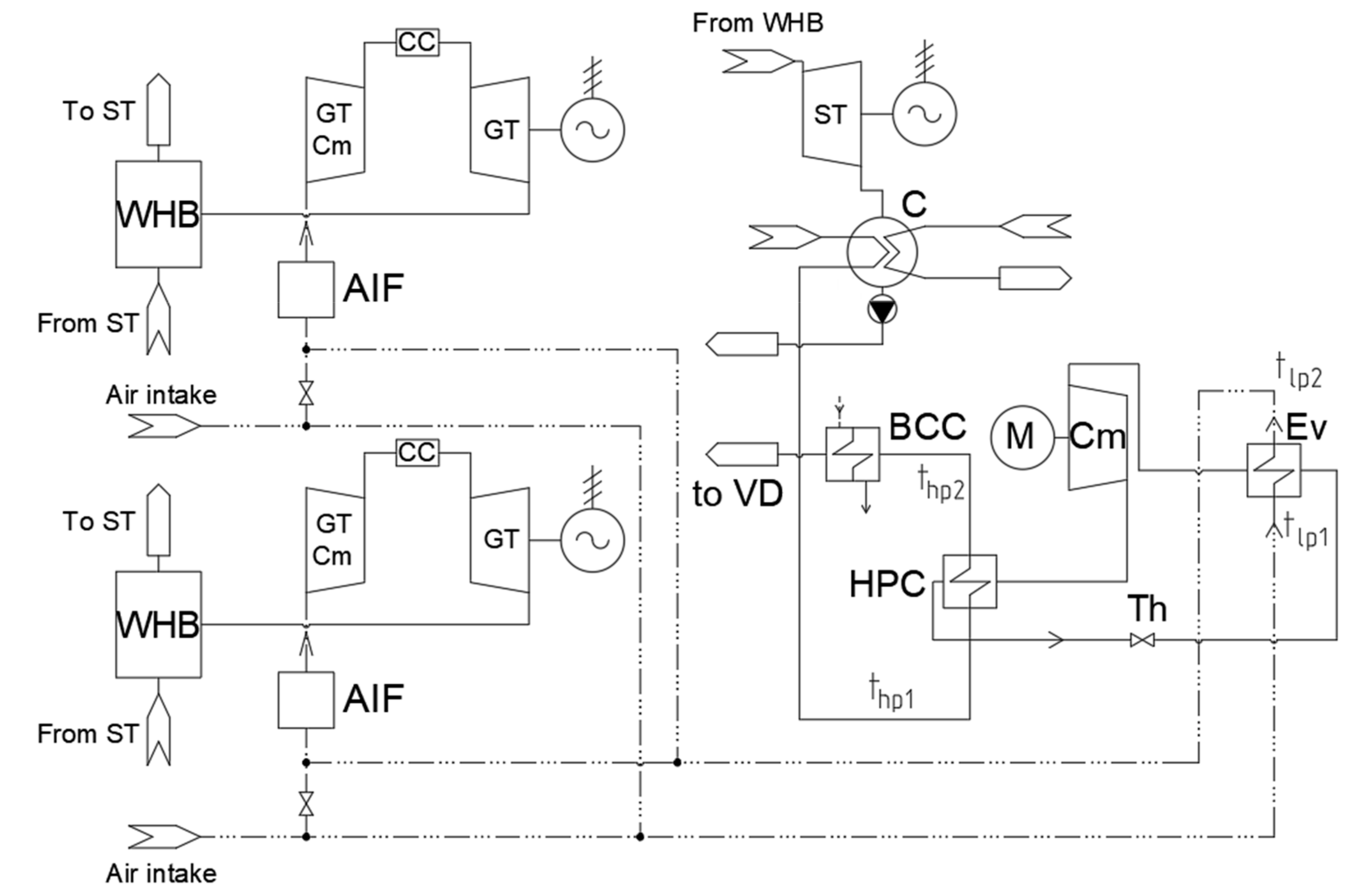
Figure 7.
The scheme of air cooling and heating make-up water in summer time using a simple scheme VCHP. AIF—air intake filter; CC—combustion chamber; GT Cm—GT compressor.
Figure 7.
The scheme of air cooling and heating make-up water in summer time using a simple scheme VCHP. AIF—air intake filter; CC—combustion chamber; GT Cm—GT compressor.

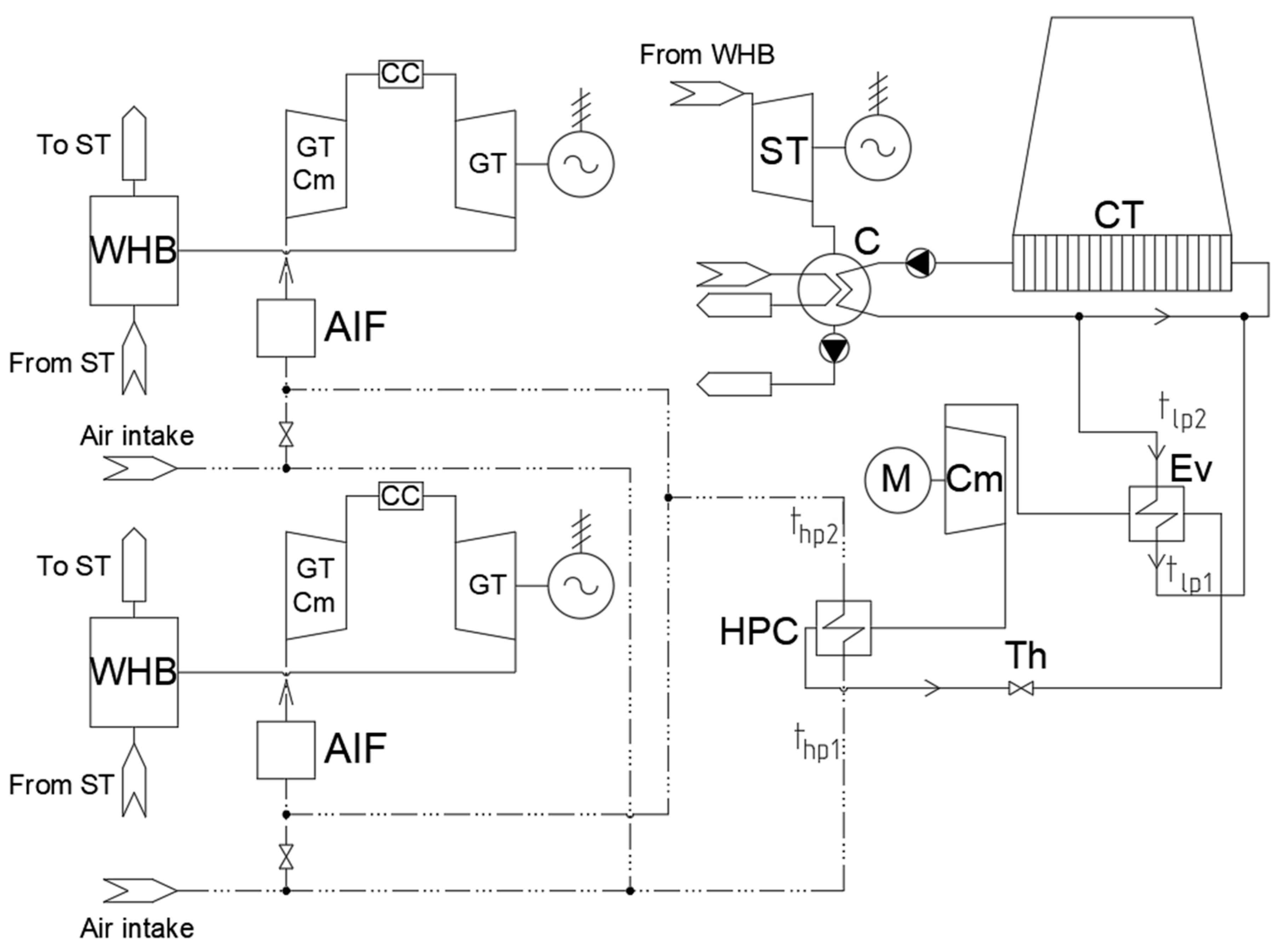
Figure 8.
The scheme of air heating before AIF’s intake in winter time using a simple scheme VCHP.

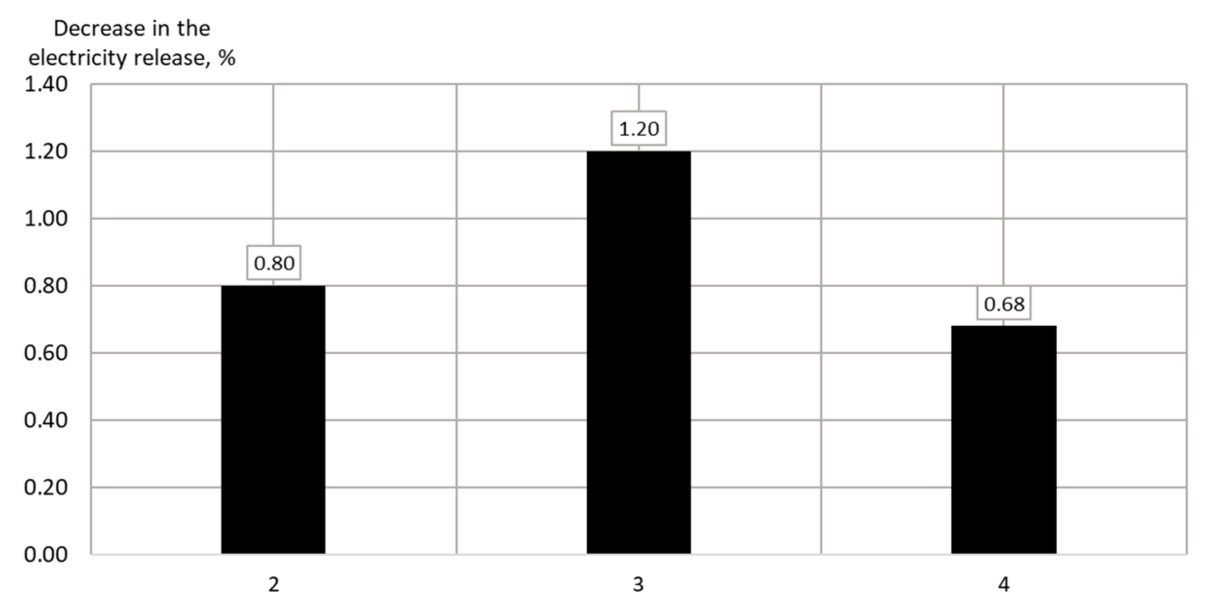
Figure 9.
Decrease in the electricity release with integrated HPUs.

Figure 10.
Decrease in the electricity release with integrated HPUs.

Figure 11.
Influence of VCHP on the heat and electricity release.

Figure 12.
Influence of VCHP capacity on the economic effect of integrating VCHP for make-up water heating.
Figure 12.
Influence of VCHP capacity on the economic effect of integrating VCHP for make-up water heating.


Table 1.
Technical characteristics of heat pumps of “Teplosibmash” [24].
Table 1.
Technical characteristics of heat pumps of “Teplosibmash” [24].
| Parameter | Value | |
|---|---|---|
| Absorption Heat Pump (AHP) Type | AHP-P | AHP2-P |
| Heating capacity, kW | 850–10,000 | 600–7200 |
| Temperature of cooled water, °C | 30/25 | 30/25 |
| Temperature of heated water, °C | 30/80 | 30/55 |
| Heating agent | Steam | |
| Heating steam pressure, MPa | 0.4 | 0.7 |
| Transformation ratio, - | 1.75 | 2.25 |
Table 2.
Comparison of calculated in United Cycle (UC) and control parameters.
| Parameter | Model Data | Control Data | Deviation, % |
|---|---|---|---|
| Power at the terminals of the gas turbine (GT) generator, MW | 155.3 | 155.3 | 0.00 |
| Gas turbine exhausted gas temperature, °C | 537 | 537 | 0.00 |
| Gas turbine exhausted gas mass flow rate, kg/s | 509 | 509 | 0.00 |
| High-pressure steam mass flow rate, t/h | 231.2 | 234.6 | 1.45 |
| High-pressure steam temperature, °C | 506.5 | 512.84 | 1.24 |
| High-pressure steam pressure, 10−1 MPa | 38.61 | 38.61 | 0.00 |
| Low-pressure steam mass flow rate, t/h | 39.0 | 40.4 | 3.47 |
| Low-pressure steam temperature, °C | 209.6 | 207.95 | 0.79 |
| Low-pressure steam pressure, 10−1 MPa | 4.1 | 4.1 | 0.00 |
| Power at the terminals of the steam turbine (ST) generator, MW | 58.94 | 61.52 | 4.19 |
| Steam mass flow rate in the condenser, t/h | 161.64 | 165.13 | 2.11 |
| Pressure in the condenser, 10−1 MPa | 0.033 | 0.034 | 2.94 |
| Steam pressure in network heater NH-1, 10−1 MPa | 0.856 | 0.863 | 0.81 |
| Steam mass flow rate to NH-1, t/h | 106.38 | 107.62 | 1.15 |
| Heat load of NH-1, MW | 67.64 | 68.34 | 1.02 |
| Return network water (RNW) temperature, °C | 89.8 | 90.0 | 0.22 |
| RNW mass flow rate, t/h | 2933 | 2933 | 0.00 |
| Feed water mass flow rate at the intake of WHB, t/h | 270.2 | 275.0 | 1.75 |
Table 3.
Low-potential heat sources (LPHS) at CCGTs.
| LPHSs of Cooling Systems | LPHSs of Waste Systems |
|---|---|
| Equipment oil cooling system | Purging the water recycling system |
| Condenser cooling system | Waste gases |
| Turbine oil cooling system | Purging drums |
| Equipment air cooling system | Sewer drains |
Table 4.
Positive and negative aspects of using circulating water as a LPHS for HPUs.
| Positive Aspects | Negative Aspects |
|---|---|
| High heat-transfer coefficient | Dependence on the operating mode of the main equipment of a CHPP |
| Low costs for intake and transport of a heat carrier in the case of heating make-up or RNW | Direct relationship with the ST mode |
| Rather high evaporation temperature of a HPU working fluid | Complexity of a HPU load regulation to maintain standard operating modes |
| Large range of variation of the heat carrier flow | |
| Reducing the cost of driving circulating water pumps |
Table 5.
Positive and negative aspects of using air at the intake of a gas turbine unit as a LPHS.
| Positive Aspects | Negative Aspects |
|---|---|
| High heat transfer coefficient | Dependence on the operating mode of the gas turbine |
| Rather high evaporation temperature of a HPU working fluid | Complexity of a HPU regulation to maintain the air temperature level |
| Reduced GT compressor drive costs | Small range of variation of the heat carrier flow |
| Increasing the capacity of the GT (Figure 3) |
Table 6.
The results of using HPUs of various types for heating RNW in the winter mode with low heating loads.
Table 6.
The results of using HPUs of various types for heating RNW in the winter mode with low heating loads.
| Parameter | Value | ||||||
|---|---|---|---|---|---|---|---|
| HPU Type and Power | Initial Mode | VCHP with a RHE and a Sc, 20 MW | AHP2-P, 20 MW | AHP-P, 20 MW | VCHP with a RH and a Sc, 40 MW | AHP2-P, 40 MW | AHP-P, 40 MW |
| Mode number | 1 | 2 | 3 | 4 | 5 | 6 | 7 |
| RNW temp. before/after HPU, °C | 61.1/61.1 | 61.1/64.1 | 61.1/64.1 | 61.1/64.1 | 61.1/67.0 | 61.1/67.0 | 61.1/67.0 |
| Energy conv. coef. (transform. ratio), - | - | 3.70 | 2.25 | 1.75 | 3.54 | 2.25 | 1.75 |
| LPHS mass flow rate, t/h | - | 1674.42 | 1405.85 | 1117.38 | 2743.36 | 2515.91 | 2048.62 |
| Tot. own needs, MW | 8.94 | 16.96 | 9.48 | 9.48 | 25.07 | 9.58 | 9.55 |
| Heat release, MW | 312.15 | 312.15 | 312.15 | 312.27 | 312.27 | 312.38 | 312.38 |
| Elec. release, MW | 432.62 | 427.01 | 428.93 | 431.11 | 421.30 | 425.95 | 430.39 |
Table 7.
Winter modes simulation results of using HPUs for heating make-up water with a flow rate of 800 t/h.
Table 7.
Winter modes simulation results of using HPUs for heating make-up water with a flow rate of 800 t/h.
| Parameter | Value | |||
|---|---|---|---|---|
| HPU Type and Power | Initial Mode | VCHP with a RHE and a Sc, 20 MW | AHP2-P, 20 MW | AHP-P, 20 MW |
| Mode number | 1 | 2 | 3 | 4 |
| Make-up wat. temp. before/after HPU, °C | 21.5/21.5 | 21.5/43.0 | 21.5/43.0 | 21.5/43.0 |
| Energy conv. coef. (transform. ratio), - | - | 7.39 | 2.25 | 1.75 |
| LPHS mass flow rate, t/h | - | 2439.09 | 1770.16 | 1418.04 |
| Tot. own needs, MW | 8.94 | 12.88 | 9.14 | 9.11 |
| Heat release, MW | 312.15 | 312.27 | 312.38 | 312.27 |
| Elec. release, MW | 432.62 | 429.16 | 427.45 | 429.67 |
Table 8.
Winter modes simulation results of using HPUs for heating make-up water with a flow rate of 1500 t/h.
Table 8.
Winter modes simulation results of using HPUs for heating make-up water with a flow rate of 1500 t/h.
| Parameter | Value | ||||||
|---|---|---|---|---|---|---|---|
| HPU Type and Power | Initial Mode | VCHP with a RHE and a Sc, 20 MW | AHP-P 20 MW | VCHP with a RHE and a Sc, 25 MW | VCHP with a RHE and a Sc, 30 MW | VCHP with a RHE and a Sc, 35 MW | VCHP with a RHE and a Sc, 40 MW |
| Mode number | 1 | 2 | 3 | 4 | 5 | 6 | 7 |
| Make-up wat. temp. before/ after HPU, °C | 13.5/13.5 | 13.5/42.2 | 13.5/42.2 | 13.5/49.4 | 13.5/56.6 | 13.5/63.8 | 13.5/70.9 |
| Energy conv. coef. (transform. ratio), - | - | 7.89 | 1.75 | 6.60 | 5.70 | 5.01 | 4.48 |
| LPHS mass flow rate, t/h | - | 4418.24 | 1675.74 | 5366.18 | 6446.54 | 7530.69 | 8354.19 |
| Tot. own needs, MW | 8.88 | 12.81 | 9.14 | 14.6 | 16.71 | 19.14 | 21.85 |
| Heat release, MW | 373.13 | 381.23 | 361.09 | 382.38 | 383.55 | 384.50 | 385.20 |
| Elec. release, MW | 428.49 | 424.55 | 428.23 | 422.77 | 420.67 | 418.24 | 415.54 |
| GT efficiency, % | 33.29 | 33.29 | 33.29 | 33.29 | 33.29 | 33.29 | 33.29 |
| CCGT efficiency, % | 44.47 | 44.06 | 44.44 | 43.88 | 43.66 | 43.41 | 43.13 |
Table 9.
Results of using VCHPs for heating the intake air for winter modes.
| Parameter | Value | |||||
|---|---|---|---|---|---|---|
| Air Heating Device | AIS | VCHP sim.sch., 3.05 MW | AIS | VCHP sim.sch., 4.05 MW | AIS | VCHP sim.sch., 5.04 MW |
| Mode number | 1 | 2 | 3 | 4 | 5 | 6 |
| Outside air temperature, °C | −2 | −2 | −2 | −2 | −2 | −2 |
| Air temperature after heating, °C | +4 | +4 | +6 | +6 | +8 | +8 |
| Total air mass flow rate, t/h | 1788.67 | 1821.58 | 1767.91 | 1811.52 | 1747.28 | 1801.45 |
| Air mass flow rate through HPU, t/h | - | 223.96 | - | 297.12 | - | 369.55 |
| Required heat release from HPU, MW | - | 3.05 | - | 4.05 | - | 5.04 |
| Energy conv. coef., - | - | 6.04 | - | 6.04 | - | 6.04 |
| LPHS mass flow rate, t/h | - | 413.67 | - | 559.36 | - | 709.37 |
| Tot. own needs, MW | 8.65 | 10.31 | 8.61 | 10.76 | 8.56 | 11.20 |
| Heat release, MW | 312.01 | 312.00 | 311.97 | 311.95 | 311.96 | 311.93 |
| Elec. release by GT, MW | 139.56 | 155.15 | 132.90 | 153.46 | 126.36 | 151.78 |
| Elec. release, MW | 384.45 | 416.84 | 369.77 | 412.61 | 355.54 | 408.40 |
| Increment of electricity release, % | - | 8.43 | - | 11.59 | - | 14.87 |
| GT efficiency, % | 30.42 | 33.35 | 29.43 | 33.34 | 28.43 | 33.32 |
| CCGT efficiency, % | 41.89 | 44.80 | 40.94 | 44.82 | 40.00 | 44.82 |
| CFHU, % | 80.51 | 83.09 | 80.08 | 83.49 | 79.66 | 83.87 |
Table 10.
Summer modes simulation results of using VCHPs for cooling the intake air.
| Parameter | Value | |||
|---|---|---|---|---|
| HPU Type and Power | Initial Mode | VCHP sim.sch., 12.45 MW | VCHP with a RHE, 12.45 MW | VCHP with a RHE and a Sc, 12.26 MW |
| Mode number | 1 | 2 | 3 | 4 |
| Outside air temperature, °C | +15 | +15 | +15 | +15 |
| Air temperature after heating, °C | +15 | +5 | +5 | +5 |
| Total air mass flow rate, t/h | 1760.82 | 1816.56 | 1816.56 | 1816.56 |
| Air mass flow rate through HPU, t/h | - | 1816.56 | 1816.56 | 1816.56 |
| Required evaporator capacity, MW | - | 10.19 | 10.19 | 10.19 |
| Energy conv. coef., - | - | 5.52 | 5.54 | 6.04 |
| Tot. own needs, MW | 8.80 | 15.18 | 15.16 | 14.57 |
| Heat release, MW | 256.86 | 256.73 | 256.73 | 256.73 |
| Elec. release, MW | 405.16 | 418.44 | 418.46 | 419.05 |
| Increment of electricity release, % | - | 3.28 | 3.28 | 3.43 |
| GT efficiency, % | 33.23 | 33.35 | 33.35 | 33.35 |
| CCGT efficiency, % | 46.15 | 45.22 | 45.22 | 45.29 |
| CFHU, % | 79.99 | 77.41 | 77.41 | 77.47 |
Table 11.
Winter mode simulation results of using HPUs for heating make-up water with a flow rate of 1500 t/h.
Table 11.
Winter mode simulation results of using HPUs for heating make-up water with a flow rate of 1500 t/h.
| Parameter | Value | |||||
|---|---|---|---|---|---|---|
| HPU Type and Power | Initial Mode | VCHP with a RHE and a Sc, 20 MW | VCHP with a RHE and a Sc, 25 MW | VCHP with a RHE and a Sc, 30 MW | VCHP with a RHE and a Sc, 35 MW | VCHP with a RHE and a Sc, 40 MW |
| Mode number | 1 | 2 | 4 | 5 | 6 | 7 |
| The method with a fixed specific fuel consumption for the heat release | ||||||
| Consumption of ref. fuel for electricity release, t r.f./h | 62.15 | 61.08 | 60.92 | 60.77 | 60.64 | 60.55 |
| Consumption of ref. fuel for heat release, t r.f./h | 49.41 | 50.48 | 50.63 | 50.79 | 50.91 | 51.01 |
| Specific consumption of ref. fuel for electricity release, g. r.f./(kW∙h) | 145.05 | 143.86 | 144.11 | 144.46 | 145.00 | 145.72 |
| Specific consumption of ref. fuel for heat release, kg. r.f./MW | 132.42 | |||||
| “Model 15506” | ||||||
| Consumption of ref. fuel for electricity release, t r.f./h | 71.72 | |||||
| Consumption of ref. fuel for heat release, t r.f./h | 39.84 | |||||
| Specific consumption of ref. fuel for electricity release, g. r.f./(kW∙h) | 167.37 | 168.92 | 169.63 | 170.48 | 171.47 | 172.59 |
| Specific consumption of ref. fuel for heat release, kg. r.f./MW | 106.78 | 104.51 | 104.20 | 103.88 | 103.62 | 103.43 |
Table 12.
Winter mode simulation results of using VCHPs for heating the intake air.
| Parameter | Value | |||||
|---|---|---|---|---|---|---|
| Air Heating Device | AIS | VCHP sim.sch., 3.05 MW | AIS | VCHP sim.sch., 4.05 MW | AIS | VCHP sim.sch., 5.04 MW |
| Mode number | 1 | 2 | 3 | 4 | 5 | 6 |
| Air temperature after heating, °C | +4 | +4 | +6 | +6 | +8 | +8 |
| Economic effect, 103 $/(MW∙quarter) | - | 313.08 | - | 312.21 | - | 309.64 |
| The method with a fixed specific fuel consumption for the heat release | ||||||
| Consumption of ref. fuel for electricity release, t r.f./h | 64.94 | 66.42 | 63.26 | 65.28 | 61.61 | 64.19 |
| Consumption of ref. fuel for heat release, t r.f./h | 41.31 | 41.31 | 41.31 | 41.31 | 41.31 | 41.30 |
| Specific consumption of ref. fuel for electricity release, g. r.f./(kW∙h) | 168.91 | 159.34 | 171.08 | 158.22 | 173.28 | 157.18 |
| Specific consumption of ref. fuel for heat release, kg. r.f./MW | 132.42 | |||||
| “Model 15506” | ||||||
| Consumption of ref. fuel for electricity release, t r.f./h | 68.30 | 69.26 | 67.22 | 68.52 | 66.16 | 67.82 |
| Consumption of ref. fuel for heat release, t r.f./h | 37.95 | 38.48 | 37.35 | 38.07 | 36.76 | 37.68 |
| Specific consumption of ref. fuel for electricity release, g. r.f./(kW∙h) | 177.67 | 166.15 | 181.80 | 166.07 | 186.08 | 166.06 |
| Specific consumption of ref. fuel for heat release, kg. r.f./MW | 121.63 | 123.32 | 119.71 | 122.03 | 117.82 | 120.78 |
Table 13.
Summer modes simulation results of using VCHPs for cooling the intake air.
| Parameter | Value | |||
|---|---|---|---|---|
| HPU Type and Power | Initial Mode | VCHP sim.sch., 12.45 MW | VCHP with a RHE, 12.45 MW | VCHP with a RHE and a Sc, 12.26 MW |
| Mode number | 1 | 2 | 3 | 4 |
| Economic effect, 103 $/(MW∙quarter) | - | 16.83 | 16.93 | 20.23 |
| The method with a fixed specific fuel consumption for the heat release | ||||
| Consumption of ref. fuel for electricity release, t r.f./h | 67.64 | 73.14 | 73.14 | 73.14 |
| Consumption of ref. fuel for heat release, t r.f./h | 34.01 | 34.00 | 34.00 | 34.00 |
| Specific consumption of ref. fuel for electricity release, g. r.f./(kW∙h) | 166.95 | 174.79 | 174.78 | 174.54 |
| Specific consumption of ref. fuel on heat release, kg. r.f./MW | 132.42 | |||
| “Model 15506” | ||||
| Consumption of ref. fuel for electricity release, t r.f./h | 65.35 | 68.87 | 68.87 | 68.87 |
| Consumption of ref. fuel for heat release, t r.f./h | 36.30 | 38.26 | 38.26 | 38.26 |
| Specific consumption of ref. fuel for electricity release, g. r.f./(kW∙h) | 161.29 | 164.60 | 164.59 | 164.36 |
| Specific consumption of ref. fuel for heat release, kg. r.f./MW | 141.34 | 149.04 | 149.04 | 149.04 |
Publisher’s Note: MDPI stays neutral with regard to jurisdictional claims in published maps and institutional affiliations. |
© 2021 by the authors. Licensee MDPI, Basel, Switzerland. This article is an open access article distributed under the terms and conditions of the Creative Commons Attribution (CC BY) license (https://creativecommons.org/licenses/by/4.0/).
Share and Cite
MDPI and ACS Style
Sergeev, V.; Anikina, I.; Kalmykov, K. Using Heat Pumps to Improve the Efficiency of Combined-Cycle Gas Turbines. Energies 2021, 14, 2685. https://0-doi-org.brum.beds.ac.uk/10.3390/en14092685
AMA Style
Sergeev V, Anikina I, Kalmykov K. Using Heat Pumps to Improve the Efficiency of Combined-Cycle Gas Turbines. Energies. 2021; 14(9):2685. https://0-doi-org.brum.beds.ac.uk/10.3390/en14092685
Chicago/Turabian StyleSergeev, Vitaly, Irina Anikina, and Konstantin Kalmykov. 2021. "Using Heat Pumps to Improve the Efficiency of Combined-Cycle Gas Turbines" Energies 14, no. 9: 2685. https://0-doi-org.brum.beds.ac.uk/10.3390/en14092685
Note that from the first issue of 2016, this journal uses article numbers instead of page numbers. See further details here.