
Inertia Control Strategy of DFIG-Based Wind Turbines Considering Low-Frequency Oscillation Suppression


College of Energy and Electrical Engineering, Hohai University, Nanjing 211100, China
*
Author to whom correspondence should be addressed.
Energies 2022, 15(1), 29; https://0-doi-org.brum.beds.ac.uk/10.3390/en15010029
Submission received: 15 November 2021
/
Revised: 8 December 2021
/
Accepted: 18 December 2021
/
Published: 21 December 2021
(This article belongs to the Special Issue Frequency Control of AC/DC Hybrid Power Grid considering Large-Scale New Energy Integration)
Abstract
:It has become a basic requirement for wind turbines (WTs) to provide frequency regulation and inertia support. The influence of WTs on the low-frequency oscillation (LFO) of the system will change after adopting inertia control methods. This paper intends to investigate and compare in detail the IC effects on LFO characteristics in two systems with different structures. First, the mechanism of inertia control of doubly fed induction generator (DFIG)-based WTs is analyzed. Then, the small-signal analysis method and modal analysis method are used to study the influence of the inertia control on the LFO characteristics based on the two-machine infinite-bus system and the four-machine two-area system, respectively. The difference in impact rules of IC on LFO is compared in detail. Finally, considering that the inertia control might worsen the LFO in some systems, an improved inertia control strategy of DFIG-based WTs is proposed to suppress the LFO. The simulation results demonstrate that, in systems with different structures, the impact rules of the inertia control parameters on LFO are different. With the improved inertia control strategy, DFIG-based WTs can suppress the LFO of the system and provide inertia support for the system.
1. Introduction
At present, with the increasing wind power penetration level, the leading wind power developed countries and regions in the world have issued grid connected guidelines to put forward requirements on the inertia and frequency regulation capability of wind turbines (WTs) [1,2,3], and encourage WTs to actively participate in system frequency regulation through market mechanisms. The virtual inertia control (IC) technology is one of the hot research directions of WTs participating in system frequency regulation and providing inertia support. Referring to the external characteristics of synchronous generators, the virtual IC of DFIG-based WTs adds the control link related to system frequency in the control of the power converter to achieve inertia support for the system [4,5,6,7,8].
Early studies mainly focused on improving the dynamic characteristics of system frequency by the IC of WTs. However, follow-up research has revealed new aspects about integrating IC of DFIG-based WTs. The integration of IC of DFIG-based WTs allows the speed of WTs to be coupled with the system frequency, which changes the dynamic characteristics of synchronous generators in electromechanical transient time scale. Accordingly, the integration of IC of DFIG-based WTs will change the low-frequency oscillation (LFO) characteristics of the system and affect the safe and stable operation of the power system [9,10,11,12]. At present, researchers have conducted research on the influence of the integration of the IC of DFIG-based WTs on the LFO characteristics of the system, but no unified and exact conclusion has been obtained.
Based on time-domain simulation and modal analysis, the influence of IC on the inter-area oscillation mode of the system is studied in [13]. The results show that the IC of WTs is beneficial to suppress the inter-area oscillation of the system. It is pointed out in [14] that when IC is adopted to WTs, the damping ratio of the system can be significantly increased. Moreover, the closer the WT is to the synchronous generator, the greater the increase of system damping ratio is.
However, it is pointed out in [15,16] that a new oscillation mode, which poses a threat to the small-signal stability of the system, is induced by the IC of WTs. Therefore, damping controllers for the WTs are designed in [15,16]. Moreover, the effects of two different IC methods on small-signal stability are studied in [17]. Study results show that the two IC methods reduce the small-signal stability of the system. Meanwhile, the reduction of the small-signal stability is further enhanced by adopting more complicated two-loop IC methods.
In [18], the internal voltage motion equation of the synchronous generator is introduced into the modeling of DFIG-based WTs with IC. Based on this model, the influence law and mechanism of IC parameters on the electromechanical oscillation damping of the synchronous generator are studied by using the damping torque analysis method. It is pointed out in [19] that the smaller the proportional-integral (PI) parameters of the phase-locked loop (PLL), the smaller the degree of the IC state variables participating in inter-area oscillation mode, and the greater the damping ratio of inter-area oscillation mode. In [20], the influence on the small-signal stability with different wind power penetration levels, wind farm (WF) connection impedance values, and ancillary control schemes are studied by eigenvalue analysis and verified by time-domain simulations.
In addition, there has been some research on the power oscillation damping controllers of WTs to suppress the LFO of the system. The structure of the power oscillation damping controllers of WTs is mostly similar to that of the conventional power system stabilizer (PSS) [15,16,21,22,23,24]. Aside from the damping controllers whose structure is similar to that of the PSS, some researchers have proposed different damping controllers of WTs. In [25], a damping controller is proposed to suppress the inter-area oscillation of the system by scaling down the oscillatory component of the dominant oscillation mode and adding the inverse of this scaled oscillatory component to the reference power of the WF. In [26], a design scheme of damping controller for DFIG-based WTs based on fuzzy control is proposed, and the bat optimization algorithm is used to optimize the control parameters of the controller. A WF level LFO damping controller (LFODC), consisting of index analyzer, feedback selection, model estimator, and linear quadratic Gaussian controller, is proposed in [27]. With the index analyzer and model estimator, the proposed LFODC help adapt to operating condition variations of power systems, showing a better damping performance. In [28], a novel enhanced adaptive phasor power oscillation damping (EAPPOD) controller is proposed, which consists of signal decomposition block, adaptive latency compensation block, and LFO suppression block. Moreover, the EAPPOD controller can compensate time-varying data transmission latencies between phasor measurement unit sites and the control center as well as suppress the LFO.
At present, most studies on the influence of the IC on the LFO characteristics of the system are based on their respective system models. Few analyze whether the impacts of IC on the LFO characteristics are related to system structures and provide a comparison of such impacts in different systems. Refs. [18,19] demonstrated proposed control strategies on both a two-machine infinite-bus system and a four-machine two-area system. However, the impacts of IC on the LFO characteristics were not the main focus in these works, and detailed discussions were not provided. In this paper, we investigate and compare in detail the IC effects on LFO characteristics in two systems with different structures. Specifically, the IC is implemented and compared on a two-machine infinite-bus system and a four-machine two-area system. Based on the IC of DFIG-based WTs, the different impact rules of the IC parameters on LFO characteristics in systems with different structures are investigated and compared. Further, since the integration of the IC might worsen the LFO in some systems, an improved IC strategy of DFIG-based WTs is proposed to suppress the LFO. The proposed improved IC strategy can enhance the inertia support capability of DFIG-based WTs and suppress the LFO.
The rest of this paper is organized as follows. Section 2 introduces the IC mechanism of DFIG-based WTs. Section 3 presents the modal and simulation analysis of the influence of IC on the LFO characteristics. Section 4 proposes an improved IC strategy of DFIG-based WTs considering LFO suppression and the simulation. Section 5 draws conclusions.
2. Inertia Control of DFIG-Based Wind Turbine
The inertia response of the synchronous generator is essentially the process that the synchronous generator adjusts its rotor speed gradually under the drive of unbalanced torque, and finally realizes the rebalancing of input mechanical torque and output electromagnetic torque, as well as the synchronous operation with the power grid again. The external performance of this process is that the synchronous generator stores or releases the rotor kinetic energy according to the system frequency changes, so as to change its own output electromagnetic torque.
The common virtual IC of DFIG-based WTs imitates the external characteristics of inertia response of synchronous generators and introduces the control link related to system frequency into the active power reference value of the original maximum power point tracking (MPPT) control strategy. Therefore, IC associates the output electromagnetic power of the DFIG-based WT with the system frequency, that is, the DFIG-based WT can adjust its own output electromagnetic power according to the change of system frequency.
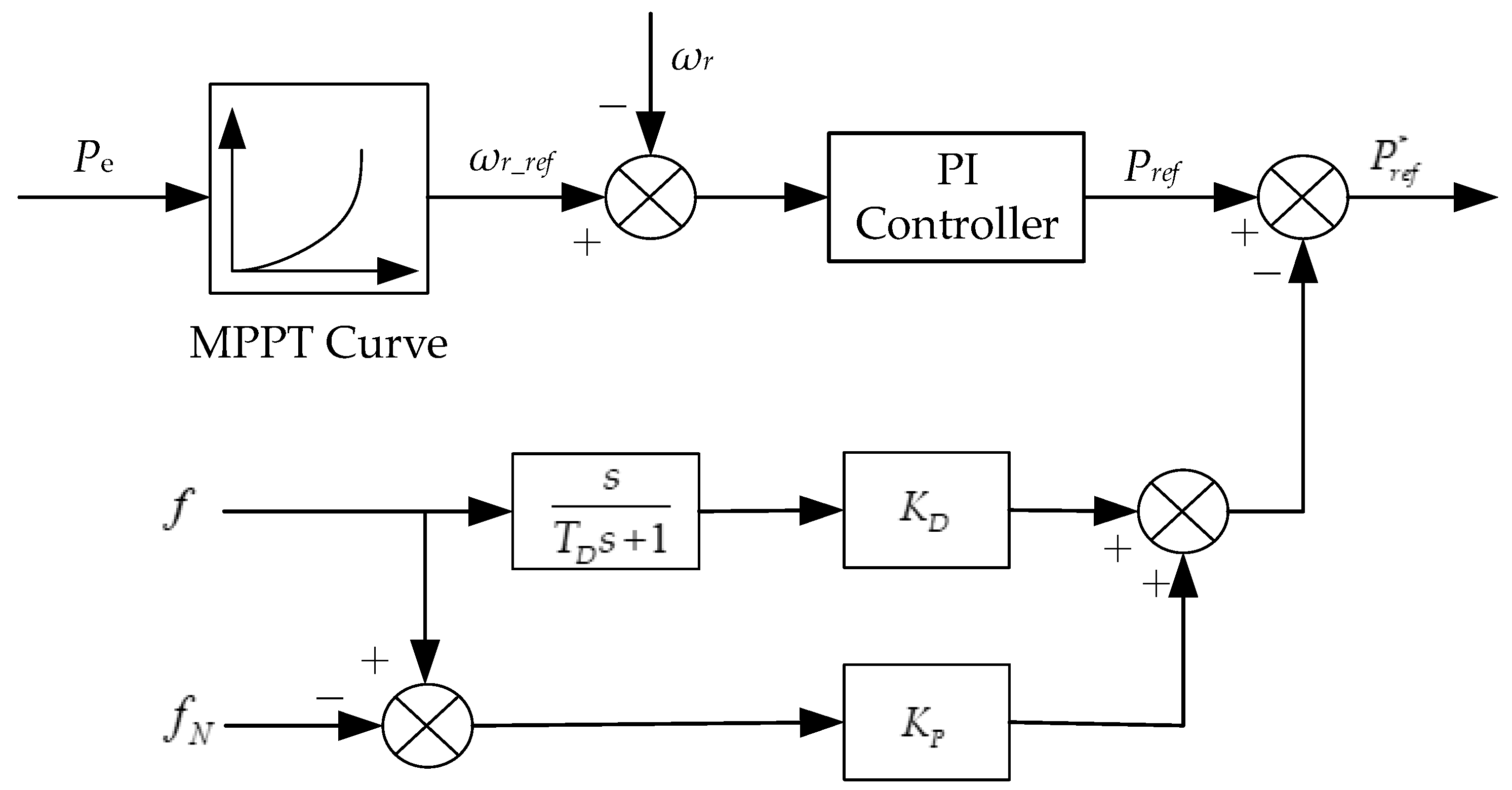
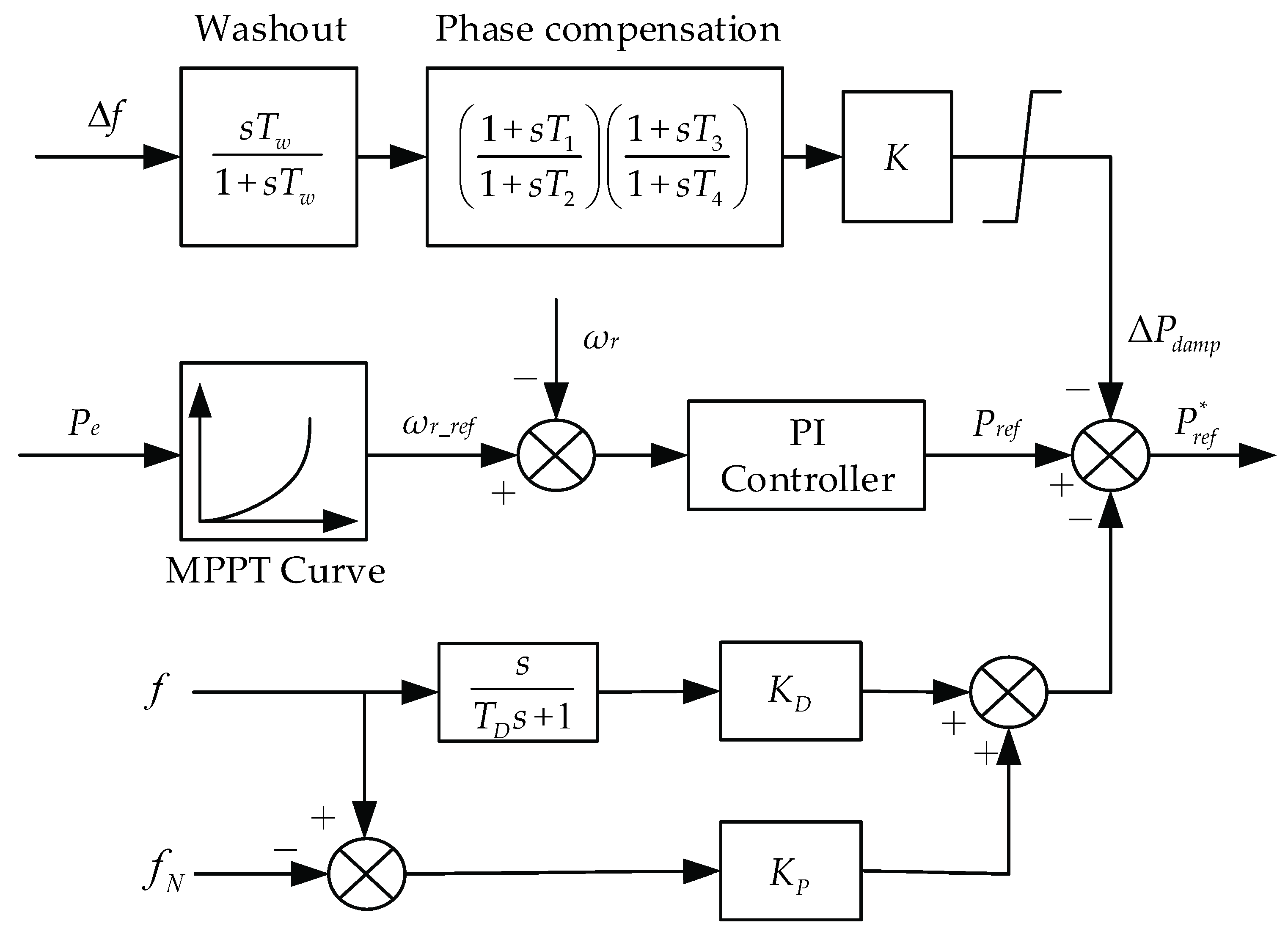
Figure 1 depicts the active power control structure of DFIG-based WTs with IC. The inertia response of synchronous generators is mainly reflected in the initial stage of system frequency change, when the amplitude of frequency change is small and the rate of frequency change is large, so the change of output electromagnetic power of a synchronous generator is approximately proportional to the rate of system frequency change. Moreover, the damping effect of synchronous generators is usually expressed by the gain of frequency deviation. Referring to the relationship between the change of output electromagnetic power and system frequency in the inertia response process of synchronous generators, the expression of output electromagnetic power of DFIG-based WTs under IC can be expressed as follows:
where is the active power reference value of DFIG-based WTs under IC; is the active power reference value of DFIG-based WTs under the original MPPT control strategy; is the gain of frequency differential control; is the gain of frequency deviation control; is a differential operator; is the measured value of system frequency; is the rated value of system frequency; is the differential time constant. In order to realize the differential of frequency, should be a very small value, which is 0.01 s in this paper.
According to Equation (1), the active power control structure of DFIG-based WTs under IC can be obtained, as shown in Figure 1.
3. Influence of the Integration of Inertia Control on the Low-Frequency Oscillation Characteristics of Systems
The low-frequency oscillation with inertia control of DFIGs in the two-machine infinite-bus system and four-machine two-area system are studied. The influence of the IC on the LFO characteristics of the two-machine infinite-bus system is studied by the small-signal analysis method and modal analysis method. Moreover, the modal analysis method and the time domain simulation method are used to analyze the influence of the integration of IC on the LFO characteristics of the four-machine two-area system.
3.1. Two-Machine Infinite-Bus System
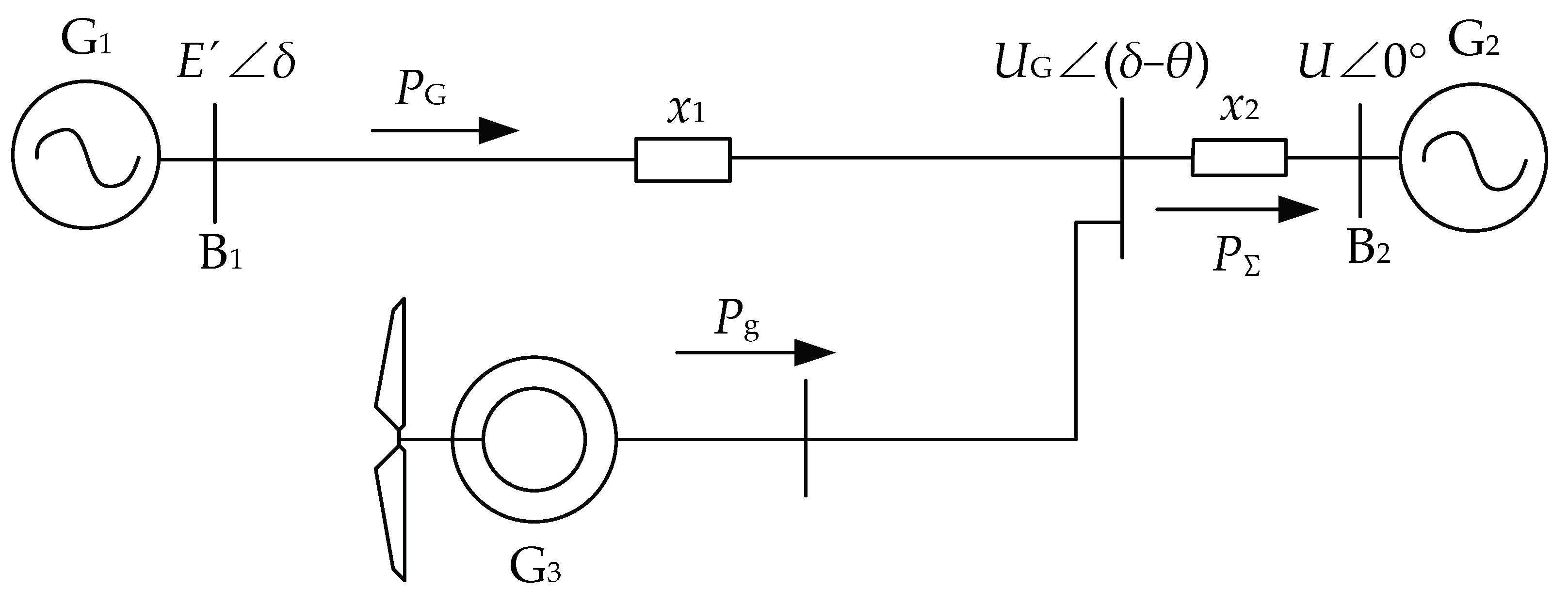
Firstly, based on the two-machine infinite-bus system [19] as shown in Figure 2, the small-signal analysis method is used to study the influence of the IC of DFIG-based WTs on the LFO characteristics of the system.
In Figure 2, G1 and G2 are synchronous generators, G3 is a DFIG-based WF, and G2 is the slack generator. is the voltage of point of common coupling (PCC), is the q-axis transient potential of G1, U is the terminal voltage of G2, is the phase angle difference between and , is the phase angle difference between and U, that is, the power angle of G1. and are reactance parameters of transmission line, respectively.
Assuming that the mechanical power is constant, the swing equation of the synchronous generator is linearized near the operating point, and the following equation can be obtained:
where and are the inertia time constant and damping coefficient of G1, respectively; is the output electromagnetic power of G1.
According to the power balance relationship, the following equation can be obtained:
where is the total output electromagnetic power of G1 and G3; is the electromagnetic power of the G3.
and can be expressed as:
In order to simplify the analysis, the change of generator node voltage is ignored, and the voltage at the PCC is assumed to be constant. The linearization of Equation (3) can be expressed as
where and are the initial value of and , respectively.
Assuming that the PLL can track the system frequency without error, the system frequency output by the PLL can be expressed by the speed of synchronous generator G1. When the IC strategy of DFIG-based WT is adopted, the change of output electromagnetic power caused by the system frequency fluctuation can be expressed as
where is the electric angular velocity of G1.
Combining Equations (6) and (7), the following equation can be obtained:
where .
According to Equations (5) and (8), the following equation can be obtained:
Combining Equations (2) and (9), the following equation can be obtained:
where ; ; .
According to Equation (10), the eigenvalues and corresponding damping ratios of the system are obtained as follows:
It can be seen from Equation (10) that the frequency differential control link in the IC strategy of DFIG-based WTs increases the inertia time constant of the system equivalently, while the frequency deviation control link increases the damping of the system equivalently. From Equations (11) and (12), it is found that the frequency differential control link in the IC will make the eigenvalue of the system move to the right in the complex plane and reduce the corresponding oscillation damping ratio. So, the frequency differential control link is not conducive to the suppression of power oscillation in the system. Moreover, the larger the gain KD is, the closer the eigenvalue of the system is to the imaginary axis, and the smaller the oscillation damping ratio is. In other words, the larger the gain KD is, the greater the negative effect of the frequency differential control link on the LFO of the system is. However, the frequency deviation control link in the IC will make the eigenvalue of the system move to the left in the complex plane and increase the corresponding damping ratio. Therefore, the frequency deviation control link is beneficial to suppress the LFO of the system. In addition, with the increase of the gain KP, the eigenvalue of the system moves to the left in the complex plane, and the oscillation damping ratio increases, which indicates that the larger the gain KP is, the better is the performance of the LFO suppression of the LFO. Above all, from the small-signal analysis, it can be found that whether the IC of DFIG-based WTs is conducive to the suppression of LFO is related to the selection of control parameters, and no definite conclusions can be drawn.
Furthermore, the modal analysis method is used to study the influence of the IC on the LFO characteristics of the two-machine infinite-bus system. The two-machine infinite-bus system shown in Figure 2 is constructed in DIgSILENT software. In the model, the parameters of synchronous generator G1 are the parameters of synchronous generator G1 in the classical four-machine two-area system model [29]. The total output active power of the WF G3, which is composed of 140 DFIG-based WTs with the active power output of 5 MW, is 700 MW. The parameters of a single DFIG-based WT are set as follows.
The rated capacity is 5.8 MVA; the rated terminal voltage is 6.3 kV; the inherent inertia time constant of DFIG rotor is 0.423 s. The other generator parameters in per unit on the rated MVA and kV base are stator leakage inductance , rotor leakage inductance , excitation inductance
The parameters of the lines in per unit on 100 MVA, 230 kV base are
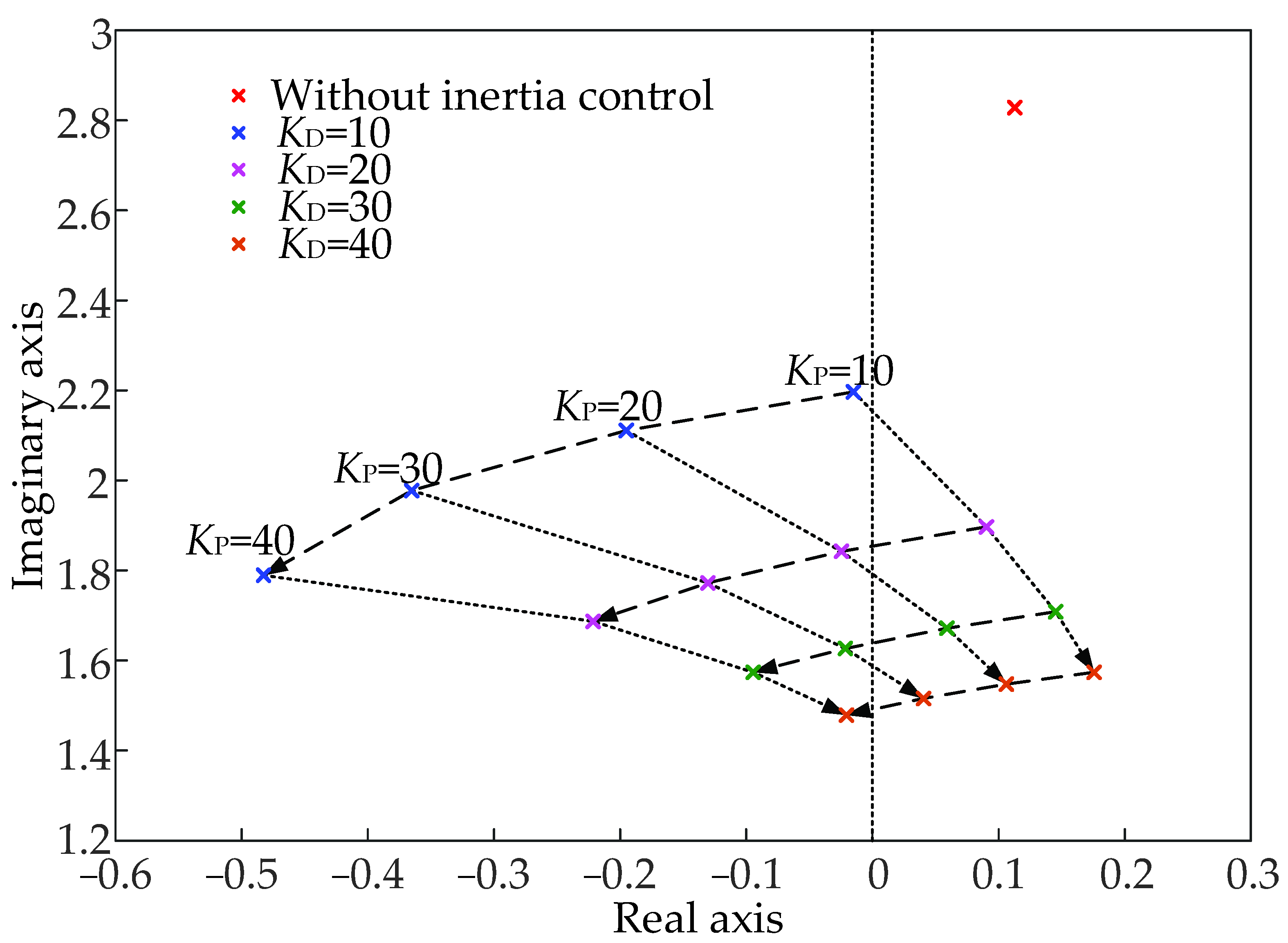
The influence of the gain KP and the gain KD in the IC on the LFO characteristics of the system is studied and analyzed. The influence of gains of different control links on the eigenvalue of the LFO mode is shown in Figure 3.
Figure 3 reveals that with the increase of the gain KD, the eigenvalue of the LFO mode will gradually move to the right in the complex plane, and the corresponding damping ratio will decrease. However, with the increase of the gain KP, the eigenvalue of the LFO mode will gradually move to the left in the complex plane, and the corresponding damping ratio will increase.
According to Figure 3, within the studied value range of the control parameters (KD = 10~40, KP = 10~40), when the gain KP is small, if the gain KD is also small, the integration of IC will make the eigenvalue of the LFO mode move to the left and the corresponding oscillation damping ratio increase. This evidence indicates that the integration of IC is beneficial to suppress the LFO of the system in this case. However, with a smaller value of the gain KP, if KD increases to a particular value, the integration of IC will make the eigenvalue of the LFO mode move to the right and the corresponding damping ratio decrease. In this case, the integration of IC is not conducive to suppress the LFO of the system. When the value of gain KP is large, although the increase of KD will have a negative effect on the suppression of LFO, the integration of IC is generally conducive to the suppression of LFO. The simulation results further show that whether the integration of IC is conducive to the suppression of LFO is related to the selection of control parameters, and the simulation results are consistent with the theoretical analysis results.
3.2. Four-Machine Two-Area System
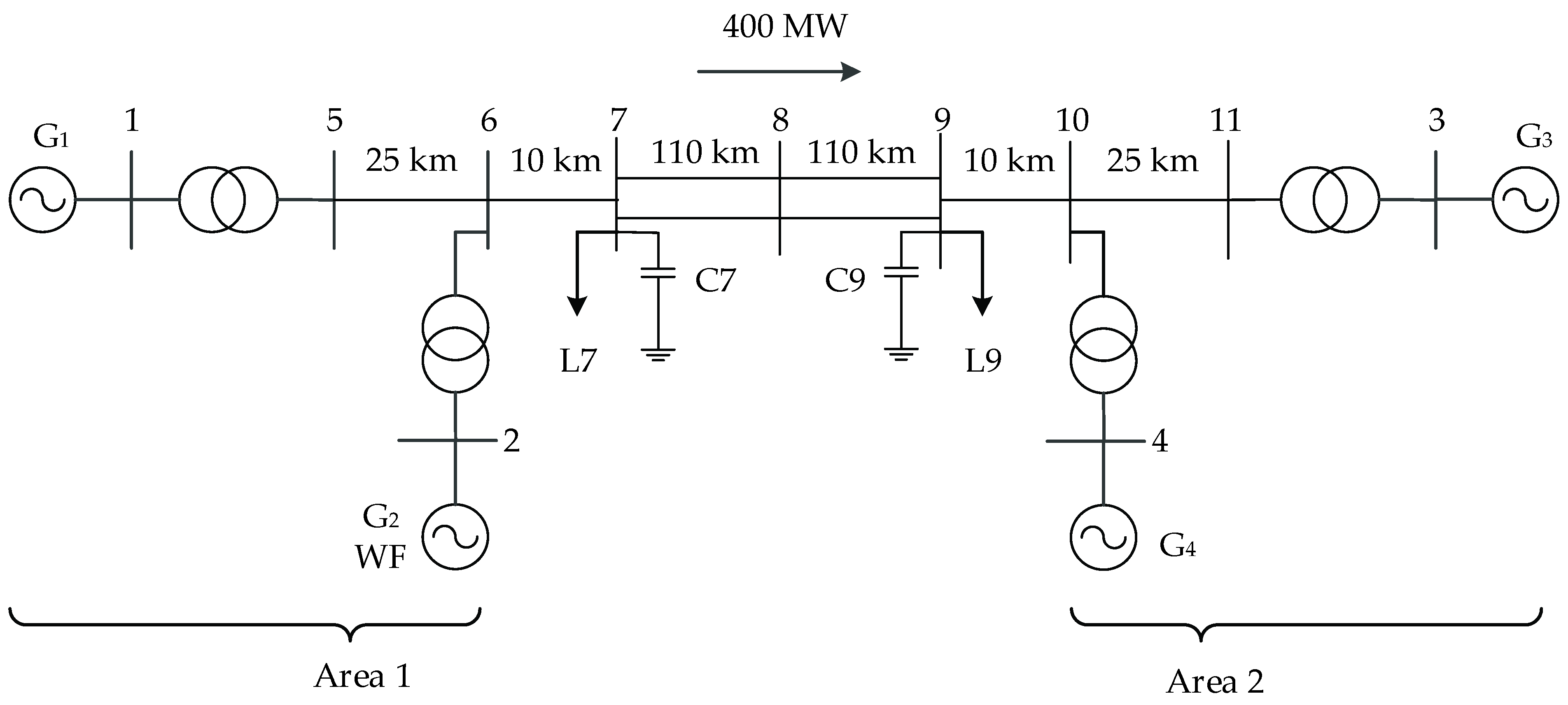
Further research is carried out based on the classical four-machine two-area system model [29], which is shown in Figure 4. Control parameters of generators are presented in Table 1 [29]. The synchronous generator G2 at node 6 is completely replaced by a DFIG-based WF. The active power output of the WF is 700 MW, and the parameters of WTs are the same as those in Section 3.1.
Firstly, the LFO modes of the system before and after the integration of the IC are compared and analyzed. In the simulation, in order to make the WT have good inertia support capability, KD = 40 and KP = 10 are selected. Regarding the setting up process of the control parameters, one can refer to [30,31,32,33]. The simulation results are shown in Table 2.
It can be seen from Table 2 that after the integration of IC of DFIG-based WTs, the eigenvalue of intra-area oscillation mode moves slightly to the left, and the damping ratio increases. The integration of IC is conducive to the suppression of intra-area oscillation mode. However, the integration of IC has a great negative impact on the inter-area oscillation mode. It is obvious that the eigenvalue of inter-area oscillation mode moves to the right and the damping ratio decreases after the integration of IC.
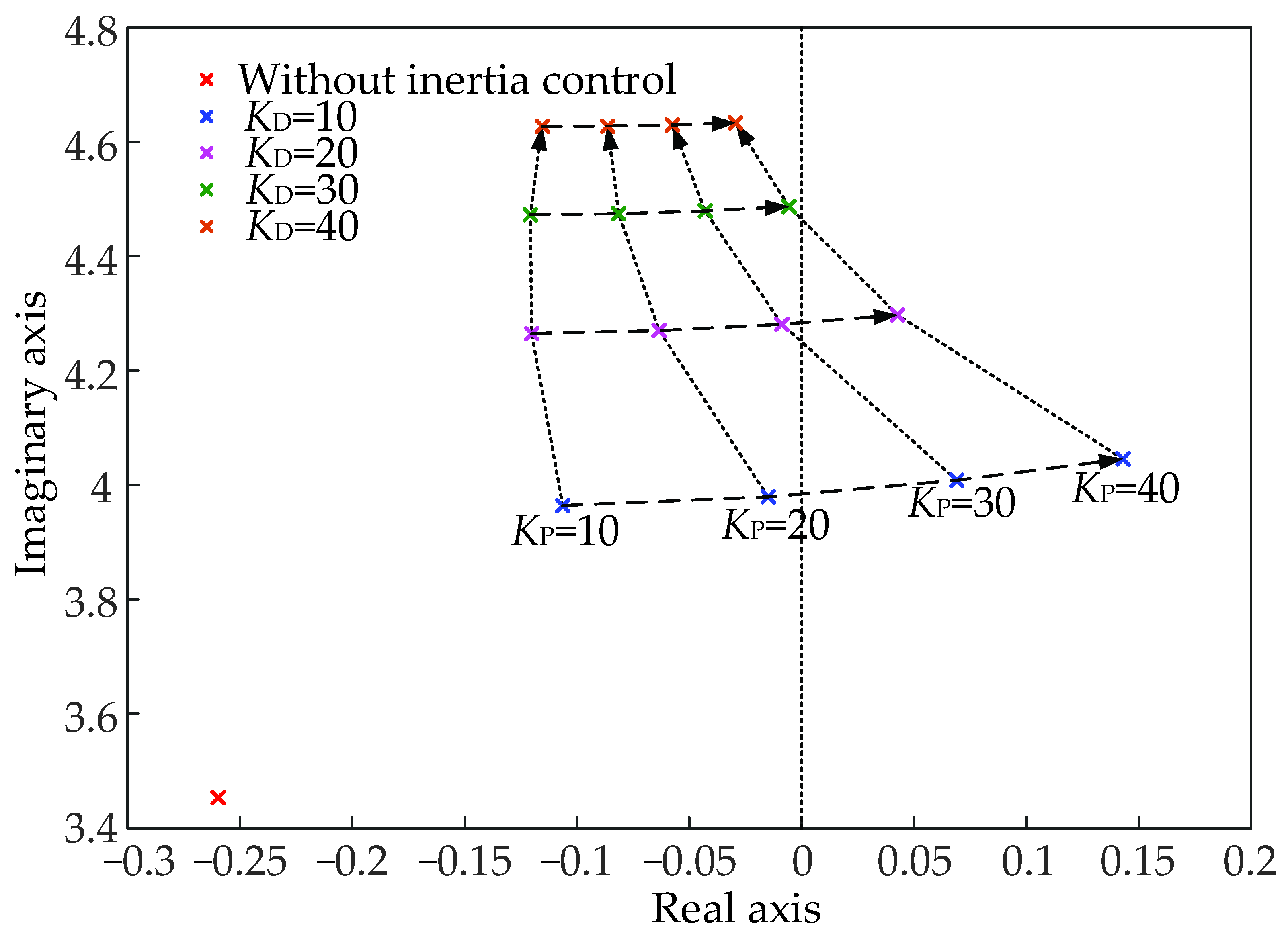
Therefore, the influence of the gain KP and KD in the IC strategy on the inter-area oscillation mode of the four-machine two-area system is mainly studied. The influence of gains of different control links on the eigenvalue of inter-area oscillation mode is shown in Figure 5.
According to Figure 5, when KP is small, with the increase of KD, the eigenvalue of the inter-area oscillation mode first moves left and then right, and the corresponding damping ratio first increases and then decreases; when KP is large, with the increase of KD, the eigenvalue of the inter-area oscillation mode continuously moves to the left, and the corresponding damping ratio also increases. Generally, the increase of the gain KD is beneficial to the suppression of the inter-area oscillation mode. However, with the increase of KP, the eigenvalue of the inter-area oscillation mode continuously moves to the right, and the corresponding damping ratio also decreases. Therefore, in the four-machine two-area system model, the integration of the frequency deviation control link in the IC has a negative impact on the inter-area oscillation suppression.
In addition, it can be found that within the studied value range of the control parameters (KD = 10~40, KP = 10~40), no matter what the values of gain KP and KD in the IC strategy are, the integration of IC makes the eigenvalue of the inter-area oscillation mode move to the right, and the corresponding damping ratio decrease. This evidence suggests that the IC is not conducive to the suppression of the oscillation mode.
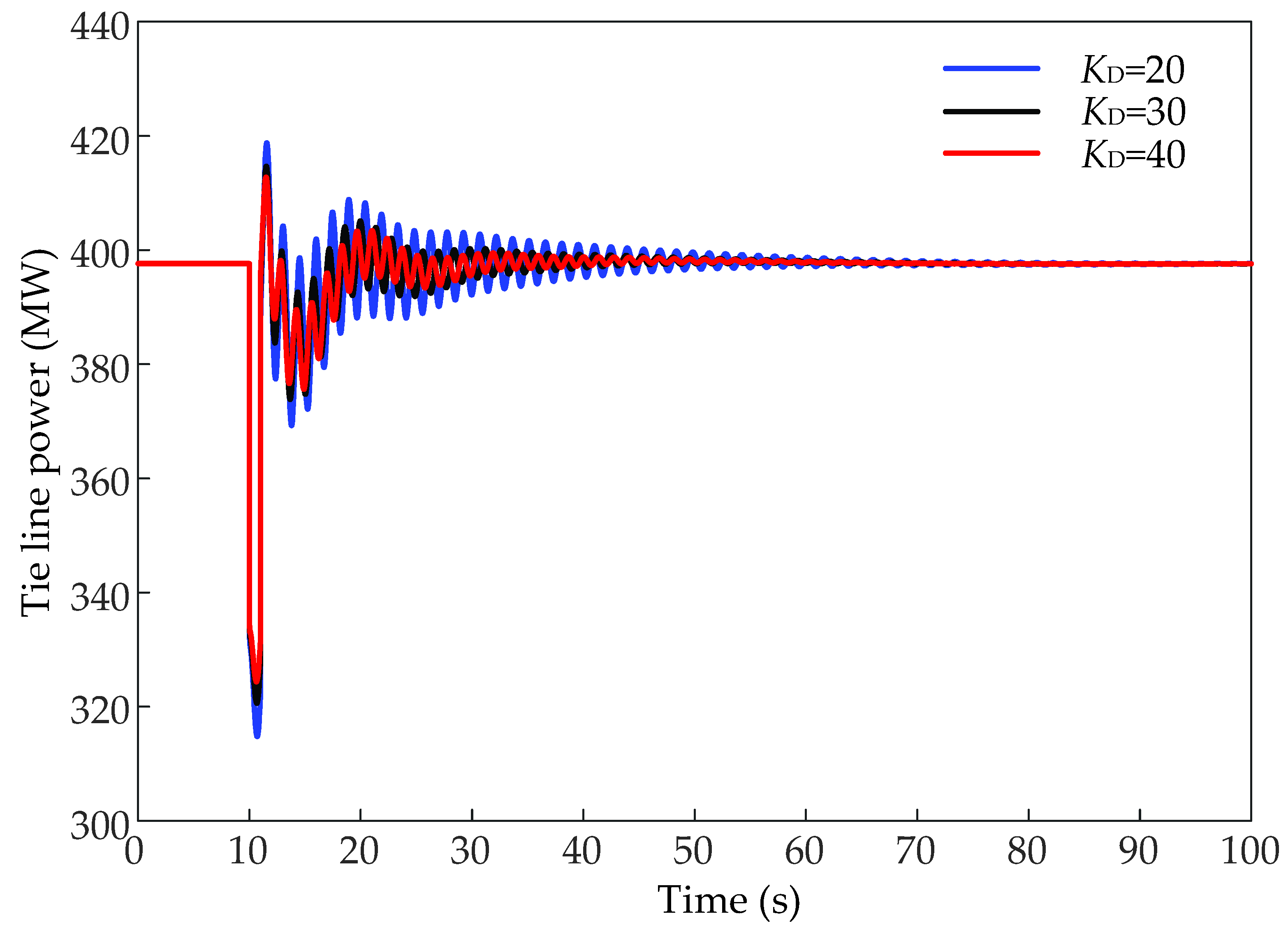
Furthermore, the time domain simulation is carried out based on the four-machine two-area system model described above. In the simulation, the active load at node 7 suddenly increases by 200 MW at 10 s and the suddenly increased load is removed after 1 s. The response curves of tie-line power with different control parameters are compared, and the simulation results are shown in Figure 6 and Figure 7.
It can be seen from Figure 6 that when KP = 20, the oscillation of tie-line power decreases with the increase of KD, which indicates that the increase of KD is conducive to inter-area oscillation suppression. It can be seen from Figure 7 that when KD = 40, with the increase of KP, the oscillation of tie-line power increases. It shows that the inter-area oscillation increases with the increase of KP. The time domain simulation results are consistent with the modal analysis results.
Comparing the influence of the IC on the LFO characteristics under the two-machine infinite-bus system model and the four-machine two-area system model established in this paper, it can be found that due to the change of system structure, the influence of the integration of the IC on the inter-area oscillation mode of the four-machine two-area system is quite different from that on the low frequency oscillation mode of the two-machine infinite-bus system. Within the studied value range of the control parameters, in the two-machine infinite-bus system model, the integration of the IC may have a positive effect or a negative effect on the low-frequency oscillation suppression when different control parameters are taken. The frequency differential control link and the frequency deviation control link positively and negatively impact suppressing low-frequency oscillations, respectively. However, in the four-machine two-area system model, the impact rules of the IC parameters on LFO in two-machine infinite-bus systems are not applicable. In the four-machine two-area system, no matter what the control parameters are, the integration of the IC always has adverse effects on the inter-area oscillation suppression.
4. Inertia Control Strategy of DFIG-Based Wind Turbine Considering Low-Frequency Oscillation Suppression
It can be seen from the above research that the integration of the IC may have negative effects on some LFO modes. Therefore, it is necessary to propose an improved IC strategy of DFIG-based WTs considering LFO suppression, which enhances the inertia support capability of DFIG-based WTs and suppresses the LFO simultaneously.
4.1. Improved Inertia Control Strategy of DFIG-Based Wind Turbine
The DFIG-based WT is not a specialized stability control device; thus, its rotor speed cannot be changed by adding the PSS to adjust the excitation as the synchronous generator. However, the DFIG-based WT can achieve damping control similar to the flexible AC transmission system (FACTS) and suppress power system oscillation by adjusting the power flow. The active power output of the DFIG-based WT can be adjusted by adding a control link related to the system oscillation signal in the power control link.
The control structure of the proposed improved IC strategy is shown in Figure 8. In reference to the damping control method of the DFIG-based WTs, a damping control link is added to the IC strategy of the DFIG-based WTs to suppress the LFO. The regulation of the active power output to achieve IC and the regulation of the active power output to achieve LFO suppression are added to the active power reference value given by the MPPT control. On this basis, the final active power reference value of the rotor-side converter control is generated.
In the proposed improved IC strategy, the control link of the IC is the same as that of the IC adopted in the previous section. In order to suppress the LFO, a damping control link is introduced. At present, the selections of the feedback signal for damping control of DFIG-based WTs are usually frequency, rotor speed difference between synchronous generators, output active power deviation of DFIG-based WTs, etc. [15,16,21,22,23,24]. In this paper, the control feedback signal is selected as the frequency deviation of the system without adding other signals. In the damping control link, the washout block is a high-pass filter, whose function is to block the steady-state input signals, so that the LFO suppression module does not work when the system is in steady-state operation [34]. The phase compensation block is composed of two lead/lag blocks to compensate for the phase lag between the input frequency deviation and the generator electrical torque [24,29]. K is the gain of the damping control link, and a saturation block is added after the gain K to ensure that the active power output after the control link is limited within the capacity of the inverter.
4.2. Simulation Analysis
The simulation analysis is based on the model described in Section 3.2. The time constant Tw of the high-pass filter should be high enough to allow signals associated with oscillations in the input signal to pass unchanged. Via numerical simulation [35], we set Tw = 10 s, and T1 = T3 = 1.5 s, T2 = T4 = 0.25 s. When the IC strategy is adopted, KD = 40 and KP = 10 are selected to make the WT have a good inertia support capability. Therefore, in the proposed improved IC strategy, KD = 40 and KP = 10 are also selected for further simulation analysis.
4.2.1. The Influence on the Inertia Support Capability
Firstly, the influence of the proposed IC strategy on the inertia support capability of the DFIG-based WT is studied. Additionally, the influence of the integration of the damping control link on the inertia support capacity is thoroughly examined. In the simulation, the active load at node 7 suddenly increases by 200 MW at 10 s, resulting in the change of system frequency. The frequency response curves of the system with different values of the damping control gain K are shown in Figure 9.
It can be seen from Figure 9 that the system frequency hardly changes with the change of the gain K. Therefore, it is found that the integration of the damping control link has little effect on the inertia support capability of DFIG-based WTs. When the improved IC strategy or the original IC strategy is adopted, the WT has the same inertia support capability.
4.2.2. The Influence on the Suppression of Low-Frequency Oscillation
The influence of the integration of the damping control link on the LFO characteristics of the system is studied by the modal analysis method. The modal analysis results with different values of the damping control gain K are shown in Table 3.
From Table 3, it can be seen that, compared with the original IC, the integration of the damping control link is unfavorable for the suppression of the intra-area oscillation, but is beneficial for the suppression of the inter-area oscillation. Moreover, with the increase of the gain K, the greater the negative effect of the damping control link on the intra-area oscillation suppression is, and the greater the beneficial effect of the damping control link on the inter-area oscillation suppression is. Compared with the MPPT control, the integration of the original IC is advantageous to the suppression of intra-area oscillation and disadvantageous to the suppression of inter-area oscillation. However, compared with the MPPT control, the integration of the proposed improved IC strategy is beneficial to the suppression of both the intra-area oscillation and the inter-area oscillation when an appropriate damping control gain K is selected. At the same time, it can be obtained that the change of gain K has less influence on the intra-area oscillation mode and greater influence on the inter-area oscillation mode. Therefore, in order to make the proposed improved IC strategy beneficial to the suppression of both the intra-area oscillation and the inter-area oscillation compared with the MPPT control, there is a large value range for the gain K.
The time-domain simulation is also carried out. In the simulation, the active load at node 7 suddenly increases by 200 MW at 10 s, and the suddenly increased load is removed after 1 s. The response curves of tie-line power with different values of the damping control gain K are compared, and the simulation results are shown in Figure 10.
It can be seen from Figure 10 that, with the increase of damping control gain K, the tie-line power oscillation decreases. It is shown that the integration of the damping control link is conducive to the suppression of the inter-area LFO, and the time domain simulation results are consistent with the modal analysis results.
5. Conclusions
The integration of the IC of DFIG-based WTs may affect the LFO characteristics of power systems. This paper focuses on exploring and comparing the impact rules of the IC of DFIG-based WTs on the LFO in systems with different structures. The analysis and simulation are based on the two-machine infinite-bus system model and the four-machine two-area system model. It is shown that the impact rules of the IC of DFIG-based WTs on LFO characteristics are closely related to the selection of IC parameters and the system structures. In the two-machine infinite-bus system, the IC may have a positive or a negative effect on the low-frequency oscillation suppression, depending on values of control parameters. The frequency differential control link and the frequency deviation control link positively and negatively impact suppressing low-frequency oscillations, respectively. While in the four-machine two-area system, such impacts are not observed. In the four-machine two-area system, the IC always exerts adverse effects on the inter-area oscillation suppression. On this basis, considering that IC might worsen the LFO in some systems, an improved IC strategy of DFIG-based WTs is proposed where a damping control link is added in the IC strategy of the DFIG-based WT. By selecting the appropriate control parameters, the improved IC strategy can not only make the DFIG-based WTs have the inertia support capability, but also suppress both the intra-area and inter-area LFO of the system.
In addition, the setting of control parameters in the damping control link in the improved IC is also related to the system structure. In the follow-up work, approaches to optimize control parameters, e.g., the artificial intelligence algorithm, could be investigated to better suppress the LFO.
Author Contributions
Conceptualization, H.L.; methodology, H.L. and X.Y.; software, S.Y.; validation, H.L., S.Y. and X.Y.; formal analysis, H.L. and S.Y.; data curation, S.Y.; writing—original draft preparation, H.L. and S.Y.; writing—review and editing, H.L.; visualization, S.Y. and X.Y.; supervision, H.L. All authors have read and agreed to the published version of the manuscript.
Funding
This research received no external funding.
Conflicts of Interest
The authors declare no conflict of interest.
References
- Hydro-Québec TransÉnergie. Technical Requirements for the Connection of Generating Stations to the Hydro-Québec Transmission System. Available online: https://www.hydroquebec.com/transenergie/en/connecting-to-hydroquebec-system.html (accessed on 18 July 2021).
- National Grid Electricity System Operator. The Grid Code. Available online: https://www.nationalgrideso.com/industry-information/codes/grid-code/code-documents (accessed on 18 July 2021).
- The European Commission. The Network Code on Requirements for Generators. Available online: https://www.entsoe.eu/network_codes/rfg/ (accessed on 18 July 2021).
- Yan, X.; Sun, X. Inertia and droop frequency control strategy of doubly-fed induction generator based on rotor kinetic energy and supercapacitor. Energies 2020, 13, 3697. [Google Scholar] [CrossRef]
- Li, C.; Hang, Z.; Zhang, H.; Guo, Q.; Zhu, Y.; Terzija, V. Evaluation of DFIGs’ primary frequency regulation capability for power systems with high penetration of wind power. Energies 2020, 13, 6178. [Google Scholar] [CrossRef]
- Abouzeid, S.I.; Guo, Y.F.; Zhang, H.C. A frequency response strategy for variable speed wind turbine based on a dynamic inertial response and tip-speed ratio control. Electr. Eng. 2019, 101, 35–44. [Google Scholar] [CrossRef]
- Shao, H.; Cai, X.; Zhou, D.; Li, Z.; Zheng, D.; Cao, Y.; Wang, Y.; Rao, F. Equivalent modeling and comprehensive evaluation of inertia emulation control strategy for DFIG wind turbine generator. IEEE Access 2019, 7, 64798–64811. [Google Scholar] [CrossRef]
- Beltran, H.; Harrison, S.; Egea-Àlvarez, A.; Xu, L. Techno-economic assessment of energy storage technologies for inertia response and frequency support from wind farms. Energies 2020, 13, 3421. [Google Scholar] [CrossRef]
- Liu, J.L.; Yang, Z.F.; Yu, J.; Huang, J.K.; Li, W.Y. Coordinated control parameter setting of DFIG wind farms with virtual inertia control. Int. J. Electr. Power. Energy. Syst. 2020, 122, 106167. [Google Scholar] [CrossRef]
- Sun, L.; Liu, K.; Hu, J.; Hou, Y. Analysis and mitigation of electromechanical oscillations for DFIG wind turbines involved in fast frequency response. IEEE Trans. Power Syst. 2019, 34, 4547–4556. [Google Scholar] [CrossRef]
- Ma, J.; Zhao, D.; Shen, Y.; Phadke, A.G. Research on positioning method of low frequency oscillating source in DFIG-integrated system with virtual inertia control. IEEE Trans. Sustain. Energy 2020, 11, 1693–1706. [Google Scholar] [CrossRef]
- Wu, G.; Sun, H.; Zhao, B.; Xu, S.; Zhang, X.; Egea-Àlvarez, A.; Wang, S.; Li, G.; Li, Y.; Zhou, X. Low-frequency converter-driven oscillations in weak grids: Explanation and damping improvement. IEEE Trans. Power Syst. 2021, 36, 5944–5947. [Google Scholar] [CrossRef]
- Silva-Monroy, C.; Neely, J.; Byrne, R.; Elliott, R.; Schoenwald, D. Wind generation controls for damping of inter-area oscillations. In Proceedings of the 2013 IEEE Power & Energy Society General Meeting, Vancouver, BC, Canada, 21–25 July 2013. [Google Scholar]
- Pulgar-Painemal, H.; Gálvez-Cubillos, R. Wind farms participation in frequency regulation and its impact on power system damping. In Proceedings of the 2013 IEEE Grenoble Conference, Grenoble, France, 16–20 June 2013. [Google Scholar]
- Geng, H.; Xi, X.; Liu, L.; Yang, G.; Ma, J. Hybrid modulated active damping control for DFIG-based wind farm participating in frequency response. IEEE Trans. Energy Convers. 2017, 32, 1220–1230. [Google Scholar] [CrossRef]
- Xi, X.Z.; Geng, H.; Yang, G. Small signal stability of weak power system integrated with inertia tuned large scale wind farm. In Proceedings of the 2014 IEEE Innovative Smart Grid Technologies—Asia, Kuala Lumpur, Malaysia, 20–23 May 2014. [Google Scholar]
- Lucas, E.; Campos-Gaona, D.; Anaya-Lara, O. Assessing the Impact of DFIG Synthetic Inertia Provision on Power System Small-Signal Stability. Energies 2019, 12, 3440. [Google Scholar] [CrossRef] [Green Version]
- Ying, J.; Yuan, X.; Hu, J.; He, W. Impact of inertia control of DFIG-based WT on electromechanical oscillation damping of SG. IEEE Trans. Power Syst. 2018, 33, 3450–3459. [Google Scholar] [CrossRef]
- Ma, J.; Qiu, Y.; Li, Y.; Zhang, W.; Song, Z.; Thorp, J.S. Research on the impact of DFIG virtual inertia control on power system small-signal stability considering the phase-locked loop. IEEE Trans. Power Syst. 2017, 32, 2094–2105. [Google Scholar] [CrossRef]
- Geng, H.; Xi, X.Z.; Yang, G. Small-signal stability of power system integrated with ancillary-controlled largescale DFIG-based wind farm. IET Renew. Power Gener. 2017, 11, 1191–1198. [Google Scholar] [CrossRef]
- Hughes, F.M.; Anaya-Lara, O.; Jenkins, N.; Strbac, G. A power system stabilizer for DFIG-based wind generation. IEEE Trans. Power Syst. 2006, 21, 763–772. [Google Scholar] [CrossRef]
- Dominguez-Garcia, J.L.; Gomis-Bellmunt, O.; Bianchi, F.D.; Sumper, A. Power oscillation damping supported by wind power: A review. Renewable Sustain. Energy Rev. 2012, 16, 4994–5006. [Google Scholar] [CrossRef]
- Surinkaew, T.; Ngamroo, I. Hierarchical co-ordinated wide area and local controls of DFIG wind turbine and PSS for robust power sscillation damping. IEEE Trans. Sustain. Energy 2016, 7, 943–955. [Google Scholar] [CrossRef]
- Morshed, M.J.; Fekih, A. A probabilistic robust coordinated approach to stabilize power oscillations in DFIG-based power systems. IEEE Trans. Ind. Inf. 2019, 15, 5599–5612. [Google Scholar] [CrossRef]
- Singh, M.; Allen, A.J.; Muljadi, E.; Gevorgian, V.; Zhang, Y.; Santoso, S. Interarea oscillation damping controls for wind power plants. IEEE Trans. Sustain. Energy 2015, 6, 967–975. [Google Scholar] [CrossRef]
- Ramirez-Gonzalez, M.; Malik, O.; Castellanos-Bustamante, R.; Calderon-Guizar, G. Conventional and fuzzy PODCs for DFIG-based wind farms and their impact on inter-area and torsional oscillation damping. IET Renew. Power Gener. 2017, 11, 333–340. [Google Scholar] [CrossRef]
- Xi, X.Z.; Geng, H.; Yang, G.; Li, S.; Gao, F. Two-level damping control for DFIG-based wind farm providing synthetic inertial service. IEEE Trans. Ind. Appl. 2018, 54, 1712–1723. [Google Scholar] [CrossRef]
- Yu, S.S.; Chau, T.K.; Fernando, T.; Iu, H.H. An enhanced adaptive phasor power oscillation damping approach with latency compensation for modern power systems. IEEE Trans. Power Syst. 2018, 33, 4285–4296. [Google Scholar] [CrossRef]
- Kundur, P. Power System Stability and Control; McGraw-Hill: New York, NY, USA, 1994; Chapter 12. [Google Scholar]
- Kayikci, M.; Milanovic, J.V. Dynamic contribution of DFIG-based wind plants to system frequency disturbances. IEEE Trans. Power Syst. 2009, 24, 859–867. [Google Scholar] [CrossRef]
- Mauricio, J.M.A.; Gomez-Exposito, M.A.; Martinez Ramos, J.L. Frequency regulation contribution through variable-speed wind energy conversion systems. IEEE Trans. Power Syst. 2009, 24, 173–180. [Google Scholar] [CrossRef]
- Nguyen, H.T.; Yang, G.; Nielsen, A.H.; Jensen, P.H. Frequency Stability Enhancement for Low Inertia Systems Using Synthetic Inertia of Wind Power. In Proceedings of the 2017 IEEE Power & Energy Society General Meeting, Chicago, IL, USA, 16–20 July 2017. [Google Scholar]
- Nguyen, H.T.; Yang, G.; Nielsen, A.H.; Jensen, P.H. Combination of synchronous condenser and synthetic inertia for frequency stability enhancement in low-inertia systems. IEEE Trans. Sustain. Energy 2019, 10, 997–1005. [Google Scholar] [CrossRef] [Green Version]
- Surinkaew, T.; Ngamroo, I. Coordinated robust control of DFIG wind turbine and PSS for stabilization of power oscillations considering system uncertainties. IEEE Trans. Sustain. Energy 2014, 5, 823–833. [Google Scholar] [CrossRef]
- Hao, Z.; Yu, Y.; Zeng, Y. A control strategy for increasing power system damping with wind turbine-driven doubly-fed induction generator. Autom. Electr. Power Syst. 2011, 35, 25–29. [Google Scholar]
Figure 1.
Active power control strategy of DFIG-based WTs under IC.

Figure 2.
Schematic diagram of the two-machine infinite-bus system.

Figure 3.
Eigenvalue analysis results of the LFO mode under different control gains.

Figure 4.
Schematic diagram of four-machine two-area system.

Figure 5.
Eigenvalue analysis results of the inter-area oscillation mode under different control gains.
Figure 5.
Eigenvalue analysis results of the inter-area oscillation mode under different control gains.

Figure 6.
The response curves of tie-line power with different values of the gain KD (KP = 20).

Figure 7.
The response curves of tie-line power with different values of the gain KP (KD = 40).

Figure 8.
IC strategy of DFIG-based WT considering low frequency oscillation suppression.

Figure 9.
The frequency response curves of the system with different values of the damping control gain K (KD = 40, KP = 10).
Figure 9.
The frequency response curves of the system with different values of the damping control gain K (KD = 40, KP = 10).

Figure 10.
The response curves of tie-line power with different values of the damping control gain K (KD = 40, KP = 10).
Figure 10.
The response curves of tie-line power with different values of the damping control gain K (KD = 40, KP = 10).


Table 1.
Control parameters of generators in the four-machine two-area system.
| Parameters | Values | Parameters | Values |
|---|---|---|---|
| 1.8 p.u. | 0.2 p.u. | ||
| 0.3 p.u. | 0.0025 p.u. | ||
| 0.25 p.u. | 8.0 s | ||
| 1.7 p.u. | 0.03 s | ||
| 0.55 p.u. | 0.4 s | ||
| 0.25 p.u. | 0.05 s | ||
| (in G1) | 6.5 s | (in G3 and G4) | 6.175 s |
Table 2.
The LFO modes of the system before and after the integration of the IC.
| Case | Mode #no. | Eigenvalue | Damping Ratio | Related Generators |
|---|---|---|---|---|
| Without IC | Intra-area #1 | −0.3582 ± j 6.6884 | 0.0535 | G3, G4 |
| Inter-area #2 | −0.2597 ± j 3.4535 | 0.0750 | G1, G3, G4 | |
| With IC | Intra-area #1 | −0.3739 ± j 6.6243 | 0.0564 | G3, G4 |
| Inter-area #2 | −0.1155 ± j 4.6272 | 0.0245 | G1, G3, G4, WF |
Table 3.
The LFO modes of the system with different values of the damping control gain K (KD = 40, KP = 10).
Table 3.
The LFO modes of the system with different values of the damping control gain K (KD = 40, KP = 10).
| Case | Mode #no. | Eigenvalue | Damping Ratio | Related Generators |
|---|---|---|---|---|
| MPPT control | Intra-area #1 | −0.3582 ± j 6.6884 | 0.0535 | G3, G4 |
| Inter-area #2 | −0.2597 ± j 3.4535 | 0.0750 | G1, G3, G4 | |
| K = 0 (original IC) | Intra-area #1 | −0.3739 ± j 6.6243 | 0.0564 | G3, G4 |
| Inter-area #2 | −0.1155 ± j 4.6272 | 0.0245 | G1, G3, G4, WF | |
| K = 50 | Intra-area #1 | −0.3660 ± j 6.6087 | 0.0553 | G3, G4 |
| Inter-area #2 | −0.2374 ± j 4.7039 | 0.0504 | G1, G3, G4, WF | |
| K = 100 | Intra-area #1 | −0.3610 ± j 6.5924 | 0.0547 | G3, G4 |
| Inter-area #2 | −0.3333 ± j 4.8050 | 0.0692 | G1, G3, G4, WF | |
| K = 150 | Intra-area #1 | −0.3588 ± j 6.5762 | 0.0545 | G3, G4 |
| Inter-area #2 | −0.3963 ± j 4.9182 | 0.0803 | G1, G3, G4, WF |
Publisher’s Note: MDPI stays neutral with regard to jurisdictional claims in published maps and institutional affiliations. |
© 2021 by the authors. Licensee MDPI, Basel, Switzerland. This article is an open access article distributed under the terms and conditions of the Creative Commons Attribution (CC BY) license (https://creativecommons.org/licenses/by/4.0/).
Share and Cite
MDPI and ACS Style
Liu, H.; Yang, S.; Yuan, X. Inertia Control Strategy of DFIG-Based Wind Turbines Considering Low-Frequency Oscillation Suppression. Energies 2022, 15, 29. https://0-doi-org.brum.beds.ac.uk/10.3390/en15010029
AMA Style
Liu H, Yang S, Yuan X. Inertia Control Strategy of DFIG-Based Wind Turbines Considering Low-Frequency Oscillation Suppression. Energies. 2022; 15(1):29. https://0-doi-org.brum.beds.ac.uk/10.3390/en15010029
Chicago/Turabian StyleLiu, Haoming, Suxiang Yang, and Xiaoling Yuan. 2022. "Inertia Control Strategy of DFIG-Based Wind Turbines Considering Low-Frequency Oscillation Suppression" Energies 15, no. 1: 29. https://0-doi-org.brum.beds.ac.uk/10.3390/en15010029
Note that from the first issue of 2016, this journal uses article numbers instead of page numbers. See further details here.