1. Introduction
Roof bolting is the most popular type of support in drifts, crosscuts and other workings in underground mines. Its popularity is ensured by its low price, ease of assembly and transport, the wide range of bolts and whole bolting systems being available on the market and the ability to adjust them to various geological and mining conditions [
1,
2,
3,
4,
5,
6,
7,
8]. Although roof bolting is very popular, it cannot be applied in every scenario. Various circumstances, equally economical, technical and historical, made Polish coal mines use roof bolting only as a supplementary support, additional to typical steel yielding arches. Independent rock bolt support is rarely used in Polish coal mines, despite its popularity in metal ore mines or for underground structures, such as tunnels [
8,
9,
10,
11,
12,
13,
14].
In 2019, JSW (Jastrzębska Spółka Węglowa) started a project for the introduction of independent rock bolting support in Polish coal mines. The aim of the project is to determine the possibility of use of such a type of support in mine workings to help reduce the costs of development works, maintain a high level of safety, as application of roof bolting is a common way of optimizing development costs in underground mines [
15]. In fact, attempts to introduce independent roof bolting in Polish coal mines were made in history, but they all failed due to different reasons. Thus, the described project is the first modern attempt and, in contrast to historical projects, it was thoroughly analyzed and designed.
Properly planned and conducted monitoring is a key for maintaining stability and safety of the underground system. In the case of the project to introduce the independent rock bolting support in JSW mines, this aspect is particularly important because it is necessary to determine if roof bolting is capable to provide the proper level of safety. Monitoring of different mine objects and their parameters becomes an increasingly important branch of the mining industry. Over the years, numerous monitoring devices and systems were introduced in underground mines [
16,
17,
18,
19].
One of the most popular and simple means of monitoring, used for a long time in mine working, is measurement of delamination. Indicative and qualitative sensors are used. Such sensors are installed in the face of the working, because delamination is mostly formed immediately after rocks in the face have been cut. The main advantages of the delamination indicators are simple construction, easy assembly and read-out without the need to use specialized equipment. Data obtained is general, but usually sufficient. However, complex evaluation of the state and quality of the roof should be based on its qualitative assessment. Such measurements are conducted using different type if extensometers. Such a solution is more complicated, but the high accuracy of the measurement makes it the most popular in the world [
20,
21,
22].
Numerous producers offer different systems of automatic delamination measurement. Among them Geokon, ACE, Sissgeo (Multipoint Borehole Extensometer-MPBX: SISGEO, Milan, Italy). However, such systems cannot be applied in Polish coal mines, because of the lack of approval for use in underground mines in Poland (lack of Polish attestation) and its limited operating range, which can be problematic in case of significant roof deformations in workings influenced by mining pressure [
10,
20,
23,
24,
25].
Endoscope cameras have been used in mining industry for a number of years. The application of such devices allows one to obtain accurate output, but the measurement itself is time-consuming. Endoscopes allows one to precisely examine the character of delaminations and the area of the fracture zone [
20,
21,
26,
27,
28,
29]. Support and rock mass monitoring can also include a stress-strain measurement, which is conducted using various types of sensors. Such devices are usually used in tunnels to measure compressive stress in concrete. They are rarely used in the mining industry [
3,
20,
23,
26,
30,
31,
32,
33,
34].
The simplest method of rock mass and mine working monitoring is convergence measurement. For the purpose of the measurement, benchmarks are installed in the workings’ roof, floor and sidewalls. Measurements of the distance between benchmarks are conducted in time intervals. Vertical and horizontal distance can be measured, as well as perimeter of the working. Nowadays, convergence is often measured using laser scanners [
18,
35,
36,
37]. Telescopic scales can be also used for constant measurement of the convergence. However, due to practical issues, they can be applied only in workings, where movement of people and machinery is limited [
26,
35,
36,
37].
It should be emphasized that only simultaneous use of different methods of rock mass and mine working support monitoring provides fully complete and reliable data, because it allows one to compare results obtained using different tools and devices [
20,
26,
38]. Such an approach was applied in the Bw-1n roadway in Budryk Colliery, which was selected as a test working for the project of introduction of the independent rock bolting support in JSW coal mines. The exact method and procedure of the monitoring of the Bw-1n roadway are presented in following sections.
2. Method of the Rock Mass and Mine Support Monitoring in the Bw-1n Roadway in Budryk Colliery
The base of the bolting support control and monitoring is a visual control of bolts, accessories and equipment, conducted by miners responsible for bolts’ installation. Their duties are, among other things, visual control of the roadway, maintaining proper dimensions of the working, installation of the bolts in proper spacing and in compliance with bolting instruction, as well as drilling boreholes according to their specification, including proper diameter, length and inclination.
The key elements of the roadway support inspection are control of the grout quality, correctness of the bolt and pad installation, proper bolts’ spacing and testing of bolts’ load bearing capacity using tension jack.
Roadway stability control comprising use of different monitoring tools and devices is conducted by mine supervisors. It consists of everyday and periodic control. Everyday control, according to guidance of GIG (Main Mining Institute of Poland–Główny Instytut Górnictwa) consists of two-level extensometers observation. Two risk levels are marked on the indicators: safe and dangerous. There are two basic types of extensometers:
Bottom level extensometers–installed about 0.3 m deeper than the length of anchors used, near the axis of the roadway, spaced at intervals not less than 30 m. The maximum value of a delamination allowed is 50 mm. The safety level is fixed for a delamination greater than 2% of anchor length.
Top level extensometers–installed about 0.3 m deeper than doubled anchor length on the depth not smaller than 4.5 m, near the axis of the roadway, spaced at intervals not less than 30 m. The maximum value of a delamination allowed is 50 mm. The safety level is fixed for a delamination greater than 1.5% of the roadway width.
Moreover, an appraiser of the bolting should be notified if values of delamination exceed 50% of maximum values with significant growth dynamics. The presented maximum values were defined for a case of a roadway located in intact rock mass with no additional loads and other factors affecting its stability. The first periodic control station was designed at a maximum distance of 5 m from the beginning of the roadway supported with independent bolting. Locations of other stations were designed as dependent on geological and mining conditions.
Five periodic control stations were installed in the Bw-1n roadway. Measuring devices installed differ between the stations, however, all of them are equipped with:
instrumented bolts of varying amount and spacing,
extensometers of different construction and varying amount.
The first station also consists of extensometric probe installed in the axis of the roadway. Distances between subsequent stations varies. The first and second stations are located closer to each other than another stations. A cross section and top view of the second station, serving as an example, are presented in
Figure 1 and
Figure 2.
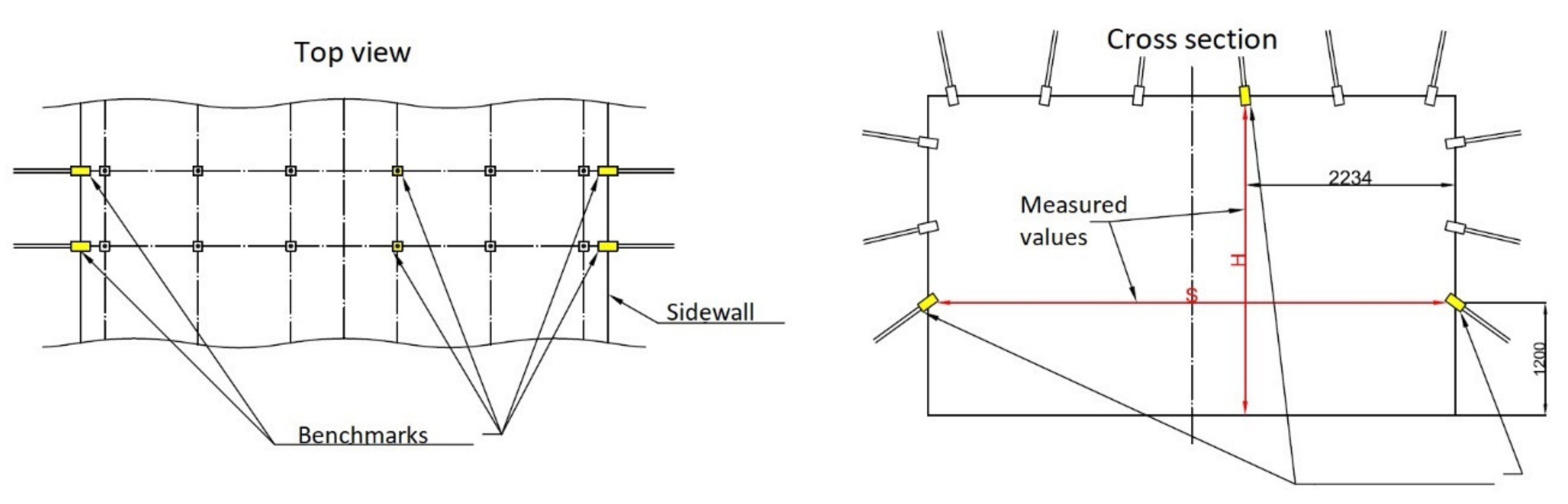
Measurement of the convergence is conducted using convergence control stations. Each station comprises two sets of benchmarks allowing to measure convergence in both vertical and horizontal directions. Similarly to the periodic control stations, five convergence control stations were installed in different spacing. Locations of convergence control stations are not identical to locations of periodic control stations. A cross section and top view of the convergence control station are presented in
Figure 3.
Designed frequency of conducting measurements of extensometers was:
visual control and record for three extensometers closest to the roadway face–once every working shift and once a day on days off;
visual control and record for other extensometers–once every week;
only visual control of other extensometers–once every working shift and once a day on days off;
visual control and record after the roadway driving is over–once every week.
Designed frequency of conducting measurements on periodic control stations and convergence control stations was:
during first two weeks of control station’s existence:
visual control and record on periodic control stations—once a day;
visual control and record on convergence control stations—once a week;
after two weeks:
visual control and record on both periodic and convergence control stations–once a month.
During the realization phase of the project, frequency of measurements was reduced.
3. Results
3.1. Roof Delamination Control–Extensometers
Figure 4,
Figure 5,
Figure 6,
Figure 7 and
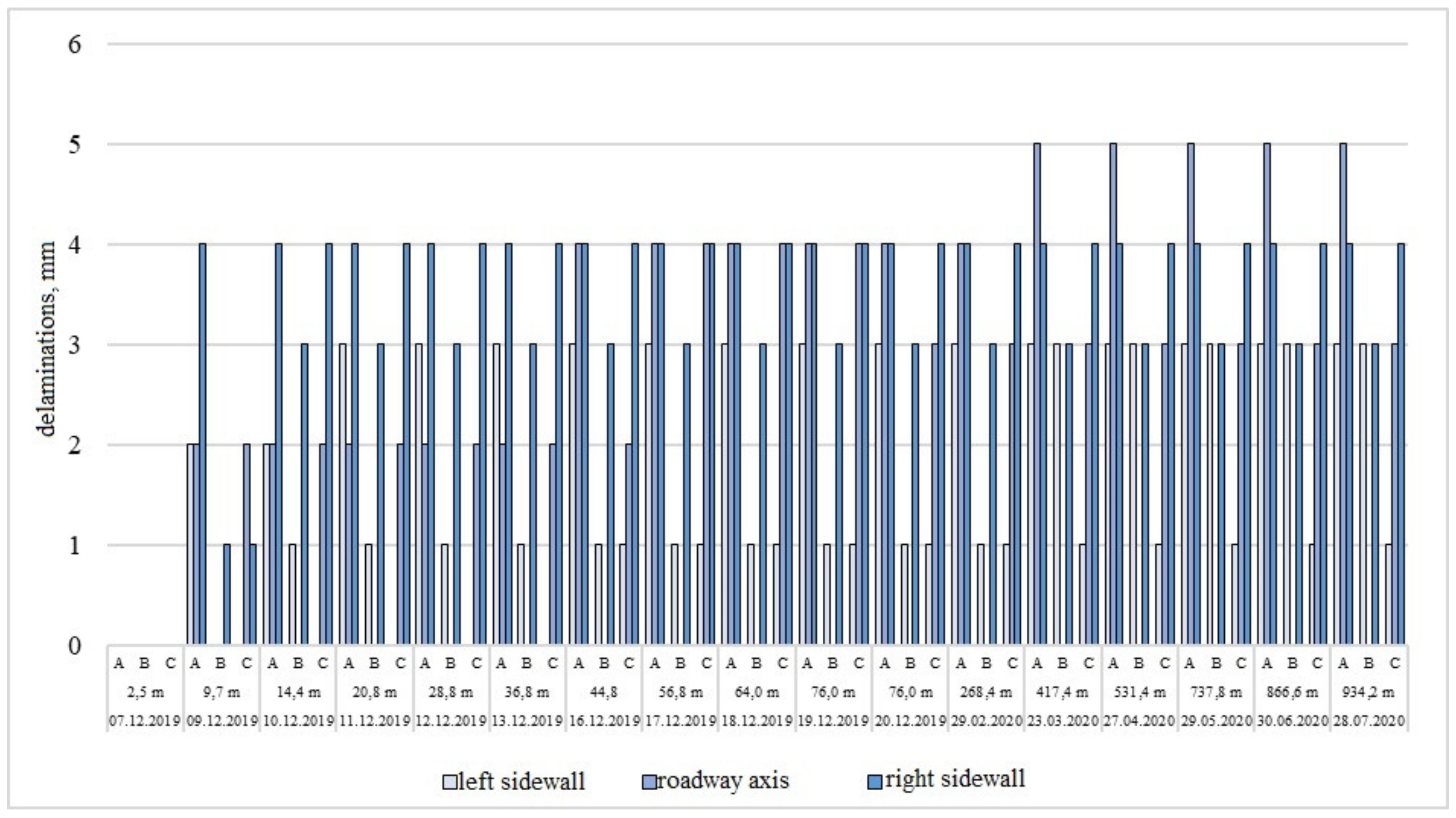
Figure 8 present values of roof delaminations measured on subsequent periodic control stations together with the date of measurement, distance between the station and the roadway face and depth (level) of the delamination. The greatest values of the delaminations were observed shortly after the extensometers were installed, which is related to small distance between the station and the roadway face. Stabilization of the delaminations’ values can be observed as the distance between the station and the roadway face growths. It is especially visible in diagrams presenting data from stations 1–4. It indicates a proper installation of roof bolting, which connects rock layers and prevents delaminations’ propagation.
On the first periodic control statins (
Figure 4) at the distance of about 25 m from the roadway face, increase of delaminations’ values at both sidewalls occurred. However, these values did not exceed critical values, thus there was no need to take preventive actions. Values of the delaminations in the roadway axis remained unchanged during the whole period of measurements.
Maximum delamination value measured on the second station (
Figure 5) was only 5 mm, which proves the effectiveness of the roof bolting and indicates that bolting spacing was designed correctly. On the third control station, the values of delaminations were measured only at the sides of the roadway (
Figure 6). Similarly to the second station, maximum values did not exceed 5 mm.
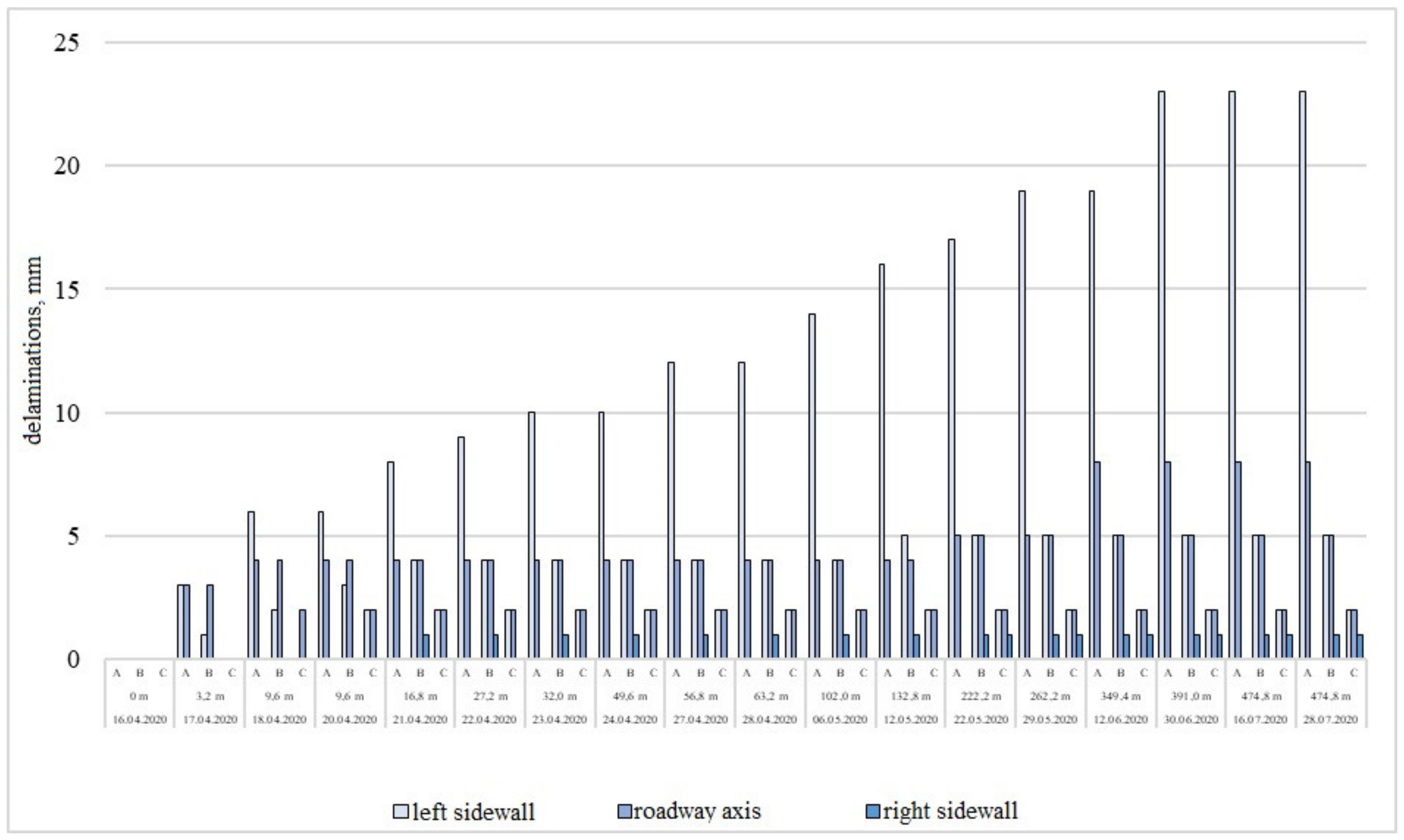
Constant growth of the delaminations’ value at the left side of the roadway was observed at the station no. 4 (
Figure 7). It stabilized at the value of 23 mm in the distance of 400 m from the roadway face. Due to significantly greater values of delaminations on the left side of the working, the decision was made to install additional anchor at that side.
Maximum values of the delaminations measured on the fifth periodic control station were equal 15 mm. Similarly to the station no. 4, they occurred on the left side of the roadway. Moreover, constant growth of delaminations’ value in the roadway axis was observed. It was probably caused by small distance between the station and the roadway face as well as with occurrence of unfavourable geological and mining conditions.
Figure 9 presents values of delaminations measured during everyday control. During the sixth month of the project (March 2020) exceedance of the allowed value was observed, indicating occurrence of fractures in the roof. Due to this situation, an on-site verification was conducted by the appraiser on 25 March 2020. Basing on the roof examination with a borescope, it was stated that the fractures were caused by the occurrence of thin coal layers. It was decided to install additional anchors in this area, also the bolt spacing for forthcoming phases of the project was changed. Provisions taken were successful, as no fractures in the roadway roof were noticed in subsequent project phases. Currently, the Bw-1n roadway is stable and values of delaminations remains at a safe level.
3.2. Roof Delamination–Multilevel Mechanical Extensometers and Extensometric Probes
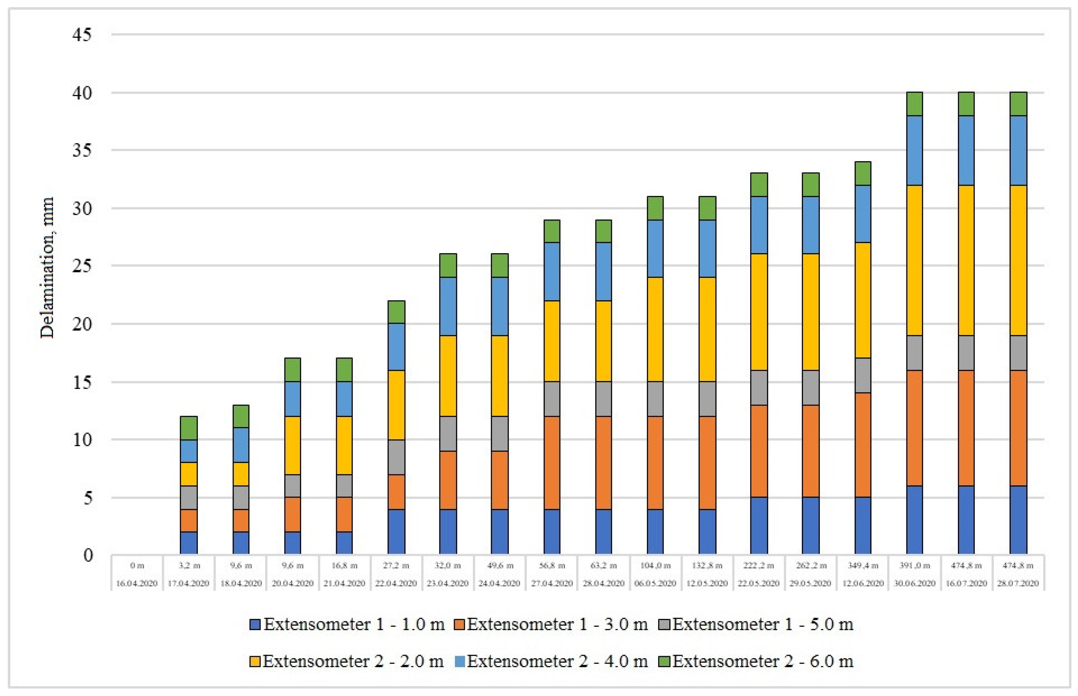
Range of the roof delaminations was monitored using extensomteric probe on the first periodic control station and multilevel mechanical extensometer on other stations. Values of the measured range remain unchanged. Values of both displacements and delaminations measured using an extensometric probe differs slightly (
Figure 10 and
Figure 11), but, due to the high sensitivity and accuracy of the probe, such differences might be omitted. Similarly, values obtained using multilevel mechanical extensometer (
Appendix A) remain stable in time. It is worth noting that it also applies to the fifth control station, which is located close to the roadway face.
3.3. Bolt Loading–Instrumented Bolts
Bolt loading was measured using instrumented bolts, equipped with strain gauges. Axial force variations between positive and negative values indicate existence of a fracture or delamination. Lateral moves of rock layers can lead bolt shearing, which in turn effects in high amplitudes of measured forces.
Load stabilization is observed on stations distant from the roadway face (stations no. 1–4). Minor deviations occurring are an effect of high sensitivity of strain gauges to rock mass movements. The phenomenon of the load stabilization is particularly visible on the stage no. 4, where values of axial forces remain unchanged since the roadway face reached the distance of 70 m from the control station.
Extremely high loads were recorded on the periodic control station no. 5 They caused destruction of some strain gauges during first measurements. This phenomenon is an effect of unfavourable geological and mining conditions, particularly high density of rock mass fracture in this area. It causes occurrence of rock layers movements and thus high values of axial strengths acting on bolts.
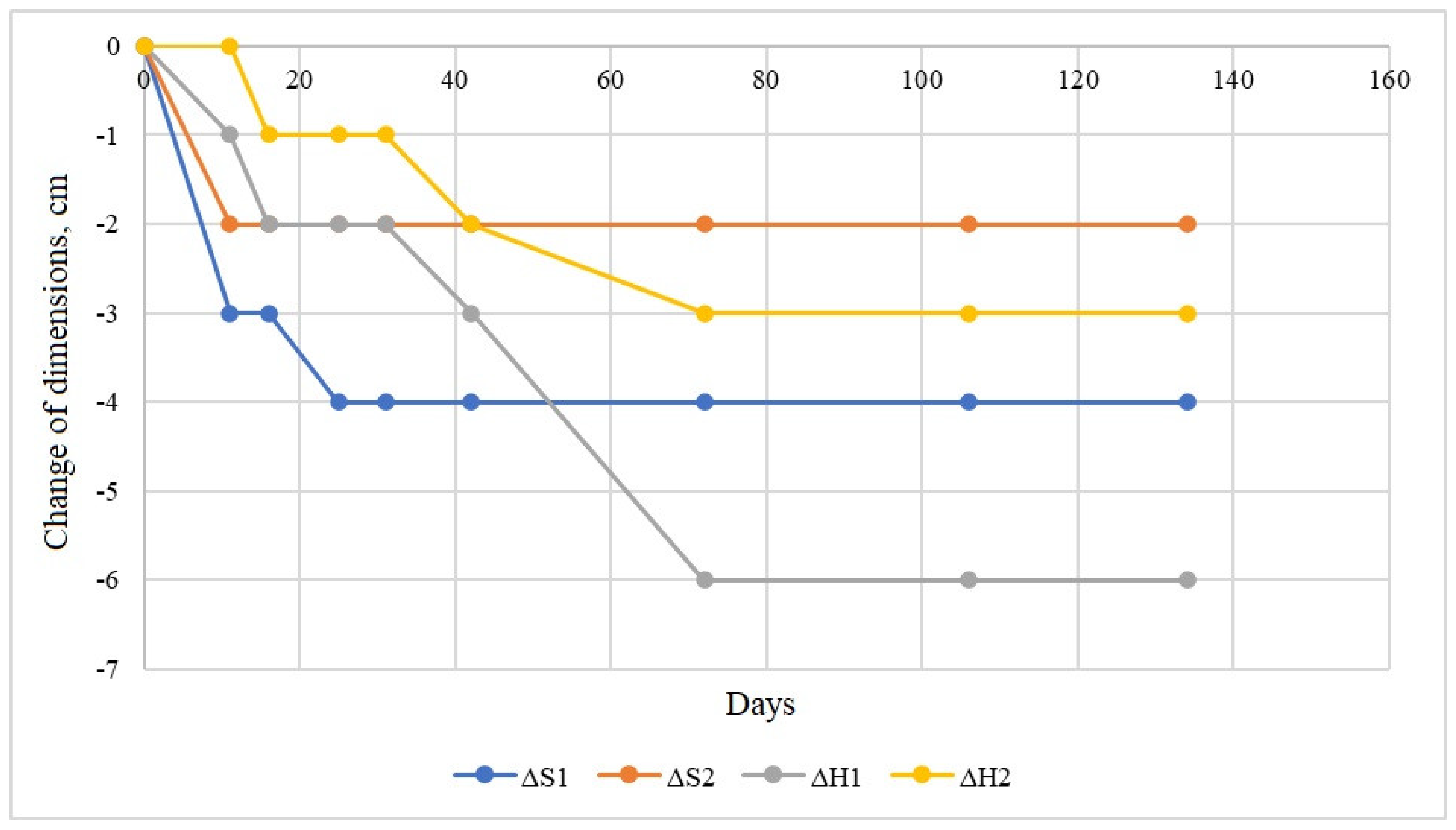
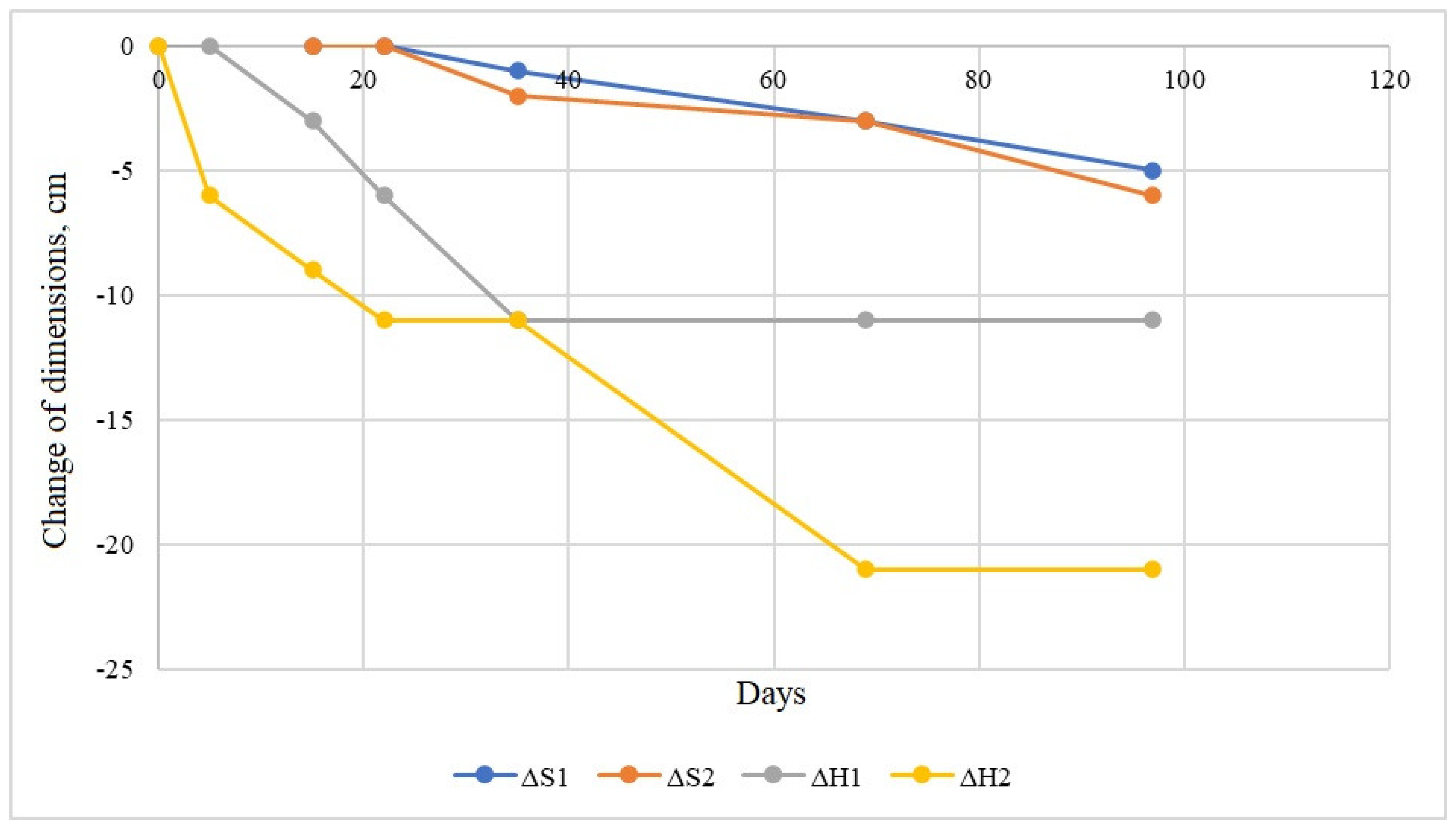
3.4. Convergence
Similarly to the roof delaminations and bolt loading, the correlation between convergence and distance between the control station and the roadway face is distinct. A reduction of the roadway dimensions was observed on convergence control stations no. 1–4 in close proximity to the roadway face, but for a significant time such phenomenon does not occur. This contrast with the case of convergence control station no. 5, where dynamic convergence growth is observed, due to the close proximity of the roadway face and unfavourable geological and mining conditions. Diagrams of the convergence values measured on subsequent convergence control stations are presented in
Appendix A.
4. Conclusions
Stability of the Bw-1n roadway, the first roadway driven by Bolter Miner machine in Polish coal mining industry, was constantly monitored using five periodic control stations, five convergence control station and numerous everyday control stations Stability monitoring comprises:
delamination monitoring using extensometers,
delamination monitoring using borescope,
delamination range monitoring using extensometric probes,
bolt loading monitoring using strain gauge bolts,
strength tests of roof rocks using penetrometer,
pull-out bolts tests,
convergence monitoring.
The main goal of stability monitoring in the Bw-1n roadway was conducted to prove safety of independent rock bolting support in conditions of Polish coal mining industry. Constant control of the monitoring system is also conducted to adapt designed support to existing geological and mining conditions. Regarding safety, monitoring system showed its relevance especially in sixth month of the project, when exceedance of allowed designed values observed helped to adjust support parameters and thus maintain stability and safety of the roadway. Adaptation to changing geological and mining conditions and parameters of the roadway was possible mostly because of the proper monitoring system.
Data gathered from numerous elements of the monitoring system allowed us to prove the safety and stability of the Bw-1n roadway. Analysis of this data showed proper interaction between the rock bolting and rock mass. During the nine months of roadway driving as well as another year of its existence it remained stable and safe.
The only problem identified during the project was delamination of the rock layers over the range of bolting conducted. However, they are present in very unfavorable geological conditions. The solution for this issue is application of long elastic bolts with length of 5.0 m. Furthermore, in this case, the bolting pattern was adjusted.
It was concluded that in future applications bolting pattern should be constantly analyzed and adjusted to current geological and mining conditions, as it was done in the project. It allowed to maintain proper level of safety by adapting to conditions.
According to the opinion of the expert in domain of roof bolting responsible for the project, independent roof bolting is possible to use in conditions similar to Bw-1n roadway, thus it is applicable in conditions of underground coal mines in Poland. However, constant monitoring of rock mass and support is necessary, similarly to the described case. The most important issue is constant adjustment of the bolting pattern, according to analysis of monitoring data gathered and opinion of the expert.
The possibility of application of a remote delaminations monitoring system was analyzed in the project. Such a solution, gathering and transmitting data in near-real time, can further improve level of safety and comfort of miners as well as provide thorough analysis of interaction between support and rock mass, which can help to improve design of the rock bolting support for another mine workings. However, no relevant data were gathered using this system. Although experience gained can help to improve the system to be used in another mine workings.
As the near-real time monitoring is becoming increasingly popular in mines and technologies of it are constantly developing, the introduction of such system in Polish coal mining industry is inevitable. It is important to introduce it in such a research project, where besides the safety issues, it can improve rock bolting support for Polish coal mines due to thorough data analysis.
Author Contributions
Conceptualization, A.D., P.K. and Z.R.; methodology, P.K. and J.J.; validation, D.J., A.D. and Z.R.; formal analysis, A.D.; investigation, P.K.; resources, T.S.; data curation, Z.R. and D.J.; writing—original draft preparation, P.K. and J.J.; writing—review and editing, D.J., T.S. and Z.R.; supervision, A.D.; project administration, A.D.; funding acquisition, A.D. All authors have read and agreed to the published version of the manuscript.
Funding
This research received no external funding.
Institutional Review Board Statement
Not applicable.
Informed Consent Statement
Not applicable.
Data Availability Statement
Not applicable.
Conflicts of Interest
The authors declare no conflict of interest.
Appendix A
Results of roof delaminations and convergence measurements.
Figure A1.
Roof delaminations measured using multilevel mechanical extensometer—periodic control station no. 2.
Figure A1.
Roof delaminations measured using multilevel mechanical extensometer—periodic control station no. 2.
Figure A2.
Roof delaminations measured using multilevel mechanical extensometer—periodic control station no. 3.
Figure A2.
Roof delaminations measured using multilevel mechanical extensometer—periodic control station no. 3.
Figure A3.
Roof delaminations measured using multilevel mechanical extensometer—periodic control station no. 4.
Figure A3.
Roof delaminations measured using multilevel mechanical extensometer—periodic control station no. 4.
Figure A4.
Roof delaminations measured using multilevel mechanical extensometer—periodic control station no. 5.
Figure A4.
Roof delaminations measured using multilevel mechanical extensometer—periodic control station no. 5.
- 2.
Convergence measurements
Figure A5.
Change of the roadway dimensions—convergence control station no. 1.
Figure A5.
Change of the roadway dimensions—convergence control station no. 1.
Figure A6.
Change of the roadway dimensions—convergence control station no. 2.
Figure A6.
Change of the roadway dimensions—convergence control station no. 2.
Figure A7.
Change of the roadway dimensions—convergence control station no. 3.
Figure A7.
Change of the roadway dimensions—convergence control station no. 3.
Figure A8.
Change of the roadway dimensions—convergence control station no. 4.
Figure A8.
Change of the roadway dimensions—convergence control station no. 4.
Figure A9.
Change of the roadway dimensions—convergence control station no.5.
Figure A9.
Change of the roadway dimensions—convergence control station no.5.
References
- Bigby, D. Coal Mine Roadway Support System Handbook. Research Report 229a; Rock Mechanics Technology Ltd.: Staffordshire, UK, 2004. [Google Scholar]
- Małkowski, P. Obudowa kotwowa wczoraj i dziś w aspekcie obowiązujących przepisów. Bezpieczeństwo Pr. I Ochr. Sr. W Górnictwie 2016, 11, 3–13. (In Polish) [Google Scholar]
- Kang, H. Support technologies for deep and complex roadways in underground coal mines: A review. Int. J. Coal Sci. Technol. 2014, 1, 261–277. [Google Scholar] [CrossRef] [Green Version]
- Li, C.H. Principles of rockbolting design. J. Rock Mech. Geotech. Eng. 2017, 9, 396–413. [Google Scholar] [CrossRef]
- Kabwe, E.; Wang, Y. Review on Rockburst Theory and Types of Rock Support in Rockburst Prone Mines. Open J. Saf. Sci. Technol. 2015, 5, 104–121. [Google Scholar] [CrossRef] [Green Version]
- Indian Bureau of Mines. Cable Bolting Practices in Underground Mines; Bulletin No. 42; Publication Cell: Nagpur, India, 2002. [Google Scholar]
- Moyo, T.; Stacey, T.R. Mechanisms of rockbolt support in jointed rock masses. In Deep Mining 2012; Potvin, Y., Ed.; Australian Centre for Heomechanics: Perth, Australia, 2012; ISBN 978-0-9806154-8-7. [Google Scholar]
- Paghdar, D.K.; Patel, H.R.; Kashiyani, B.K.; Patel, H.M. Recent Trends on Rock Bolting in Tunnel Construction. IJSRD Int. J. Sci. Res. Dev. 2013, 1, 2118–2121. [Google Scholar]
- Skrzypkowski, K. Evaluation of Rock Bolt Support for Polish Hard Rock Mines. In E3S Web of Conferences 35; EDP Sciences: Ulis, France, 2018. [Google Scholar] [CrossRef] [Green Version]
- Majcherczyk, T.; Małkowski, P.; Niedbalski, Z. Stateczność chodników równoległych w samodzielnej obudowie kotwowej. Przegląd Górniczy 1999, 10, 16–25. (In Polish) [Google Scholar]
- Nierobisz, A. Kotwienie–historia, teraźniejszość oraz przyszłość. Pr. Nauk. GIG Górnictwo I Sr. 2010, 2/1, 184–203. (In Polish) [Google Scholar]
- Skrzypkowski, K.; Korzeniowski, W.; Zagórski, K.; Zagórska, A. Modified Rock Bolt Support for Mining Method with Controlled Roof Bending. Energies 2020, 13, 1868. [Google Scholar] [CrossRef] [Green Version]
- Majcherczyk, T.; Małkowski, P.; Niedbalski, Z. Stand-and-roof-bolting support: An effective way of roadway reinforcement. In Proceedings of the 22nd World Mining Congress & Expo, Istanbul, Turkey, 11–16 September 2011; Eskikaya, S., Ed.; Aydogdu Ofset: Ankara, Turkey, 2011; pp. 279–285. [Google Scholar]
- Rak, Z.; Stasica, J.; Burtan, Z. Skuteczne rozwiązania w systemie wysokiego kotwienia dla wzmacniania obudowy podporowej—Effective solutions in the long rock bolting system for strengthening the standing suport. Zesz. Nauk. Inst. Gospod. Surowcami Miner. I Energią PAN 2017, 101, 101–116. (In Polish) [Google Scholar]
- Batrancea, I.; Batrancea, L.; Nichita, A.; Gaban, L.; Masca, E.; Fatacean, G.; Moscviciov, A. An Econometric Approach on Production, Costs and Profit in Romanian Coal Mining Enterprises. Econ. Res. Ekon. Istraživanja 2019, 32, 1019–1063. [Google Scholar] [CrossRef] [Green Version]
- Walke, D.V.; Yerpude, R.R. Significance of strata monitoring instruments in roof fall risk assessment of an underground coal mine. Int. J. Sci. Res. Publ. 2015, 5, 1–8. [Google Scholar]
- Kalinowski, P.; Długosz, O.; Kamiński, P. Digital Twin of the Mining Shaft and Hoisting System as an Opportunity to Improve the Management Processes of Shaft Infrastructure Diagnostics and Monitoring. In Data Visualization; InTech Open: London, UK, 2021. [Google Scholar] [CrossRef]
- Bigby, D.; MacAndrew, K.; Hurt, K. Innovations in mine roadway stability monitoring using dual height and remote reading electronic telltales. In Proceedings of the 2010 Coal Operators’ Conference, Wollongong, Australia, 11–12 February 2010; Aziz, N., Kininmonth, B., Eds.; The University of Wollongong Printery: Wollongong, Australia, 2010. [Google Scholar]
- Bosikov, I.I.; Klyuev, R.V.; Khetagurov, V.N.; Azhmukhamedov, I.M. Development of methods and management tools aerogasdynamics processes at mining sites. Sustain. Dev. Mt. Territ. 2021, 1, 77–83. [Google Scholar] [CrossRef]
- Małkowski, P.; Niedbalski, Z. Monitoring wyrobisk korytarzowych jako podstawa weryfikacji metod projektowych i przyjętego schematu obudowy. Prz. Gór. 2019, 10, 53–65. (In Polish) [Google Scholar]
- Majcherczyk, T.; Niedbalski, Z.; Ulaszek, A. Roadway stability evaluation on the basis of modern monitoring of displacement. Studia Geotech. Et Mech. 2015, 37, 45–52. [Google Scholar] [CrossRef] [Green Version]
- Niedbalski, Z.; Małkowski, P.; Majcherczyk, T. Monitoring of stand-and-roof-bolting support: Design optimization. Acta Geodyn. Et Geomater. 2013, 10, 215–226. [Google Scholar] [CrossRef] [Green Version]
- Małkowski, P.; Niedbalski, Z.; Majcherczyk, T.; Bednarek, Ł. Underground monitoring as the best way of roadways support design validation in a long time period. Min. Miner. Depos. 2020, 14, 1–14. [Google Scholar] [CrossRef]
- Majcherczyk, T.; Małkowski, P.; Niedbalski, Z. Badania obciążeń obudowy w wybranych wyrobiskach korytarzowych. Górnictwo I Geoinżynieria 2005, 29, 289–298. (In Polish) [Google Scholar]
- Majcherczyk, T.; Niedbalski, Z.; Małkowski, P. Measurements of roof support load in headings: In situ research. In International Mining Forum, 2007; Sobczyk, E., Kicki, J., Eds.; Taylor & Francis Group: London, UK, 2017; pp. 37–46. [Google Scholar]
- Małkowski, P. Zarządzanie monitoringiem zagrożeń w górnictwie (Management of mining monitoring systems). Inż Miner. 2017, XVIII, 215–224. (In Polish) [Google Scholar] [CrossRef]
- Prusek, S. Determination of the size of the fracture zone around a road working based on the results of underground convergence measurements and numerical modelling. In International Mining Forum, 2007; Sobczyk, E., Kicki, J., Eds.; Taylor & Francis Group: London, UK, 2007; pp. 125–136. [Google Scholar]
- Małkowski, P.; Niedbalski, Z.; Majcherczyk, T. Endoscopic method of rock mass quality evaluation–new experiences. In Proceedings of the 42nd US rock mechanics symposium and 2nd US-Canada Rock Mechanics Symposium, San Francisco, CA, USA, 29 June–2 July 2008; pp. 1–7. [Google Scholar]
- Sosna, K.; Brož, M.; Vaněček, M.; Polák, M. Exploration of a granite rock fracture system using a TV camera. Acta Geodyn. Geomater. 2009, 4, 453–463. [Google Scholar]
- Song, G.; Li, W.; Wang, B.; Ho, S. A Review of Rock Bolt Monitoring Using Smart Sensors. Sensors 2017, 17, 776. [Google Scholar] [CrossRef] [PubMed] [Green Version]
- Huo, L.; Wang, B.; Chen, D.; Song, G. Monitoring of Pre-Load on Rock Bolt Using Piezoceramic-Transducer Enabled Time Reversal Method. Sensors 2017, 17, 2467. [Google Scholar] [CrossRef]
- Yu, J.; Lee, J. Smart Sensing Using Electromagnetic Waves for Inspection of Defects in Rock Bolts. Sensors 2020, 20, 2821. [Google Scholar] [CrossRef]
- Singh, R.; Singh, A.K.; Mandal, P.K.; Singh, M.K.; Sinha, A. Instrumentation and monitoring of strata movement during underground mining of coal. Minetech 2004, 25, 12–26. [Google Scholar]
- Szurgacz, D.; Brodny, J. Application of a roof support monitoring system for analysis of work parameters of a powered longwall system. In E3S Web of Conferences; EDP Sciences: Ulis, France, 2019. [Google Scholar] [CrossRef]
- Małkowski, P.; Ostrowski, Ł. Convergence monitoring as a basis for numerical analysis of changes of rock-mass quality and Hoek-Brown failure criterion parameters due to longwall excavation. Arch. Min. Sci. 2019, 64, 93–118. [Google Scholar] [CrossRef]
- Małkowski, P.; Majcherczyk, T.; Niedbalski, Z. Convergence of roadways calculated with the help of numerical models and its revision with research in the field. Kwart. Górnictwo I Geoinżynieria Akad. Górniczo-Hut. 2008, 1, 199–215. (In Polish) [Google Scholar]
- Walentek, A. Analysis of the applicability of the convergence control method for gateroad design based on conducted underground investigations. Arch. Min. Sci. 2019, 64, 765–783. [Google Scholar] [CrossRef]
- Czarnecki, Z.; Niedbalski, Z.; Nita, Ł.; Śpiechowicz, M. Zasięg strefy spękań w otoczeniu wyrobiska wykonanego w samodzielnej obudowie kotwowej. Prz. Gór. 2021, 77, 48–58. (In Polish) [Google Scholar]
| Publisher’s Note: MDPI stays neutral with regard to jurisdictional claims in published maps and institutional affiliations. |
© 2021 by the authors. Licensee MDPI, Basel, Switzerland. This article is an open access article distributed under the terms and conditions of the Creative Commons Attribution (CC BY) license (https://creativecommons.org/licenses/by/4.0/).


 ,
, 


