
Effects of Degradation in Textolite Elements of Damaged Surge Arresters
by
 , and
, and
Hubert Śmietanka
1, 
Przemysław Ranachowski
2,
Zbigniew Ranachowski
2,*,
Krzysztof Wieczorek
3 and
Stanislav Kudela, Jr.
4 1
Institute of Power Engineering-Research Institute, Mory 8, 01-330 Warsaw, Poland
2
Institute of Fundamental Technological Research Polish Academy of Sciences, Pawinskiego 5B, 02-106 Warsaw, Poland
3
Faculty of Electrical Engineering, Wroclaw University of Science and Technology, Wyb. Wyspiańskiego 27, 50-370 Wroclaw, Poland
4
Institute of Materials and Machine Mechanics, Slovak Academy of Sciences, Dubravska Cesta 9/6319, 845 13 Bratislava, Slovakia
*
Author to whom correspondence should be addressed.
Energies 2022, 15(10), 3643; https://0-doi-org.brum.beds.ac.uk/10.3390/en15103643
Submission received: 24 March 2022
/
Revised: 10 May 2022
/
Accepted: 11 May 2022
/
Published: 16 May 2022
(This article belongs to the Topic Power Distribution Systems)
Abstract
:The aim of this work was to investigate the effects of the currents flowing through surge arresters on the internal insulating textolite structure. The samples were removed from high-voltage arresters that were taken out of service due to malfunction or failure. Discharge (short-circuit) currents of diverse intensities and durations caused degradation effects of varying degrees of advancement in the material of the tested elements. The samples were examined using microscopic methods. The use of the microanalysis technique EDS (energy-dispersive X-ray spectroscopy) made it possible to register changes in the elemental composition of the surface layer of the textolite materials, along with the intensification of the degradation effects. It was found that the high discharge current flows were subject to melting, charring and even burning of the organic adhesive. These effects caused serious changes in the content of elements in the top layer of the textolite and were the cause of a reduction in the service life, durability and reliability of the surge arresters. It was shown that the textolite materials had insufficient resistance to the effects of the emergency operation of the arresters after moisture ingress, which was a consequence of unsealing of the housing. A solution to this problem proposed by the authors could be the use of silicone elastomer as a covering of the textolite internal structure of surge arresters.
1. Introduction
The durability and reliability of surge arresters determine the effective overvoltage protection of power networks. The current requirements concerning the high reliability of electrical devices and instruments entail the need for the protection of all equipment working in electrical networks against voltage surges caused by severe lightning, switching operations or other factors [1,2,3,4,5,6,7]. Surges cannot be predicted and avoided. Overvoltages appearing and propagating in networks can result in hazardous levels of voltage stresses. They can damage the insulation of equipment or other components of the electricity network and cause highly expensive disruptions in their operation. While the devices installed in electrical substations should operate faultlessly, they should also operate under disturbance conditions. Especially sensitive to overvoltages are transformers, which play a key role in power systems; therefore, they have to be particularly protected.
Various methods of overvoltage limitation are applied, depending on the parameters of the occurring surges and properties of the protected equipment [8,9,10]. For this purpose, surge arresters are commonly used to protect transmission and distribution systems. The most popular type of gapless devices is surge arresters containing ZnO metal–oxide varistors (metal–oxide surge arrester (MOSA)). MOSAs are very effective voltage-limiting devices due to the highly nonlinear voltage–current characteristics of the varistors and rapid conduction response for high-voltage surges. Their design solutions, principles of operation, and issues of long-time exploitation and testing methods were presented in a cross-sectional way in multiple studies [1,11]. MOSAs have been enjoying continued interest from researchers for many years and papers on a wide range of issues related to these devices are constantly being published. A historical overview of the invention, development and growing use of gapless surge arresters is presented in several works [1,5,11]. The issue of work and effectiveness of the devices in various electrical conditions and systems is frequently undertaken in various studies and is widely researched [3,4,6,7,12,13]. Another question often found in publications on MOSAs concerns operational problems related to the performance and reliability of devices [7,13,14,15,16,17]. The diagnostics of surge arresters is also one of the important and frequently discussed issues in the literature [1,11,18,19].
There are many causes of damage to surge arresters during operation. They are well recognised on the basis of many years of operational experience and are similarly presented in various publications [1,13,17,20,21,22]. The following reasons for the damage should be mentioned here:
- Ingress of moisture into the interior, e.g., as a result of manufacturing defects or degradation of seals;
- Exceeding the peak value and/or duration of the discharge current of lightning or switching overvoltages;
- Improper selection of the surge arrester to the network conditions, e.g., too low continuous operating voltage;
- Damage to or short-circuit of one of the arrester’s sections or varistors, e.g., as a result of contamination or manufacturing defects;
- Strong uneven pollution of the outer surface of the arrester’s housing;
- Occurrence of overvoltages of duration and peak value greater than the guaranteed resistance to such effects (at mains frequency).
Many years of operating experience, as well as the authors’ practice, confirm that moisture ingress, worsened by pollution, is by far the most common cause of degradation and damage to surge arresters [1,15,16,17,19,20,21,23,24]. Moisture ingress into the interior of a surge arrester may result from improper design or manufacturing, material defects in the seals, improper assembly, damage or the deterioration of sealing materials, such as rubber over time.
The moisture absorption in an arrester can result in increased leakage current, typically in the range of milliamperes [17,18,25]. This can consequently lead to overheating of the ZnO varistors, causing the temperature of the entire arrester to increase. Moisture inside devices plays a significant role in the degradation process of varistors. Moreover, this increases the thermal heating (risk of thermal instability) and leakage current and, what is worse, causes discharges. Consequently, a defective arrester is unable to work properly when an electrical surge occurs [7,11,26]. Moisture ingress may result in its condensation and change in the protection level, as well as the capability for energy dissipation. Typically, the level of humidity can increase up to 40–50%. At high humidity levels, there is even the possibility of condensation during temperature changes. The moisture layer on the internal parts of surge arresters can initiate internal flashover [11,15,16,17,19,23].
Typical surge arresters have a closed construction and have a homogeneous polymer housing around the internal components. The varistor pile is enclosed in a tube-shaped, shield-centring element, usually made of textolite TSE [1,11]. The benefit of such a design is its high mechanical durability with relatively low mass, while the drawback is poor cooling of the varistors. In addition, if no suitable countermeasures are provided in the design, there is a risk of exposing the polymeric material to the effect of incomplete discharges, which may occur between the inner wall of the shield-centring element and the varistor stack under the influence of external contamination. Long-term practice demonstrated that short-circuit currents cause partial discharges inside surge arresters. As a result, inside the structure of surge arresters, the local temperature rises high. It mainly causes degradation of the textolite material, which is used for the construction of internal elements.
For years, numerous studies on the negative impact of moisture on the functioning of surge arresters have been carried out. The effects of the degradation of varistors were also widely studied, in which the authors also participated [27,28]. The problems connected with the functioning of varistors are generally well recognised. However, there is no in-depth research on the effects of the degradation of the internal elements of surge arresters made of glass–epoxy laminate, just like glass textolite TSE. Such studies have been carried out by the authors for several years and are focused on the analysis of the effects of flashovers on the surfaces of various elements made of textolite [29]. The degradation effects caused by such discharges are often encountered in the case of the failure of surge arresters. This seems to be a consequence of the properties of the textolite itself, which shows insufficient resistance to the effects of emergency operation of the arrester after moisture ingress, which is a result of unsealing of the housing.
2. Subject and Methodology of Tests
This paper presents the results of research on the stages of material degradation of the textolite elements of surge arresters. The effects occur under the influence of the flow of strong short-circuit currents. As it was mentioned, the authors have been involved in similar research for many years [29]. The tested elements, mainly bushing supports, were made of a glass–epoxy laminate, which is referred to as TSE glass textolite. The supports constituting the subject of the research were dismantled from various high-voltage (HV) surge arresters, through which discharge (short-circuit) currents of various intensities and durations flowed. They caused clear degradation effects of varying degrees of advancement in the material of the textolite elements, which could be observed and documented. The surge arresters, from which the elements for testing were obtained, were taken out of service due to a malfunction or failure.
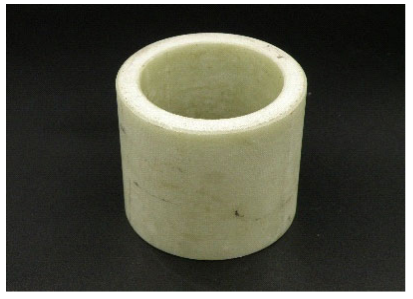
Typical textolite bushing support without degradation effects obtained from a 110 kV surge arrester that was removed from operation is shown in Figure 1. It had a height of 72 mm, an outer diameter of 80 mm and a hole diameter of 60 mm. It served as a reference sample and material for the remaining samples with very different degrees of degradation.
To conduct the research, microscopic techniques were mainly used, i.e., optical microscopy (MO) and scanning electron microscopy (SEM). The optical microscopy method was used primarily for the preliminary inspection of the samples’ surfaces and enabled quick comparative tests to be conducted. At low magnification (on the order of 50 times), significant areas of the surface were observed, making it possible to quickly assess the nature and intensity of the degradation processes. At the same time, it was possible to find interesting fragments of each sample surface, which were then examined using scanning electron microscopy. The use of the vacuum technique made it possible to make detailed observations in a wide range of magnifications ranging from several dozen to even about 1000 times without the need to spray the samples with a conductive medium. The use of both microscopic techniques made it possible to research and document the effects of degradation of the top layer of the material on micro- and mesoscales. The microanalysis technique EDS (energy-dispersive X-ray spectroscopy) made it possible to register and document changes in the elemental composition, i.e., the content of the elements of the surface layer of the textolite materials, along with the intensification of the degradation effects. Generally, the use of EDS allowed for a quick qualitative and quantitative determination of the elemental composition of the areas of interest, starting with boron (atomic number 5) in carefully selected places showing the representative nature of the degradation processes. In order for the test results to be reliable and fully comparable, the analysis had to be carried out on the same areas of the surface. For all samples, irrespective of the degree of degradation, we chose an area of 4.0 mm2. For each sample with a given degree of degradation, EDS tests were performed at four different points on the surface. Comparative studies showed that a sufficient picture of the possible dispersion of parameters of the tested sample surface could then be obtained.
Glass textolite TSE, which was the subject of the research, shows good dielectric properties with high resistance to electric breakdown. It also demonstrates, as for a laminate of this type, significant resistance to elevated temperatures, i.e., about 180 °C. The support of the material, of the nature of a highly laminated composite, is prepared as bundles of fibres made of special ECR glass in the form of a densely woven weave. A typical composition of this type of glass includes about 60% SiO2, more than 20% CaO, a dozen or so per cent of Al2O3 and a lower content of other metal oxides [30]. A significant amount of calcium in the elemental composition results from the use of CaCO3 as a flux and stabiliser in the glass batch. Aluminium comes from the oxide, which improves the chemical resistance of this special-purpose glass. The presence of mobile sodium ions Na+ (e.g., from a flux like Na2CO3) is minimised. Applied glass fibres have a diameter from a few to approximately 20 µm [31]. The adhesive (binder) of the laminate constitutes an epoxy resin. It is obvious that the heat resistance of which, as an organic polymer, is much lower than that of the fibreglass textile support.
3. Tests Results
There were tested 14 samples, which came from nine overvoltage limiters, that were taken out of service in the high voltage mains of 110 kV (in an exceptional case 220 kV). All tested devices worked at transformer substations, in overhead conditions in the central regions of the country, in practically the same climatic conditions and very similar low pollution surroundings (zone I) [32]. It can be assumed that there were no differences in environmental and contamination conditions between the workplaces of the devices. As previously mentioned, the subject of this research was the nature and degree of advancement of the degradation processes, as well as the elemental composition of the samples’ surfaces.
3.1. The Reference State
The reference sample, which may be marked first, for the research on the effects of degradation of the textolite material of surge arresters was the bushing support presented in Figure 1, which was obtained from an operated device for the 110 kV network. The arrester was decommissioned after a dozen or so years of operation. Small deviations from proper operation (too high leakage currents) resulted from the work of the varistor stack. No traces of discharge (short-circuit) currents, resulting in heat generation, were found inside the device or on the tested support. This made it possible to treat the tested material as a reference state in relation to the textolite of other samples of the same or very similar elements. They came from damaged HV surge arresters and showed signs of degradation with a highly different degree of advancement. It should be emphasised that often within a sample or several samples from the same, damaged surge arrester, there was a significant variation in the intensity of the degradation effects of the textolite material. Moreover, these effects occurred in places where discharges occurred in various sectors of the examined elements.
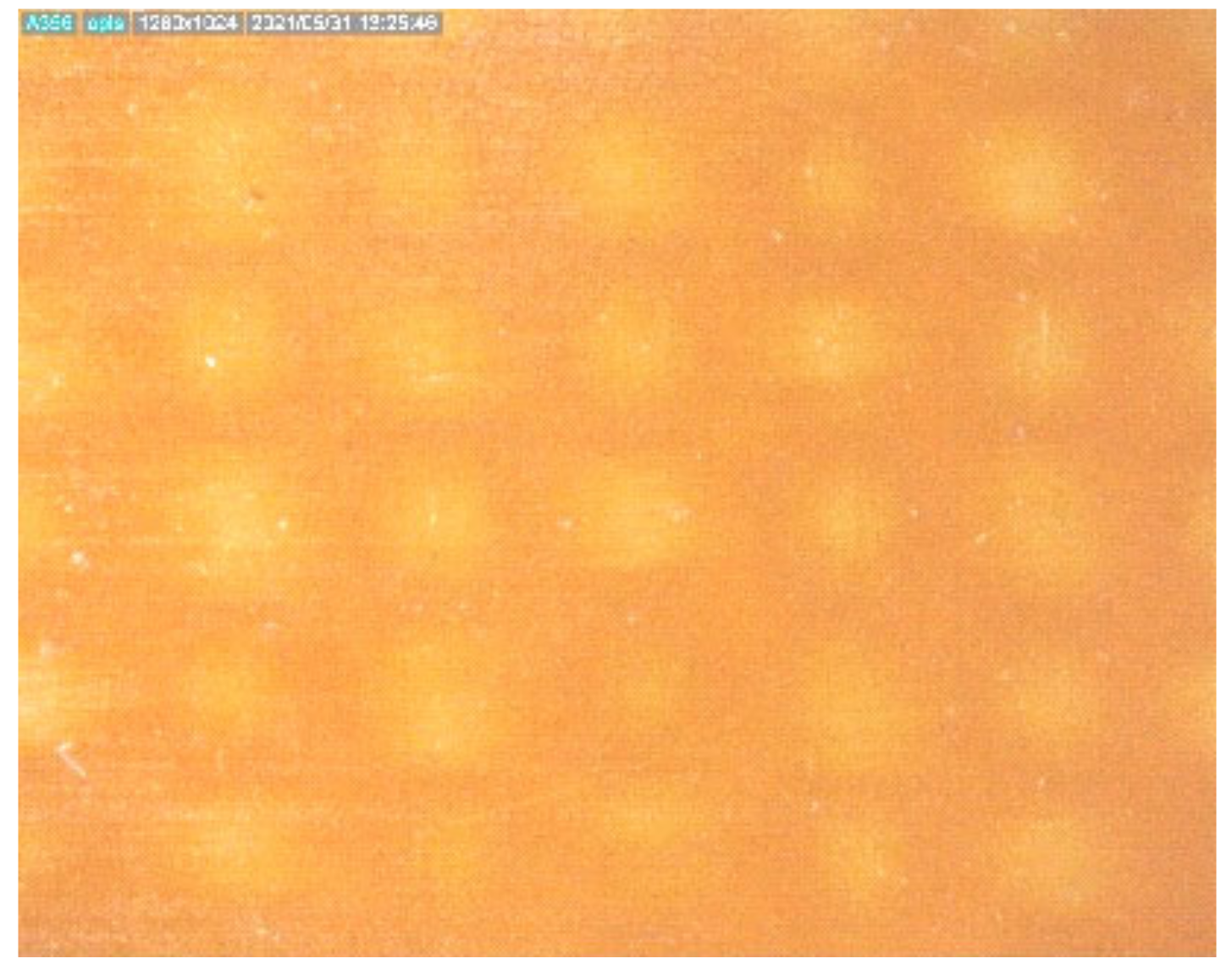
The textolite support had a bright colour and was carefully examined. Figure 2 presents the microscopic image (MO) of the material. The photo shows the fibre bundles of the textile support (roving), but they were covered with a layer of transparent epoxy resin and were located under the surface of the textolite material. The surface of the laminate was quite smooth and free of cracks, which was confirmed using an SEM investigation.
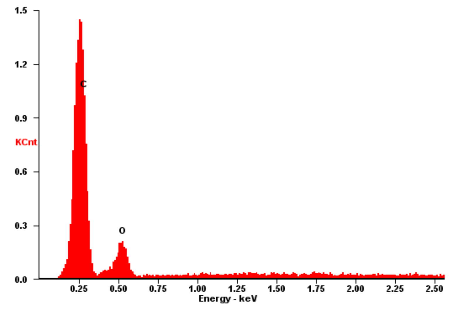
Figure 3 shows the results of the EDS test on the reference surface of the textolite material, with the determined elemental composition. Only epoxy resin, i.e., the binder of the laminate, was present in the top layer of the material. EDS measurements, which were carried out in four different areas, showed only a slight spread of the results. The laminate surface contained 66.0 ÷ 71.5% of carbon (C) and 28.5 ÷ 31.0% of oxygen (O) by weight, omitting the content of hydrogen (H), which could not be analysed using the EDS technique. The elements present in the textile support, namely, silicon (Si) and metals, were not registered because were covered with a top layer of the organic resin.
3.2. Light Degradation
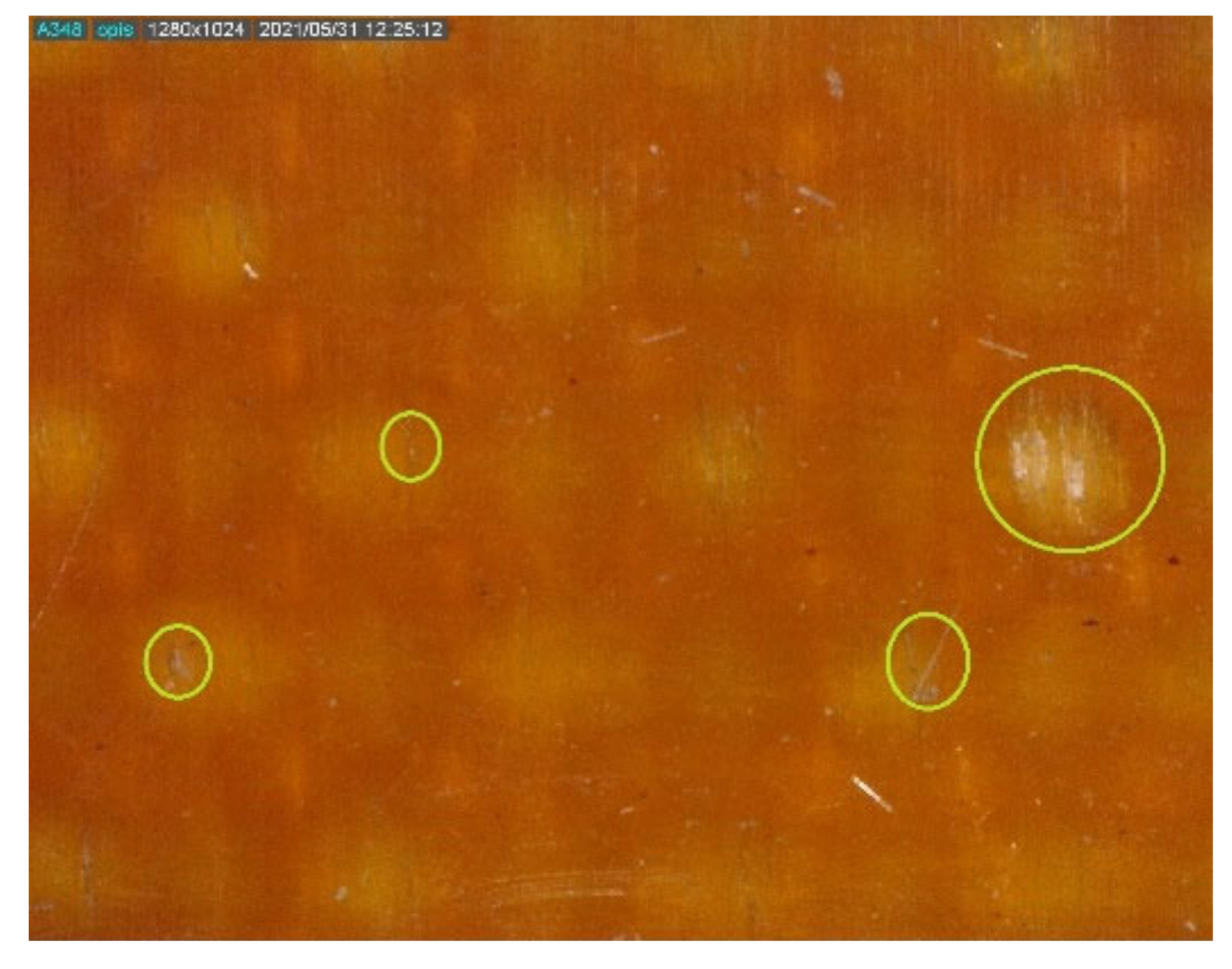
Figure 4 shows the textolite material of the element from the operated HV surge arrester, in which there were weak degradation effects, mainly slight carbonisation of the epoxy resin. The device was removed from service in a 110 kV system after almost 10 years of operation due to increased leakage currents. Some depressurisation of the surge arrester structure and the presence of moisture were found inside. However, there were no strong discharges inside the device. The MO photo demonstrated a change in the colour of the textolite material of the element, which had clearly darkened. Moreover, small fragments of the textile support appeared on the surface, which resulted from the local melting of the epoxy resin on the top layer of the material. There also appeared lesser single cracks in the resin that were several dozen micrometres long.
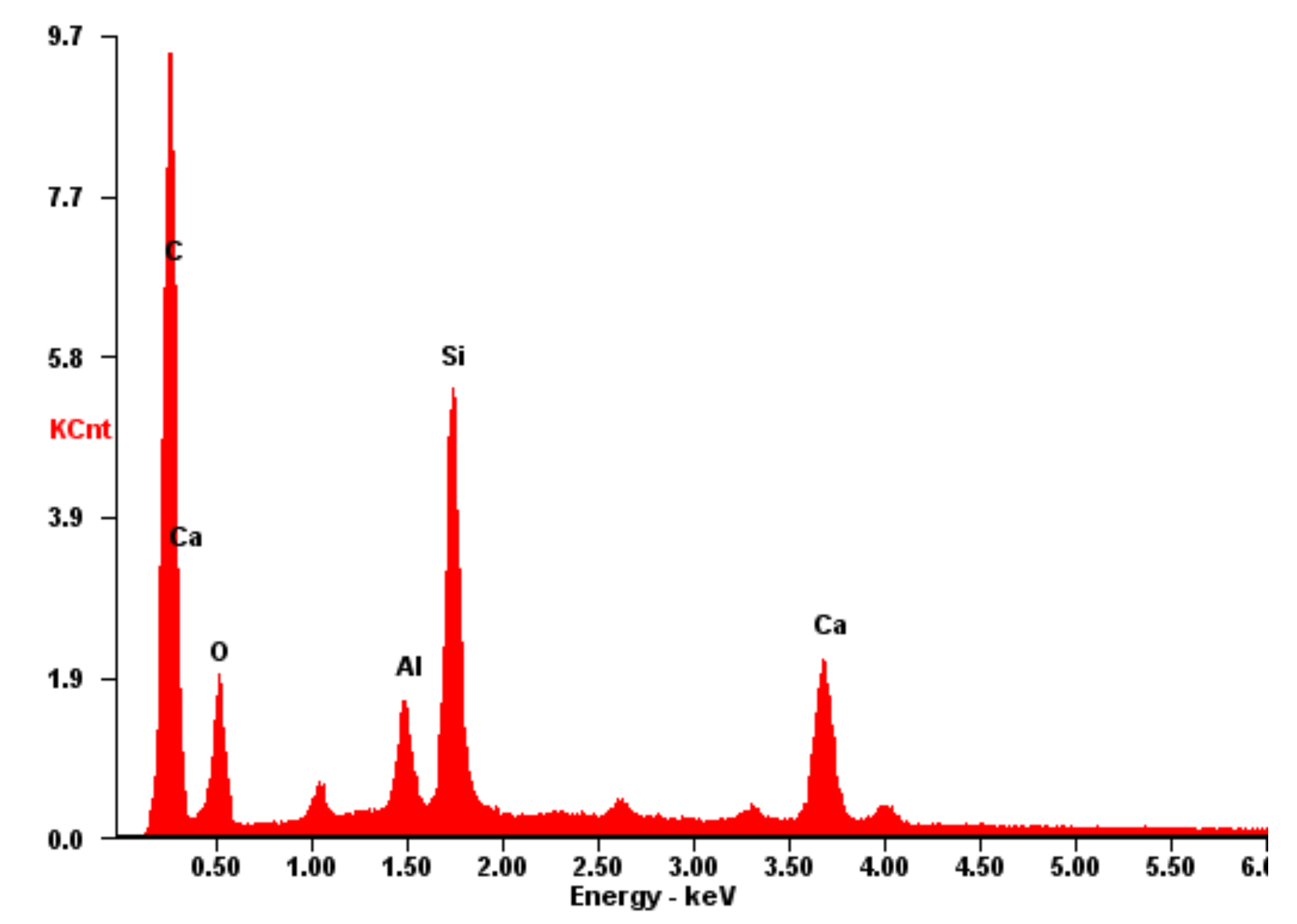
EDS measurements (at four different points) of the surface of the samples, showing a relatively slight degree of degradation, revealed some variation in the elemental composition of the surface. The carbon content practically did not change in relation to the reference sample and amounted to 67.0 ÷ 69.4%. The amount of oxygen slightly decreased to the level of 27.1 ÷ 28.3%. On the other hand, there were registered elements from the glass fibres of the textile support, which appeared on the surface of the material: calcium (Ca) at the level of 1.5 ÷ 2.4%, silicon (Si) at over 1.0% and aluminium (Al) in the order of tenths of a per cent (Figure 5 and Table 1).
3.3. Clear Degradation
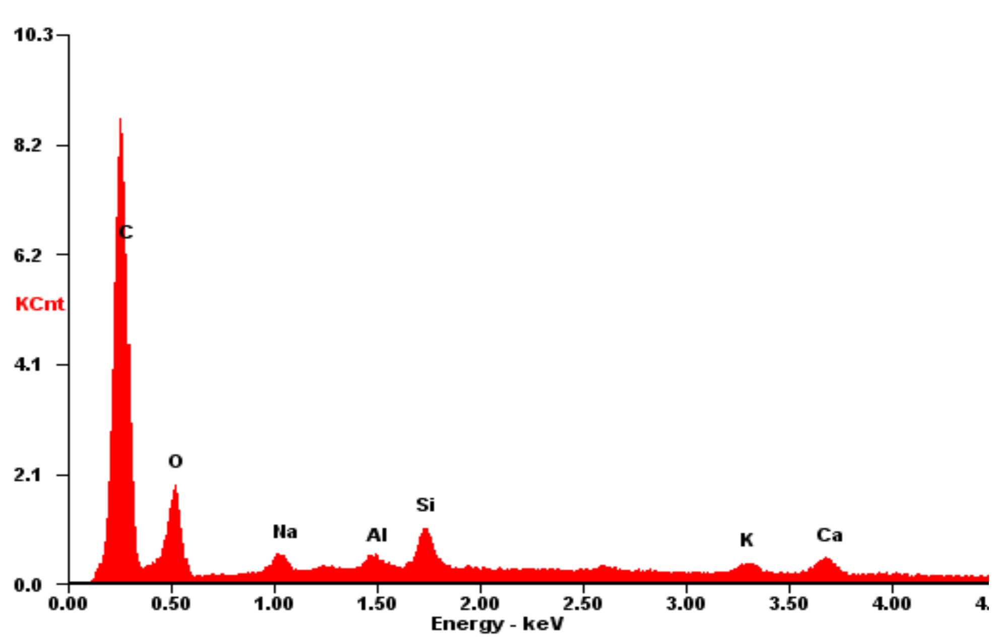
Figure 6 shows the MO image of the material structure of a textolite support from a decommissioned surge arrester with clear degradation effects. Due to the high increase in the value of leakage currents, the three surge arresters, which were operating in various phases of a 110 kV system at the transformer substation, were dismantled after about 10 years of operation. The cause of the malfunction was a loss of tightness of the devices. All three elements were disassembled to obtain test samples. As a result of the flow of discharge currents inside the surge arresters, the local temperature increased significantly. Consequently, in some areas of the tested elements, the organic epoxy resin was significantly carbonised. This was evidenced by the change in the colour of the material to an intense brown. There were several bundles of fibres from the textile support, which appeared on the surface of the material as a result of melting the top layer of the epoxy resin. Moreover, on the surface of the material, there was a network of small cracks in the epoxy resin, which are clearly visible in Figure 7.
EDS analysis of the textolite material with clearly visible degradation effects (Figure 8) documented the increase in the share of the textile support in the elementary composition of the material surface. The carbon content decreased by a few per cent to the level of 64.0 ÷ 65.7%. The amount of oxygen also slightly decreased to 26.3 ÷ 27.1%. At the same time, the amount of silicon increased to approximately 2.5%, calcium to between 2.0 and 3.0%, and aluminium to above 1.0%. Other components of the glass also appeared in a small amount, namely, the alkali metals sodium (Na) and potassium (K).
3.4. Advanced Degradation
Figure 9 and Figure 10 show the material of the textolite support from an HV surge arrester, which was removed from service as a result of damage. The failure of the device, which was operating at a 220 kV transformer substation, was a consequence of the device unsealing at the bottom fixing device and the penetration of moisture after over a dozen years of operation. The discharge current flows caused a significant increase in the local temperature inside the device. Taking into account the thermal resistance of the material, it can be estimated that it exceeded 200 °C locally. As a consequence, this led some areas of the textolite element to show degradation effects that could be described as advanced. Nevertheless, depending on the intensity and duration of the discharge currents, and thus the temperature generated, there were significant differences in the images of microstructures and the degree of degradation of the sample material. There were areas where the carbonisation process of the epoxy resin reached a high level. This was evidenced by the change in the laminate colour to intense brown. The top layer was melted to such an extent that the characteristic bright bundles of fibres from the textile support were quite numerous on the surface of the material. They were clearly visible in both the MO images (Figure 9) and the SEM pictures (Figure 10). The surface of the strongly melted and significantly charred resin in the top layer of the tested sample was cracked.
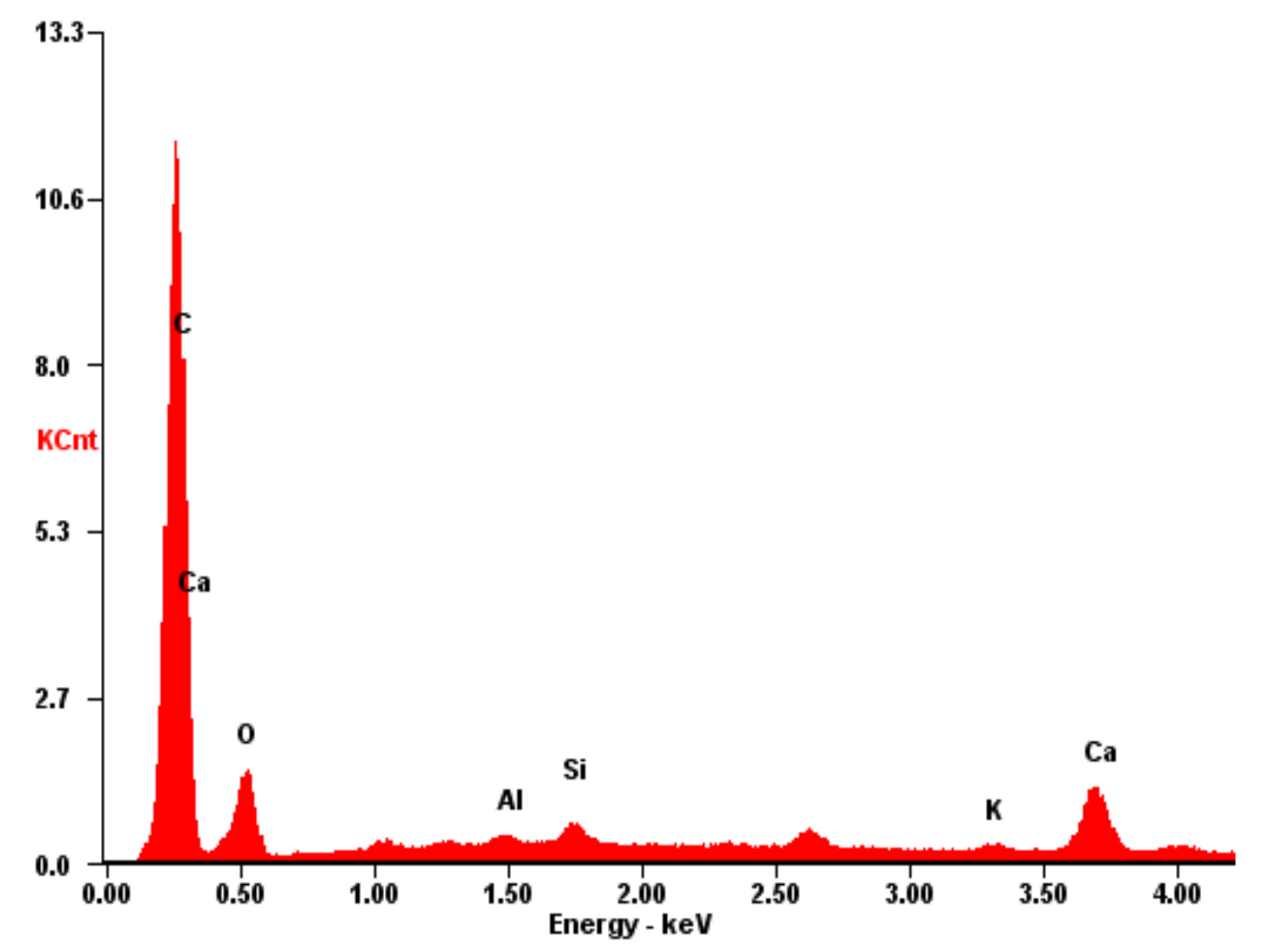
The results of the EDS tests in the areas with advanced degradation effects clearly showed a further, significant increase in the share of the textile support in the elemental composition of the material surface (Figure 11). Carbon content was between 60.7% and 62.7% and the oxygen contribution, in the range of 22.8% ÷ 25.0%, decreased by a few percentage points. This demonstrated a significant loss of organic epoxy resin in the top layer of the textolite material. At the same time, the amounts of the elements present in the glass fibres of the support increased: silicon to 3.9% ÷ 5.4%, calcium to 3.3% ÷ 4.2% and aluminium to a level between 1.0% and 2.0%.
3.5. Strong Degradation
As a result of the passage of discharge currents, a large temperature increase in the surge arresters can occur locally. Taking into account the degree of damage to one of the textolite elements that were obtained for testing, it could be as high as about 300 °C. This was evidenced by the tests that were applied to a bushing support removed from a damaged HV surge arrester. The failure of the device that was used only a few years at a 110 kV electrical substation was probably due to a manufacturing defect or assembly error and damage to the seal at the fixing device of the arrester. As a consequence, moisture ingress and a failure occurred after an unexpectedly short period of operation. Strongly advanced degradation effects were observed inside concerning various elements of the device, including varistors.
High carbonisation and significant melting of the epoxy resin occurred on the laminate surface, the colour of which changed to dark brown and, in places, black. At the same time, it was significantly cracked. Bundles of fibres from the textile support were clearly visible on the surface of the material (Figure 12). In particular, intense degradation was observed in the edge part of the textolite sample, next to the edge. There, the heavily charred resin was locally burned out almost completely and the textile support was exposed (Figure 13).
There were so many fibre bundles of the textile support on the surface of the material sample that the elements from glass constituted a significant component in the elementary composition of the top layer of the laminate. The EDS analysis of fragments of the textolite material in the areas with intensified degradation effects clearly showed a further, clear increase in the share of fibreglass support in the elemental composition of the laminate surface (Table 2 and Figure 14). Both the carbon content between 56.7% and 60.5% and the oxygen content in the range of 21.9% ÷ 23.6% were further slightly decreased. At the same time, the amount of silicon significantly increased to 6.7% ÷ 8.4%, calcium increased to 4.6% ÷ 8.0% and aluminium increased to a level between 2.0% and 3.0%. On the EDS spectrum (Figure 14), they were very visible. Thus, the weight fraction of elements derived from the glass was already a dozen or so per cent, not counting the oxygen part.
3.6. Very Strong Degradation
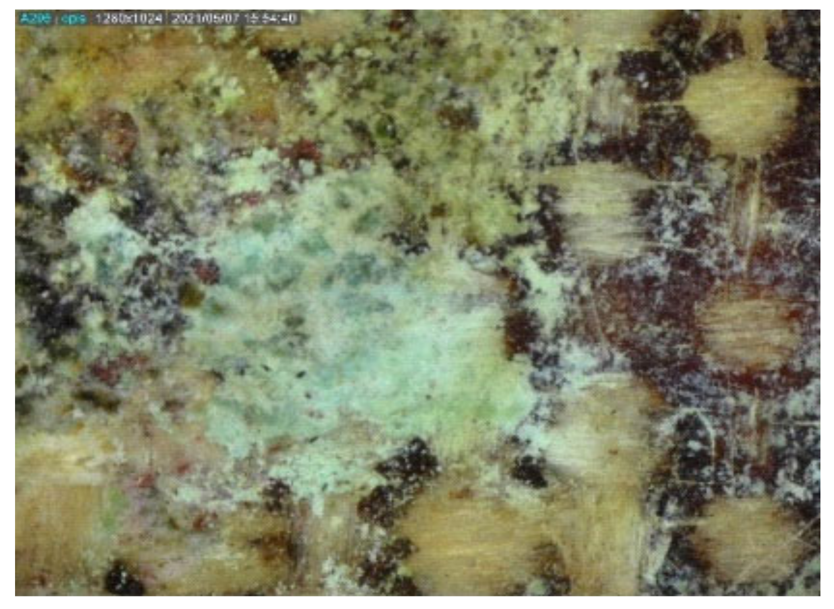
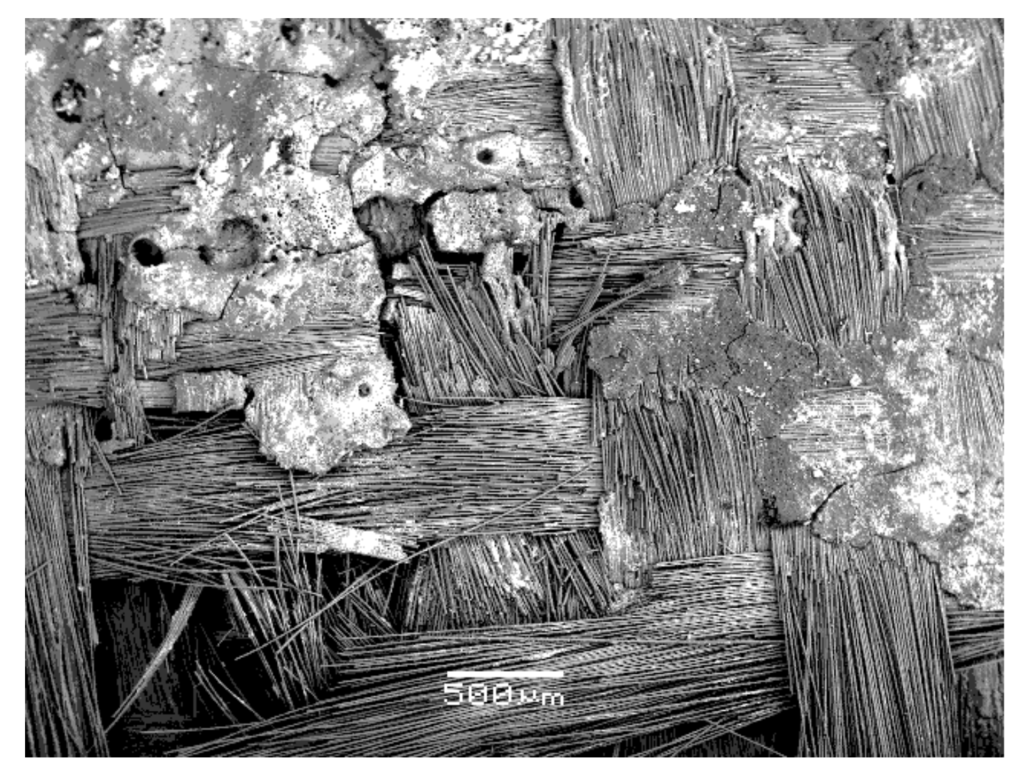
Flows of high discharge currents cause a large local temperature increase. Repeated flows of such currents in surge arresters lead to very strong degradation effects inside them. This applies in particular to elements made of laminate. During the examination of the damaged HV surge arresters that had been taken out of service, textolite elements were found, the degradation of which was very strong in some areas. A device operating at a 110 kV electrical substation suffered a serious failure after about 15 years of operation. The cause was most likely a loss of tightness and moisture ingress. Depending on the intensity and duration of the discharge currents, large differences were observed in the microstructure images and the degree of degradation of the textolite. The high temperature rise occurred only in certain, usually small, areas of the textolite elements inside the surge arresters. In these places, the epoxy resin, in particular, its top layer, had been strongly melted, charred and even burned out or chipped off (Figure 15, Figure 16 and Figure 17). The strongest degradation effects were found in the edge part of one of the textolite supports in the vicinity of the edge (Figure 15). Only the remnants of the strongly charred resin remained there. The textile support was unveiled and disturbances in the arrangement of the fibreglass bundles were created.
Figure 16 shows the burning and chipping off of large pieces of the epoxy resin from the sample surface and the exposure of the textile support. Some of the glass fibres were damaged as well. The fragments of resin remaining on the surface, apart from strong charring, showed characteristic cracking (Figure 17). More detailed observations with the use of various magnifications revealed the cracking and displacement of several glass fibres, and even damage and dislocation of their entire bundles in the textile support.
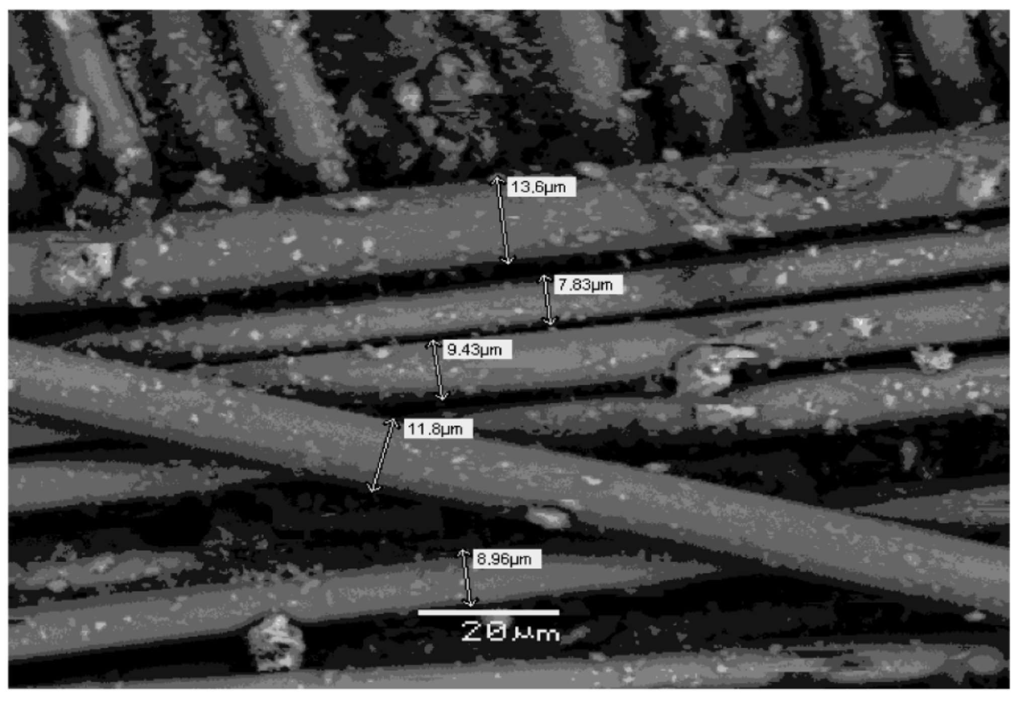
Strong damage or destruction of the epoxy resin top layer exposed the glass fibres of the support in many areas. Some of them were cracked and shifted. However, the visualisation of the support allowed for a more detailed inspection of the glass fibres and the assessment of their diameters (Figure 18). The measurements performed showed that the fibres had a diameter ranging from less than 8 µm to approximately 14 µm. The authors’ experience and literature data [31] show that in similar materials, the most common fibres are of a very similar diameter, i.e., a dozen or so micrometres (usually approx. 11 ÷ 17 µm).
The examined areas of the textolite elements from damaged surge arresters, which showed strong degradation, were distinguished by a large variety. This was especially true of the amount of the carbonised epoxy resin layer remaining on the surface. As a consequence, the EDS tests carried out at various points of a heavily degraded surface showed a very large variation in the results. The content of carbon and oxygen decreased further in favour of the elements coming from the glass fibres. The total weight share of the elements of textile support in the elemental composition of the upper layer of the laminate increased to the level of about 20%, excluding the oxygen part. The carbon content was at most about 60%, compared with the starting amount of almost 70%. The initial oxygen content, around 30%, dropped by over one-third. The amount of silicon, calcium and aluminium continued to increase. The values obtained from the individual EDS measurements were so different that even broad ranges for individual elements were not presented. Figure 19 shows an exemplary spectrum recorded for a sample of the material with a significant amount of charred and cracked epoxy resin on the surface.
3.7. A Greenish Deposit
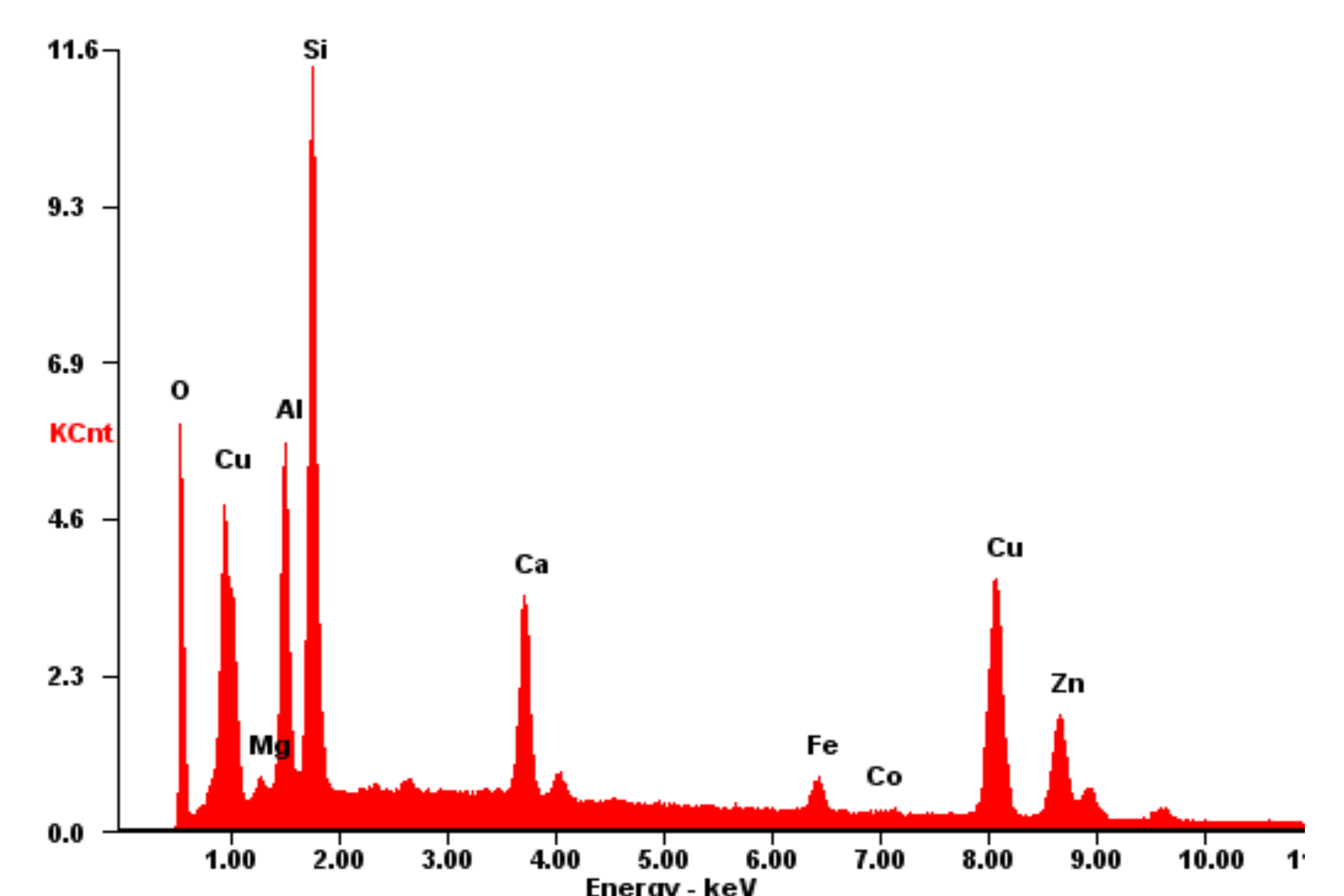
On one of the textolite elements, which was obtained from an unsealed and heavily damaged HV surge arrester, there were small areas with characteristic greenish sediment. The device operated at a 110 kV electrical substation and it suffered serious failure as a result of several successive strong surges. Two other arresters working on the remaining phases were also damaged. However, they were not obtained for research. Regardless of the very strong overvoltages, the device became unsealed and experienced moisture ingress. The sediment of greenish compounds indicates a chemical reaction that took place at a high temperature in the presence of H2O particles. Breakdown took place after about 10 years of operation. According to the authors’ experience, the presence of copper compounds in greenish sediment was to be expected [29,33]. The colour clearly indicated the presence of divalent copper (Cu2+ ions), especially as traces of exposure to high temperature and moisture inside the damaged arrester were found. The flow of large discharge (short-circuit) currents resulted in the emission of a large amount of heat. A small copper element, namely, the current connection inside the arrester, had been melted. As a consequence, metal fragments, most likely primarily in the form of copper (II) hydroxide/Cu(OH)2/or copper (II) carbonate hydroxide/CuCO3·Cu(OH)2/, were found on the textolite element.
Regardless of the copper compounds, the surface of the textolite element showed traces of high-temperature exposure and very severe degradation effects. Most of the epoxy resin melted and burned out, and the rest of it was completely charred. The microscopic images of places with greenish sediment were dominated by areas with exposed textile support. The deposition of copper compounds was not a thicker layer and was present both on the exposed bundles of the support fabric and on the carbonised resin. The fields of the greenish sediment were heterogeneous and had a small surface area, of the order of individual square millimetres at most (Figure 20).
Observations made with the SEM technique revealed cracks and characteristic cavities on the surface of the corrugated sediment layer. The thickness of the deposited layer was distinctly differentiated. Textile support was damaged in many places. Some of the fibres were cracked and moved. Even damage to the entire fibre bundles in the fabric was visible (Figure 21).
As in the case of heavily degraded surfaces, the EDS tests, which were carried out at different points in the occurrence of greenish sediment, gave results that differed significantly from one another. This was not surprising. The significant differences concerned the amount of the resin that was preserved on the surface, the exposed textile support fragments and the surface on which the sediment was located. At the same time, the sediment had different thicknesses and possibly also a non-uniform chemical composition. Figure 22 shows an exemplary EDS spectrum. It was obtained for an area where there was practically no epoxy resin, which melted and burned out, revealing the textile support.
4. Summary
The textolite material of the internal elements of HV surge arresters was tested. These elements were removed from various devices that were taken out of service and most often damaged, where discharge (short-circuit) currents of various intensities and durations had flown through them. The flows of these currents caused a local increase in temperature inside the surge arresters to varying degrees. This led to the degradation of the internal components of the devices. Apart from damage to the varistors, there were increasing degradation effects of the elements made of the laminate. Due to the much lower thermal resistance, this was especially true of the organic adhesive–epoxy resin.
All tested devices operated in overhead transformer substations in the central regions of the country, the same climate and very similar, low-pollution conditions (zone I) [32]. Practically there were no differences in environmental and contamination conditions between the workplaces of the devices. The main cause of malfunction or breakdown of the tested devices was unsealing and moisture ingress. It took place after a different period of operation and was not related to the working conditions.
During the study of the textolite elements, many areas were found where degradation effects occurred. However, depending on the intensity and duration of the discharge currents, and thus the temperature generated, there were significant differences in the microstructure patterns and degrees of the laminate degradation.
Moreover, due to the flow of short-circuit currents in certain parts of the devices, the degradation effects generally occurred only in certain areas of the textolite elements. Sometimes these were only small fragments of them. Moreover, it was found that the degradation effects often intensified near the edges of these elements.
Under the influence of high temperature, the epoxy resin, and especially its top layer, displayed gradual melting and charring, cracking and finally burning out. As a result, the fabric of the support of the laminate was exposed to an increased extent. However, with advanced degradation of the material, cracking and displacement of glass fibres were also observed. With strong degradation, whole bundles of the support fibres were damaged, i.e., cracked and even shifted. By convention, five stages of advancement of the effects of the laminate degradation were distinguished, from light to very strong.
The EDS analysis of the surface of the reference textolite element without any degradation effects showed a satisfactory agreement of the results. The surface area of the laminate was about 70% by weight of carbon (C) and about 30% by weight of oxygen (O), excluding the hydrogen content. In the case of degradation effects, elemental analysis of the surface layer also revealed the presence of glass-building elements, mainly silicon (Si), calcium (Ca) and aluminium (Al). As the degradation effects progressed, the content of carbon and oxygen on the laminate surface decreased, while the amount of silicon and metals increased. This is presented in Table 3.
On one of the textolite elements, which was obtained from a heavily damaged HV surge arrester, there were small areas containing a greenish sediment of copper compounds. Regardless of the deposit, the surface of the textolite element showed signs of exposure to high temperature and very severe degradation effects. The flow of high discharge currents in the unsealed device effected the release of large amounts of heat. As a result of this, a small copper element inside the limiter (current lead) underwent melting and a chemical reaction. In the presence of moisture, most likely copper (II) hydroxide/Cu(OH)2/ or copper (II) carbonate hydroxide/CuCO3·Cu(OH)2/ was formed, the sediment of which was found on the textolite element.
5. Conclusions
The thermal effects of partial discharges inside the surge arresters had a very strong influence on the condition of the textolite elements. Their degradation of varying intensity is often encountered when surge arresters are damaged. From the point of view of the proper functioning of the surge arrester, the carbonisation effect of an epoxy resin–laminate binder with dielectric properties should be considered particularly undesirable. Shielding, distance or centring elements of surge arresters must ensure appropriate electrical insulating properties. If the surge arrester becomes unsealed, the presence of moisture inside causes creeping discharges on its internal components. As a result, parts of the textolite surface are charred and burned. The charred resin forms conductive tracks, often at the surface of a stack of varistors, which bypass the varistors. The properties of the stack of varistors deteriorates significantly; the value of the current flowing through the varistors increases and the even harmonics content is increased. The operating parameters of the device, such as constant voltage and rated voltage, decrease [1,11,23]. This, therefore, leads to incorrect operation of the surge arrester.
- The increase in the severity of degradation processes and the enlargement of conductive paths in textolite elements may damage the device. Many years of operating experience and the authors’ practice demonstrate that this is caused by the properties of the textolite itself. Then, important elements of the power mains remain without proper protection against overvoltages.
- Everything points to the fact that the quite commonly used textolite materials show insufficient resistance to the effects of emergency operation of the surge arrester when it is wet, which is a consequence of unsealing of the cover (usually fixing device). The properties of textolite materials therefore reduce the durability and reliability of devices. Unfortunately, this fact is not taken into account by the manufacturers of surge arresters. In the opinion of the authors, countermeasures should be found to limit the degradation processes of textolite elements caused by the flow of discharge currents (creep discharges). The authors propose the use of additional protection of surge arresters in the form of covering its interior with a hydrophobic material of RTV type (room temperature vulcanised). This material is a silicone elastomer that is characterised by a low surface energy, which, in the presence of moisture, prevents the formation of a continuous wettable path on its surface and thus limits the development of the leakage current that is dangerous for the limiter. This coating is commonly used as additional protection for high voltage insulators. Its important component is alumina trihydrate (ATH), whose task is to lower the temperature caused by the occurrence of local surface discharges. In the opinion of the authors, such a solution would effectively limit the problems related to the degradation of textolite structures caused by the flow of large discharge currents, as well as small leakage currents.
Author Contributions
Conceptualisation: H.Ś., P.R. and K.W.; methodology: H.Ś., P.R., Z.R., K.W. and S.K.J.; validation: H.Ś., P.R., K.W. and S.K.J.; formal analysis: Z.R. and K.W.; investigation: H.Ś., P.R. and K.W.; data curation: Z.R. and K.W.; writing—original draft preparation: P.R. and K.W.; writing—review and editing: Z.R., K.W. and S.K.J.; supervision: Z.R. and S.K.J. All authors have read and agreed to the published version of the manuscript.
Funding
This research received no external funding.
Data Availability Statement
Not applicable.
Conflicts of Interest
The authors declare no conflict of interest.
References
- CIGRE Publication no. 544. MO Surge Arresters, Stress and Test Procedures. August 2013. Available online: https://e-cigre.org/publication/544-metal-oxide-mo-surge-arresters---stresses-and-test-procedures (accessed on 20 December 2021).
- Wang, B.S.; Wang, S.W.; Xiong, Y.; Wang, X.N.; Tang, L.; Zuo, Z.Q. The development of the UHV AC arresters. Eur. Trans. Electr. Power 2012, 22, 94–107. [Google Scholar] [CrossRef] [Green Version]
- Wang, D.; Chen, X.; Gao, L. Comparative experimental research on the LEMP protection effects of RF surge arresters with low-pass and band-pass frequency characteristics. In Proceedings of the 7th IEEE International Symposium on Microwave Antenna, Propagation, and EMC Technologies (MAPE), Xi’an, China, 24–27 October 2017; pp. 200–202. [Google Scholar] [CrossRef]
- Karbalaye Zadeh, M.; Abniki, H.; Shayegani Akmal, A.A. The Modeling of Metal-Oxide Surge Arrester Applied to Improve Surge Protection. In Proceedings of the 2nd International Conference on Power Electronics and Intelligent Transportation System (PEITS), Shenzhen, China, 19–20 December 2009. [Google Scholar] [CrossRef]
- Kobayashi, M. Development of gapless surge arresters and application of them to power system facilities. In Proceedings of the 33rd International Conference on Lightning Protection (ICLP), Estoril, Portugal, 25–30 September 2016. [Google Scholar] [CrossRef]
- Xia, Q.; Karady, G. An Efficient Surge Arrester Placement Strategy to Improve the Lightning Performance of Long Transmission Line. In Proceedings of the IEEE Power & Energy Society General Meeting (PESGM), Montreal, QC, Canada, 2–6 August 2020; pp. 1–5. [Google Scholar] [CrossRef]
- Bassi, W.; Janiszewski, J.M. Evaluation of currents and charges in low-voltage surge arresters due to lightning strikes. IEEE Trans. Power Deliv. 2003, 18, 90–94. [Google Scholar] [CrossRef]
- Hasse, P. Overvoltage Protection of Low-Voltage Systems, 2nd ed.; IET: Wrocław, Poland, 2000; ISBN 978-0852967812. [Google Scholar]
- Paul, D. Low-voltage power system surge overvoltage protection. IEEE Trans. Ind. Appl. 2001, 37, 223–229. [Google Scholar] [CrossRef]
- Paolone, M.; Nuci, C.A.; Petrache, E.; Rachidi, F. Mitigation of lightning-induced overvoltages in medium voltage distribution lines by means of periodical grounding of shielding wires and of surge arresters: Modeling and experimental validation. IEEE Trans. Power Deliv. 2004, 19, 423–431. [Google Scholar] [CrossRef]
- Chrzan, K.L. High-Voltage Surge Arresters; Dolnośląskie Wydawnictwo Edukacyjne: Wrocław, Poland, 2003. (In Polish) [Google Scholar]
- De Salles, C.; Picanco, A.F.; Martinez, M.L.B.; Oliveira, H.R.P.d.M. Determination of the Discharge Current on Distribution Network Surge Arresters. In Proceedings of the 2009 IEEE Bucharest PowerTech, Bucharest, Romania, 28 June–2 July 2009; pp. 1–7. [Google Scholar] [CrossRef]
- Zanetta, L.C. Evaluation of line surge arrester failure rate for multipulse lightning stresses. IEEE Trans. Power Deliv. 2003, 18, 796–801. [Google Scholar] [CrossRef]
- De Paulo Faria, I.; Martinez, M.L.B.; de Alencar Queiroz, A.A. Electrical performance evaluation of plasticized polyolefin formulation developed for manufacturing surge arresters housings. IEEE Trans. Dielectr. Electr. Insul. 2015, 22, 3429–3441. [Google Scholar] [CrossRef]
- Das, S.; Ghosh, R.; Dalai, S.; Chatterjee, B. Study on the effect of moisture ingression into metal oxide surge arrester using leakage current analysis. In Proceedings of the 3rd International Conference on Condition Assessment Techniques in Electrical Systems (CATCON), Rupnagar, India, 16–18 November 2017. [Google Scholar] [CrossRef]
- Bhurat, P.; Meera, K.S.; Vasudev, N. Failure of Distribution-Class Surge Arresters and Preventive Measures. In Proceedings of the International Conference on High Voltage Engineering and Technology (ICHVET), Hyderabad, India, 7–8 February 2019. [Google Scholar] [CrossRef]
- Das, A.K.; Dalai, S.; Chatterjee, B. A Novel Approach to Estimate the Quantity of Ingressed Moisture Content Inside Metal Oxide Surge Arrester Using Dielectric Modulus Technique. IEEE Trans. Dielectr. Electr. Insul. 2021, 28, 2178–2185. [Google Scholar] [CrossRef]
- Larsen, V.; Lien, K. In-Service Testing and Diagnosis of Gapless Metal Oxide Surge Arresters. In Proceedings of the Conference International Symposium on Lightning Protection, Paris, France, 10–13 November 2007; pp. 1–6. [Google Scholar]
- Lahti, K.; Kannus, K.; Nousiainen, K. Diagnostic Methods in Revealing Internal Moisture in Polymer Housed Metal Oxide Surge Arresters. In Proceedings of the IEEE Power Engineering Society Summer Meeting, Chicago, IL, USA, 21–25 July 2002. [Google Scholar] [CrossRef]
- Korycki, P. Fire and Explosion Hazard of Surge Arresters (Part 1), Elektro Info 10/2008. Available online: https://www.elektro.info.pl/artykul/instalacjeelektroenergetyczne/1477,zagrozenie-pozarem-i-eksplozja-beziskiernikowych-ogranicznikow-przepiec-czesc-1 (accessed on 20 December 2021).
- Gumede, M.; d’Almaine, G.F. Surge Arrester Faults and Their Causes at EThekwini Electricity. Int. J. Electr. Energy 2014, 2, 39–44. [Google Scholar] [CrossRef]
- He, J.; Lin, J.; Liu, W.; Wang, H.; Liao, Y.; Li, S. Structure-Dominated Failure of Surge Arresters by Successive Impulses. IEEE Trans. Power Deliv. 2017, 32, 1907–1914. [Google Scholar] [CrossRef]
- Chrzan, K.L. Influence of moisture and partial discharges on the degradation of high-voltage surge arresters. Eur. Trans. Electr. Power 2004, 14, 175–184. [Google Scholar] [CrossRef] [Green Version]
- Kim, J.; Park, C.; Jung, Y.; Song, I. An Investigation of Aging Characteristics of Polymer Housed Distribution Surge Arresters by Accelerated Aging Test. In Proceedings of the 2008 Annual Report Conference on Electrical Insulation Dielectric Phenomena, Québec, QC, Canada, 26–29 October 2008. [Google Scholar]
- Silva, D.A.; Costa, E.C.; Franco, J.L.; Abreu, S.R.; Jesus, R.C.; Antonionni, M.; Pissolato, J. Polymer Surge Arresters: Degradation Versus Electrical Performance. In Proceedings of the Electrical Power and Energy Conference, London, ON, Canada, 10–12 October 2012. [Google Scholar]
- Neto, E.T.W.; da Costa, E.G.; Ferreira, T.V.; Maia, M.J.A. Failure Analysis in ZnO Arresters Using Thermal Images. In Proceedings of the PES Transmission and Distribution Conference and Exposition, Caracas, Venezuela, 15–18 August 2006; pp. 15–18. [Google Scholar]
- Papliński, P.; Wańkowicz, J.; Ranachowski, P.; Ranachowski, Z. Microstructure and degree of degradation of ZnO varistors in surge arresters due to operation. Arch. Metall. Mater. 2018, 63, 1267–1273. [Google Scholar]
- Papliński, P.; Wańkowicz, J.; Śmietanka, H.; Ranachowski, P.; Ranachowski, Z.; Kúdela, S., Jr.; Aleksiejuk, M. Comparative studies on degradation of varistors subjected to operation in surge arresters and surge arrester counters. Arch. Metall. Mater. 2020, 65, 367–374. [Google Scholar]
- Papliński, P.; Ranachowski, P. Investigation of surfaces of internal elements of surge arresters. Przegląd Elektrotech. 2012, 88, 73–76. (In Polish) [Google Scholar]
- Plesa, I.; Notingher, P.V.; Schlögl, S.; Sumereder, C.; Muhr, M. Properties of Polymer Composites Used in High-Voltage Applications. Polymers 2016, 8, 173. [Google Scholar] [CrossRef] [PubMed]
- Standard PN-EN ISO2078:2011; Glass textiles—Threads—Markings. Polish Standard Committee: Warsaw, Poland, 2011.
- Standard PN-EN 50341-2-22:2016-04; Exposure of Overhead Insulation to Pollution and Selection of Insulators to Pollution Conditions. Polish Standard Committee: Warsaw, Poland, 2016.
- Wańkowicz, J.; Papliński, P. Application of Leakage Current Parameters for Technical Diagnostics of Surge Arresters. IEEE Trans. Dielectr. Electr. Insul. 2016, 23, 3458–3465. [Google Scholar]
Figure 1.
Textolite bushing support that came from an operated 110 kV surge arrester. Due to the lack of any degradation effects, the element was taken as a reference sample.
Figure 1.
Textolite bushing support that came from an operated 110 kV surge arrester. Due to the lack of any degradation effects, the element was taken as a reference sample.

Figure 2.
MO image of the surface of the reference sample textolite material (40 times magnification). The lighter weave of the support fabric is visible as fibreglass under a transparent resin layer.
Figure 2.
MO image of the surface of the reference sample textolite material (40 times magnification). The lighter weave of the support fabric is visible as fibreglass under a transparent resin layer.

Figure 3.
Typical EDS spectrum recorded for the surface of the reference sample textolite material. Only carbon and oxygen were present, which were derived from an organic epoxy resin. They represented 71.5% and 28.5% by weight, respectively.
Figure 3.
Typical EDS spectrum recorded for the surface of the reference sample textolite material. Only carbon and oxygen were present, which were derived from an organic epoxy resin. They represented 71.5% and 28.5% by weight, respectively.

Figure 4.
MO image of the textolite material’s surface with initial degradation effects (40 times magnification). There was a visible change in the colour of the material, indicating the process of carbonisation of the organic resin. Small fragments of the fibreglass textile support began to appear on the surface (marked in circles).

Figure 5.
Typical EDS spectrum registered for the textolite material with slightly marked degradation effects. There was already a low content of fibreglass support elements, namely, silicon (Si), calcium (Ca) and aluminium (Al), at the levels of 1.1%, 2.4% and 0.4%, respectively.
Figure 5.
Typical EDS spectrum registered for the textolite material with slightly marked degradation effects. There was already a low content of fibreglass support elements, namely, silicon (Si), calcium (Ca) and aluminium (Al), at the levels of 1.1%, 2.4% and 0.4%, respectively.

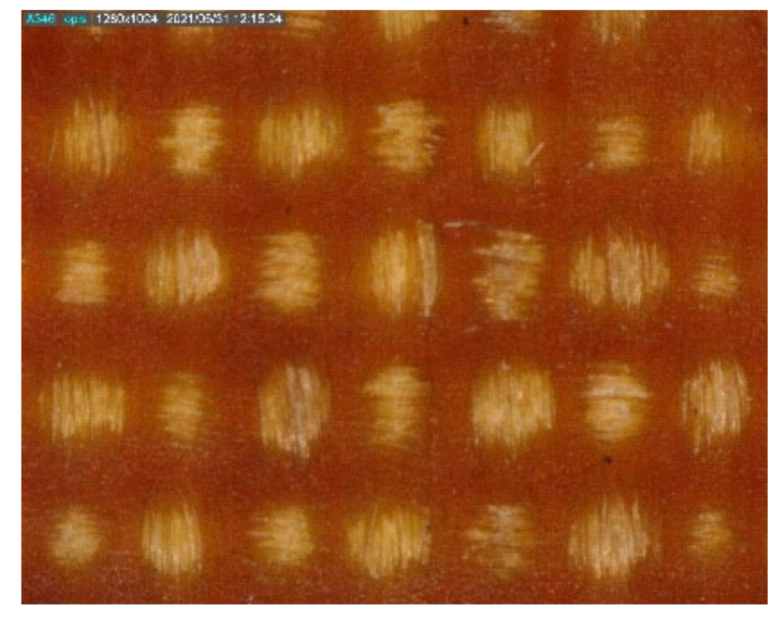
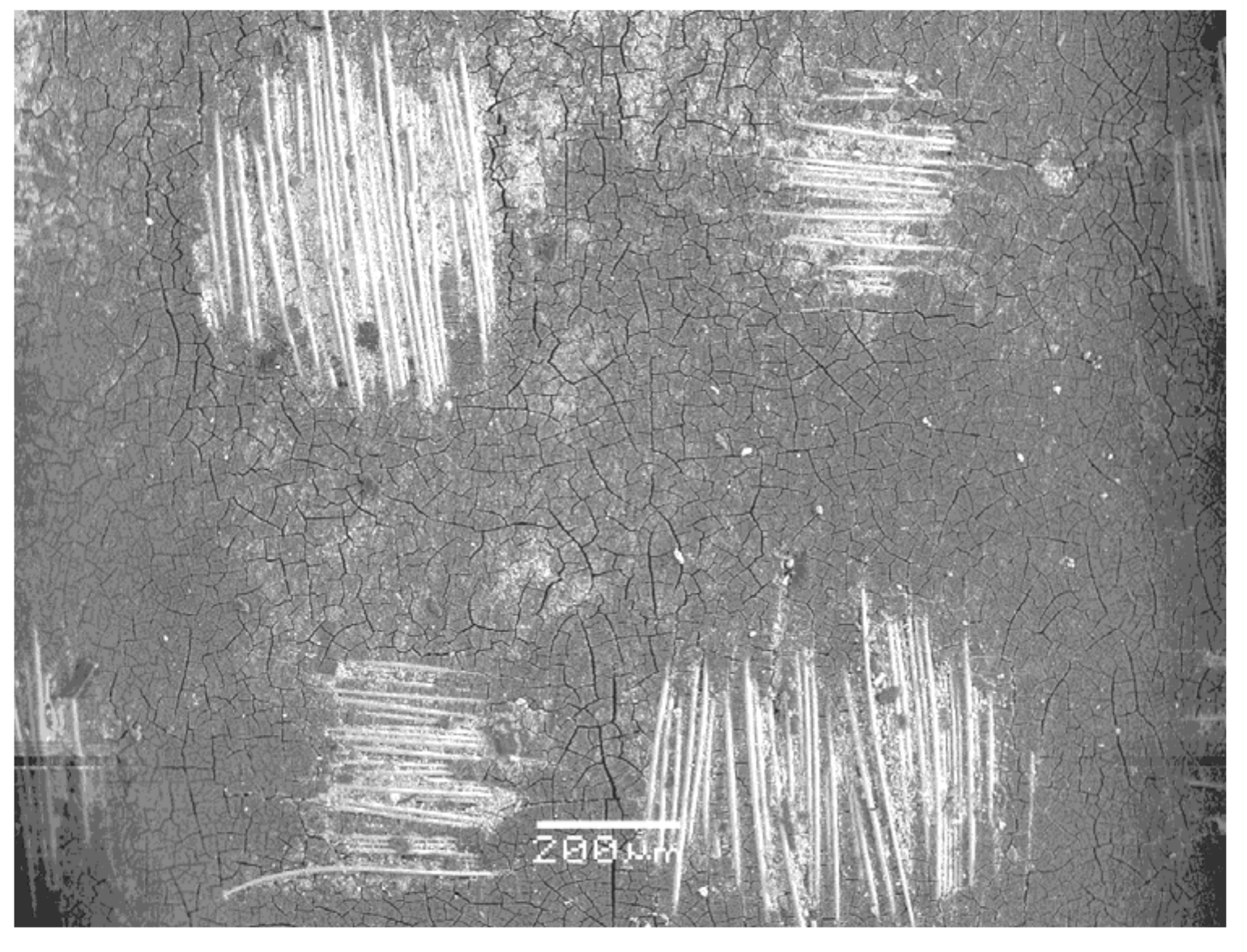
Figure 6.
MO image of the surface of the textolite material with clearly marked degradation effects (40 times magnification). Shiny bundles of fibres of the textile support are visible. They appeared on the surface of the material after the top layer of the resin had melted.
Figure 6.
MO image of the surface of the textolite material with clearly marked degradation effects (40 times magnification). Shiny bundles of fibres of the textile support are visible. They appeared on the surface of the material after the top layer of the resin had melted.

Figure 7.
SEM image of the textolite material surface with clearly marked degradation effects at a high magnification of 300 times. A network of small cracks in the resin surface is visible.
Figure 7.
SEM image of the textolite material surface with clearly marked degradation effects at a high magnification of 300 times. A network of small cracks in the resin surface is visible.

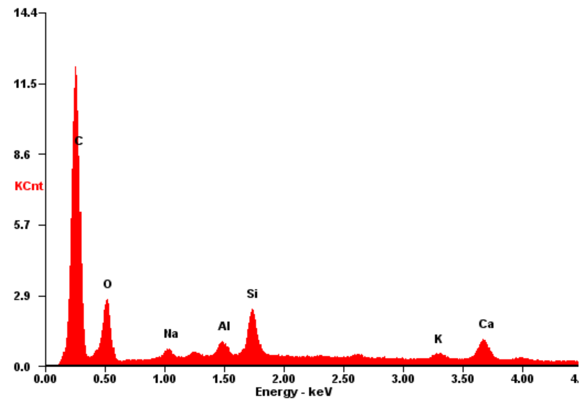
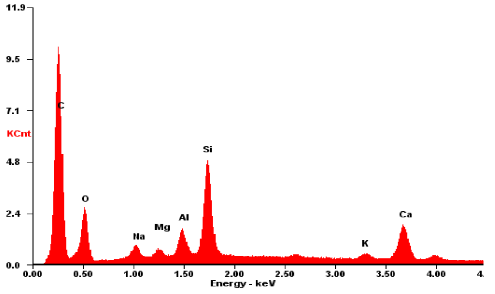
Figure 8.
The EDS spectrum recorded for the textolite material with evidently marked degradation effects. The contents of the elements present in fibreglass textile support (silicon, calcium, aluminium, potassium and sodium) are clearly visible.
Figure 8.
The EDS spectrum recorded for the textolite material with evidently marked degradation effects. The contents of the elements present in fibreglass textile support (silicon, calcium, aluminium, potassium and sodium) are clearly visible.

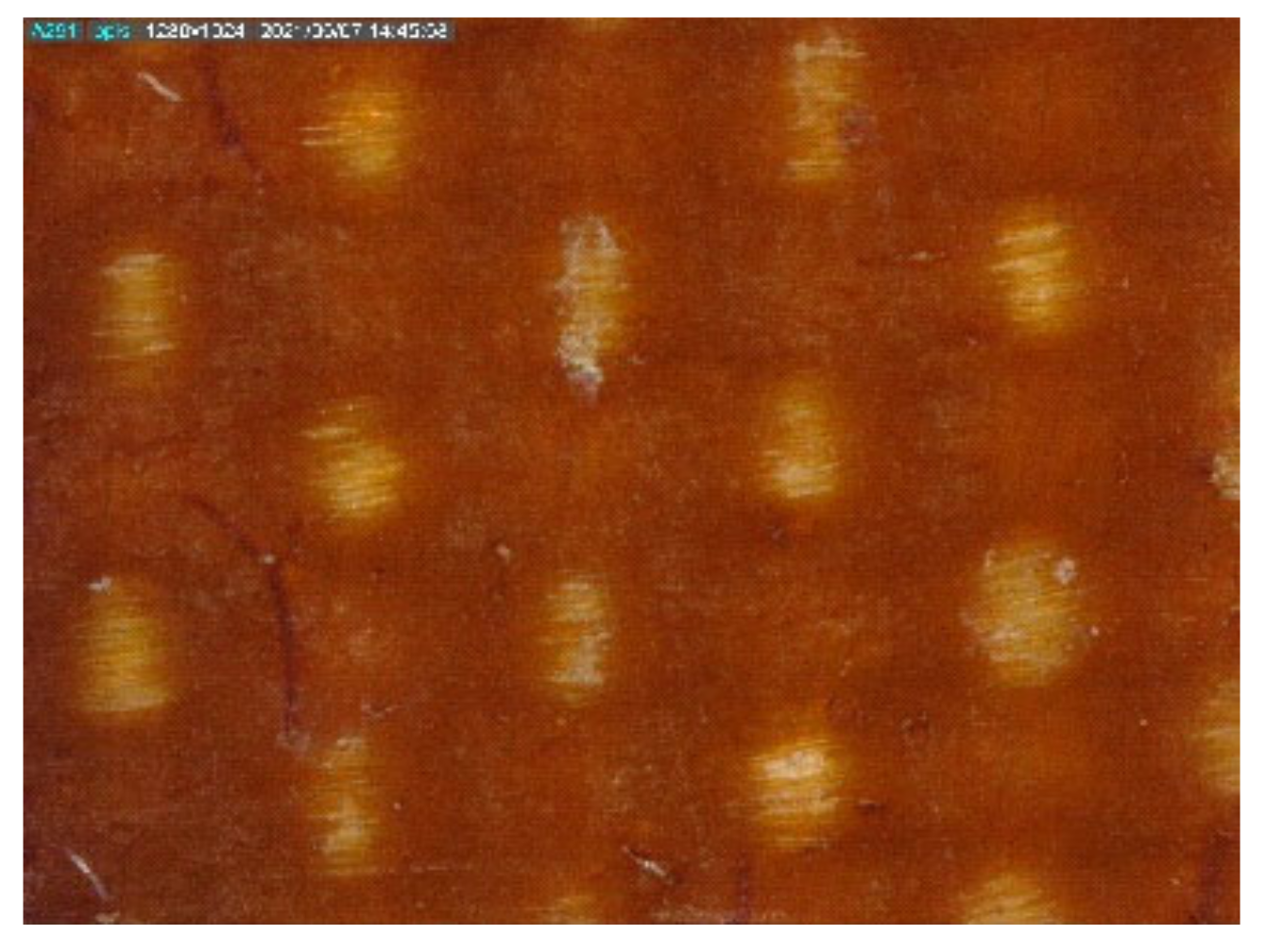
Figure 9.
MO image of the surface of the textolite material with advanced degradation effects (40 times magnification). Significant carbonisation of the organic binder of the sample material occurred. Numerous bright fibre bundles of the textile support are visible. After the top layer of the resin had melted, the fibre bundles were found on the laminate surface.

Figure 10.
SEM image of the textolite material surface with visible degradation effects (75 times magnification). In addition to the light bundles of fibres of the textile support, there was clear cracking of the top layer of resin.
Figure 10.
SEM image of the textolite material surface with visible degradation effects (75 times magnification). In addition to the light bundles of fibres of the textile support, there was clear cracking of the top layer of resin.

Figure 11.
A typical EDS spectrum registered for the textolite material with advanced degradation effects. On the surface, there is a significant share of the elements present in the fibreglass support, namely, silicon and metals.
Figure 11.
A typical EDS spectrum registered for the textolite material with advanced degradation effects. On the surface, there is a significant share of the elements present in the fibreglass support, namely, silicon and metals.

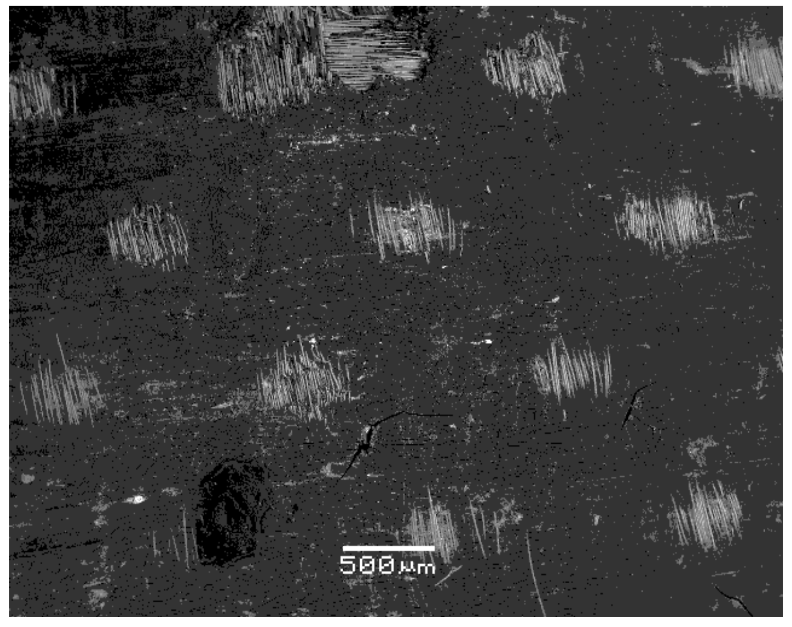
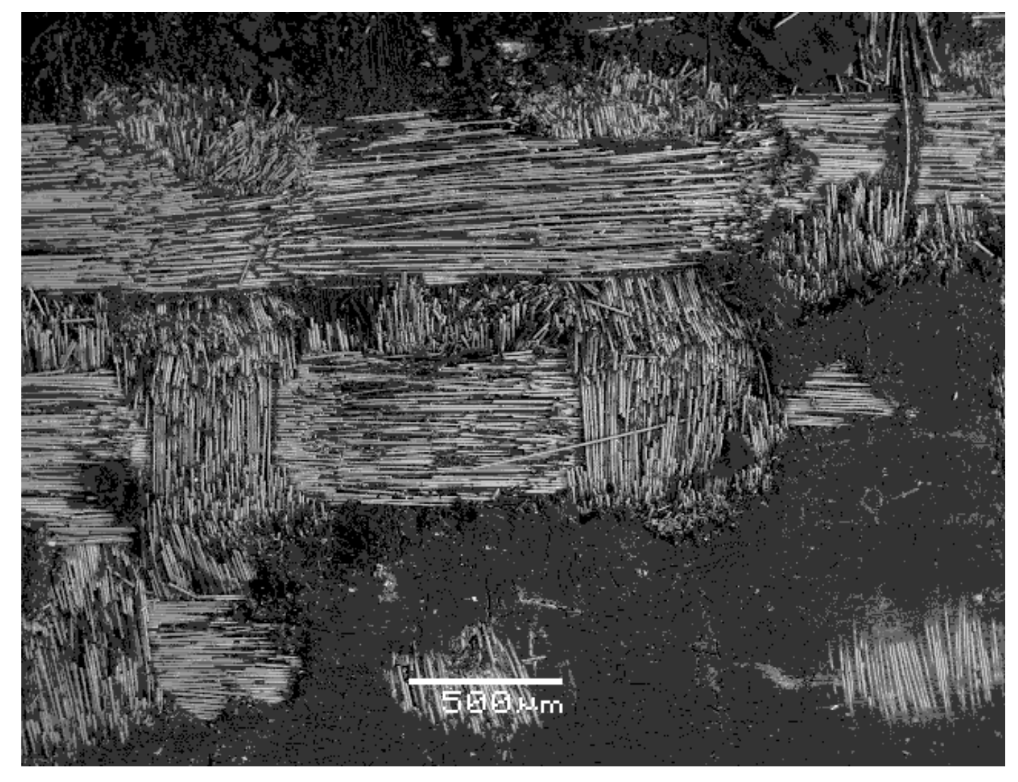
Figure 12.
SEM image of the surface of the textolite material with strong degradation effects (30 times magnification). There is a large amount of charring and melting of the resin visible in the top layer of the material and numerous bundles of bright fibres of the textile support on the surface. There were also single large cracks in the resin.

Figure 13.
MO image of the surface of the textolite material with intensified degradation effects (40 times magnification). The edge part of the textolite element is visible, in which a strong charring and burning out of a fragment of the top layer of the resin took place. On the left side, at the edge, the exposed textile support is visible.

Figure 14.
Exemplary EDS spectrum recorded for a textolite material with enhanced degradation effects. The contribution of the elements present in the fibreglass support, especially silicon, calcium and aluminium, was important. Oxygen was present in both the organic and the amorphous phases.
Figure 14.
Exemplary EDS spectrum recorded for a textolite material with enhanced degradation effects. The contribution of the elements present in the fibreglass support, especially silicon, calcium and aluminium, was important. Oxygen was present in both the organic and the amorphous phases.

Figure 15.
MO image of the marginal part surface of the textolite support, which was heavily degraded (40 times magnification). In the immediate vicinity of the edge, the resin had been almost completely burned out; the exposed textile support is visible.
Figure 15.
MO image of the marginal part surface of the textolite support, which was heavily degraded (40 times magnification). In the immediate vicinity of the edge, the resin had been almost completely burned out; the exposed textile support is visible.

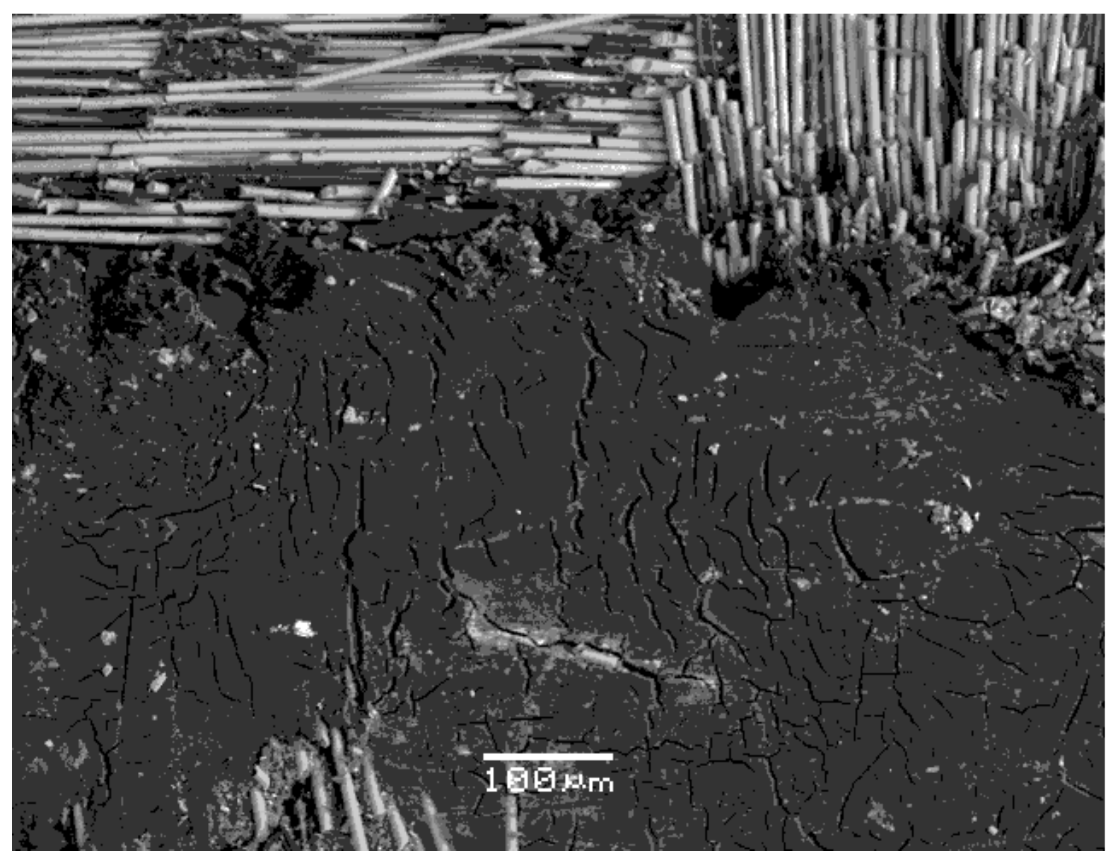
Figure 16.
SEM image of the surface of the textolite material with very strong degradation effects (40 times magnification). The resin on the top layer of the material had been largely melted, charred and burned out. In the visible textile support, the fibre bundles were damaged and moved.
Figure 16.
SEM image of the surface of the textolite material with very strong degradation effects (40 times magnification). The resin on the top layer of the material had been largely melted, charred and burned out. In the visible textile support, the fibre bundles were damaged and moved.

Figure 17.
SEM image of the textolite surface with very strong degradation effects (150 times magnification). Strong cracking of the carbonised resin and damage to the glass fibres in the textile support is visible.
Figure 17.
SEM image of the textolite surface with very strong degradation effects (150 times magnification). Strong cracking of the carbonised resin and damage to the glass fibres in the textile support is visible.

Figure 18.
SEM image of the surface of very badly damaged textolite material (magnified 900 times). Exposed textile support glass fibres are visible, and on their surfaces are the remains after the destruction of the organic phase.
Figure 18.
SEM image of the surface of very badly damaged textolite material (magnified 900 times). Exposed textile support glass fibres are visible, and on their surfaces are the remains after the destruction of the organic phase.

Figure 19.
Exemplary EDS spectrum recorded for a textolite material with very strong degradation effects. The results for the sample with a significant amount of highly charred and cracked epoxy resin on the surface. There was a large share of elements present in the glass support, i.e., silicon and metals. Oxygen was present in both components of the laminate.

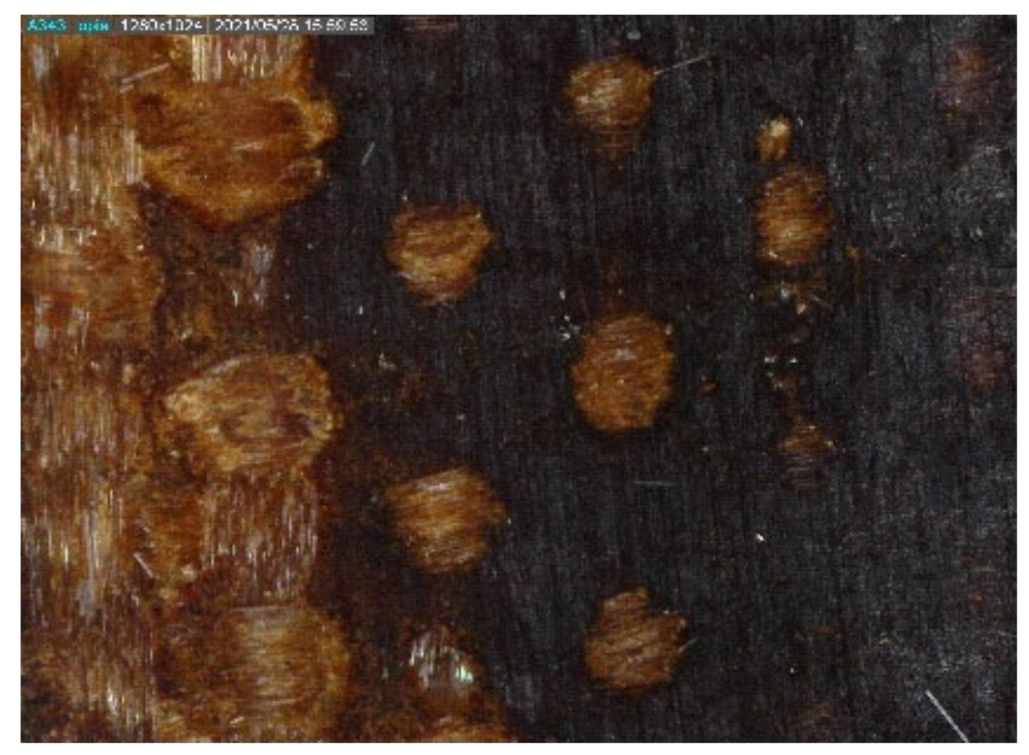
Figure 20.
MO image of the surface of a textolite material with a greenish deposit of copper compounds and very strong degradation effects (magnified 40 times). Strong charring of resin residues on the surface of the sample material is visible.
Figure 20.
MO image of the surface of a textolite material with a greenish deposit of copper compounds and very strong degradation effects (magnified 40 times). Strong charring of resin residues on the surface of the sample material is visible.

Figure 21.
SEM image of the surface of the textolite material with a copper compounds sediment and very strong degradation effects (magnified 35 times). The resin on the top layer of the material was almost completely charred and burned out. Damage to the textile support is visible. There were cracks and characteristic cavities in the sediment layer.

Figure 22.
Exemplary EDS spectrum registered for a fragment of a textolite material with sediment made of copper compounds and very strong degradation effects. Copper was present from the sediment layer, along with elements from the glass support.
Figure 22.
Exemplary EDS spectrum registered for a fragment of a textolite material with sediment made of copper compounds and very strong degradation effects. Copper was present from the sediment layer, along with elements from the glass support.


Table 1.
Exemplary results of EDS tests on the surface of the textolite sample with slight degradation effects. Weight (Wt) and atomic (At) composition of the top layer of the laminate are presented as percentages.
Table 1.
Exemplary results of EDS tests on the surface of the textolite sample with slight degradation effects. Weight (Wt) and atomic (At) composition of the top layer of the laminate are presented as percentages.
| Element | Wt % | At % |
|---|---|---|
| C | 67.05 | 74.86 |
| O | 27.27 | 22.86 |
| Al | 00.88 | 00.43 |
| Si | 01.62 | 00.78 |
| K | 00.78 | 00.27 |
| Ca | 02.40 | 00.80 |
Table 2.
Exemplary results of EDS tests on a textolite material with enhanced degradation effects. The weight (Wt) and atomic (At) composition of the laminate top layer in per cent are shown.
Table 2.
Exemplary results of EDS tests on a textolite material with enhanced degradation effects. The weight (Wt) and atomic (At) composition of the laminate top layer in per cent are shown.
| Element | Wt % | At % |
|---|---|---|
| C | 58.27 | 70.49 |
| O | 21.91 | 19.89 |
| Na | 01.75 | 01.11 |
| Mg | 00.83 | 00.49 |
| Al | 02.69 | 01.45 |
| Si | 08.35 | 04.32 |
| K | 00.73 | 00.27 |
| Ca | 05.47 | 01.98 |
Table 3.
Changes in the elemental composition of the top layer of the textolite material in per cent by weight for the subsequent stages of progressive material degradation. Data were based on EDS X-ray microanalysis. Carbon and oxygen were part of the epoxy resin (organic binder). Silicon, calcium and aluminium, as well as some oxygen, were components of the glass fibres of the fabric, i.e., the support of the laminate. In the case of very strong degradation of the material, there was a large scatter of the results and it was difficult to provide reliable values.
| Weight Content (%) | Reference State (%) | Light Degradation | Clear Degradation | Advanced Degradation | Strong Degradation |
|---|---|---|---|---|---|
| Carbon | 66.0–71.5 | 67.0–69.4 | 64.0–65.7 | 60.7–62.7 | 56.7–60.5 |
| Oxygen | 28.5–31.0 | 27.1–28.3 | 26.3–27.1 | 22.8–25.0 | 21.9–23.6 |
| Silicon | – | >1.0 | ca. 2.5 | 3.9–5.4 | 6.7–8.4 |
| Calcium | – | 1.5–2.4 | 2.0–3.0 | 3.3–4.2 | 4.6–8.0 |
| Aluminium | – | <1.0 | >1.0 | 1.4–1.8 | 2.3–2.8 |
Publisher’s Note: MDPI stays neutral with regard to jurisdictional claims in published maps and institutional affiliations. |
© 2022 by the authors. Licensee MDPI, Basel, Switzerland. This article is an open access article distributed under the terms and conditions of the Creative Commons Attribution (CC BY) license (https://creativecommons.org/licenses/by/4.0/).
Share and Cite
MDPI and ACS Style
Śmietanka, H.; Ranachowski, P.; Ranachowski, Z.; Wieczorek, K.; Kudela, S., Jr. Effects of Degradation in Textolite Elements of Damaged Surge Arresters. Energies 2022, 15, 3643. https://0-doi-org.brum.beds.ac.uk/10.3390/en15103643
AMA Style
Śmietanka H, Ranachowski P, Ranachowski Z, Wieczorek K, Kudela S Jr. Effects of Degradation in Textolite Elements of Damaged Surge Arresters. Energies. 2022; 15(10):3643. https://0-doi-org.brum.beds.ac.uk/10.3390/en15103643
Chicago/Turabian StyleŚmietanka, Hubert, Przemysław Ranachowski, Zbigniew Ranachowski, Krzysztof Wieczorek, and Stanislav Kudela, Jr. 2022. "Effects of Degradation in Textolite Elements of Damaged Surge Arresters" Energies 15, no. 10: 3643. https://0-doi-org.brum.beds.ac.uk/10.3390/en15103643
Note that from the first issue of 2016, this journal uses article numbers instead of page numbers. See further details here.