1. Introduction
For several years, wind power plants have shown a trend toward higher power classes [
1,
2]. To enable technically feasible solutions for Megawatt-scale systems, the generator needs to be designed for a low rated rotor speed and a high rated input torque. However, this design approach drastically increases the mass and the volume of the generator [
3]. Because a larger generator also leads to higher investment costs, lightweight concepts such as those proposed in [
4,
5,
6] have been investigated. Besides these conventional lightweight concepts, the use of superconductors is very promising, as shown in [
7], because superconducting generators offer a much better power to mass ratio. To exploit the full potential of the superconductor, the generator should be fully superconducting [
8], i.e., both the DC and the AC winding should be designed and manufactured with superconducting materials. However, the AC current leads to AC losses in the superconductor, which have to be handled by the cryogenic cooling system, reducing the overall efficiency of the system. Because each loss contribution at cryogenic temperatures has to be extracted through a proportionally larger power consumption of the cooling system, the generator has to be optimised for low AC losses. One of the key parameters to achieve low AC losses is the number of pole pairs, as described in
Section 2.
The influence of the number of pole pairs on the cost of a generator is demonstrated in [
9]. Additionally, the number of pole pairs is also coupled to the output voltage and the electric frequency of the generator, which in turn influence the design of the power electronic converter (PEC). Its weight, size, cost and efficiency have an impact on the overall system as well. However, the consequences for the design of a PEC for fully superconducting generators with minimised AC losses have not yet been discussed in literature.
This study investigates the interdependencies between the design of a fully superconducting synchronous generator (FSSG) and its PEC in the context of the project SupraGenSys. First, the influence of the number of pole pairs on the output voltage of the generator will be investigated analytically in
Section 2. An exemplary design of a fully superconducting generator is then presented in
Section 3. This design is investigated regarding the influence of the number of pole pairs and of the pole pitch on the overall design feasibility in
Section 4. The influence of these design parameters on the output voltage of the generator is provided for each studied parameter. Based on the feasible generator design options,
Section 5 highlights available choices for the rectifier–machine interface.
Section 6 then investigates possible design concepts of PECs and their influence on the overall FSSG system design.
This study is not intended to provide a complete design method for FSSGs but to enable an understanding of the challenges and available options for the interface between an FSSG and its PEC.
2. Dependencies and System Design Conflicts
One of the key aspects regarding the design of superconducting generators is the minimisation of the AC losses occurring inside their superconducting AC winding. Together with the conductive heat flow from the environment through the electrical connections and into the superconducting winding they form the major part of the heat that has to be extracted by the cryogenic cooling system. The higher these losses are, the larger (more powerful) the cooling system has to be designed and the higher is its power consumption, lowering the overall efficiency of the system. A rough estimation for the AC losses in High Temperature Superconductor (HTS) tapes
was introduced in ([
10], p. 21) and [
11] and can be expressed with
where
is the tangential flux density that the HTS tape is exposed to,
is the frequency of the AC current of the generator,
d is the width of the HTS tape,
is the effective length of the HTS tape and
is the critical current of the HTS tape. With a lower operating temperature, the critical current of the HTS tape increases, but at the same time the electrical power required for the cryogenic cooling system increases as well. Therefore, an operating temperature of 65 K for the armature winding is selected as a tradeoff between a high critical current and a low cryogenic cooling power. The field winding is only driven by DC current; hence, a lower operating temperature of 30 K becomes feasible.
This equation was developed in ([
10], p. 21) as an estimate of the AC losses and is only valid for coil currents close to the critical current. This condition is observed for all investigations presented in this study.
In other applications, e.g., distribution grids, superconductors are often used to increase the current handling capability compared to conventional copper or aluminium wires in limited spaces. Based on these applications, it might therefore be expected to use high coil currents in FSSGs as well. However, one possibility to minimise AC losses in HTS tapes that follows (
1) is the reduction in the width of the tape
d. Because HTS tapes greatly impact the overall investment costs for a FSSG, a tape width of
d = 2 mm was selected, providing a critical current of
Ic = 52 A. This tape width is currently the most narrow one available.
A second approach to minimise AC losses is the electric frequency
, which—for a synchronous generator—is directly coupled to the rotor speed
n through the number of pole pairs
p:
Combining (
1) and (
2) to (
3) clearly shows the dependency of the HTS tape AC losses
on the number of pole pairs
p:
This equation also shows the dependency of the AC losses on the tangential flux density
and the effective HTS tape length
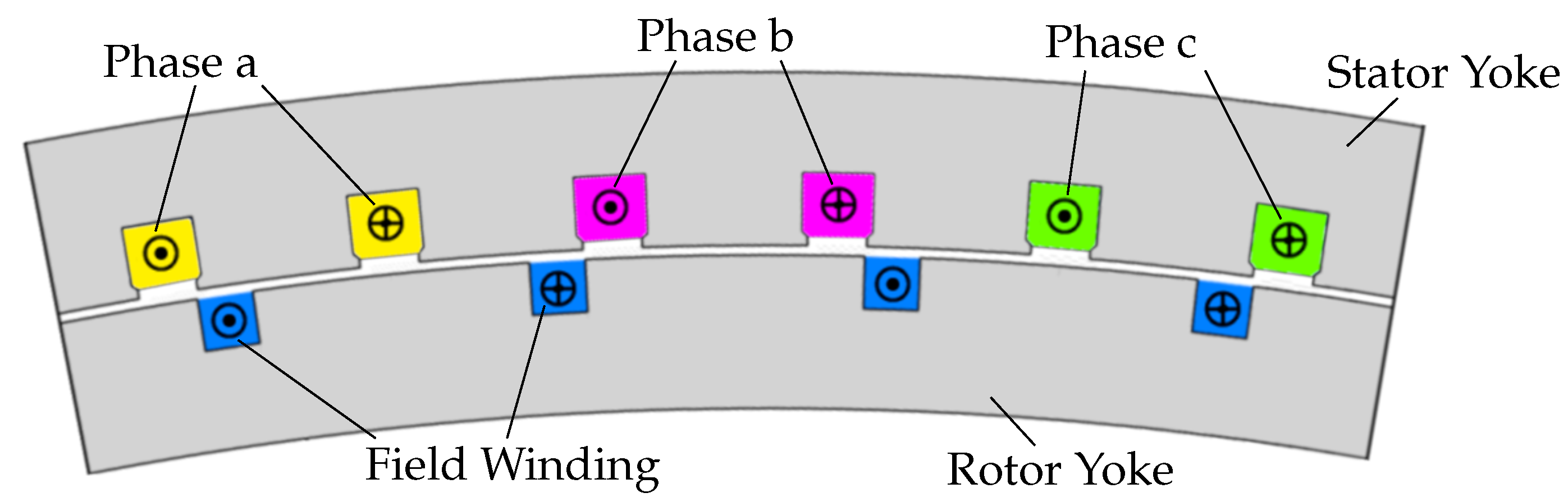
, which in turn are coupled to the power density of the generator. Apart from the AC losses, the number of coils of the armature winding is coupled to the number of pole pairs as well. Each coil has two coil sides which need to be placed in slots. A common description for this physical placement is the number of slots per pole and per phase
which is coupled to the chosen winding scheme.
is the number of slots and
m is the number of phases. The armature coils per phase can be connected in series, in parallel or in a series–parallel combination, as long as all coils are used. For a fixed number of turns per coil, a series connection increases the voltage between the phase contacts whereas a parallel connection increases the phase current. These properties have to be handled by the PEC and need to be known before it is designed. They can be identified through the apparent power
of the generator according to
where
and
are the RMS phase current and the RMS phase voltage at the terminals of the generator, respectively, assuming a star connection of
phases. The internal connection of the coils inside the armature winding can be described through the number of parallel branches per phase
a. Through this number, the phase current for the PEC is given as
Expressing the apparent power
of the generator in (
5) through the real power
and the power factor
allows the calculation of the phase voltage according to
Equation (7) demonstrates the strong dependency of the phase voltage U1 on the
number of parallel branches a, because . For a power rating in the MW range and a
coil current of Icoil ≈ Ic = 52 A, large phase voltages U1 have to be expected even without a
series connection of the coils inside the armature winding. Although a suitable PEC could
theoretically be designed, practical issues such as component properties and device costs
usually aim for a more balanced distribution of voltage and current load for a PEC, which
in this case requires the parallel connection of the FSSG coils.
However, the possibility to connect coils in parallel is limited by the number of pole
pairs. By selecting q = 1 in (4) and choosing a single-layer winding, the number of parallel
branches a cannot to be higher then the number of pole pairs p, which in this case defines
the number of connectable coils per phase. Combined with (3), this behaviour presents a
conflict between the design of the PEC and the minimisation of AC losses.
After presenting an exemplary FSSG design in
Section 3, the following sections will
therefore explore design options both for the FSSG and the PEC to find suitable compromises
between these design goals.
4. Parameter Studies for an FSSG
As described in
Section 2, the number of pole pairs
p influences both the AC losses inside the HTS tape and the phase voltage at the terminals of the generator. To find a feasible range for the number of pole pairs, a parameter study was performed (
Section 4.1), investigating its impact on the design of the FSSG.
For this investigation, a generator design based on the constraints and design rules of
Section 3 is varied. These variants are each parameterised analytically and then modelled and simulated in FEMAG-DC. The simulation is used to validate the targeted output torque and to acquire the phase inductance, power factor, output voltages and the flux density distribution for the HTS coils. These results, especially the flux density, are then used to estimate the AC losses according to (
1).
Beside the number of pole pairs, the power density is a major design parameter with an impact to the AC losses and the PEC. Due to the fixed number of turns per coil and coil current, it is mainly defined by the pole pitch. Hence, a second parameter study investigates the effects of varying pole pitches (
Section 4.2).
All parameter studies consider the target values and design principles described in
Section 3. The study regarding the influence of varying pole pair numbers assumed a fixed pole pitch of 350 mm whereas the following pole pitch investigation assumed a fixed number of pole pairs of
p = 35.
4.1. Parameter Study 1: Variation of the Number of Pole Pairs
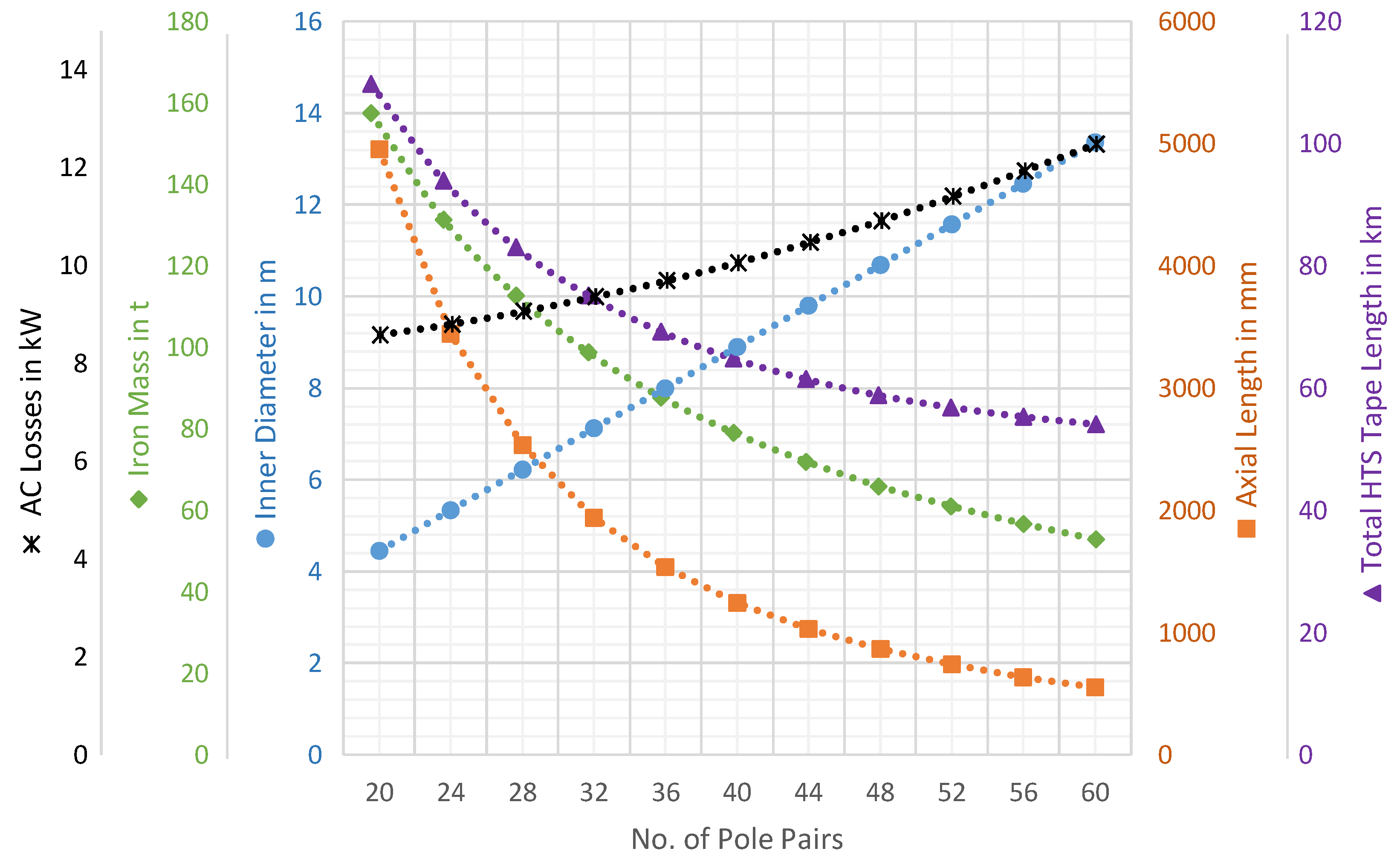
Figure 2 shows a linear, positively coupled relation between the inner diameter of the stator and the number of pole pairs, whereas the axial stack length of the iron sheets decreases with higher number of pole pairs. These changes in turn influence the iron mass and the required HTS tape length.
Even though a lower number of pole pairs reduces the diameter of the generator, the corresponding increase in its axial length has a significant impact on its mass and on the required amount of HTS tape. In contrast, a design with a higher number of pole pairs will result in a shorter, more lightweight generator with much lower demand of HTS tape length. On the other hand, the AC losses are increasing with the number of pole pairs, which increases the energy demand of the cryogenic cooling system significantly.
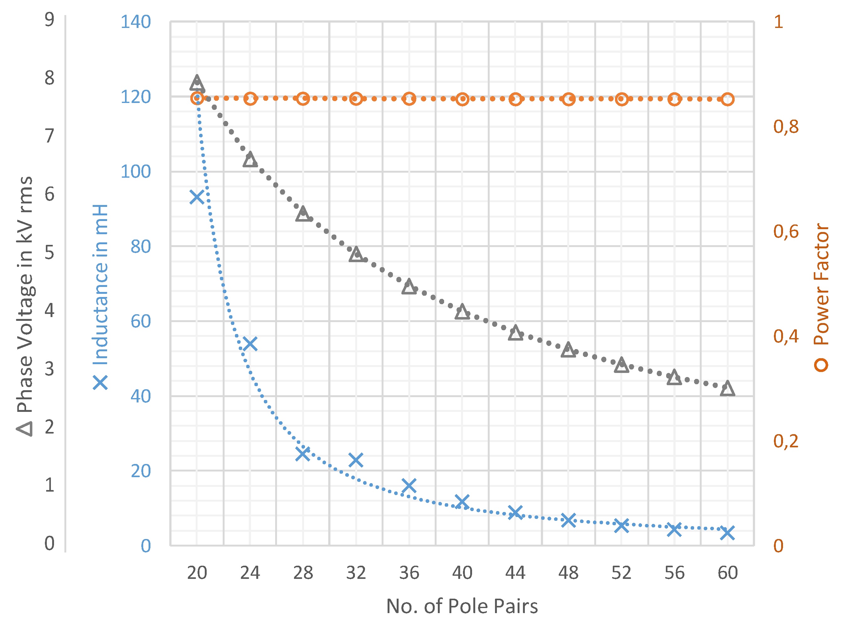
Figure 3 shows the dependency of the phase voltage, the phase inductance and the power factor with a changing number of pole pairs. The number of pole pairs has no impact on the power factor, because the winding and thus the field distribution are not affected. A higher number of pole pairs enables a higher number of parallel branches and, therefore, a lower output voltage according to (
7) and (
8). The number of parallel branches together with the change of the HTS tape length results in the shown behaviour of the inductance, which is also the reason for the small differences between the interpolated curve and the calculated values of the inductances.
The results of this parameter study can be summarised to the basic design rule: A smaller number of pole pairs has a positive impact on the AC losses in an FSSG but in turn requires an increase in the total iron core mass and HTS tape length. Therefore, a decreasing number of pole pairs results in a higher material cost for the generator.
4.2. Parameter Study 2: Variation of the Pole Pitch
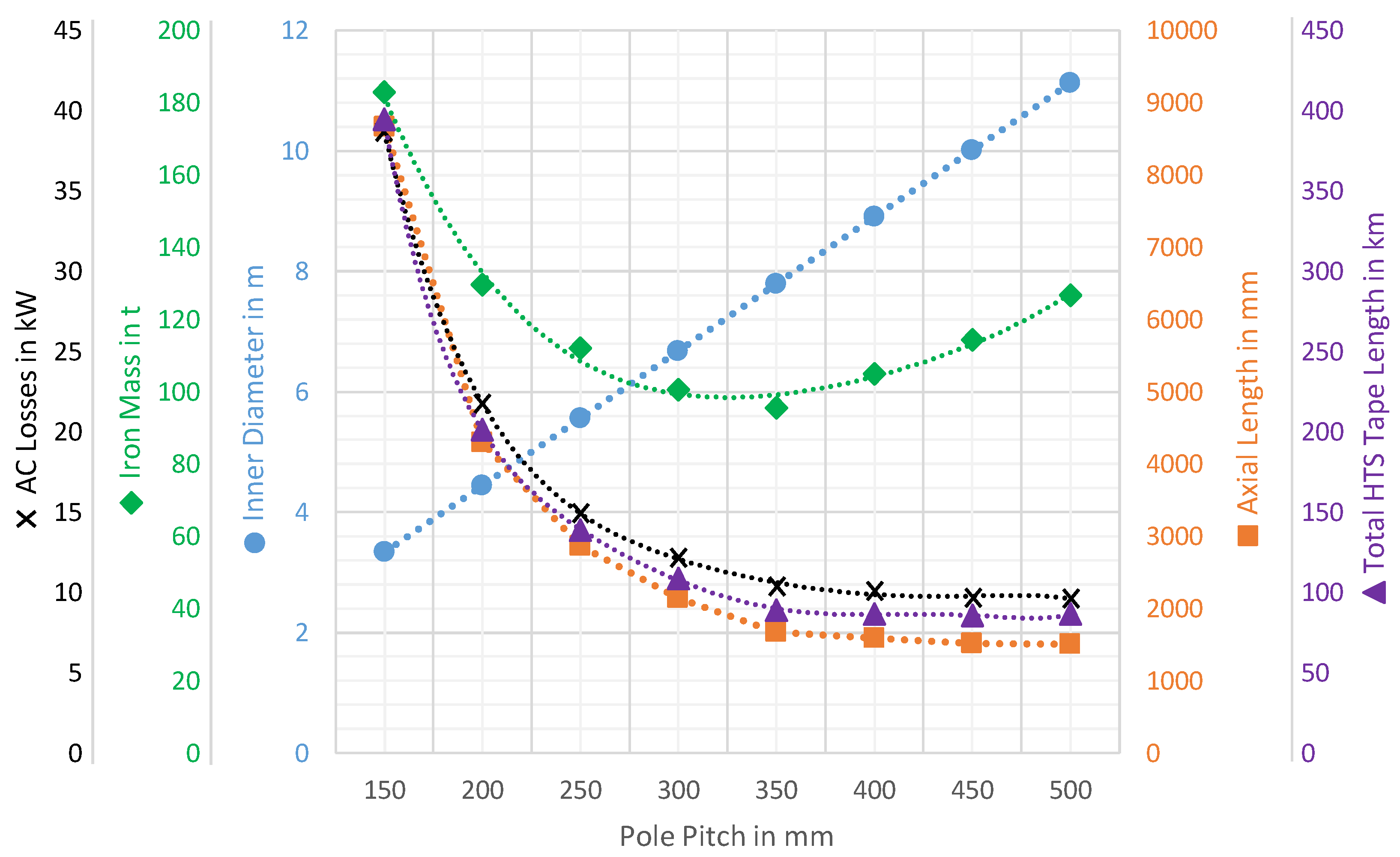
The previous investigation showed that the axial length of the generator greatly influences its mass, and, consecutively, its material cost. It was therefore interesting to investigate design methods that could counter this mass increase, e.g., by choosing a higher bore diameter, which in turn changes the pole pitch. A larger pole pitch will have a negative impact on the iron losses but can enable more desirable machine lengths to reduce the mass and the HTS tape length.
Figure 4 shows the properties of the generator for varying pole pitches. Because the number of pole pairs is fixed for this part of the parameter study, a reduced pole pitch results in a smaller diameter and a larger active length. Hence, a smaller pole pitch enables lower total iron losses, but the larger active length of such a machine requires more HTS tape and increases the AC losses inside the superconductor.
The generator output voltage, the phase inductance and the power factor are shown in
Figure 5. For larger pole pitches, neither the iron mass, the output voltage, the power factor nor the phase inductance decrease monotonously but exhibit extrema between pole pitches of 350 to 400 mm. The output voltage is inversely coupled to the power factor as described in (
7), which in turn is influenced by the phase inductance that is affected by the saturation of the iron sheets.
4.3. Summary of Parameter Studies
Overall, the study regarding the influence of the pole pitch suggests an optimal value between 300 and 400 mm for the investigated FSSG concept. However, choosing the number of pole pairs is a tradeoff between CAPEX, generator mass, size and efficiency.
A smaller number of pole pair numbers reduces the total losses of the FSSG but results in heavier, longer machine designs that require more HTS tape. At the same time, lower pole pairs create higher generator output voltages of several kV with relatively low phase currents of 52 A. Within the framework of the SupraGenSys project, it was found that the decision for a specific number of pole pairs cannot be made without investigating the power rectifier as well. Therefore, the FSSG design has to go hand in hand with the design of the PEC.
5. Design Options for the Rectifier–Machine Interface
As described in
Section 2, the RMS phase voltage
U1 of a synchronous generator can be calculated according to (
7). Depending on the topology of the PEC, either the peak phase voltage or the peak phase-to-phase voltage define the maximum voltage that power semiconductors inside a power rectifier are exposed to. Ignoring overvoltage events and observing (
8) for the investigated FSSG concept, these peak values calculate according to (
9) and (10), respectively.
By applying a sweep of the number of pole pairs
p to (10) with an assumed power factor of
, the respective voltages displayed in the bottom-left graph of
Figure 6 can be calculated. These calculated peak values are in good agreement with the simulated RMS values presented in
Figure 3.
These peak voltages define the maximum voltage stress that the PEC has to endure when connected to the generator. The voltage stress for individual power semiconductor devices inside the PEC can be reduced, which will be addressed in
Section 6. A non-complete market survey of available IGBT power semiconductors that focuses on the available
range of devices for different breakdown voltage classes is presented in the top-left graph of
Figure 6. This survey does not include SiC devices, as commercial products of that technology are not available above breakdown voltages of 3.3 kV. Test setups with experimental SiC devices with breakdown voltages of 6.5 kV, 10 kV and 15 kV have been reported in [
14,
15,
16,
17,
18] but are not yet commercially available.
From the perspective of the PEC, it is preferable to use lower-voltage power semiconductors, as these devices enable the use of higher switching frequencies and therefore the design of more compact and lightweight passive devices. However, these lower-voltage devices require lower phase-to-phase voltages at the terminals of the FSSG, which is only possible if the generator is constructed with a larger number of pole pairs
p (see (
9)). This in turn would increase the electrical frequency (
2) and hence the AC losses inside the HTS tape (
3). It is therefore necessary to find a compromise between a lower-voltage, compact, suitably dimensioned rectifier and a higher-voltage, low pole pair, low AC loss FSSG concept.
The following subsections will highlight the respective design possibilities and their consequences for the machine–rectifier interface.
5.1. Rectifier-Side Possibilities
The breakdown voltage ratings shown in the top-left graph of
Figure 6 must not be confused with the actual working voltage of these power semiconductor devices. Influences such as turn-off overvoltages, background radiation ruggedness and lifetime optimisation require a safety margin applied to these values, often in the range of 30% to 50%. In turn, these devices can only be operated at about 50% to 70% of their rated voltage. For example, operation of a 1.7 kV device at 60% of its breakdown voltage results in a working voltage of 1020 V, which is a common application, for e.g., contemporary PV inverters [
19,
20,
21]. By applying this safety margin to each surveyed device, we receive the top-right graph of
Figure 6.
This enables the outlining of possible application areas for single power semiconductors, i.e., topologies without a series or parallel connection of identical semiconductors (see
Section 6), as indicated by black solid lines. The right-hand and upper envelopes for each device are ”hard” borders in the sense that an application outside of these boundaries would exceed the rated current or voltage handling capabilities of these devices, respectively. The lower envelopes for each voltage class are defined by the upper envelope of the next lower voltage class devices. These lower envelopes are ”soft” borders, as it is very possible to use, e.g., a 6.5 kV device at a working voltage of 2 kV or even below. However, it is unusual to do so because devices of lower voltage classes often offer a better performance at such relatively low voltages and are usually less expensive than higher-voltage devices. No left-hand side envelope is shown in the top-right graph of
Figure 6, as it is also possible to operate each device well below its rated current, though devices with lower current ratings are preferable in this case.
5.2. Machine-Side Possibilities
Each generator concept in the bottom-left graph of
Figure 6 provides a number of three-phase systems
that is—for the investigated FSSG concept presented in
Section 3—dependent on half the number of pole pairs
p of the generator:
Because a series connection of the corresponding phases of these branches would further increase the voltage at the terminals of the generator, the following approach will not cover this possibility.
To use all three-phase systems for power conversion, each of them has to be connected to a PEC. However, from the PEC point of view, the combination of rather high voltages of several
(see
Figure 3) and a rather low phase current of 52
is quite an unusual combination which can certainly be managed with available power semiconductors, but those high-voltage devices are usually designed for much higher currents so that their utilisation factor is very poor. Through parallelisation of the corresponding phases of the available three-phase systems, it is possible to combine the individual phase currents so that the power semiconductors inside the PEC are utilised better. However, not all of the branches have to be connected to the
same PEC: as long as all branches are used, it is possible to connect a subset of the available branches
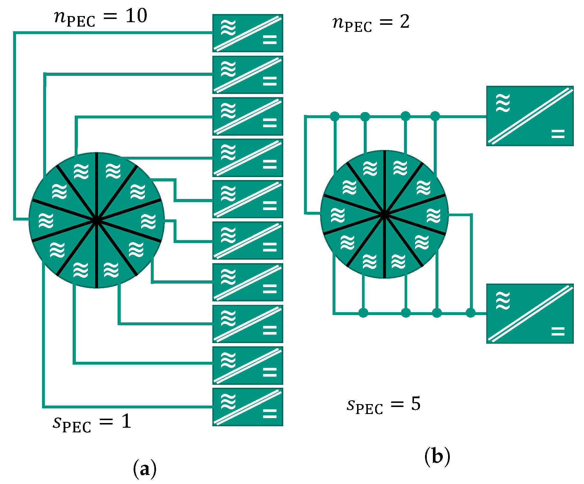
to one PEC and the remaining subset(s) to other, identical PECs. If
is the number of individual PECs and
is the number of parallel three-phase systems per PEC, then this requirement can be expressed through
At the same time, the PEC phase current
is given by
The bottom-right graph in
Figure 6 displays these possible machine/rectifier segmentation options, where each “row” corresponds to the pole pair concept with the same voltage in the bottom-left graph. The possible options per concept row are marked through different symbols. For example, a machine with
pole pairs provides
available three-phase systems according to (
12). With
A and (
13), the electrical power of such a generator can be segmented in four different ways, as shown in
Table 1. For better visualisation, not all available options for all investigated pole pairs are shown in the bottom-right graph of
Figure 6.
With these segmentation options, it is much easier to design a technically and economically feasible rectifier, as its phase current
can be matched to the current handling capabilities of available power semiconductors more easily, as can be seen when comparing the top-right and the bottom-right graphs of
Figure 6. Additionally, a segmentation of the output power of the generator to several rectifiers increases the system reliability by reducing the impact of single device failures and introduces the possibility to control the torque ripple of the generator within tighter limits.
6. Rectifier Concepts and Topologies for FSSGs
State-of-the-art PECs can be categorised into two main groups:
Conventional converters that are designed for a specific conversion task and usually try to minimise the number of functional components;
Modular or cell-based converters that combine multiple copies of a basic converter “cell” to address various conversion tasks and/or to enable a more flexible system.
Conventional converters tend to have a comparably low degree of complexity and fewer components than modular converters. Two examples of this group that will be discussed in
Section 6.1 are the B6 topology, consisting of six power semiconductors with a single DC capacitor, and the ANPC topology, consisting of 18 power semiconductors and a split DC capacitor.
Cell-based converters, which are discussed in
Section 6.2, tend to be more flexible and often offer additional benefits such as redundancy or improved power quality, but usually require more components and a more complex control system. They present the possibility to use lower-voltage semiconductors with current ratings that fit better to the relatively low FSSG phase currents, produce lower losses and can be operated at higher switching frequencies [
22]. Moreover, the increased number of voltage levels results in a better approximation of the sinusoidal AC voltages and therefore lower harmonics in the generator phase currents. Depending on the ratio of load current and harmonic content, this in turn can lead to lower AC losses in the HTS tape as well and opens possibilities to reduce the size of filters or to omit them entirely. Furthermore, assuming the same semiconductor technology, the resulting voltage slopes
can be reduced, resulting in lower insulation stress.
6.1. Conventional Converter Concepts
Suitable conventional converter concepts for the above-mentioned compromise for an FSSG can be identified directly through the bottom-right graph of
Figure 6. By transferring the envelopes of the top-right graph of
Figure 6 to its bottom-right graph, we can visually select the machine concepts that can be addressed with the envelope that corresponds to a given rectifier concept. The steps in the envelopes correspond to the different semiconductor voltage class applications surveyed in the upper graphs of
Figure 6. The marked machine options that fall below and to the left of the respective envelopes are candidates that make further investigations viable.
6.1.1. Two-Level Active Rectifiers
A standard B6 bridge rectifier (
Figure 7a) requires that each individual semiconductor can endure the maximum phase-to-phase voltage on its own. The solid black envelope in the bottom-right graph of
Figure 6 corresponds to this requirement, leading to the conclusion that this approach would not provide any viable options even for a generator with
p = 60 pole pairs, as the minimum possible voltage for this design is well above the operational voltage of individual 6.5 kV power semiconductor modules.
However, power semiconductors could be connected in series to distribute the voltage load of the generator to multiple devices, yet this distribution also has to be ensured during each switching process. The additional effort required to secure this voltage balancing both in the blocking state as well as during switching transients cannot be neglected and is rarely used in practical applications, because multi-level topologies in this case often offer a better alternative. It is therefore not advisable to use a B6 topology, even a series-connected one, for the investigated FSSG concepts.
6.1.2. Three-Level Active Rectifiers
Several multi-level topologies, such as an ANPC shown in
Figure 7b, offer an even voltage load between the individual semiconductors both during static and switching transient operation. The third voltage level also allows a better approximation of ideal sine waves, reducing the need for filter equipment. Rectifier concepts using multi-level topologies could enable the use of lower-voltage devices and/or the use of machine concepts with a lower number of pole pairs.
The dashed black envelope in the bottom-right graph of
Figure 6 shows the application limit of 3-level ANPC rectifiers for FSSG wind turbines. Due to the high voltages of the generator, 6.5 kV devices are required for this topology, enabling a match with concepts with at least
p ≥ 50…52 pole pairs. According to (
3), such designs are subjected to relatively large AC losses. Additionally, the high-voltage devices are limited to switching frequencies of a few hundred Hz to a few kHz at best. This topology provides a technical possibility to solve the interface problem, but its performance will certainly not be satisfactory—neither from the perspective of the FSSG nor from the perspective of the PEC.
Higher-level topologies can extend the voltage load capabilities of a PEC, but at the same time increase the complexity with little benefit regarding size, weight and efficiency of the PEC. For example, a 5-Level ANPC can in theory bear twice the voltage load of a 3-Level ANPC, but this approach would still require 6.5 kV devices to enable FSSG concepts with phase voltages below approximately 16 kV (see the dotted black line in the bottom-right graph of
Figure 6), corresponding to
p > 24 pole pairs. Devices with voltage ratings of 4.5 kV and 3.3 kV can also be used but only for FSSGs with higher numbers of pole pairs.
Additionally, higher-level topologies require non-negligible effort to balance the additional capacitors, which increases with the number of levels. It is therefore questionable if these conventional PEC design approaches can provide desirable effort to performance ratios for the investigated application.
6.2. Cell-Based Multi-Level Converters
Due to the specific requirements of the medium voltage FSSG and the above described difficulties resulting for a B6 or ANPC converter, multi-level topologies can present an interesting alternative. In this section, several multi-cell converters are therefore discussed in terms of their suitability for use with FSSGs.
Two scenarios are considered: one in which the generator is connected to a medium voltage (MV) AC grid through an inverter and a second one in which it is connected to a MV DC grid via a galvanically isolated DC/DC converter. For both scenarios, the three-phase AC voltage of the generator is first rectified using
rectifiers. These two scenarios are pictured in
Figure 8.
The common DC voltage link at the rectifier output provides a certain flexibility, because the same rectifier unit can be used for both scenarios. Therefore, only topologies which have a DC voltage link are considered here. These topologies can be constructed with single IGBTs or SiC-MOSFETs and provide a lower complexity and/or component count compared to topologies that require bidirectional blocking capabilities, e.g., current source inverters that require an additional diode [
23,
24].
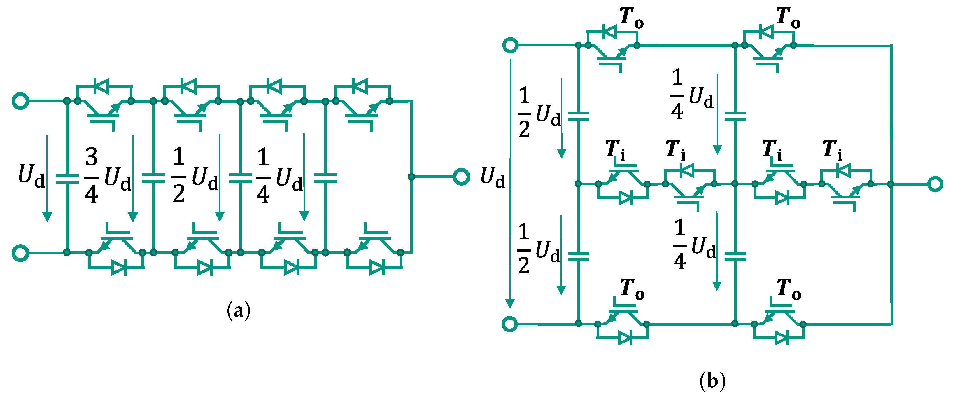
6.2.1. Flying Capacitor Converter
The flying capacitor (FC) converter was first introduced in [
25]. An example of its cell-like structure is pictured for one phase of a 5-Level FC in
Figure 9a. For
n levels it consists of
flying capacitors per phase and one common DC link capacitor. The flying capacitors have to be pre-charged before operation and their voltages have to be held at nominal voltage during operation, which results in a much higher modulation and balancing effort compared to a B6 converter and even in a higher effort compared to NPC converters. On the other hand, this topology limits the maximum voltage across each power semiconductor to the (
)th part of the DC link voltage. Thus, in comparison to topologies with a lower number of levels, semiconductors with a significantly lower blocking voltage can be used, which in turn enables higher switching frequencies.
The main disadvantage of this topology is the requirement of relatively expensive and bulky capacitors. This is especially problematic when the DC voltage is increased, because the stored energy in one capacitor grows with the square of the applied voltage, which then translates to larger capacitors. By using fast switching semiconductors and new operation principles, e.g., Quasi-Two-Level operation, the size of the capacitors can be reduced significantly, making this topology interesting for future MV applications [
26].
6.2.2. Stacked-Multi-Cell Converter
The stacked-multi-cell converter (SMC), introduced in [
27], is a further development of the FC topology. A number of
N FC converters are stacked on top of each other, resulting in a lower maximum voltage for each FC and therefore smaller and less expensive capacitors.
Figure 9b shows a 5-Level-SMC (
) and the resulting relative voltages of the FCs.
However, compared to the FC topology, the same number of semiconductors is required for the same number of voltage levels and the blocking voltage of the outer transistors
has to be twice as high (compare
Figure 9). Because the required blocking voltage of the inner transistors
is only half the required blocking voltage of the outer transistors
, each outer transistor can be theoretically replaced by a series connection of two transistors, so that the blocking voltage of all semiconductors is the same.
Several proposals can be found in literature to further improve this kind of converter, e.g., in [
28] by decreasing the number of required voltage sources or in [
29] by adding four low-frequency switches that are switched only twice per fundamental period to double the RMS value of the AC voltage and the number of voltage levels for the same DC link voltage.
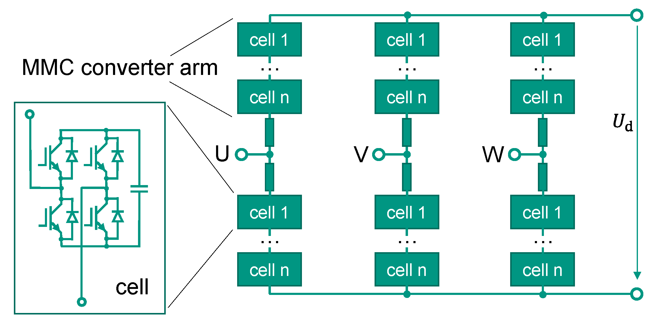
6.2.3. Modular Multi-Level Converter
The modular multi-level converter (MMC), pictured in
Figure 10, is known from high-voltage direct current (HVDC) electric power conversion applications. However, it can also be used for MV applications. The basic topology that converts a DC voltage to a three-phase AC voltage is introduced in [
30] and consists of two converter arms for each of the three phases. One arm itself is realised by a series connection of several cells. Each cell consists of a capacitor which can either be switched into the respective arm voltage or be bypassed using a half-bridge circuit. Alternatively, a full bridge circuit can be used, allowing for the insertion of a negative capacitor voltage as well. Due to the identical structure of the cells, the whole concept is highly modular and high voltages as well as a high number of voltage levels can be reached. Therefore, this topology enables low harmonics at the cost of a larger number of semiconductors. Hence, compared to the previously presented topologies, it could theoretically further reduce the HTS AC losses.
In future scenarios where the wind generator could be either directly connected to an MV AC or to an MV DC offshore grid, the converter has to ensure a galvanic isolation between the generator and the grid. Without such an isolation, the FSSG winding would require extensive isolation strength. Assuming a grounded stator and a symmetrical DC grid, this isolation would need to be designed for voltages in the range of the amplitude of the AC grid phase voltage or half of the DC grid voltage, respectively. All topologies mentioned above present no intrinsic galvanic isolation between their input and output. When using these topologies, the isolation has to be guaranteed on system level, e.g., with a transformer operated at grid frequency.
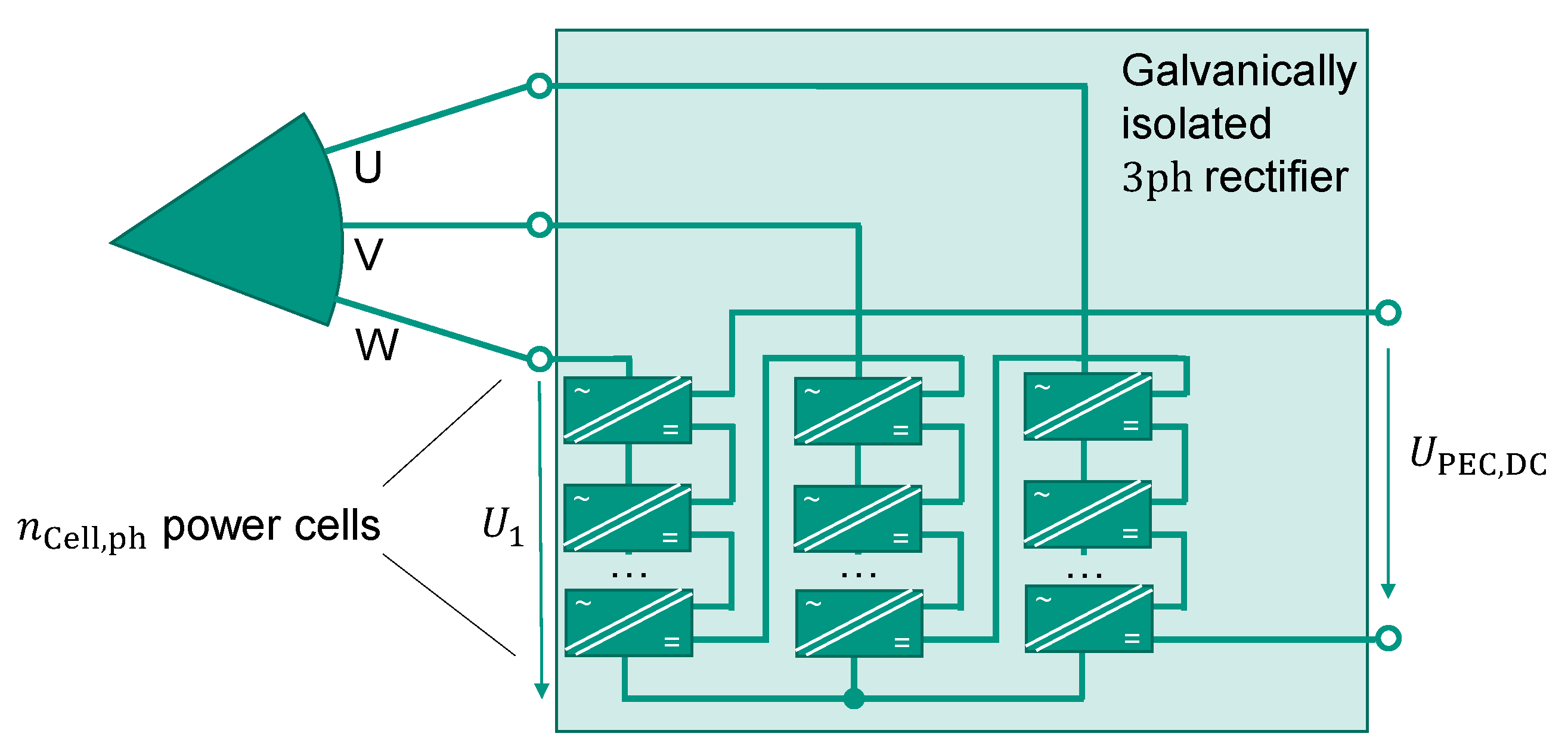
6.2.4. Cascaded Power Cells
Using a topology based on the cascaded H-bridge (CHB) converter introduced in [
31] allows for galvanic isolation at cell level. On the generator AC side,
H-bridges are connected in series to address high generator phase voltages even with low-voltage semiconductors. At the output of each H-bridge, a highly efficient DC/DC converter stage with a very high galvanic isolation is connected. The DC outputs can then again be connected in series to reach the required DC link or DC grid voltage.
Its high modularity makes this topology very interesting for a superconducting wind generator converter. It offers the possibility to use the same converter concept for different generator designs by simply matching the number of cells to the respective voltage requirements. Theoretically, a very high generator phase voltage can be realised, limited only by practical issues such as isolation clearances.
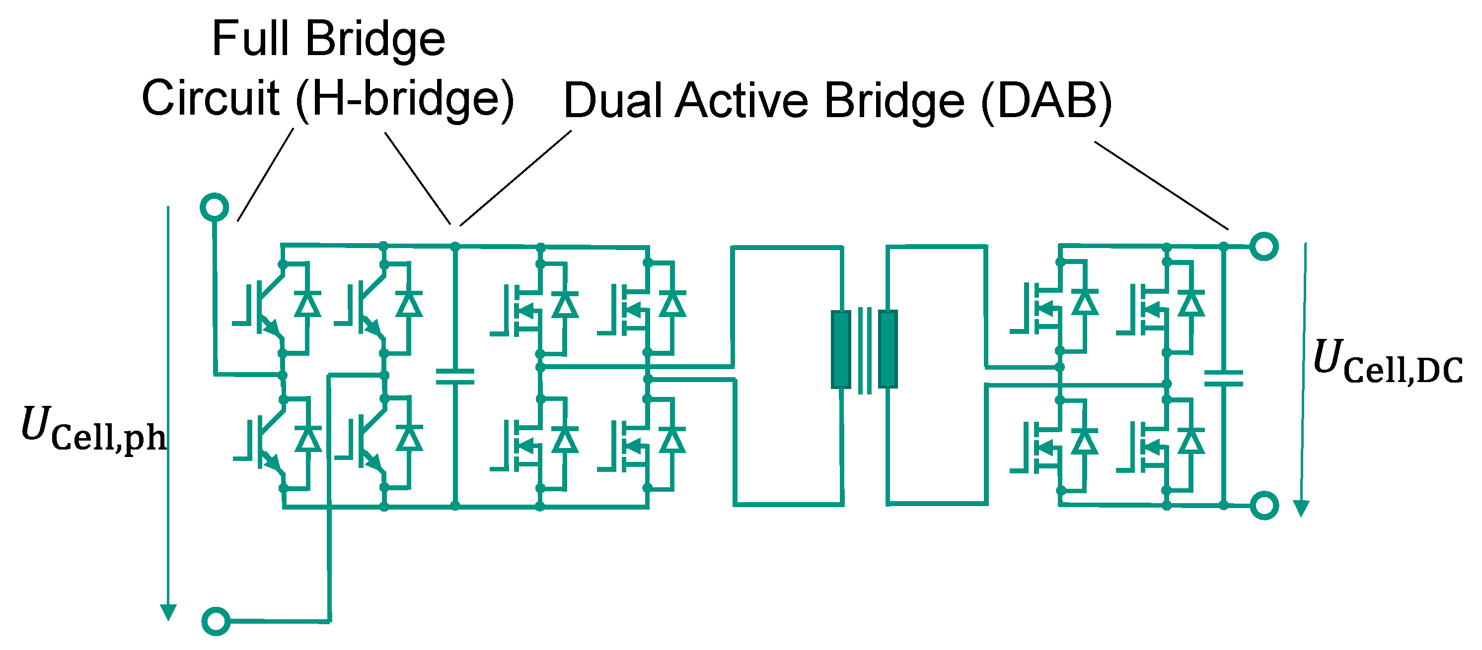
Figure 11 shows the topology for one three-phase system. The combination of an H-bridge and a DC/DC converter is called “power cell” in the following investigation.
In this example, all DC terminals are connected in series to enable the direct connection to a future MVDC grid. A proposal for the design of a single power cell is pictured in
Figure 12. On the AC side, the H-bridge rectifies the single-phase AC voltage of the generator. Because very low electric frequencies in the range of a few Hz (see (
2)) and rather large phase inductances in the range of several mH are expected for the FSSG (see
Figure 3), it is possible to realise this input rectifier stage with commercial IGBTs.
The DC/DC converter can be realised with different topologies, e.g., with a resonant converter such as an LLC or a CLLC converter or non-resonant options such as a dual active bridge (DAB). A single-phase and a three-phase DAB are proposed in [
32]. The single-phase DAB is compared with an LLC converter for a fixed, high conversion ratio in [
33], whereas [
34] compares a single-phase DAB with an LLC and a CLLC converter for a 1:1 conversion ratio. Hereinafter, a single-phase DAB is assumed for reasons of simplification. However, other topologies might show advantages compared to the DAB for that specific application and are worth investigating further.
The isolation in a DAB is provided using a medium frequency (MF) transformer and the semiconductors are usually switched with several tens of kHz. Due to lower switching losses compared to Si-IGBTs, SiC-MOSFETs are well suited for this task.
One challenge regarding this topology is the non-constant power input of one power cell, because it is a single-phase converter. If a constant power flow through the DAB is desired, the input DC link capacitor has to buffer the difference between the AC generator power and the constant power through the DAB, resulting in a reactive power at the input with double the electrical generator frequency . It is possible to use the capacitors on the primary and secondary side of the power cell to buffer the AC power ripple with a suitable control of the DAB if they are dimensioned accordingly. Alternatively, the power transfer through the DAB could be modulated to follow the single-phase AC power of the generator. A constant total DC power flow at the converter output is then realised by paralleling the DC outputs of the converters of all three generator phases.
Further challenges for this approach are the high isolation strength required for the MF transformers as well as the demand of high reliability in terms of isolation failure. With MF transformers, each transformer must provide a failure rate that is lower by a factor of compared to a topology with one central transformer to reach the same overall system failure rate. Despite these challenges, the proposed topology concept should be investigated further due to its high degree of modularity and its flexibility. One possible adaption to the FSSG application is presented in the next subsection.
6.2.5. Cascaded H-Bridge Concept for the FSSG
Due to their high availability even at lower rated currents, the following investigations of the Cascaded H-bridge concept are performed for 1200 V and 1700 V semiconductor modules. According to
Section 5.1 these semiconductors ensure working voltages of 720 V or 1020 V, respectively, which define the maximum DC link voltage
of each power cell. For sine-triangle modulation without overmodulation, this in turn is identical to the maximum possible AC voltage amplitude
of each power cell [
35].
Because the power cells of one phase are connected in series and the phases themselves are star connected, the sum of the individual power cell AC voltage amplitudes must be equal to or higher than the amplitude value of the generator phase voltage
, that is calculated with (
9) and (
11). The minimum number of series connected power cells can then be determined using
Assuming the exemplary values used in
Section 5 (
,
,
A and
MW), an FSSG phase voltage amplitude of
kV is calculated. Therefore, at least 15 power cells with 1200 V semiconductors or eleven power cells with 1700 V semiconductors are to be series connected per phase. A higher amount of cells is possible and will increase tolerance against failures. In case of a failure inside a single power cell—except for isolation failure of the transformer—the faulty cell could then be short circuited at the input and output, allowing the system to still operate at the nominal power. The minimum total number of power cells can be calculated using
As displayed in
Table 2 for a three-phase machine with ten branches and no direct branch parallelisation, this results in 450 or 330 cells for 1200 V or 1700 V semiconductors, respectively.
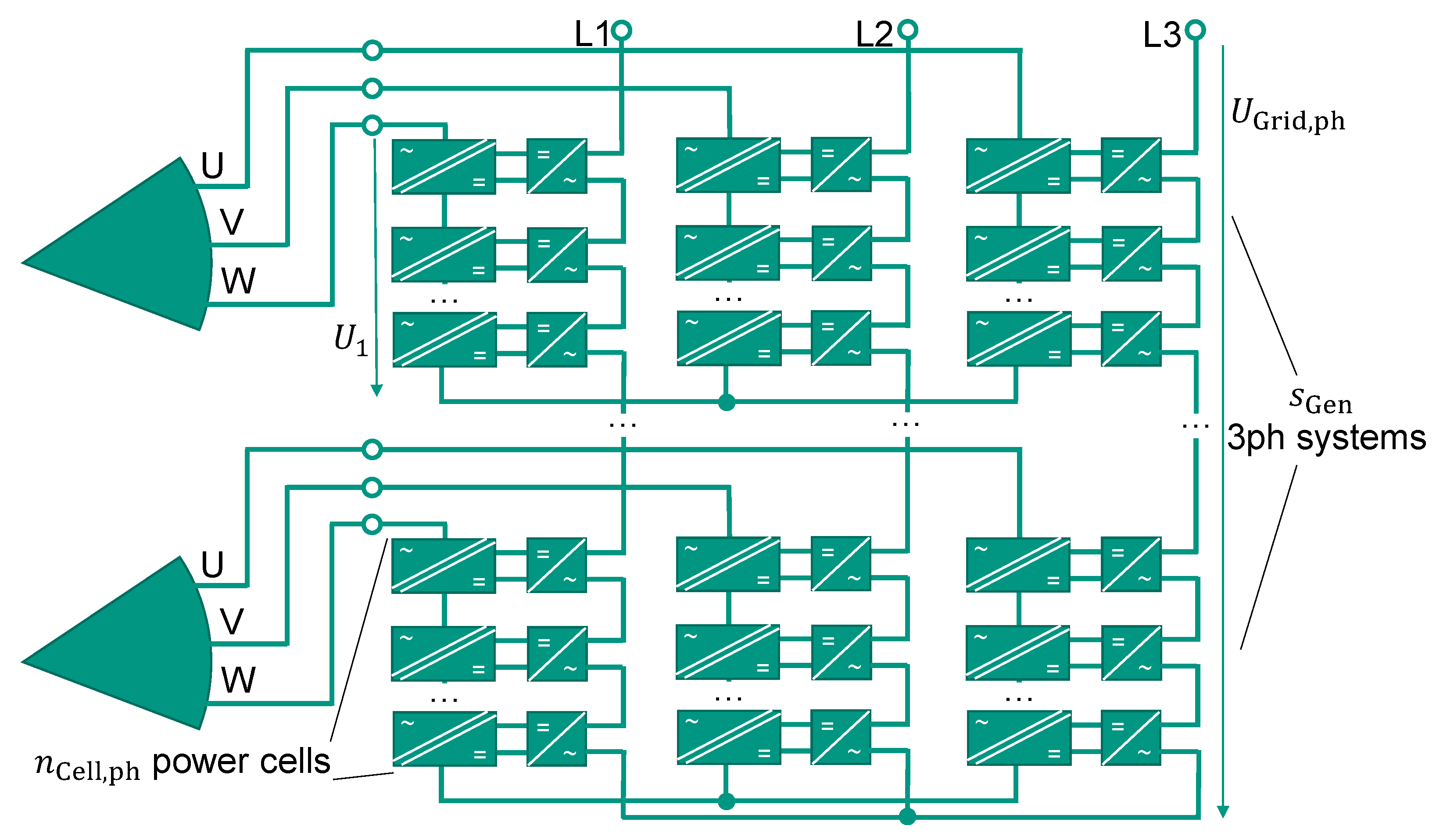
To reduce the number of power cells, several three-phase systems can be parallelised directly as illustrated in
Figure 13. This approach reduces the possibilities in the independent branch control but leads to a less complex converter design with higher currents per converter phase.
For a machine with ten three-phase systems, five parallel systems result in a converter phase current of 260 A, which is a common current rating for several commercial 1200 V and 1700 V SiC-MOSFET and Si-IGBT semiconductor modules. The minimum number of cells can then be reduced down to 90 or 66 cells for 1200 V or 1700 V semiconductors, respectively (See
Table 2).
Assuming a 1:1 transfer ratio of the DAB and a series connection of all power cells on the DC side, this concept can provide a maximum total DC voltage
according to
For the above mentioned exemplary FSSG, this would lead to the maximum total DC voltages displayed in
Table 2. Lower total DC voltages can be reached by parallelising certain power cell outputs
, three-phase converter outputs
or by adapting the transfer ratio of the DAB. The latter can be achieved by changing the winding turns ratio of the MF transformer or by modifying the modulation of the DAB [
32]. Higher voltages could be reached by increasing the number of cells per phase
. However, for all types of power cells a direct connection on the DC side to a MV DC grid with, e.g., ±25 kV is theoretically possible for the exemplary generator concept with ten branches.
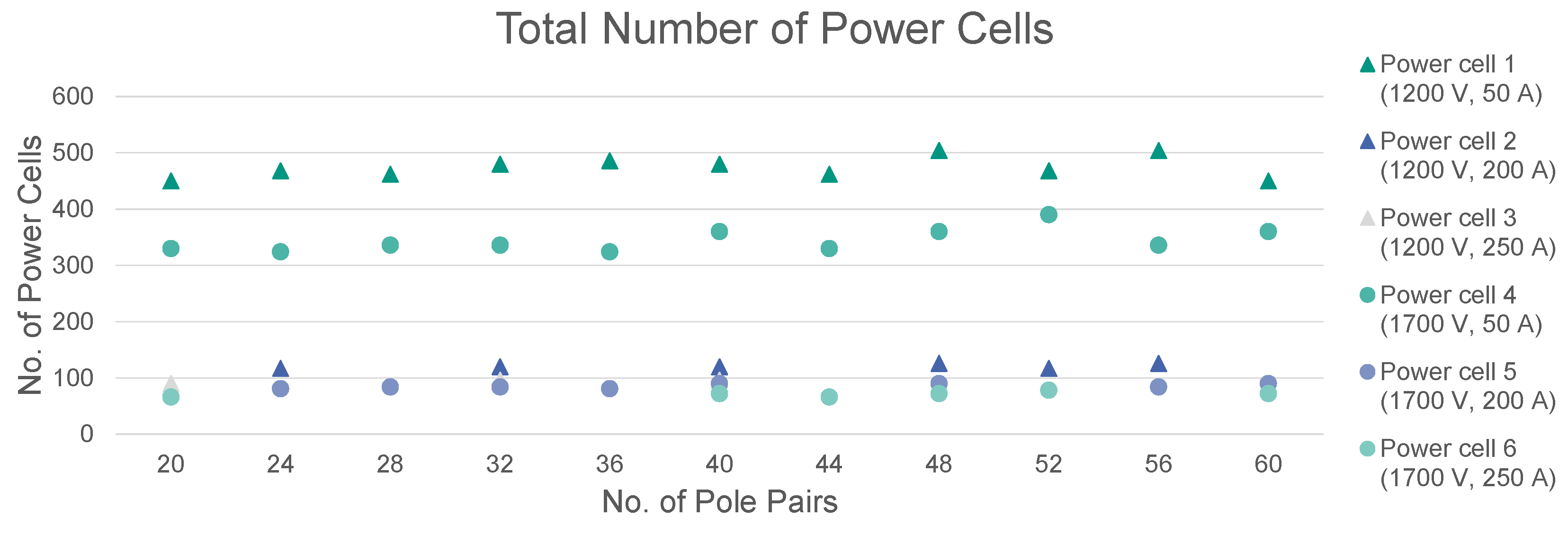
The concept can be easily adapted to generators with different pole pair numbers or number of branches, respectively. Using (
14), (
15) and the respective cell voltage maximum possible AC amplitudes
, the necessary minimum total number of power cells for the 10 MW FSSG can be calculated. The resulting values are illustrated in
Figure 14.
It is evident that the number of power cells is hardly dependent on the number of pole pairs or three-phase systems. The generator phase voltage
decreases with
according to (
9) and (
11). At the same time, the number of three-phase converters
increases with
((
12) with constant
) so that the total number of power cells stays nearly constant. The deviations result from the ceiling function in (
14). For some FSSG concepts (corresponding to a certain numbers of pole pairs), not all power cell concepts are possible due to the fact that the ratio of the number of three-phase systems
and parallel three-phase systems per converter
would not be an integer. However, with an appropriate choice of pole pairs, this topology offers the possibility to use standard 1200 V or 1700 V semiconductors over a wide range of number of pole pairs and three-phase systems, even if an unusual combination of large phase voltage and low phase current is present.
6.2.6. Realising an AC Grid Connection
Besides the direct connection to a MV DC grid, the generator could also be connected to an MV AC grid. To achieve this, the power cells could be extended by an additional single-phase AC inverter at the output, which can be implemented with 1200 V or 1700 V components. The AC outputs are then connected in series to reach the grid phase voltage.
Figure 15 shows an exemplary circuit that pictures the basic idea. As for the DC grid connection, not all outputs per phase need to be connected in series. It is also conceivable to parallelise several three-phase system outputs, provided that all sets are used and all subsystems are identical.
If a constant power flow over the DABs is required, this solution shows a high demand of reactive power on both sides of the converter: on the machine side with double the electrical generator frequency
(
2); on the grid side with double the grid frequency
. Accordingly, the required energy storage can be disadvantageous compared to other concepts or operations.
Another possibility is the use of a central DC link at the output of all DABs, combined with a single common grid inverter. Using this configuration, the output H-bridges from above are not necessary and with an appropriate series or parallel connection of the power cell DC outputs, the voltage of the central DC link can be designed to be in the same range as the AC grid voltage. One possible topology for the grid inverter could be the above mentioned MMC, but other topologies can be viable as well, depending on the grid voltage and the grid-side requirements for the inverter, e.g., fault ride through capability. Those investigations are not the subject of this study.
In summary, the proposed multi-cell topology based on series connected power cells, each consisting of an H-bridge and a DAB, is well-suited as a rectifier and galvanic isolation unit for the FSSG application. Because it consists of low-voltage, low-current power semiconductors, it can be optimised for the low phase currents of the FSSG. Despite the challenges of the double-frequency reactive power and the high isolation and failure rate requirements on the MF transformer, this topology is worth investigating further, especially due to its high modularity, which allows for the easy adaptation to various generator designs.
7. Conclusions
To make use of the potential of superconductors in wind power generators, the design process of an FSSG has to consider the AC losses of the HTS winding. Only a few design measures enable the reduction in these losses, but they can cause conflicts with the design of corresponding PECs. This aspect has not yet been discussed in literature so far. Therefore, this study highlights the interactions between the design of an FSSG and its PEC.
The first sections discuss the general dependencies of the AC losses on the generator design. The AC loss reduction can be achieved through the use of narrow HTS tapes, which operate at very low coil currents, and by a reduction in the electric frequency and the perpendicular field strength. The frequency is influenced by the number of pole pairs whereas the perpendicular field strength is coupled to the pole pitch. Both of these design options are investigated by their respective parameter studies. The parameter optimisation leads to FSSG designs with high output voltages, low output currents and low electric frequencies which have to be handled by their PEC.
After these generator-related investigations, the following sections focused on the influence of such unusual parameter combinations on standard PEC designs. It was found that available power semiconductor modules can supply the necessary blocking voltage if multi-level topologies, e.g., an ANPC, are used. However, the current utilisation factor of these semiconductor modules would be poor due to the low phase currents. Additionally, the corresponding converter concepts tend to require higher numbers of pole pairs for the generator, which would lead to higher AC losses inside the HTS tape. Therefore, multi-cell designs are discussed in the last section as an alternative to standard PEC topologies. Among several concepts, a topology based on series connected power cells is presented, which offers practicable solutions with available power semiconductors at the cost of a larger component count and a higher system complexity.
Overall, the design of PECs for FSSGs is challenging, but there are technical solutions available. This study provides insight on how to consider the requirements of both an FSSG and its PEC and presents guidance for future designs.

 ,
, 


