
Permanent Magnet Generator for a Gearless Backyard Wind Turbine


1
Department of Industrial Electrical Engineering and Automatic Control, Kielce University of Technology, Tysiąclecia Państwa Polskiego Str. 7, 25-314 Kielce, Poland
2
Faculty of Environmental, Geomatic and Energy Engineering, Kielce University of Technology, Tysiąclecia Państwa Polskiego Str. 7, 25-314 Kielce, Poland
*
Author to whom correspondence should be addressed.
Energies 2022, 15(10), 3826; https://0-doi-org.brum.beds.ac.uk/10.3390/en15103826
Submission received: 2 April 2022
/
Revised: 15 May 2022
/
Accepted: 17 May 2022
/
Published: 23 May 2022
(This article belongs to the Special Issue The Development of Renewable Energies in Poland)
Abstract
:This paper presents the design of a permanent magnet generator for a gearless backyard wind turbine. The magnetisation characteristics of the rotor steel and the stator at different field strength ranges were considered at the design stage and mathematically described using a model in Matlab. The detailed calculations and the design of the planar model were carried out using FEMM software. The high-quality results obtained from the calculations shown in the paper made it possible to make a real model of the generator. This paper presents views of the stator package, the rotor, the entire generator and selected test results. The parameter of this turbine that distinguishes it from a wide range of manufactured generators is its low, non-standard rotational speed and low breakaway torque, which allows the power plant to start in winds of approximately 2 m/s. Other advantages of this generator is its low weight resulting from the use of a light rotor and light alloys for the generator housing.
1. Introduction
Rising electricity prices are driving an increased interest in renewable and clean energy sources. One such source is wind, available to virtually all energy consumers. The rotational speed of the wind turbine depends on its dimensions, the diameter of the turbine and the wind speed. Many wind farms use gears that increase the speed of rotation. In such cases, the generators used in power plants may have smaller dimensions at a given power (power is the product of torque and rotational speed, and the torque depends on the dimensions of the generator). The use of a speed-increasing gearbox reduces the size of the generator, but the final efficiency of the wind turbine is also reduced. This increases the total cost of the wind turbine, noise and maintenance costs. In order to reduce costs and increase the efficiency of converting wind energy into electricity in small wind farms, gearless designs were developed, in which the wind turbine is mounted directly on the generator shaft. Such direct drive solutions enforce the design of multi-pole generators with low rotational speeds resulting from the large diameter of the generator. The increase in diameter causes an increase in the generator’s weight. The leading manufacturer of low-speed generators is the French company ALXION, whose generators are offered as built-in machines without a shaft. The analysis of this topology was presented in the grant report: ‘Comprehensive solution of a small variable-speed wind turbine with an energy storage module for distributed energy applications’ development project: N R01 0015 06/2009, Warsaw University of Technology, and thus is not presented in this work. We might add that the presented design was compared with a solution containing 40 poles on the rotor and 39 rows in the stator, a solution that offers even less coupling torque but introduces asymmetry, which results in high magnetic tension and a number of unfavourable phenomena associated with it. With a high radial load on the bearings, uneven air gap associated with clearances occur in the machine, with noise and vibration occurring during operation.
In order to use the generator manufactured by this company, it is necessary to obtain a mechanical connection between the wind turbine rotor and the generator’s rotor, which generally causes considerable problems to an individual customer because the wind turbines offered on the market are adapted to work with rotating shafts of generators. The aim of this paper is to develop a generator design with a shaft on which a wind turbine can be directly placed. The designed generator should also work well for wind turbines with a horizontal and vertical axis of rotation. An additional aim is to reduce the breakaway torque to less than 1% of the rated torque (the best designs torque is at 1.5%). Reducing this torque has a direct impact on wind turbine starts in low-speed winds. Due to the location of the generator on a high mast, its weight should be as low as possible. This paper presents the design and selected test results of a generator excited by neodymium magnets with high magnetic energy, and intended for a gearless home wind turbine. The parameters that distinguish it from the wide range of currently manufactured generators are its low, non-standard rotational speed, resulting from a large number of magnetic poles (36 poles), and extremely low cogging torque allowing the power plant to be started in wind speeds of approx. 2 m/s. Other advantages of this generator are its low weight resulting from the use of a light ring-shaped rotor and the use of light alloys for generator casing. The designed generator can be also used in small hydropower plants equipped with slowly rotating water wheels.
2. Design Assumptions
The following basic assumptions defining the rated parameters were made when designing the generator:
| - | Power | 4 kW |
| - | Output voltage | 3X380 V |
| - | Speed | 167 rpm |
| - | Efficiency | minimum 85% |
| - | No. of phases | 3 |
| - | Output voltage frequency | 50 Hz |
| - | Cogging torque | less 1% |
| - | Rated torque resulting from power and rotational speed | 230 Nm |
The low rotational speed is due to the use of a wind turbine (HAWT), with a horizontal axis of rotation and the diameter of 5 m, to drive the generator, and as indicated by the experience gained by the author, this is the speed achieved by the mentioned turbine in wind speeds of approximately 8 m/s (winds with higher speeds are exceedingly rare at low altitudes). The low speed is due to the parameters of the wind turbine driving the generator.
One extremely important assumed parameter is the efficiency of the generator. Determining the efficiency at the required level significantly affects the mass of the winding and the mass of the magnetic materials of the machine [1,2,3,4]. If we assume low thermal losses (low winding resistance), then we have to use a winding wire of a larger diameter, which directly increases the weight of the generator. The use of a small diameter wire reduces the weight, increases heat losses, but requires heat dissipation, which is associated with an increase in heat dissipation surfaces. A slight increase in efficiency often comes at the cost of increasing both the weight and price of the generator. It is a constant dilemma for designers and manufacturers of electrical machines.
3. Generator Design
The main problem with multipolar permanent magnet machines is the high cogging torque resulting from the high number of poles. The high cogging torque causes machine vibrations during operation as well as associated noise. The simplest and most common way to minimize this torque is to use a stator with skewed slots [5,6,7]. However, it can be used in cases where the length of the stator lamination stack is significant. With a small stack length and skewed slots, there is a clear reduction in the usable area of the slot and it is difficult to place the winding in the slot. Another popular way to minimize the cogging torque is to use skewed or pseudo-skewed (several magnets along the length of the rotor offset from each other by a certain angle) magnets [8,9,10,11,12]. This solution requires the use of magnet bonding devices and does not produce results comparable to skewed stator teeth, and the bonding process itself is very labour-intensive. Another common method applied to reduce the cogging torque is to asymmetrically distribute the magnets on the rotor surface [2,4,13,14], or an asymmetrical magnetic circuit of the stator [15,16,17]. In such cases, the difficulties with balancing the rotor or shaft vibration due to the unbalanced stator and the occurrence of torque ripples are observed. In the presented design, the reduction in cogging torque was achieved by using a non-typical, odd number of stator teeth differing from the number of rotor magnetic poles by a value of three [15].
The designed generator has a classic design; the stator consists of a core made of a stack of electrical sheets and a winding. The rotor consists of a solid steel core to which arch surface-permanent N38H magnets are bonded. The generator uses a two-layer fractional slot, concentrated winding with a single slot pitch. For this reason, the number of stator slots is close to and slightly larger than the number of poles.
In the design of the generator, certain materials with the following magnetisation curves were adopted in Table 1:
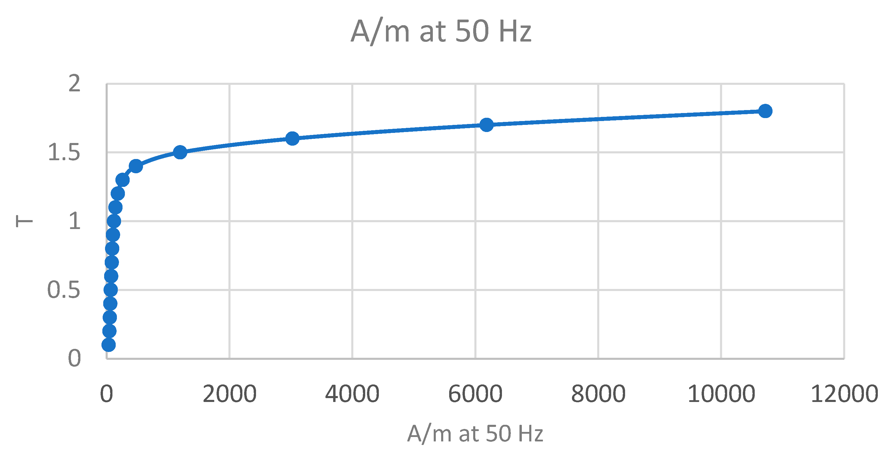
In order to increase the range of the characteristics to the induction value , the characteristics were extrapolated using the interp1 function in the Matlab environment, and the corrected induction and magnetic field strength vectors were recorded. The extrapolation results are presented below. The magnetization characteristics of steel in different field strength ranges are pre-drawn in Figure 1.
The Curve Fitting Tool in the Matlab environment was used to determine the equation of characteristics of the dependence of induction on magnetic field strength for different materials. The following general equation was determined by analysing different variants of steel magnetisation:
where:
- Bk—magnetic induction;
- Hk—magnetic field strength.
The dynamic magnetisation characteristics of steel for the data provided by the manufacturer are described by the formula:
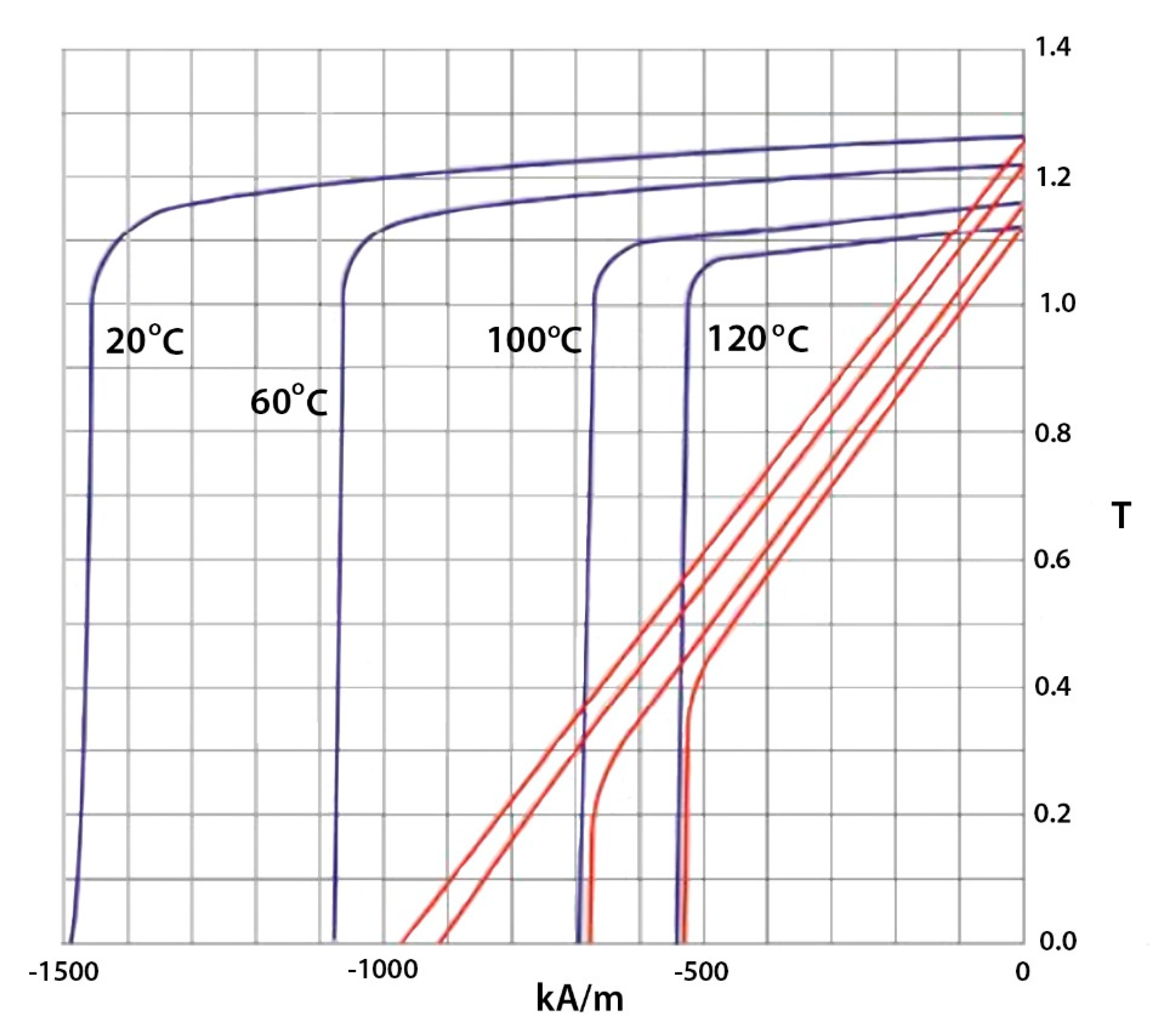
The generator uses an N38H magnet, for which the following demagnetisation characteristics for specific temperatures apply [18]. Demagnetisation characteristics of the N38H magnet is shown in Figure 2.
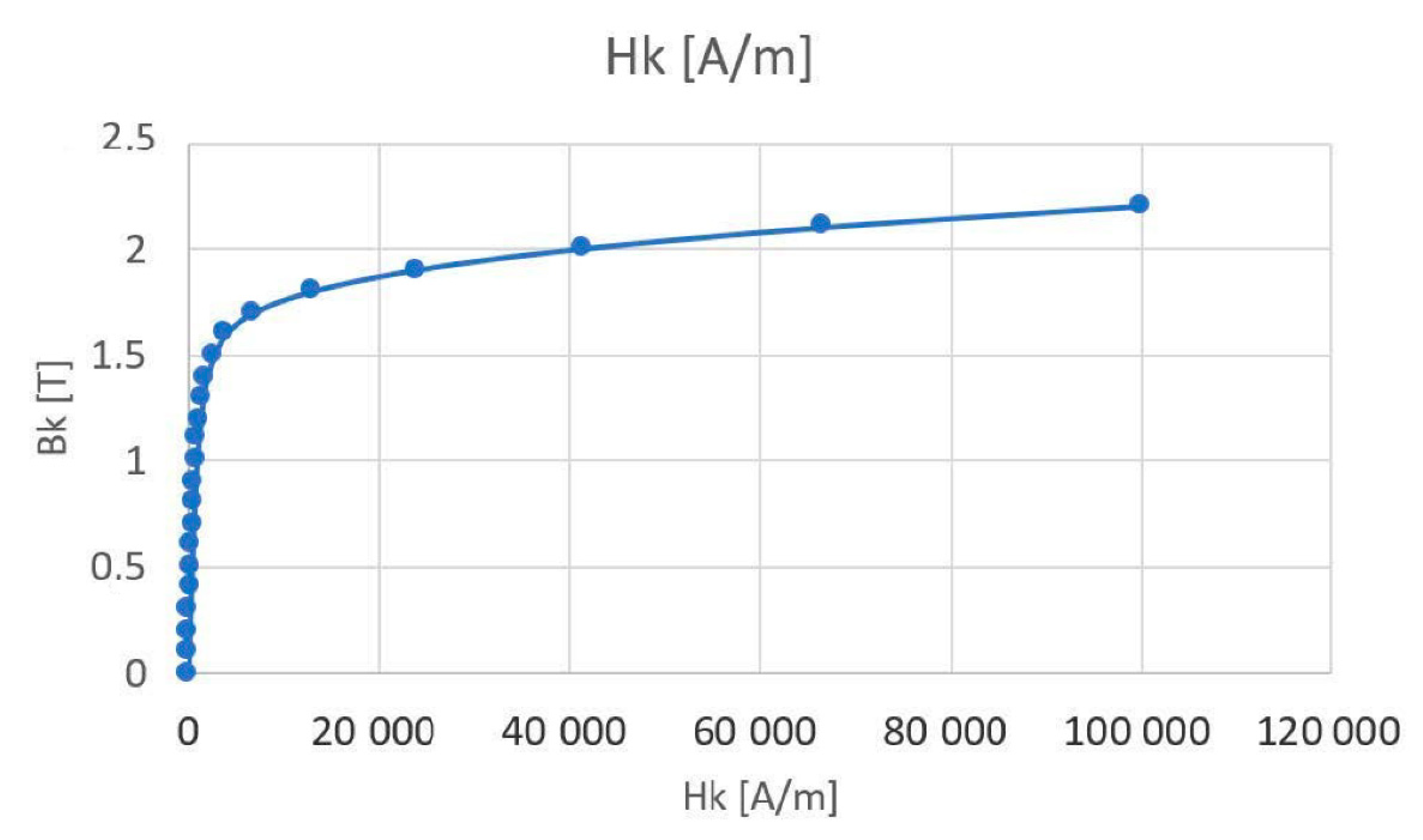
An M350-50A electrical sheet was used for the stator core of the generator. The loss and magnetisation characteristics were determined from the parameters provided by the manufacturer. The magnetic characteristics used in further calculations are presented below – The results are presented in Table 2.
Magnetisation characteristics of the M350-50A sheet metal are shown in Figure 3.
The dynamic magnetisation characteristics of M350-50A plates for the data provided by the manufacturer are described by the formula:
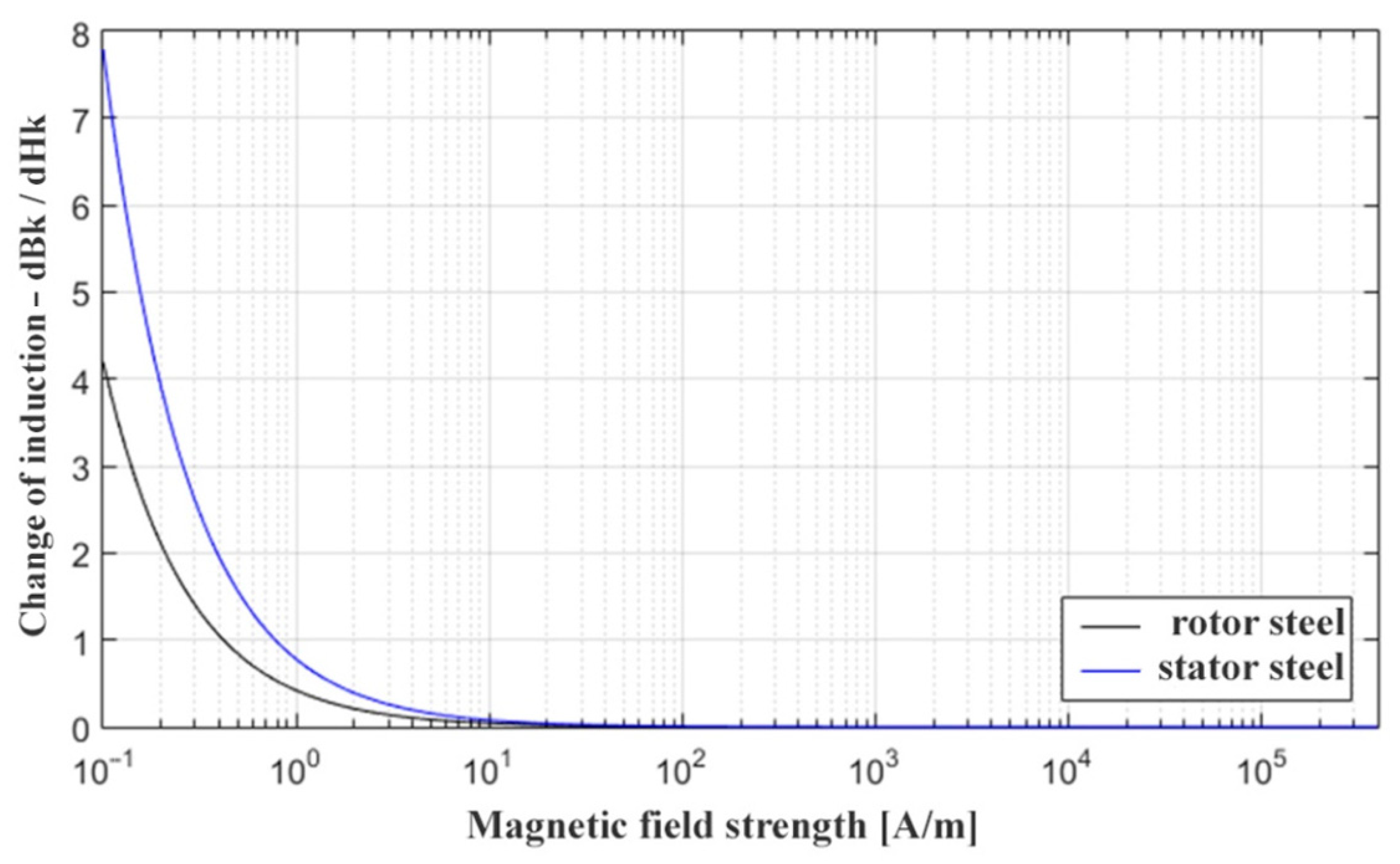
The dynamic magnetisation characteristics of the rotor and stator steel are shown in Figure 4.
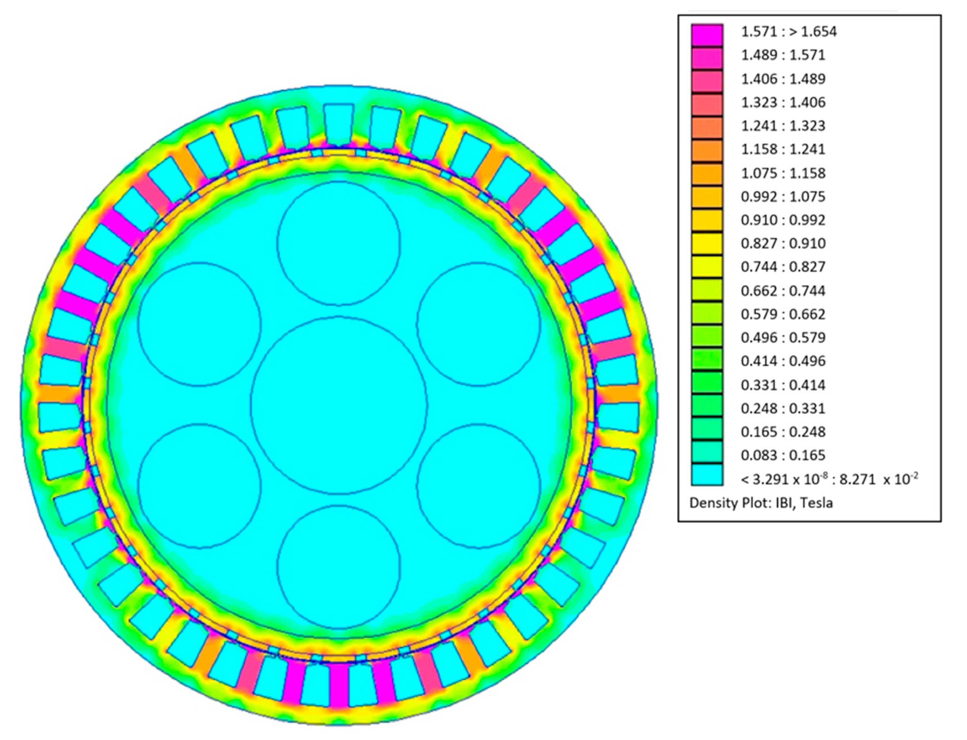
Flat model design calculations were performed using FEMM 4.2 software. This program uses the finite element method to calculate the given magnetic circuit. The calculation was used to determine the dimensions of the magnetic circuit, the number of winding turns, and the dimensions of the magnets. The following figure shows the geometry of the target generator magnetic circuit and the magnetic induction image in the elements of this circuit for the selected shaft position. Distribution of induction in the magnetic circuit of the generator show in Figure 5.
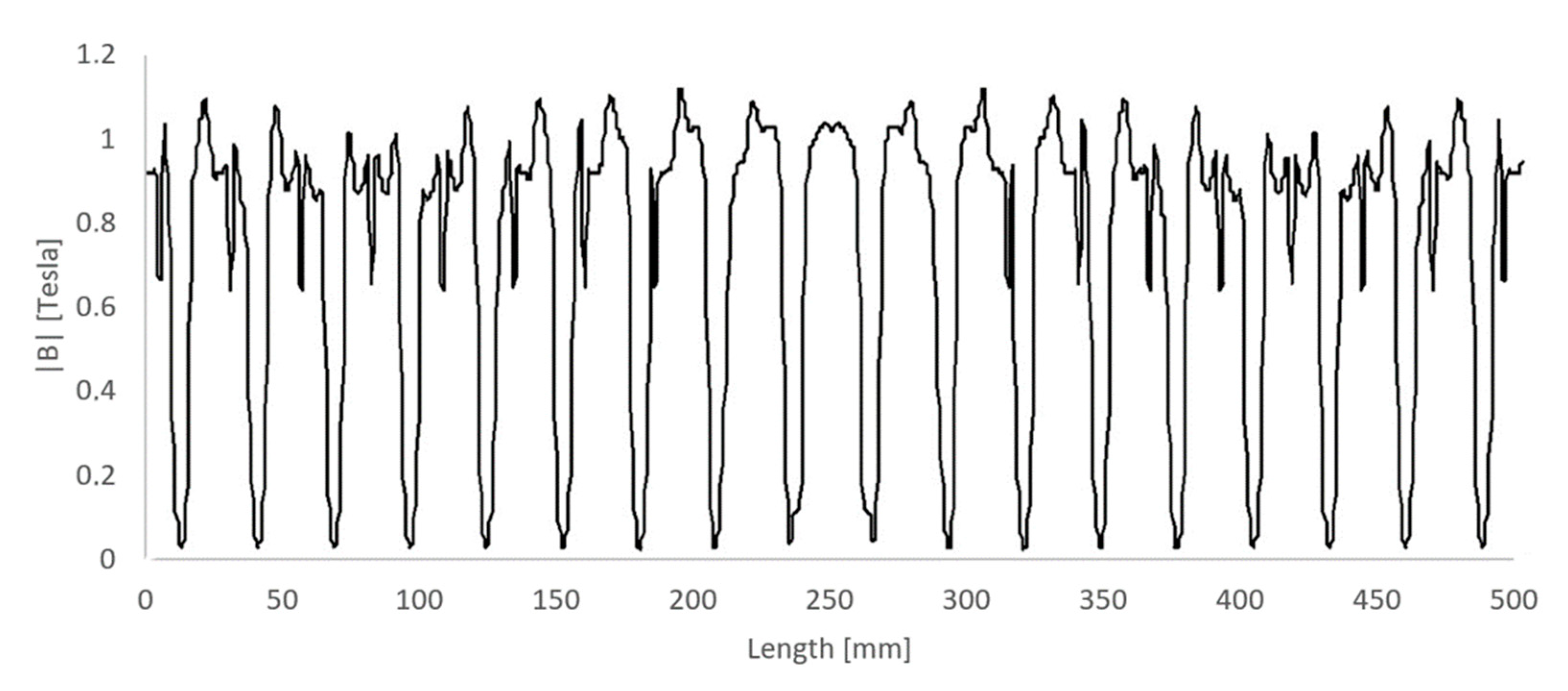
The induction value in the air gap of the generator in the range of about 180° show in Figure 6.
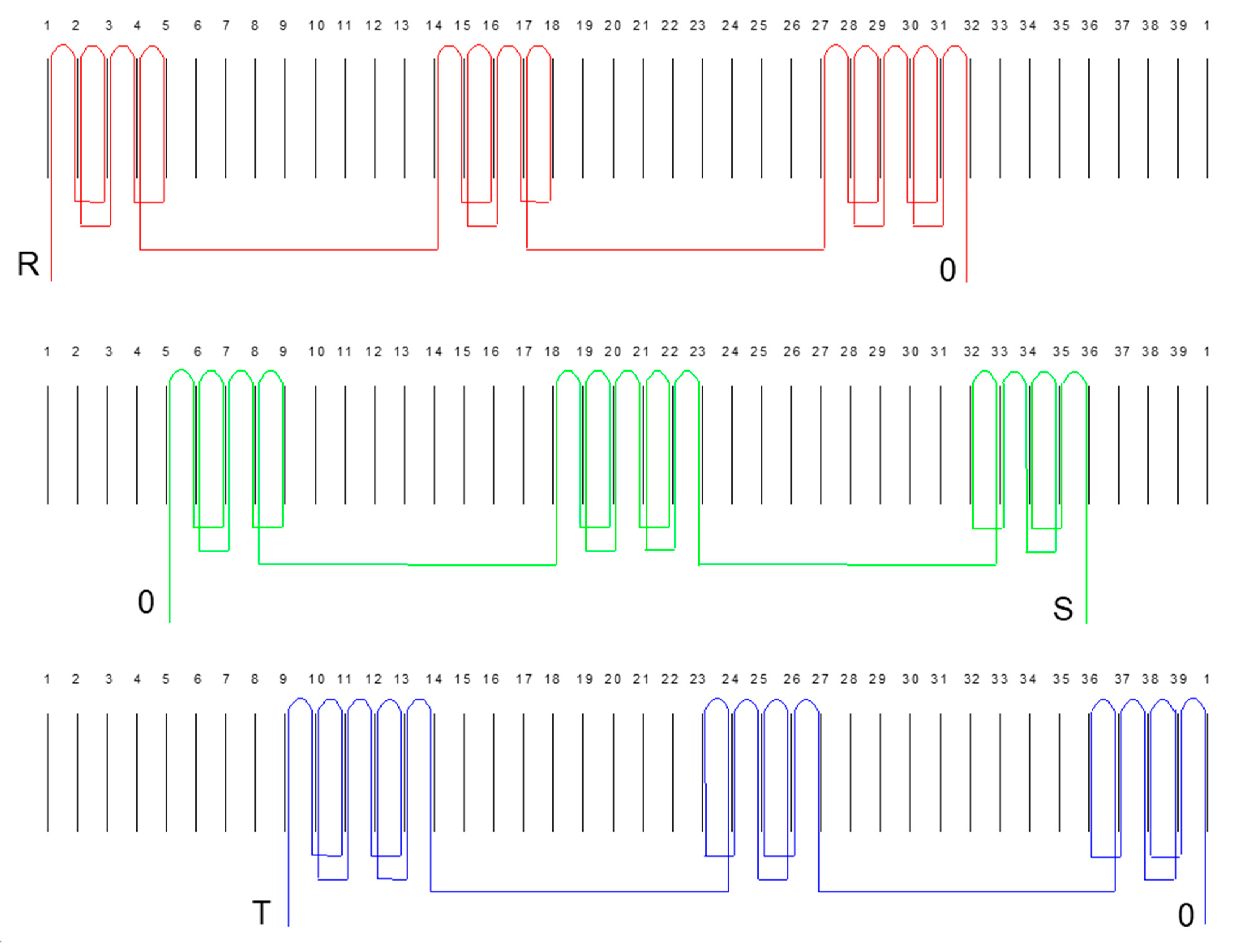
As can be seen, the value of induction in the magnetic circuit of the generator does not exceed 1.6 T in any of the circuit elements. Therefore, the weight of the generator can be reduced by reducing the dimensions of selected parts of the magnetic circuit. However, such reduction results in larger losses in the magnetic circuit and the deterioration of cooling conditions of the machine (the design of any electrical machine is always a compromise between the efficiency of the machine and the cost of its production). Additionally, the reduction in the dimensions of the magnetic circuit is not always possible for technological reasons (when sheets are made using punch dies, it is necessary to maintain the appropriate widths at which the sheets are held by the die). An important step is constructing the stator winding. In multipolar machines, concentrated windings are most commonly made as separate coils on the stator teeth [2,8]. This method of making the winding favours a low weight of the winding, because then the winding faces are reduced to the maximum, and there are short face connections, which are mostly located between the coils mounted on the adjacent teeth. With the adopted method of reducing the cogging torque [15], the number of stator slots is 39, which is an unusual number in electric machines. This mutual arrangement of slots and magnets results in local magnetic tension forces that cancel each other out due to their uniform distribution around the circumference of the rotor [17,18]. This arrangement also enforces the unusual way of connecting the winding coils shown in Figure 7.
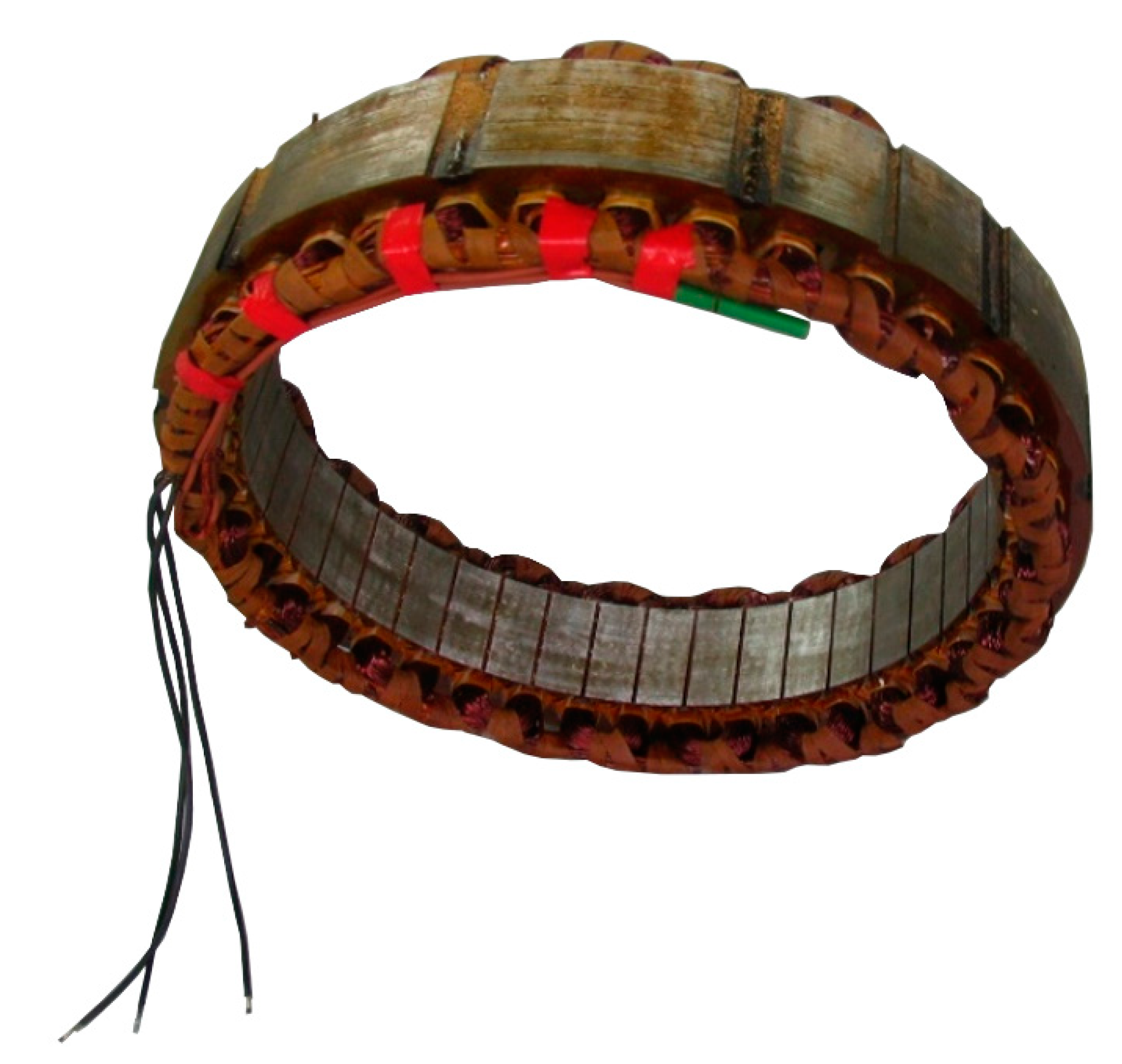
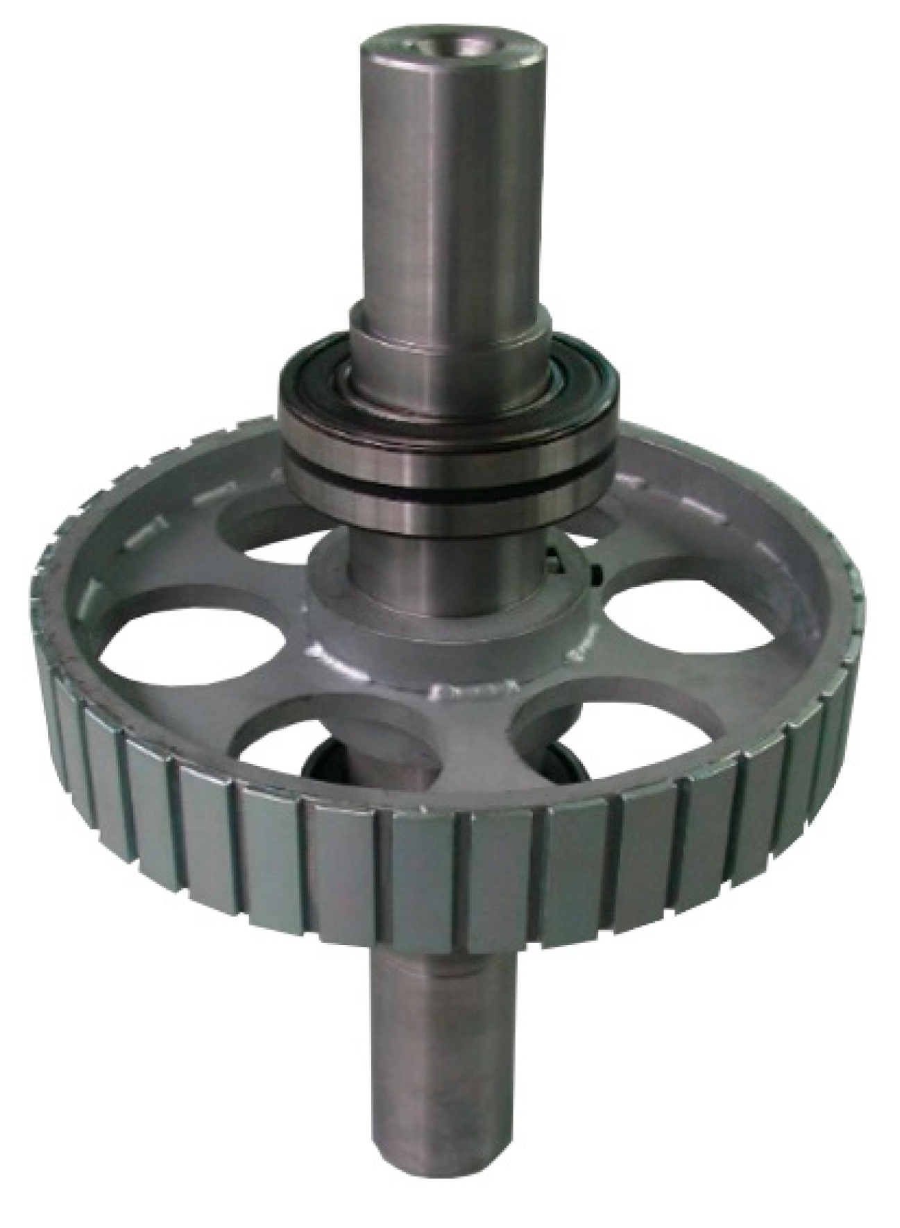
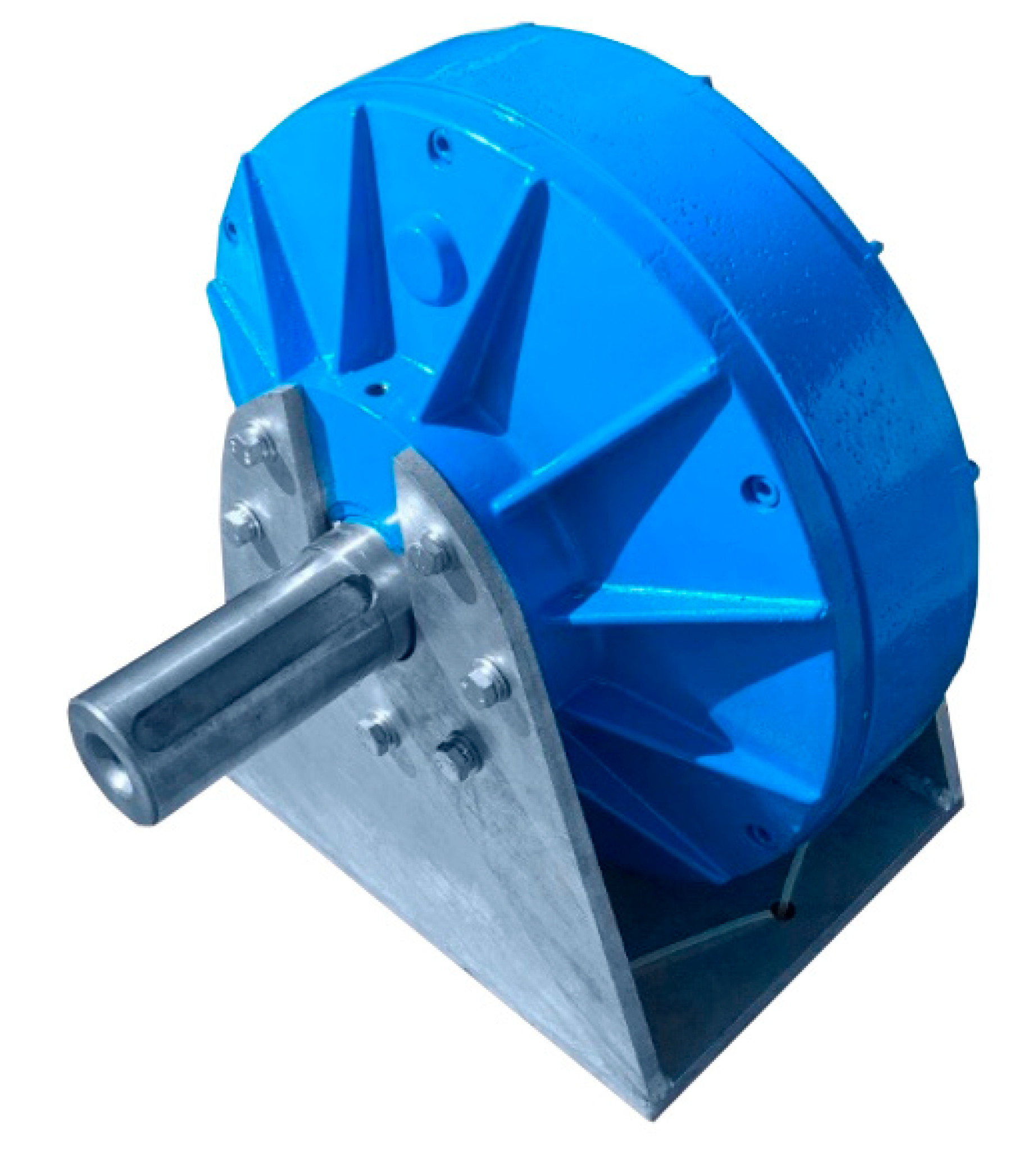
Due to the individual nature of the generator, a stator stack was fabricated using the laser cutting method. The sheets packaged in a bundle form the stator’s magnetic circuit. The next step consisted of the stator’s winding and the lamination process. Finally, the stator was placed in the casing. The casing is made of thin-walled cast aluminium and is ribbed to increase chassis rigidity and improve heat dissipation to the environment. The rotor of the generator has the shape of a circle with a steel rim on which neodymium magnets are glued [19,20,21,22]. The magnets are 5 mm high, 20 mm wide, have ring-shaped segments and are radially magnetised. The length of the magnets is 60 mm and is equal to the height of the stator sheet package. The rotor diameter with the magnets glued on is 325 mm. The rotor with bonded magnets was designed as a wheel with a steel rim (as shown in Figure 8). Six circular holes were made in the plate holding the rim with magnets to reduce the rotor’s weight. The rotor is supported in the casing by two spherical roller bearings capable of supporting high mechanical loads occurring in gusts of wind. These bearings also carry high axial forces, which are important in the case of cooperation between the generator and a wind turbine with a vertical axis of rotation. The rotor shaft is hollow in order to reduce the weight and has a diameter of 80 mm; this is so large due to the mechanical loads from the wind turbine. The casing is sealed by two sealing rings located near the bearings. The generator has an outer diameter of 470 mm and a weight of 72 kg. The generator winding is connected in a star whose ends are led out in the casing through a cable connector, ensuring a high tightness. The two-sided exit of the generator shaft enables the attachment of a wind turbine on one side, and a brake stopping the turbine in case of failure or too strong a wind on the other side. The following Figure 9 and Figure 10 show a view of the wound stator stack, a view of the rotor, and a view of the entire generator in a base that can be placed directly into the wind turbine nacelle.
4. Selected Test Results
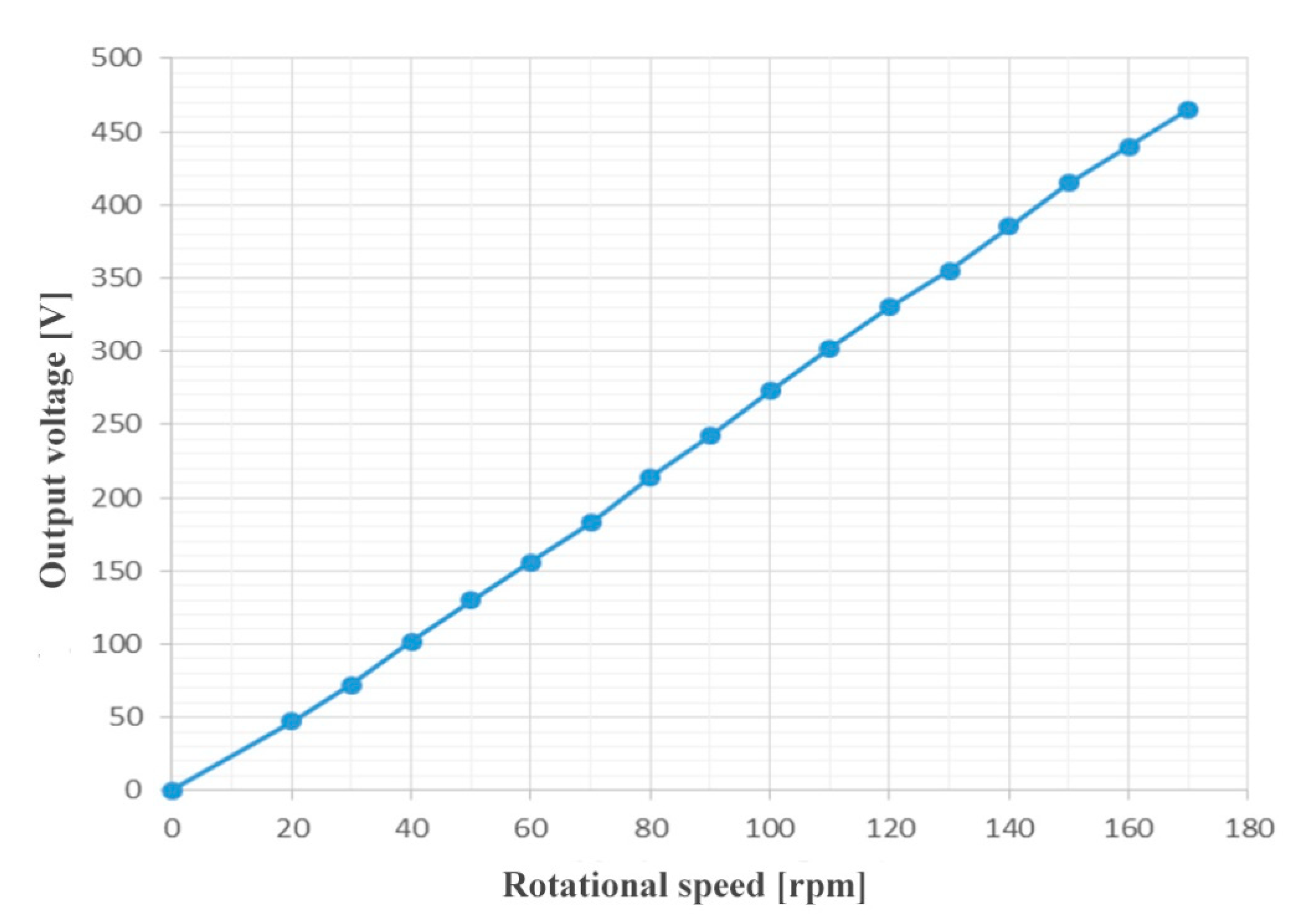
Basic laboratory tests of the prototype generator were conducted. These included measurements of cogging torque, idle voltage as a function of speed, and output voltage as a function of load at rated speed. The tested generator was driven through a gearbox by an asynchronous squirrel-cage motor powered by an inverter. The generator was resistively and symmetrically loaded in each of the phases; the load was the system of bulbs and slide resistors. During the measurements, a constant rotational speed of 170 rpm was maintained and the generator was gradually loaded to a current value of 6.5 A. The results of these measurements. This test was carried out after an hour of operation of the generator after heating. The measured, fixed winding temperature reached 95 °C. The results of the idle test are shown in Figure 11. As expected, the voltage linearly changed as a function of rotational speed, and at a speed of 170 rpm, reached 446 V. The maximum value of the cogging torque was measured using a balanced lever and precision weights. One end of the lever was equipped with a weighing pan into which precise weights were inserted. The lever arm was 30 cm. The coupling moment was obtained by multiplying the lever arm by the value of the weights where the rotor movement took place. Thanks to the appropriate design of the generator, the shaft led from both sides; it was possible to measure its efficiency without using a torque meter. The generator was suspended on external bearings, and the lever braking these bearings pressed on the scale. The braking torque calculated from the arm of this lever and the weight indications multiplied by the rotational speed determined the mechanical power supplied to the generator. The electrical power obtained from the generator was shown by the load circuit meters. By dividing the electrical power by mechanical power, the efficiency of the generator was obtained—at full load at the level of 83%. Twelve measurements were taken at different rotor positions and the arithmetic mean was calculated. As mentioned earlier, the average cogging torque is very low for a multipolar machine at 1.6 Nm, which is 0.7% of the rated torque. The drive motor was powered through an inverter-enabled speed control, and measurements of generator idling characteristics were taken. These are presented in Figure 11.
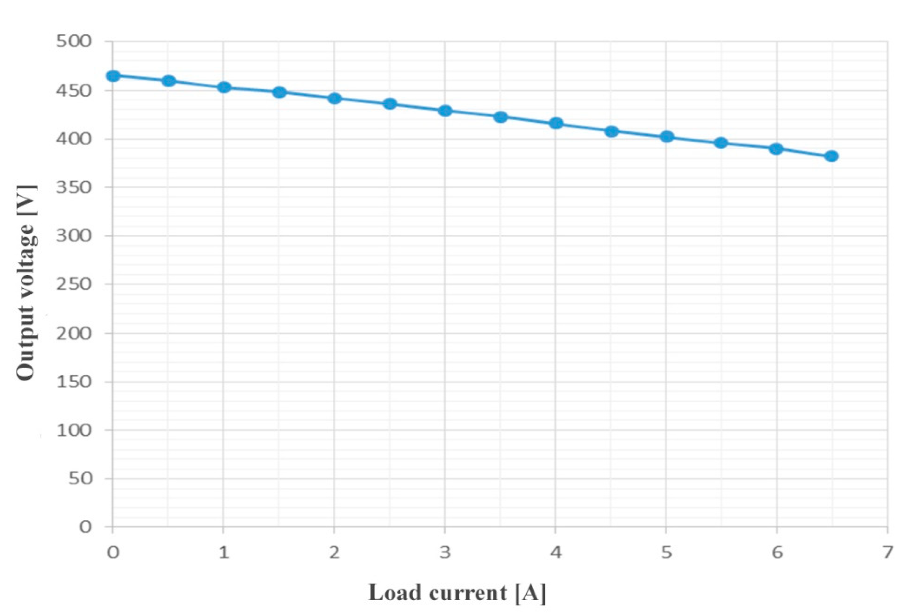
The load characteristics best illustrate the energy characteristics of the generator. During its measurement, the tested generator was resistively loaded, symmetrically in each phase. During this test, a speed of 170 rpm was established and the generator was gradually loaded. The results of measurements are presented in Figure 12.
5. Conclusions
Slow-speed, gearless permanent magnet generators are being used increasingly frequently in small wind electric systems to support the heating systems in single-family houses or to return energy to the grid via appropriate electronic systems. The design presented in this paper has a negligibly small cogging torque less than the values of friction in the bearings and sealing rings. As a result, the turbine will start at very low wind speeds. It also has the advantage of a low rotational speed of 167 rpm, which allows the alternator to be directly coupled to the wind turbine. The tested generator efficiency is at a high level of 83% (the targeted efficiency of 85% was not achieved). The research shows that at rated loads, the copper losses account for 71% of the total generator losses. The efficiency can be increased by increasing the cross-section of the generator winding wire. However, this requires design changes, as the current winding hardly fits into slots of the present cross-section. The sum of the power losses occurring in a generator is the mechanical power delivered (product of speed and shaft torque; torque meter) minus the electrical power received from the generator, i.e., power meters. Power losses in copper are the square of the current times the winding resistance. These losses were determined in tests of a prototype generator. They can be reduced by using a winding with a larger wire cross-section, but this requires an increase in the area of the grooves, which causes an increase in the dimensions of the generator stator. The presented design is light due to its lightweight rotor and aluminium casing. The developed generator can also be used in small hydropower plants that use low-speed water wheels instead of high-speed water turbines. Then, a mechanical gearbox with a single gear ratio can be used, resulting in a higher mechanical efficiency of the entire generator drive system.
Author Contributions
Conceptualization: S.R. and Z.G.; Methodology A.R.; Software, validation: S.R. and Z.G.; formal analysis, investigation, resources: S.R., A.R. and Z.G.; writing—review and editing, S.R.; visualization, A.R.; supervision, Z.G.; project administration, Z.G.; funding acquisition, S.R. All authors have read and agreed to the published version of the manuscript.
Funding
This research received no external funding.
Institutional Review Board Statement
Not applicable.
Informed Consent Statement
Not applicable.
Data Availability Statement
Not applicable.
Conflicts of Interest
The authors declare no conflict of interest.
References
- Kutt, F.; Blecharz, K.; Karkosiński, D. Axial-Flux Permanent-Magnet Dual-Rotor Generator for a Counter-Rotating Wind Turbine. Energies 2020, 13, 2833. [Google Scholar] [CrossRef]
- Degner, M.; Munoz, A.; Liang, F. Evaluation of interior pm and surface pmsynchronous machines with distributed and concentrated windings. In Proceedings of the 2008 34th Annual Conference of IEEE Industrial Electronics (IECON), Orlando, FL, USA, 10–13 November 2008; pp. 1189–1193. [Google Scholar]
- El-Refaie, A.M. Fractional slot concentrated windings synchronous permanentmagnet machines: Opportunities and challenges. IEEE Trans. Ind. Electron. 2010, 57, 107–121. [Google Scholar] [CrossRef]
- Goryca, Z.; Paduszyński, K.; Pakosz, A. Model of the multipolar engine with decreased cogging torque by asymmetrical distribution of the magnets. Open Phys. 2018, 16, 42–45. [Google Scholar] [CrossRef] [Green Version]
- Goryca, Z.; Różowicz, S.; Różowicz, A.; Pakosz, A.; Wachta, H.; Leśko, M. Impact of Selected Methods of Cogging Torque Reduction in Multipolar Permanent-Magnet Machines. Energies 2020, 13, 6108. [Google Scholar] [CrossRef]
- Hwang, S.M.; Eom, J.B.; Hwang, G.B.; Jeong, W.B.; Jung, Y.H. Cogging torque and acoustic noise reduction in permanent magnet motors by teeth pairing. IEEE Trans. Magn. 2000, 36, 3144–3146. [Google Scholar] [CrossRef]
- Ishak, D.; Zhu, Z.Q.; Howe, D. High torque density permanent magnet brushless machines with similar slot and pole numbers. J. Magn. Magn. Mater. 2004, 272–276, 1767–1769. [Google Scholar] [CrossRef]
- Koh, C.S.; Seol, J.S. New cogging torque reduction method for brushless permanent-magnet motors. IEEE Trans. Magn. 2003, 39, 3503–3506. [Google Scholar]
- Libert, F.; Soulard, J. Investigation on pole-slot combinations for permanent magnet machines with concentrated windings. In Proceedings of the International Conference on Electrical Machines (ICEM), Lodz, Poland, 5–8 September 2004. [Google Scholar]
- Paduszyński, K.; Goryca, Z.; Pakosz, A. The influence of asymmetrical distribution of rotor’s magnets on the cogging torque of the multipolar machine. In Proceedings of the 18th International Symposium on Electromagnetic Fields in Mechatronics, Electrical and Electronic Engineering (ISEF), Lodz, Poland, 14–16 September 2017. [Google Scholar]
- Różowicz, S.; Goryca, Z.; Peczkis, G.; Korczak, A. Pico hydro generator as an effective source of renewable energy. Przegląd Elektrotechniczny 2019, 4, 200–204. [Google Scholar] [CrossRef]
- Różowicz, S.; Zawadzki, A.; Włodarczyk, M.; Wachta, H.; Baran, K. Properties of fractional-order magnetic coupling. Energies 2020, 13, 1539. [Google Scholar] [CrossRef] [Green Version]
- Steinbrink, J. Analytical determination of the cogging torque in brushless motor excited by permanent magnets. In Proceedings of the IEEE International Electric Machines & Drives Conference, Antalya, Turkey, 3–5 May 2007; Volume 1, pp. 172–177. [Google Scholar]
- Kostro, G.; Michna, M.; Kutt, F.; Ronkowski, M. Low speed permanent magnet synchronous generator for vertical axis wind turbine. In Proceedings of the International Symposium on Electrical Machines (SME2017), Naleczow, Poland, 18–21 June 2017. [Google Scholar]
- Różowicz, S.; Tofil, S. The influence of impurities on the operation of selected fuel ignition systems in combustion engines. Arch. Electr. Eng. 2016, 65, 349–360. [Google Scholar] [CrossRef] [Green Version]
- Różowicz, S. Use of the mathematical model of the ignition system to analyze the spark discharge, including the destruction of spark plug electrodes. Open Phys. 2018, 16, 57–62. [Google Scholar] [CrossRef] [Green Version]
- Melcescu, L.; Tudorache, T.; Craiu, O.; Popescu, M. Finite element analysis of a wind generator with two counter-rotating rotors. In Proceedings of the 2017 International Conference on Optimization of Electrical and Electronic Equipment (OPTIM) 2017 Intl Aegean Conference on Electrical Machines and Power Electronics (ACEMP), Brasov, Romania, 25–27 May 2017; pp. 408–413. [Google Scholar]
- Eclipse Magnetics. Sintered Neodymium Iron Boron (NdFeB) Magnets. Available online: https://www.eclipsemagnetics.com/site/assets/files/2399/neodymium_grades_data.pdf (accessed on 15 December 2021).
- Xiao, X.; Roh, B.-M.; Zhu, F. Strength Enhancement in Fused Filament Fabrication via the Isotropy Toolpath. Appl. Sci. 2021, 11, 6100. [Google Scholar] [CrossRef]
- Xiao, X.; Joshi, S. Process planning for five-axis support free additive manufacturing. Addit. Manuf. 2020, 36, 101569. [Google Scholar] [CrossRef]
- Xiao, X.; Joshi, S.; Cecil, J. Critical assessment of Shape Retrieval Tools (SRTs). Int. J. Adv. Manuf. Technol. 2021, 116, 3431–3446. [Google Scholar] [CrossRef]
- Xiao, X.; Waddell, C.; Hamilton, C.; Xiao, H. Quality Prediction and Control in Wire Arc Additive Manufacturing via Novel Machine Learning Framework. Micromachines 2022, 13, 137. [Google Scholar] [CrossRef]
Figure 1.
Magnetisation characteristics of steel in different field strength ranges, red points indicate data provided by the manufacturer.
Figure 1.
Magnetisation characteristics of steel in different field strength ranges, red points indicate data provided by the manufacturer.

Figure 2.
Demagnetisation characteristics of the N38H magnet [18].
Figure 2.
Demagnetisation characteristics of the N38H magnet [18].

Figure 3.
Magnetisation characteristics of the M350-50A sheet metal, red points are read from the catalogue, blue line corresponds to extrapolations based on these points.
Figure 3.
Magnetisation characteristics of the M350-50A sheet metal, red points are read from the catalogue, blue line corresponds to extrapolations based on these points.

Figure 4.
Dynamic magnetisation characteristics of the rotor and stator steel.

Figure 5.
Distribution of induction in the magnetic circuit of the generator.

Figure 6.
The induction value in the air gap of the generator in the range of about 180°.

Figure 7.
Generator winding diagram.

Figure 8.
View of the wound stator stack.

Figure 9.
View of the rotor.

Figure 10.
View of the prototype generator.

Figure 11.
Output voltage vs. rotational speed.

Figure 12.
Output voltage vs. load current at 170 rpm.


Table 1.
Rotor steel magnetisation characteristics.
| T | 0.1 | 0.2 | 0.3 | 0.4 | 0.5 | 0.6 | 0.7 | 0.8 | 0.9 |
| A/m at 50 Hz | 36.4 | 48.1 | 56.1 | 63.2 | 70.2 | 77.5 | 85.6 | 94.8 | 106 |
| T | 1.0 | 1.1 | 1.2 | 1.3 | 1.4 | 1.5 | 1.6 | 1.7 | 1.8 |
| A/m at 50 Hz | 122 | 146 | 185 | 264 | 481 | 1200 | 3025 | 6186 | 10720 |
Table 2.
M350-50A sheet metal magnetisation characteristics.
| Bk [T] | 0.1 | 0.2 | 0.3 | 0.4 | 0.5 | 0.6 | 0.7 | 0.8 | 0.9 | 1.0 | 1.1 |
| Hk [A/m] | 76.3 | 147.9 | 218.1 | 290.1 | 367.2 | 452.9 | 550.3 | 660.2 | 781.2 | 918.9 | 1092.1 |
| Bk [T] | 1.2 | 1.3 | 1.4 | 1.5 | 1.6 | 1.7 | 1.8 | 1.9 | 2.0 | 2.1 | 2.2 |
| Hk [A/m] | 1307.5 | 1573.5 | 2000 | 2759.4 | 4000 | 6884.6 | 13,000.3 | 23,939.4 | 41,293.9 | 66,655.9 | 99,960.1 |
Publisher’s Note: MDPI stays neutral with regard to jurisdictional claims in published maps and institutional affiliations. |
© 2022 by the authors. Licensee MDPI, Basel, Switzerland. This article is an open access article distributed under the terms and conditions of the Creative Commons Attribution (CC BY) license (https://creativecommons.org/licenses/by/4.0/).
Share and Cite
MDPI and ACS Style
Różowicz, S.; Goryca, Z.; Różowicz, A. Permanent Magnet Generator for a Gearless Backyard Wind Turbine. Energies 2022, 15, 3826. https://0-doi-org.brum.beds.ac.uk/10.3390/en15103826
AMA Style
Różowicz S, Goryca Z, Różowicz A. Permanent Magnet Generator for a Gearless Backyard Wind Turbine. Energies. 2022; 15(10):3826. https://0-doi-org.brum.beds.ac.uk/10.3390/en15103826
Chicago/Turabian StyleRóżowicz, Sebastian, Zbigniew Goryca, and Antoni Różowicz. 2022. "Permanent Magnet Generator for a Gearless Backyard Wind Turbine" Energies 15, no. 10: 3826. https://0-doi-org.brum.beds.ac.uk/10.3390/en15103826
Note that from the first issue of 2016, this journal uses article numbers instead of page numbers. See further details here.