
Experimental and Numerical Study of the Flammability Limits in a CH4/O2 Torch Ignition System


Chemical Propulsion Laboratory, Department of Aerospace Engineering, University of Brasilia, St. Leste Projeção A-Gama Leste, Brasília 72444-240, Brazil
*
Author to whom correspondence should be addressed.
†
These authors contributed equally to this work.
Energies 2022, 15(11), 3857; https://0-doi-org.brum.beds.ac.uk/10.3390/en15113857
Submission received: 7 April 2022
/
Revised: 25 April 2022
/
Accepted: 4 May 2022
/
Published: 24 May 2022
(This article belongs to the Special Issue Combustion and Propulsion Systems)
Abstract
:The current work is devoted to studying combustion initiation inside the methane-oxygen torch igniter for a hybrid rocket motor. The ignition system can generate a wide range of power and oxidizer-to-fuel ratios. It has a self-cooled vortex combustion chamber with one fuel jet injector and one circumferential vortex oxidizer injector. The system adjusts the mass flow rates of the propellants through the control valves and organizes cooling of the wall and flame stabilization. Experimental analysis of the ignition limits was investigated on the laboratory test bench. The propellants’ pressure and mass-flow rates, combustion temperature, ignition delay, and spark frequency were controlled during the tests. The authors executed a series of tests with different propellants’ mass flow rates. As a result, the region of stable ignition was found as well as the regions of ignition failure or unreliable ignition. A previously validated numerical model was used to analyze the flow in the reliable ignition region and the ignition failures region. Several numerical simulations of the transient three-dimensional chemically reacting flow were implemented. Consequently, the ignition delay and the thermal impact on the combustion chamber wall were determined numerically. Results of the simulations were compared with theoretical and experimental data showing good correspondence.
1. Introduction
The Chemical Propulsion Laboratory (CPL) of the University of Brasilia has designed, manufactured, and tested a simple gas torch ignition system for a hybrid rocket engine and ramjet engines developed at the Laboratory. The ignition system working on the gaseous methane-oxygen mixture can generate a wide range of power and oxidizer-to-fuel ratios, providing favorable conditions for the engines ignition. The igniter has a self-cooled vortex combustion chamber with one fuel jet injector and one circumferential vortex oxidizer injector. Thus, the flow is oxidizer-rich near the wall protecting it from overheating, and fuel-rich in the chamber axis. The current work is devoted to studying combustion initiation inside the igniter from the spark plug discharge mounted on the igniter’s combustion chamber wall.
Several disadvantages are typical for simple pyrotechnic ignition systems used in hybrid propulsion engines. The main one is the absence of re-ignition possibility. In addition, on the laboratory scale, it is preferable to have a controllable, reliable ignition system with simple power regulation, which could be used in different aerospace applications, such as hybrid rocket engines or ramjet engines. Thus, a gas torch ignition system could be a good option for motor initiation because of its relative simplicity and reliability [1,2]. A torch ignition is also controllable when compared to pyrotechnic igniters.
The current work is devoted to the experimental study of methane-oxygen flammability at various mixture ratios. According to [3], a methane-oxygen pure mixture is flammable in a wide range of concentrations; however, a stable ignition could exist only when a methane concentration lies between 5% and 60% by volume. Another critical parameter involved in the ignition process is the spark energy required for reliable flame initiation. Zabetakis [3] defined it as the “ignitibility limit”; it is near 1 mJ for the GOX/GCH mixture.
Analysis of the recent publications allowed to qualify and quantify the combustion properties of methane-oxygen flames and estimate parameters that impact flammability and stability of the flame. Analytical estimation of the flame structure for the current work is based on the work of Melvin and Moss [4], where the properties of methane-oxygen diffusion flames are given in a precise mathematical and physical model allowing to make a critical comparison between different reaction schemes and elaborate analytical prediction of the mixture composition during the methane-oxygen combustion process. Previously Bae et al. [5] have found the stability limits of the oxygen-methane diffusion flame using the jet and vortex injectors combination. A compact size injector model was elaborated and showed a dependence of the visible flame length from the Reynolds number between and O/F ratio between 19.8…32.8. Another definition of methane-oxygen flame stability is given by Moore et al. [6], allowing to determine its relation to Reynolds number and O/F ratio. As shown in [6], validated operating conditions of these dimensionless criteria are very close to the current study, predicting the limits of regimes of the reliable ignition process and constraints on anchored, detached flames and near-blowoff flames with very large amplitudes of oscillations.
In [7], Ellis describes a background of a LOX/CH swirl torch ignition system for the main rocket engine and shows flammability maps for various combinations of propellants.
Pauly et al. [8] show conditions of the flame attachment to the injector when applied to coaxial jets, flame stabilization in time, and its liftoff distance during the flame stabilization.
The ignition characteristics of a small thrust rocket engine working on a methane-oxygen mixture were described by Jia-qi et al. [9]; the injectors’ configuration was determined to achieve a stable motor ignition. It was confirmed that a spark plug directly connected to the rocket engine’s combustion chamber is not capable of supplying enough energy for ignition. In this context, building a compact stand-alone torch igniter becomes an essential key technology for the reliable ignition of a rocket motor.
According to Li [10], swirling combustion of pure methane-oxygen diffusion flames similar to the current work is characterized by a stable tubular flame for the when outside of this limit, a flame would be oscillating or unsteady.
Development of the torch ignition system for upper stage engine Vinci was described by Frenken and Vermeulen [11]. The system components were described, and the system operation’s main parameters were discussed. It was shown that a compact gas torch igniter of 440 kW of thermal power could lead to a reliable operation when its design and flow conditions are optimized.
Kinetic mechanisms for modern CFD tools of methane-oxygen mixture combustion were studied by Haidn et al. [12] to estimate a design approach for effective injectors geometry and flow conditions for startup combustion sequence and critical requirements for the feasible ignition system. Moon et al. [13] realized an experimental study on a methodology for reliability estimation of a pyrotechnic ignition system for a hybrid rocket motor, which could be extended to a gas torch ignition system discussed in the current work.
The main design problem of the gas torch ignition system is the requirement to provide high relative power to a rocket motor with small and compact dimensions of the igniter. In these conditions, the flow velocity inside the igniter is always high, flammable conditions are forming too far from the spark discharge, the energy of the spark is being dissipated in the cold flow of the oxidizer, and there is no chance of igniting the mixture. Experimental tests provided in the Laboratory [2] entirely discovered this problem. Therefore, flow conditions favorable for ignition must be created inside the igniter, which is generally characterized by a slow flow velocity close to the flame velocity for methane-oxygen mixtures, previously discussed in [2,14,15].
One possible solution to have a reliable ignition process inside the igniter is to establish an ignition program to guarantee a flammable mixture near the spark plug at the moment of the spark generation.
The main objective of the current work is to find experimentally the flow parameters corresponding to a reliable ignition process of the vortex combustion chamber which are determined by a particular value of the fluxes and concentrations near the spark plug, satisfying the flammability limits and the flame speed in the ignition point. The following steps were taken in order to reach this objective:
- -
- analytical and numerical investigation on the ignition limits of methane-oxygen mixtures;
- -
- the creation of the control algorithm for precise mass flow rate quantification in the ignition system;
- -
- the building of the test bench, plan of tests, methodology of the experimental search of ignition limits.
2. Material and Methods
The current study involves experimental and numerical methods to search for the combinations of propellants fluxes that would create favorable conditions (O/F ratio) for a flame appearance near the spark providing ignition energy and also providing a flow velocity (Re) which would be advantageous for the flame propagation and stabilization inside the combustion chamber. To reach this goal, the following methods were used:
- -
- Experimental research on ignition limits provided by CPL for gas torch ignition system working on GOX/GCH mixture in a wide range of possible O/F ratios and Reynolds numbers. The test bench for this experiment was built at the CPL test facility;
- -
3. Experimental Setup
3.1. Ignition System
The ignition system is shown in Appendix A, in Figure A1 and was described in [16]. It consists of propellants tanks, supply lines, pressure control valves, safety valves, sensors, control hardware, and software, and the ignition device is further called an “igniter”.
Flow comes from high-pressure methane and oxygen tanks and passes through the pressure regulation valves. After that, propellants pass through the high-precision digital control valves, creating appropriate flow conditions inside the igniter where combustion happens. There are also stop-valves on the inlet of igniter preventing back-flow of propellants. Flow is controlled by the pressure sensors on the methane and oxygen lines and a thermocouple installed inside the igniter.
3.2. Igniter
The igniter structure is shown in Figure 1. Methane flow coming through inlet 1 and oxygen through inlet 2 and passing through the oxygen swirl injector 3 and conical jet injector 4, respectively, form a vortex of the combustible mixture inside the igniter’s combustion chamber 7 of 1 inch diameter. When the mixture is ignited by the spark plug 5, a temperature rise could be detected by the thermocouple 6. A spark with a discharge energy of 60 mJ was chosen for the means of the current research project that mitigates any dependence on ignitibility limits problem discussed earlier.
Once the flame is detected, the ignition system increases the propellants’ mass flow rates providing necessary energy output to the rocket motor during the ignition sequence. Convergent nozzle 8 constrains velocity inside the igniter’s combustion chamber and guarantees flame stabilization inside a vortex combustion chamber.
A cold swirling flow of oxygen passes near the combustion chamber wall, effectively protecting it from the high temperature of the flame, which could reach up to 3030 K for the stoichiometric mixture at 1 atm, according to [14]. A gas mixture exiting the igniter is always oxidizer-rich, which helps, on the one hand, to cool down effectively the igniter wall, and on the other hand, to initiate combustion inside a solid fuel ramjet [17] or hybrid rocket engine [18] with solid fuel grain of paraffin or high-density polyethylene tested in the Laboratory. A thermocouple position in the current work was set near the combustion chamber wall to estimate a thermal loads peak at the ignition moment and reduce a cooling vortex disturbance.
As it follows from the references [1,3,4,5,6], and others, the build-up of the ignition sequence is an essential condition to the construction of a reliable and predictable ignition system.
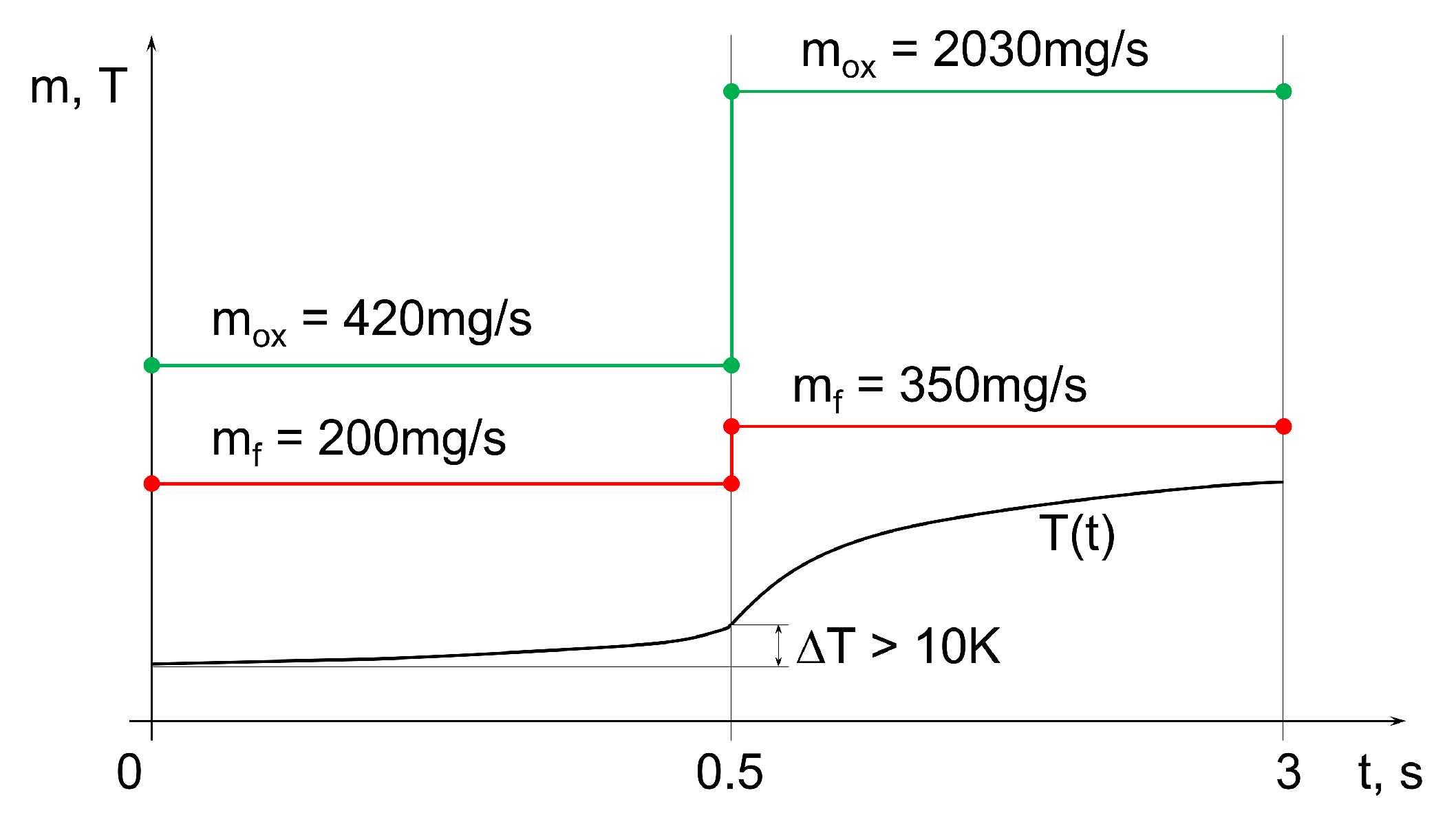
The authors propose to use a 2-step ignition sequence (Figure 2) in the current work. Figure 2a shows the initiation of the combustion process characterized by relatively low velocity and pressure. It creates a flammable mixture in a zone of spark plug and at the same time having high enough speed to keep the flame inside a combustion chamber, described in [6], and (Figure 2b)—full power output allowing ignition of the rocket motor and satisfying self-cooling stable operation of the system previously described in [2,16].
A transition between these regimes happens through the thermal flow control by thermocouple 6 (Figure 1). The experimental testing showed that a reliable temperature difference for ignition detection is 10 K, which is one order higher than a possible noise in the temperature acquisition channel. Regimes 1 and 2 (Figure 2a,b) were implemented by a homemade algorithm, controlling hardware based on the National Instruments CompactDAQ system.
3.3. Test Bench Assembly
An assembly of the system was provided in two different locations. A propulsion component of the ignition system was installed on the test stand of the CPL in the propulsion room, and the control system and processing computers were placed inside the control room for safety reasons. Observation of the system operation was realized through video cameras and DAQ channels. The ignition system was mounted with the combustion chamber (Figure 3) of a SARA hybrid motor [18]. An assembly of the ignition system with an engine ensures its operation according to the SARA motor design conditions. The combustion chamber was fixed on a moving cart by clamps, and the igniter was connected to the axial port.
Stainless-steel flexible hoses for propellants are designed to sustain high pressure up to 200 bar to prevent system destruction due to possible pressure oscillations during hybrid motor operations. The possibility of a back-flow is controlled by stop valves installed before these hoses (not shown in Figure 3) at a distance of 500 mm from the igniter. K-type 12 inch thermocouple is assembled through the adapter allowing the possibility of simultaneous pressure measurement inside the igniter’s combustion chamber when required. A compact spark-plug NGK CM-6 provides 60 mJ during 4.16 ms per spark with a frequency of 30 Hz, which is sufficient for reliable system ignition.
Flow control proportional valves are actuated through high-torque Hitec servomotors by a PWM signal generator from the DAQ system. The resolution of a control signal is 32-bit which gives around 100 levels between completely closed position and fully opened () position, allowing a precise dosage injection of the propellants inside the igniter’s combustion chamber.
3.4. Mass Flow Rate Estimation
A mass flow rate of propellants for the ignition system was found experimentally and approximated by an empirical function (1) of a static flow pressure and valve opening level. It was studied by Santos [19] and could be expressed as:
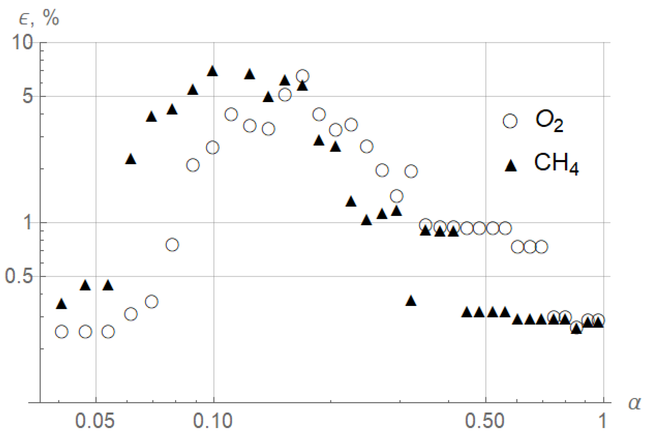
A water displacement method [16] was used to quantify the propellant’s mass flow rate (Figure 4), which was found to be adequate and quite precise (Figure 5) for a low gas volume. Flow values less than 1 mg/s are not shown. A flow was assumed adiabatic and compressible.
The total error of mass flow measurement took into account time delays of system response, positioning of the control valves, sensor error, and signal noise. It was found that total associated error is strictly related to valve opening levels and is practically independent of the propellants’ inlet pressure. Here (Figure 5), the deviation is relative to the mass flow rate of propellants at the corresponding valve opening level; it is elevated for small values of because of a high gradient of function (1) for (0, 0.3) according to [16].
Quantification of the propellants mass flow rate was made by reverse function to (1), defining the valve opening level as a function (2) of the required mass flow rate and line static pressure:
Function (2) is implemented in a valves control software. Knowing the functions (1) and (2), it becomes possible to define the flow average O/F ratio values from the empirical function as
Combining the definition of a total mass flow rate with Equation (1)
we may see that the O/F ratio may be expressed by a total mass flow rate and methane mass flow rate functions:
In the same way, for the case when the O/F ratio and total mass flow rate are the controlling parameters, the valve opening levels could be defined as
which allows characterizing a flow by O/F ratio and the total mass flow rate. Assuming adiabatic flow inside the injectors before combustion starts, function (6) could also be defined by dimensionless criteria
Function (7) follows a theory of Moore [6] when the ignition occurrence is based on dimensionless parameters, and the Reynolds number is defined by methane jet properties as . Relations (1)–(7) were found experimentally and approximated as continuous empirical functions in control software.
During the experimental tests, GOX mass flow rate variation will range from 7 to 1260 mg/s and of GCH from 2 to 360 mg/s. These intervals will be divided into 10 discrete values (Table 1), totaling 100 possible combinations of propellants’ mass flow rates.
Using relation (2), it will be possible to control valve opening levels according to desired flows of propellants. For every combination of propellants, at least 4 ignition attempts will be performed, and approximate ignition probability will be determined. After mapping all the results, a conclusion about the optimal propellants mass flows will be made.
3.5. Numerical Experiment
The current work’s numerical model is based on the Naiver-Stokes equation system averaged by Favre for the turbulent three-dimensional flows, given in [20] approximated by Ahmed [21] and implemented in ANSYS Fluent 19.0. The flow of the propellants mixture is simulated by a continuity equation applied to each specie in the mixture. The chemical kinetics of the reacting flow is solved by the Frassoldati scheme [22], which is an adaptation of the Jones-Lindstedt mechanism [23]. Thermodynamic properties of the mixture and transport coefficients were calculated by the Gri-Mech 3.0 library [24]. The RNG turbulence model with the eddy-dissipation concept is indicated for rotational chemically reacting turbulent flows used in the current work. Average values of 10 were observed during simulations, which justifies wall-scalable functions [25].
A SIMPLEC algorithm realized Pressure-velocity coupling from Vandoormaal and Raithby [26] applied to pressure-based flows. Approximation of the model in space coordinate was implemented by the second-order PRESTO scheme [27]. The second-order upwind scheme approximated time derivative. Boundary conditions were set according to Table 2, mass flow inlet values were used for propellants, static pressure definition for flow exiting the nozzle, slipping and adiabatic conditions were defined on the wall.
Five flow “cases” (Table 2) correspond to points of interest for ignition process validation.
The unstructured tetrahedral mesh was built inside the simulation volume with refinement near the walls to satisfy y conditions, on the central jet of igniter to resolve the flame structure, and near a spark plug to improve the accuracy for transient ignition process simulation. Mesh sensitivity analysis was performed by Sousa [2] to optimize the accuracy, simulation time, and flow convergence process. Various criteria were used for mesh sensitivity analysis, such as temperature, pressure, velocity, mass fractions of species distributions on the axial and radial directions of the igniter, and the surface integrals on a thermocouple wall. A mesh of 2,226,473 effectively distributed cells was considered optimal after the analysis; an increase in the number of elements to 3,901,468 resulted in less than 5% of the species concentrations’ relative change inconsiderably slight deviation of the other flow properties.
Numerical representation of the spark ignition mechanism was realized according to Kawahara et al. [28]; local temperature between electrodes increased up to 2289.9 K by a patch function during the spark exposure of 4.16 ms.
The two-step flow simulation was implemented in the current work. In the first step, the stationary cold flow was established according to initial conditions from Table 1. In the second step, a spark discharge in a transient regime was simulated, showing flame structure evolution in time until flame stabilization occurred.
4. Results and Discussion
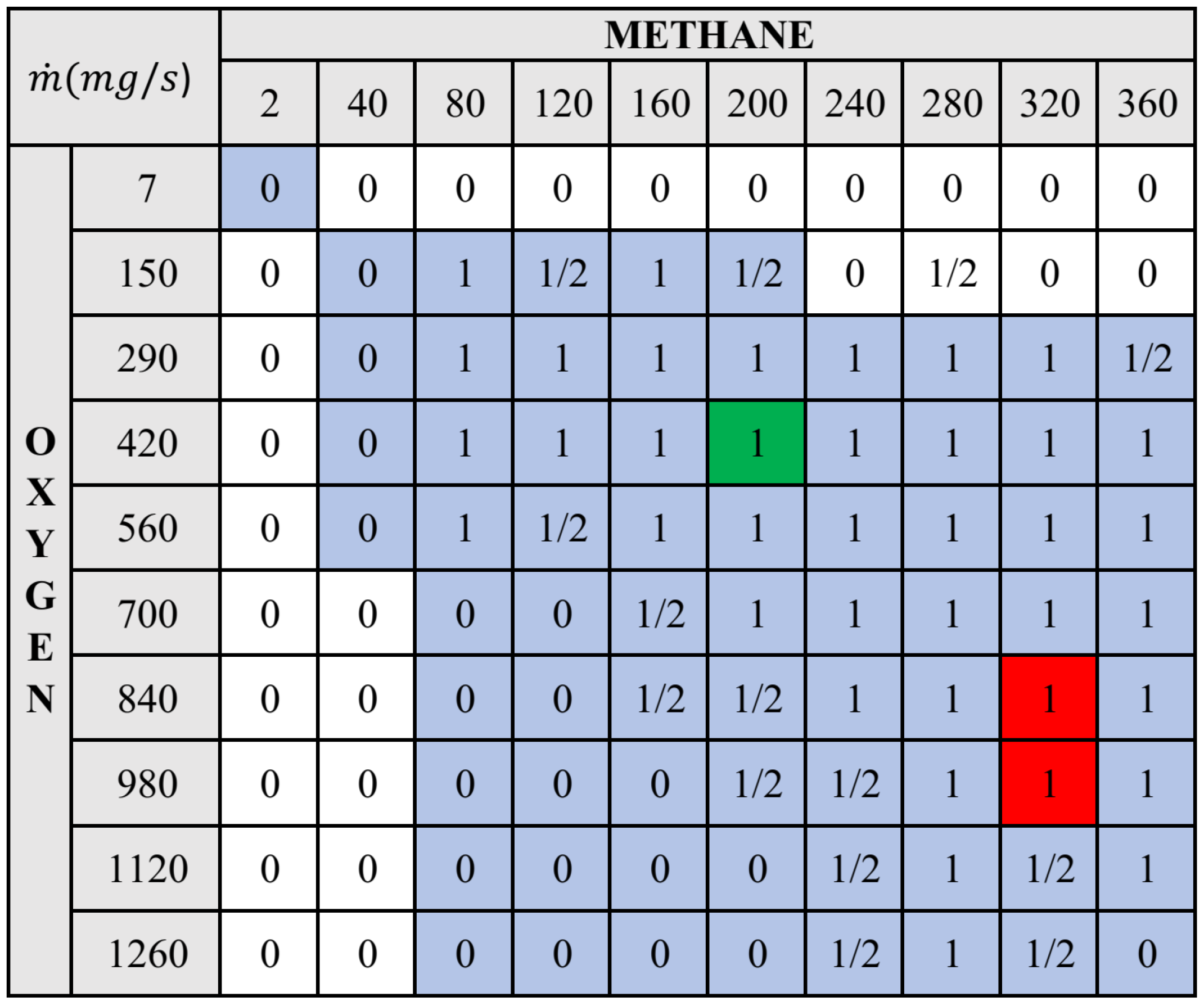
Experimental results on ignition attempts are presented in Figure 6 in terms of propellants’ mass flow rates. At least four ignition attempts were performed for each combination of propellants, more than 400 test tries in total. Here (Figure 6), values represent the “ignition probability”: value 0 indicates that no ignition was observed during all the ignition attempts, 1/2—at least two ignitions occurred in 4 tries, and 1—ignition occurred in all endeavors.
Blue-colored cells correspond to the average mixture ratio defined as flammable, according to Zabetakis [3]. Red-colored cells correspond to the destruction of the thermocouple (Figure 1, item 6) due to unfavorable extra-elevated flame temperatures in the measurement region. The existence of the “red cells” could be found experimentally or numerically. However, it could not be detected by analytical methods. Green-colored cells (Figure 6) corresponded to the optimal propellant mixture ratio when ignition happened for all attempts. In addition, it is important to note that the optimal ignition cell is surrounded by successful ignition cells, so a 10% variation of propellants concentrations will still lead to a successful ignition process. Since the error of the flow control valves estimated previously (Figure 5) is smaller, the flow control system will always guarantee a good mixture for a successful ignition.
An additional experimental investigation on the optimal ignition region was provided for a sequence of 100 ignition attempts where no failures were observed, proving a concept of the choice of the optimal ignition point. Estimated ignition probability is definitively higher than 99% for every ignition attempt. Detailed investigation of the ignition probability could be performed in the future, particularly by adopting the methodology proposed in [13].
As seen from Figure 6, theoretical flammability limits shown as the “blue cells” are shifted concerning experimentally confirmed ignition. In our opinion, it happens because vortex injection makes swirling oxygen concentrate near the wall, and lighter methane stays near the flow axis, preventing an appearance of a flammable mixture in the sparking region.
The optimal rocket engine ignition sequence elaborated in the current work is presented in Figure 7. The flow of GOX and GCH for combustion initiation is respectively 420 and 200 mg/s.
After approximately 0.5 s, ignition will be detected, and mass flow rates will be increased up to 2030 and 350 mg/s, respectively, providing near 17.5 kW of thermal power during 3 s to the combustion chamber of the hybrid rocket engine or ramjet for its complete ignition [16,17].
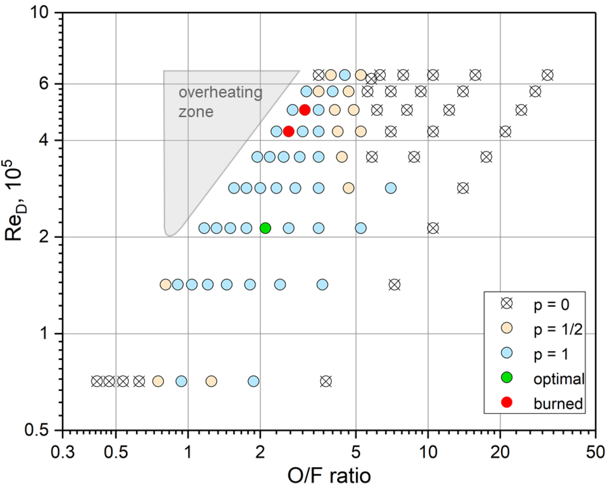
Dimensional analysis of the ignition limits inside the combustion chamber was implemented to experimentally determine ignition probability in terms of Reynolds number and oxidizer to fuel ratio. It may be noticed (Figure 8) some similarities of O/F ratios and when compared to work [6]; however, the ignition limits were shifted to higher Reynolds values concerning a jet flow for the swirling flow. Experimentally found optimal and stable ignition regime corresponding to O/F = 2.1 and = 21,320.
As may be seen from the experimental data, the ignition failure could be observed at O/F ∈ (0.8, 5) and in most cases. These limits, especially an ignition map (Figure 8), would allow scaling a vortex combustion chamber for the igniter’s different required output power levels.
A zone of igniter wall overheating is typical for low and near-stoichiometric O/F ratios; it is an undesirable combustion starting point, where the flow of oxygen protection layer is absent, and the flame is attached to the wall.
A transient numerical study of optimal ignition case 1 (Table 2) showed that ignitable mixture conditions were formed after 6 ms, and flame development inside the combustion chamber started (Figure 9). At 15 ms, the flow reaches a fuel injector, and at 21 ms, a flame begins to form a central vortex shape. From 27 ms to 47 ms, a flame jet attaches to a nozzle wall, which expresses short elevated thermal loads; this effect must be additionally considered when choosing a nozzle material.
A detached flame in quasi-stationary flow was formed after approximately 200 ms, the thermocouple position for ignition detection in the future could be placed inside the isothermal surface (Figure 9). As already explained, the thermocouple was placed on the wall to have a “pure” undisturbed cooling vortex; the ignition occurrence was detected by a sound of a shock wave formed at the ignition moment.
Numerical simulations performed for flow cases from 1 to 5 (Table 2) showed numerical stability and convergence and allowed to detection of equivalence ratios at the spark discharge region.
Ignition of case 3 commonly occurred because of a favorable mixture close to a spark region. Correspondence between experimentally and numerically detected ignitions inside the vortex combustion chamber (Table 3) proves the numerical approach’s validity in detecting the mixture ignition, but not limited just by the ignition occurrence event.
As may be seen (Figure 10), a flammable mixture according to [3] could be achieved for cases 1 and 3, whereas cases 2 and 5 did not represent favorable ignition flow properties. Further, the ignition of case 4 was possible only when the spark power was increased up to 100 mJ. This case could not represent a reliable ignition because the current energy discharge is much smaller (60 mJ).
An additional study on pressure, temperature, velocity, species concentrations, and mass flow rates validations [1,2,16,17] by the numerical and experimental approaches allowed to reach more complete understanding of the physical processes of the flame formation and propagation inside a compact vortex combustion chamber.
5. Conclusions
Theoretical research on methane-oxygen flammability inside the vortex combustion chamber of the igniter allowed us to estimate favorable ignition conditions, to define the corresponding propellants’ mass flow rates and equivalence ratios for developed ignition devices. This study is fundamental to reaching a reliable, controllable, and repeatable ignition process inside the combustion chamber of a rocket motor or ramjet. The main results could be summarized as follows:
- -
- A wide range of the input flow conditions (mass flow rates, O/F ratios, and Re numbers) was tested experimentally, from which was chosen an optimal ignition regime of the mass flow rates = 420 mg/s, = 200 mg/s that corresponds to dimensionless flow parameters O/F = 2.1 and = 21,320.
- -
- Ignition limits for a methane-oxygen flow mixture inside the vortex combustion chamber were found.
- -
- Regions of structure overheating and thermocouple failure were mapped.
- -
- An efficient numerical model was built and validated, allowing to study a flame initiation process numerically inside the vortex combustion chamber.
Future works on the system could be devoted to an experimental investigation of combustion stability, efficiency, and scalable operation to satisfy a more expansive range of output ignition power.
Author Contributions
Conceptualization, O.S.; methodology, O.S., D.S., J.L. and A.E.M.B.; software, O.S.; validation, O.S. and D.S.; formal analysis, O.S. and D.S.; investigation, O.S., D.S., J.L. and A.E.M.B.; resources, O.S.; data curation, O.S. and D.S.; writing—original draft preparation, O.S.; writing—review and editing, O.S. and D.S.; visualization, O.S. and D.S.; supervision, O.S.; project administration, O.S.; funding acquisition, O.S. All authors have read and agreed to the published version of the manuscript.
Funding
This research was funded by the Foundation for the Scientific Research Support of the Federal District (FAPDF), Brazil, grant No.0193.001001/2015, 00193-00000229/2021.
Institutional Review Board Statement
Not applicable.
Informed Consent Statement
Not applicable.
Data Availability Statement
The data presented in this study are available on reasonable request from the corresponding author. The data are not publicly available due to the restrictions of the funding institution on going research activities.
Acknowledgments
The authors are grateful for the technical support of collaborators of the Chemical Propulsion Laboratory of the University of Brasilia.
Conflicts of Interest
The authors declare no conflict of interest.
Abbreviations
The following abbreviations are used in this manuscript:
| CPL | Chemical Propulsion Laboratory |
| LOX | Liquid Oxygen |
| GCH | Gaseous Methane |
| GOX | Gaseous Oxygen |
| UnB | University of Brasilia |
| Nomenclature | |
| mass flow rate, g/s | |
| oxidizer-to-fuel ratio, - | |
| p | pressure, bar |
| t | time, s |
| T | temperature, °C |
| W | power, W |
| valve opening level, - | |
| mass flow rate error, % | |
| equivalence ratio, - | |
| Reynolds number, - | |
| Subscripts | |
| 0 | stagnation property |
| f | fuel |
| oxidizer | |
| D | diameter |
Appendix A
The feeding system shown in Figure A1 is composed of two high-pressure tanks filled with oxygen and methane. Each flow, passing through a pressure regulator valve (2), reduces its pressure; then, downstream of a flow valve (3) controlled by the ignition algorithm, a non-return spring-loaded check valve (5) is preventing backflow phenomena. Finally, both flows are injected into the combustion chamber through the injectors and ignited by a spark plug (6) through the spark generator (SG).
The pressure sensors (4) along the feeding lines and inside the combustion chamber are used to determine the mass flow rate of the propellants; moreover, a thermocouple installed inside the combustion chamber reads the temperature. These data, sent to the 14-bit A/D converter of DAQ, are processed by using a control algorithm developed in the CPL and written using the G-Language of the LabVIEW environment.
The pressure transducers have been installed using T-adapters of the same diameter of pipes to avoid losses, thus allowing a more precise measure of the static pressure in the system. They can be positioned, if required, upstream of the flow valves (3) to estimate the pressure drop and flow coefficients inside the valve. Finally, the thermocouple installed inside the combustion chamber is connected to an adjustable adapter, allowing measurements along the chamber diameter; the adapter connection is also compatible with the pressure transducer (7).
Figure A1.
Ignition system schematics.

References
- Souza, K.; Shynkarenko, O. Development of a measurement system of temperature and pressure in the combustion chamber of a torch ignition system. In Proceedings of the 24th International Congress of Mechanical Engineering, Curitiba, Brazil, 3–8 December 2017. [Google Scholar]
- Souza, K. Analysis of the Transient Combustion Process in the Igniter Type Torch. Bachelor’s Thesis, University of Brasilia, Brasília, Brazil, 2017. [Google Scholar]
- Zabetakis, M. Flammability Characteristics of Combustible Gases and Vapors; U.S. Department of the Interior, Bureau of Mines: Washington, DC, USA, 1965; pp. 9–47.
- Melvin, A.; Moss, J. Structure in methane-oxygen diffusion flames. Symp. (Int.) Combust. 1975, 15, 625–636. [Google Scholar] [CrossRef]
- Bae, S.H.; Hong, J.D.; Kim, H.D.; Kim, J.S. Combustion characteristics of methane-oxygen diffusion flame formed by swirl-coaxial injector. J. Korean Soc. Propuls. Eng. 2017, 21, 1–8. [Google Scholar] [CrossRef] [Green Version]
- Moore, J.D.; Risha, G.A.; Kuo, K.K.; Zhang, B.; Wehrman, R.B. Stability of methane/oxygen coaxial diffusion flame. In Proceedings of the 39th AIAA/ASME/SAE/ASEE Joint Propulsion Conference and Exhibit, Huntsville, AL, USA, 20–23 July 2003. [Google Scholar]
- Ellis, R.J. Evaluation of a Torch Ignition System for Propulsion. Master’s Thesis, The University of Texas at El Paso, El Paso, TX, USA, 2014. [Google Scholar]
- Pauly, C.; Sender, J.; Oschwald, M. Ignition of a Gaseous Methane/Oxygen Coaxial Jet. Prog. Propuls. Phys. 2009, 1, 154–170. [Google Scholar] [CrossRef] [Green Version]
- Jiaq, Z.; Qing-Lian, L.; Chi-bing, S. Ignition characteristics and combustion performances of a LO2/GCH4 small thrust rocket engine. J. Cent. South Univ. 2018, 25, 646–652. [Google Scholar] [CrossRef]
- Li, B.; Shi, B.; Zhao, X.; Ma, K.; Dingjiang, X.; Zhao, D.; Li, J. Oxy-fuel combustion of methane in a swirl tubular flame burner under various oxygen contents: Operation limits and combustion instability. Exp. Therm. Fluid Sci. 2017, 90, 115–124. [Google Scholar] [CrossRef]
- Frenken, G.; Vermeulen, E.; Bouquet, F.; Sanders, B. Development Status of the Ignition System for Vinci. In Proceedings of the 38th AIAA/ASME/SAE/ ASEE Joint Propulsion Conference & Exhibit, Indianapolis, IN, USA, 7–10 July 2002. [Google Scholar] [CrossRef]
- Haidn, O.; Celano, M.P.; Meng, L.; Christof, R.; Silvestri, S.; Slavinskaya, N. On Methane/Oxygen Combustion for Rocket Applications. In Proceedings of the International Symposium on Innovation and Prospects of Liquid Propulsion Technology, Xi’an, China, 4–6 September 2016. [Google Scholar]
- Moon, K.H.; Moon, H.; Joo-Ho, C.; Jin-Kon, K. Reliability Prediction of Hybrid Rocket Ignition System. J. Korean Soc. Aviat. Aeronaut. 2016, 24, 26–34. [Google Scholar] [CrossRef] [Green Version]
- Glassman, I.; Yetter, R.A. Flame Phenomena in Premixed Combustible Gases. In Combustion, 4th ed.; Elsevier: San Diego, CA, USA, 2008; pp. 147–260. [Google Scholar]
- Filho, J.A.C.; Simone, D.; Shynkarenko, O. Numerical Study of the Cooling Effect Inside a CH4/O2 Torch Ignition System for Hybrid RM. In Proceedings of the 1st Brazilian Aerospace Congress, Foz do Iguaçu, Brazil, 1–3 November 2018. [Google Scholar]
- Junior, L.O. Experimental and Theoretical Analysis of a Torch Ignition System Based on CH4/O2 Combustion. Bachelor’s Thesis, University of Brasilia, Brasilia, Brazil, 2018. [Google Scholar]
- Moreira, I.P. Conceptual Design of an Air-to-Air Missile with Solid Paraffin Ramjet. Master’s Thesis, University of Brasilia, Brasilia, Brazil, 2018. [Google Scholar]
- Shynkarenko, O.; Andrianov, A.; Bertoldi, A.E.M. Low-thrust hybrid motor efficiency research for design optimization purposes. In Proceedings of the 51st AIAA/SAE/ASEE Joint Propulsion Conference, Orlando, FL, USA, 27–29 July 2015. [Google Scholar]
- Santos, G.F. Numerical Control Valve Simulation for Chemical Propulsion Systems. Bachelor’s Thesis, University of Brasilia, Brasilia, Brazil, 2018. [Google Scholar]
- Chen, C.; Riley, J.J.; McMurtry, P.A. A study of Favre averaging in turbulent flows with chemical reaction. Combust. Flame 1991, 87, 257–277. [Google Scholar] [CrossRef]
- Ahmed, G.; Abdelkader, A.; Bounif, A.; Gökalp, I. Reduced chemical kinetic mechanisms: Simulation of turbulent non-premixed CH4-Air flame. Jordan J. Mech. Ind. Eng. 2014, 8, 66–74. [Google Scholar]
- Frassoldati, A.; Cuoci, A.; Faravelli, T.; Ranzi, E.; Candusso, C.; Tolazzi, D. Simplified kinetic schemes for oxy-fuel combustion. In Proceedings of the 1st International Conference on Sustainable Fossil Fuels for Future Energy—S4FE, Rome, Italy, 6–10 July 2009. [Google Scholar]
- Ranzi, E.; Frassoldati, A.; Granata, S.; Faravelli, T. Wide-Range Kinetic Modeling Study of the Pyrolysis, Partial Oxidation, and Combustion of Heavy n-Alkanes. Ind. Eng. Chem. Res. 2005, 44, 5170–5183. [Google Scholar] [CrossRef]
- Smith, G.P.; Golden, D.M.; Frenklach, M.; Moriarty, N.W.; Eiteneer, B.; Goldenberg, M.; Bowman, C.T.; Hanson, R.K.; Song, S.; Gardiner, W.C., Jr.; et al. GRI Mech 3.0. Available online: http://combustion.berkeley.edu/gri-mech/version30/text30.html (accessed on 1 April 2022).
- Salim, S.M.; Cheah, S.C. Wall y+ strategy for dealing with wall-bounded turbulent flows. In Proceedings of the International MultiConference of Engineers and Computer Scientists, Hong Kong, China, 21–23 October 2020. [Google Scholar]
- Vandoormaal, J.P.; Raithby, G.D. Enhancements of the SIMPLE Method for Predicting Incompressible Fluid Flows. Numer. Heat Transfer 1984, 7, 147–163. [Google Scholar]
- Grasso, F.; Meola, C. Euler and Navier-Stokes Equations for Compressible Flows: Finite-Volume Methods. In Handbook of Computational Fluid Mechanics; Peyret, R., Ed.; Academic Press Limited: Baltimore, MD, USA, 1996. [Google Scholar]
- Kawahara, N.; Hashimoto, S.; Tomita, E. Plasma temperature of spark discharge in a spark-ignition engine using a time series of spectra measurements. In Proceedings of the 18th International Symposium on the Application of Laser and Imaging Techniques to Fluid Mechanics, Lisbon, Portugal, 4–7 July 2016. [Google Scholar]
Figure 1.
The igniter assembly: 1—methane inlet, 2—oxygen inlet, 3—oxygen swirl injector, 4—conical jet injector, 5—spark plug, 6—thermocouple, 7—combustion chamber, 8—nozzle.
Figure 1.
The igniter assembly: 1—methane inlet, 2—oxygen inlet, 3—oxygen swirl injector, 4—conical jet injector, 5—spark plug, 6—thermocouple, 7—combustion chamber, 8—nozzle.

Figure 2.
Ignition regimes: (a) Combustion initiation. (b) Full power flow.

Figure 3.
Igniter mounted on the test bench.

Figure 4.
Mass flow rate measurements in terms of the valve opening level.

Figure 5.
Mass flow rate error.

Figure 6.
Occurrence of ignition inside the igniter’s combustion chamber with in terms of the propellants mass flow rates.
Figure 6.
Occurrence of ignition inside the igniter’s combustion chamber with in terms of the propellants mass flow rates.

Figure 7.
Ignition sequence optimal parameters.

Figure 8.
Ignition limits of the swirling oxygen-methane flow in terms of O/F ratio and methane jet Reynolds number.
Figure 8.
Ignition limits of the swirling oxygen-methane flow in terms of O/F ratio and methane jet Reynolds number.

Figure 9.
Temperature distribution during successful ignition process, case 1.

Figure 10.
Average equivalence ratio in spark region.


Table 1.
Average mass flow rate values to test, in mg/s.
| GOX | 7 | 150 | 290 | 420 | 560 | 700 | 840 | 980 | 1120 | 1260 |
| GCH | 2 | 40 | 80 | 120 | 160 | 200 | 240 | 280 | 320 | 360 |
| 0.04 | 0.71 | 1.42 | 2.13 | 2.84 | 3.55 | 4.26 | 4.97 | 5.69 | 6.40 |
Table 2.
Simulation boundary conditions.
| Bound | Condition | Value | , K | Species |
|---|---|---|---|---|
| Methane inlet | Mass flow, mg/s | 297 | 1.0 [CH] | |
| Oxygen inlet | Mass flow, mg/s | 297 | 1.0 [O] | |
| Nozzle exit | Static pressure | 1 bar | 300 | 0.79 [N] |
| 0.21 [O] | ||||
| Wall | Velocity | V = 0 | ||
| Heat flux |
Table 3.
Comparison of experimental and numerical results.
| Case no. | Experimental Ignition | Numerical Ignition |
|---|---|---|
| 1 | yes | yes |
| 2 | no | no |
| 3 | yes | yes |
| 4 | sometimes | possible |
| 5 | no | no |
Publisher’s Note: MDPI stays neutral with regard to jurisdictional claims in published maps and institutional affiliations. |
© 2022 by the authors. Licensee MDPI, Basel, Switzerland. This article is an open access article distributed under the terms and conditions of the Creative Commons Attribution (CC BY) license (https://creativecommons.org/licenses/by/4.0/).
Share and Cite
MDPI and ACS Style
Shynkarenko, O.; Simone, D.; Lee, J.; Bertoldi, A.E.M. Experimental and Numerical Study of the Flammability Limits in a CH4/O2 Torch Ignition System. Energies 2022, 15, 3857. https://0-doi-org.brum.beds.ac.uk/10.3390/en15113857
AMA Style
Shynkarenko O, Simone D, Lee J, Bertoldi AEM. Experimental and Numerical Study of the Flammability Limits in a CH4/O2 Torch Ignition System. Energies. 2022; 15(11):3857. https://0-doi-org.brum.beds.ac.uk/10.3390/en15113857
Chicago/Turabian StyleShynkarenko, Olexiy, Domenico Simone, Jungpyo Lee, and Artur E. M. Bertoldi. 2022. "Experimental and Numerical Study of the Flammability Limits in a CH4/O2 Torch Ignition System" Energies 15, no. 11: 3857. https://0-doi-org.brum.beds.ac.uk/10.3390/en15113857
Note that from the first issue of 2016, this journal uses article numbers instead of page numbers. See further details here.