
Assessment of the Reliability of Wind Farm Devices in the Operation Process
by
 , , , and
Stanisław Duer
1,* ,
,
Jacek Paś
2 ,
,
Aneta Hapka
3,
Radosław Duer
3,
Arkadiusz Ostrowski
4 and
Marek Woźniak
4
1
Department of Energy, Faculty of Mechanical Engineering, Technical University of Koszalin, 15-17 Raclawicka St., 75-620 Koszalin, Poland
2
Faculty of Electronic, Military University of Technology of Warsaw, 2 Urbanowicza St., 00-908 Warsaw, Poland
3
Faculty of Electronic and Informatics, Technical University of Koszalin, 2 Sniadeckich St., 75-620 Koszalin, Poland
4
Doctoral School, Technical University of Koszalin, 2 Sniadeckich St., 75-620 Koszalin, Poland
*
Author to whom correspondence should be addressed.
Energies 2022, 15(11), 3860; https://0-doi-org.brum.beds.ac.uk/10.3390/en15113860
Submission received: 30 March 2022
/
Revised: 26 April 2022
/
Accepted: 28 April 2022
/
Published: 24 May 2022
(This article belongs to the Special Issue Intelligent Systems Supporting the Use of Energy Systems and Other Complex Technical Objects, Modeling, Testing and Analysis of Their Reliability in the Operation Process)
Abstract
:The article deals with simulation tests on the reliability of the equipment of the wind farm WF in the operation process. The improvement, modernization, and introduction of new solutions that change the reliability, as well as the quality and conditions of use and operation of wind farm equipment, require testing. Based on these tests, it is possible to continuously evaluate the reliability of the equipment of WF. The issue of reliability assessment of wind farm equipment, for which intelligent systems, diagnostic systems DIAG, and Wind Power Plant Expert System (WPPES) are used to modernize the operation process, can only be tested in a simulative way. The topic of testing the reliability of complex technical objects is constantly developing in the literature. In this paper, it is assumed that the operation of wind farm equipment is described and modeled based on Markov processes. The adoption of this assumption justified the use of the Kolmogorov–Chapman equations to describe the developed model. Based on this equation, an analytically developed model of the wind farm operation process was described. The simulation analysis determines the reliability of the wind farm in terms of the availability factor Kg(t). The simulation tests are performed in two phases using the computer program LabView. In the first stage, the reliability value in the form of the readiness factor Kg(t) as a function of changes in the mean repair time value ranging {from 0.3 to 1.0} was investigated. In the second stage, the reliability value of WF devices was examined as a function of changes in the value of the average time between successive failures, ranging from 1000 to 3000 (h)}.
1. Introduction
Wind farm power equipment (wind power plant, unit transformers, etc.) in wind farms are technical facilities subject to the process of their continuous use or that remain ready for operation. Maintaining the technical condition of these devices to a good level of their operational properties requires an application of a specific operational policy (strategy). The idea of this wind farm equipment renewal strategy consists in minimizing the costs of the repair process or restoration of operational features and reducing the duration of the regeneration process of these devices. Developing an appropriate policy for the operation of wind farm equipment is a costly and difficult task. The authors’ team has created a SERV expert program with the goal of assisting in the organization of the process of regeneration of operational features of wind farm equipment in the defined maintenance system. The SERV system is a large expert computer program that builds the structure of a system that regenerates wind farm equipment based on diagnostic data from these devices. The SERV program determines the functional pieces of the wind farm equipment that need to be regenerated concerning their technical state in the first step. The SERV program then allocates specified sets (collections) of technical (regenerating) tasks to selected pieces of wind farm equipment at the following level. The SERV system optimizes the costs and the regeneration time of the wind farm equipment in the maintenance system. Understanding the quality of the operation process of the WF Wind Farm equipment, and thus learning about the reliability of the WF wind farm equipment, is the main research objective set out in this article.
The article presents the issues of simulation testing of the reliability of the WF Wind Farm equipment in its operation process. The problem of studying the operation process of complex technical facilities, including wind farm equipment with wind power plant WPP, and electrical subsystems (the power substation) is an important cognitive issue. This problem is of particular importance to the owners and users of WFs. They should explain how to handle organizational and technical operations in the WF device technical maintenance system. Only a well-organized WF renewal system will allow these facilities to be used to their full potential. The creation of dependable and suitable procedures and policies for the functioning of WF devices is the consequence of this sort of research work. The aforementioned difficulties have not been addressed in such a thorough manner in the literature.
The article covers the problem of simulation testing of the quality of the operation process: regeneration of the operational properties that improve the reliability of WF Wind Farm equipment. The issues presented in the article will be solved as follows. The second part of the article will present the methodology used for testing the reliability of the WF Wind Farm equipment based on the quality assessment of the regeneration process. The third part of the article will cover the issues related to the understanding and description of the operation (i.e., use and maintenance) of Wind Farm equipment. To organize simulation studies, the article presents and describes a model of the operation process of Wind Farm equipment where the intelligent SERV program was used. Another issue discussed in this part of the article will be related to an assessment of the reliability of WF devices after the use of intelligent regeneration systems. Presentation of those issues that improve the reliability of WF Wind Farm equipment constitutes an essential part of this section of the article. This problem is the main research goal of the article. The fourth section of the article is the main research part. The research conducted, which is covered in the article, concerns two issues:
Testing and evaluation of the reliability of Wind Farm devices in the operation process in relation to a reduction of the value of the repair time.
Testing and evaluation of the reliability of Wind Farm devices in the operation process in relation to changes in the value of the time required between the successive failures of Wind Farm devices.
The fourth section will cover the results and their analysis in the aspect of testing the quality of the operation process: regeneration of the operational features that increase the reliability of Wind Farm WF equipment.
Complex technical objects used in the exploitation process lose their functional properties. Their ability to perform the required function (their tasks as intended) is diminished. In literature [1,2,3,4,5,6,7,8,9], the problem related to determining the utility is called a functional resource. The decrease in the operational capacity is also directly related to the decrease in the reliability of technical facilities, including the wind farm equipment WF. The decrease in the reliability of technical objects results mainly from aging changes and the unfavorable influence of external factors. Therefore, there arises the problem of measuring and determining the current reliability of Wind Farm WF devices and restoration of functional properties of complex technical devices. The problem is quite complicated for technical devices that perform their tasks continuously, such as wind farm devices, medical devices, and others.
The designed system of an automatic regeneration of the functional properties of objects forms the bases for optimization of costs connected with prevention activities. This system fully minimizes the costs connected with the organization of the maintenance system of an object. The regeneration of the object takes place at the time when it is required. This is ensured by an intelligent diagnostic system of the object which is constructed based on an artificial neural network, especially such a network which reliably and credibly recognizes the states of the object for which prevention activities need to be performed [10,11,12,13,14,15,16,17,18,19,20]. There are no losses: no costs connected with ineffective use of the object, which may occur during operation when the object is not fit or it is in the state of incomplete fitness. This system eliminates the costs connected with the regeneration of those elements of the object which do not require it and are in the state of fitness. The designed intelligent maintenance system (including the intelligent diagnostic system) of the object ensures the regeneration of those internal (constructional) elements which require this, are in the state of incomplete fitness {1} or unfitness {0}.
The study by Kacalak et al., and others [21,22,23,24], provides an overview of an effective measuring track, which is a key component of a diagnostic system’s structure. Furthermore, theoretical foundations for developing a measuring system using a computer measuring card were presented, with the goal of creating a measuring database for the diagnostic system. The study’s findings were backed up by an example of information measuring database for the item in question. The studies address challenges connected to the automation of technical processes and the application of human knowledge in the development of intelligent systems for the purposes of diagnostic testing of technical items [25,26,27].
Technical diagnostics of technical devices is another essential problem that forms the basis of the organization of technical operations. The diagnostic examinations of devices are oriented towards the examination and identification of the technical state of the object examined. In the diagnostics of technical devices, the recognition of states in bivalent and trivalent logic is used. In the organization of the operation process, which renews the technical object, diagnoses determined by the diagnostician using trivalent logic are of the greatest practical significance. The studies by Zurada and Duer [28,29] constitute the canon of achievements in this area.
In the paper [30], the authors presented, inter alia, the essence, and methodology of developing models of the operation process of complex technical objects. In this work, the authors present the problem of a qualitative assessment of a maintenance process organized in this manner is the objective of this article. For this purpose, a program of simulation investigations was presented in the article. The research program consists of a description of the models of the operation processes of technical objects, determination of the input data to the investigations, which are the quantities of the operation time of a technical object being the summary duration time of the regeneration (repairs) and the use of objects and the determination of the indexes of a qualitative assessment of the regeneration of an object in the operation process. The results of the study were justified with an example of simulation investigations concerning the effects of the operation process with the regeneration of a technical object in an intelligent system with an artificial neural network.
The study by Dyduch and Siergiejczyk et al. includes a description of reliability–exploitation analysis is vital [31,32,33]. Electromagnetic compatibility of applied electrical and electronic devices [34] is equally relevant, but this aspect is not scrutinized in this article. Yet one must not ignore the influence of electromagnetic interference on the functioning of electronic devices [35,36,37,38,39,40,41,42,43,44,45].
As in reliability research it is important to model the technical object itself and its operation process. There is an important research issue in determining the reliability of wind farm equipment. The issues of graphical and analytical modeling to assess the reliability of technical objects are presented in the works of Siergiejczyk and others [34,35,36,38,39,40]. Models of the operation process of technical objects based on the theory of Markov processes are particularly important in the theory and practice of reliability of technical objects. The Kolmogorov–Chapman equation is used in the non-reliability assessment of technical objects in these models. This type of research approach is also presented in this article.
Another direction of reliability testing in the operation process of technical objects and systems is the use of Chapman–Kolmogorov equations in them. This is particularly evident in the works by Siergieczyk and others [35,36,38,39,40]. This article describes the issues related to the analysis of reliability–exploitation of power supply systems in transport telematics systems PSSs in TTDs. This paper characterizes solutions, which are applied in supply systems and describes a PSS in a TTD from the main source and a standby one. This enables determining the dependencies denoting the probabilities of the system staying in full ability state, safety threat state, and safety unreliability state. Quality analysis of the PSS in TTD was conducted, and the indicator value of the supply continuity quality was evaluated. This indicator allows the demonstration of continuity quality of power supply CQoPS dependency on many quality dimensions, not just reliability. An example demonstrates the calculation of the CQoPS factor for both the main and the standby power supply employing three observations each influencing the quality. The presented considerations in the field of quality and reliability–exploitation modeling of PSS can be applied as well in other public utility facilities (including those classified as critical infrastructure). The character of functions performed by critical infrastructure.
The issues of the modeling of the operation process of technical objects are presented in the following publications by Nakagawa and others [41,42,43,44]. The author’s research is also significant. In these articles, a mathematical approach to simulating this process is offered. In the operation process, the author interprets the states of the object and the essence of changes (transitions) between them. A presentation (use) of an approach to the organization of the object’s renewal process in the maintenance system is an important element in the modeling of the object’s operation process. The use of the current state of the object in the structure of the operation process, also known as the operation of the object according to its state, is a new approach created in the author’s investigations.
Issues regarding the use and operation of electrical equipment in wind farms and wind farms are presented by Badrzadeh et al., Pogaku et al., and others [5,7,42,43,44,45]. The works on the construction, functioning, and modeling of electrical devices located in wind farms are well developed in these works.
An essential element in the modeling of the operation process for the complex technical object is the development of a model of the renewal process for an intelligent maintenance system. These issues are presented in publications including those by Buchannan et al., Duer [11,13]. In his studies, the author presents issues related to the determination of the systems maintenance models. For this purpose, the form (dimension) of the matrix of the object’s structure is accepted. It is transformed into the form of the object’s maintenance matrix. Elements in the maintenance matrix are assigned to the primary elements of the object. The elements of the object’s maintenance matrix describe explicitly the subsets of those technical and technological activities which must be performed upon a given element of the object for its renewal. The process of assigning the elements of the object’s structure to adequate renewing activities with the use of appropriate materials and resources is a complicated task. These issues are continuously being developed and improved in the author’s studies.
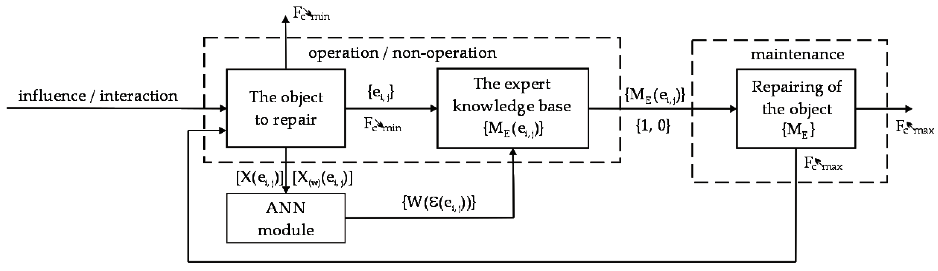
The current research work supporting the development of expert and advisory systems is focused on the issues related to the improvement of methods of acquiring specialist knowledge of a person, with the wide participation of modern solutions such as artificial intelligence and intelligent systems. This issue is presented in the works [16,17]. The issues of testing the reliability of wind farm equipment in its operation process are presented graphically in Figure 1.
Where the following stand for:
- -
- X(ei, j) is the diagnostic signal in the j-th element of the i-th set,
- -
- X(w)(ei, j) is a model signal for X(ei,j) signal,
- -
- FC is min. or max. value of the function of the use of the object,
- -
- W(ε(ei, j) = {3, 2, 1, 0}) is the diagnostic information-value of state assessment logics for element ”j” within ”i” module of the object.
Getting to know the current level of reliability of the devices used by the Wind Farm WF and other complex technical facilities is possible through their diagnosis. Diagnosis using inference (state recognition) in multi-valued logic is particularly useful [25]. At present, there is widespread progress in the development of specialized diagnostic devices. The issues are presented in the works [26,27]. It is particularly visible in the diagnostics of medical devices, energy technology, etc. However, these are diagnostic devices with an individual application for the selected device under test. There is no diagnostic device on the market with a wide (general) spectrum of practical diagnostic use. The works by Duer and others show that diagnostic devices represent a common and uniform technical solution. It is a modular solution with the following functional elements: measurement, diagnostic, and diagnostic knowledge base. For each diagnosed device or technical or technological process, only the measurement knowledge base and the measurement system, acquisition, etc., are relevant.
It is essential to comprehend the structure and principles of operation of technological devices and inaccurately diagnose them. Concerns relating to the operation of wind farm equipment are discussed in the following works [16].
In the work by Duer [45], he presented research on the reliability of Wind Farm equipment based on analytical models using reliability dependencies. However, the obtained results indicate that this approach is quite difficult to implement in simulation studies. The article presents the organization, implementation, and analysis of the simulations carried out for the evaluation of the quality of the maintenance system of wind farm equipment WF. The important aspect for the reader is to present models of wind farm equipment WF operation processes. The reader will find the issues of building and organizing the operation process of complex technical objects in [4]. Three models of wind farm equipment operation processes WF were used for the simulations. The model is Model A, an operation process of a wind power plant that uses an intelligent maintenance system with an artificial neural network. The second model is Model B, an operation process of the object which uses information in bivalent logic, a model with a maintenance system organized by planning its optimal prevention activities. The third is Model C, an operation process of a wind power plant with a maintenance system that is organized classically without any examination of the state in the assessment process: a strategy for object’s maintenance is based on manual planning of prevention activities and arbitrary operator’s selection of its scope.
The issues related to the description and testing of the individual elements that describe the operation process of technical facilities are well presented in publications. However, there are no studies that present the challenges of research into and organization of the operation process of complex technical facilities in a comprehensive manner. As a result, the article aims to model the reliability of WF Wind Farm equipment during its operation. This task will require solving the research problems presented below. The first issue is related to understanding and describing the problems of the diagnostics of WF devices. Another problem is understanding and describing the operation process (i.e., the use and maintenance) of Wind Farm devices. An important issue presented in the article is understanding and description of the organization of the technical maintenance system in the process of the operation of the facility tested.
The research on the reliability of wind farm technical devices with the use of intelligent systems was presented methodologically. For the WF operation process described in this way, its model was developed, and analytical relationships were determined on the basis of which the tested reliability values are determined in the form of the availability function (Kg(t)).
The article deals with the problem of testing the reliability of WF depending on the influence of one of the parameters on this value, i.e., the average time between successive failures. The application of this research parameter to the reliability of WF in such a way has not yet been undertaken in publications. The novelty of this article is also its use as a research tool in the form of the LabView computer program. The obtained results from the simulation tests are interesting and were not presented in the publications in the form presented in this article. The task of understanding the reliability of the Wind Farm equipment has become the main research goal presented in this article.
2. Methodology for Testing the Reliability of the Wind Farm Equipment in the Operation Process
Each study of any technical object, and even more so a simulation study, requires input data characterizing the actual operation process of the selected object class and its simulation models (Figure 2). The study of the actual operation of the facility is the basis for obtaining data for the simulation study of process models.
The required input data for the tests are the following quantities:
- -
- the time of use of the object T is the time the object is in a fit condition,
- -
- the time of removing the Ta object inoperability,
- -
- time of performing preventive repair of Tp,
- -
- period of projected (optimal) prevention θ*,
- -
- period of planned prophylaxis θ.
The source of the above data may be the observation of actual operation processes and a properly prepared and implemented simulation experiment. The results concerning the study of the actual operation process of various classes of technical objects are presented, among others, in the study. The simulation experiment consists of the following components (Figure 2):
- -
- Model of the tested facility operation process,
- -
- Test program,
- -
- Research tools—the use of a computer in research,
- -
- Analyze the obtained data.
- -
- The study of the models of the object operation processes was carried out using the same test criteria test conditions, such as:
- -
- Functions describing the object operation process and the inputs consumed,
- -
- Input data characterizing the operation process of complex objects.
To determine the appropriate measure characterizing the quality of the facility operation process, other quantities describing the efficiency of wind farm equipment used in the operation process should be analyzed.
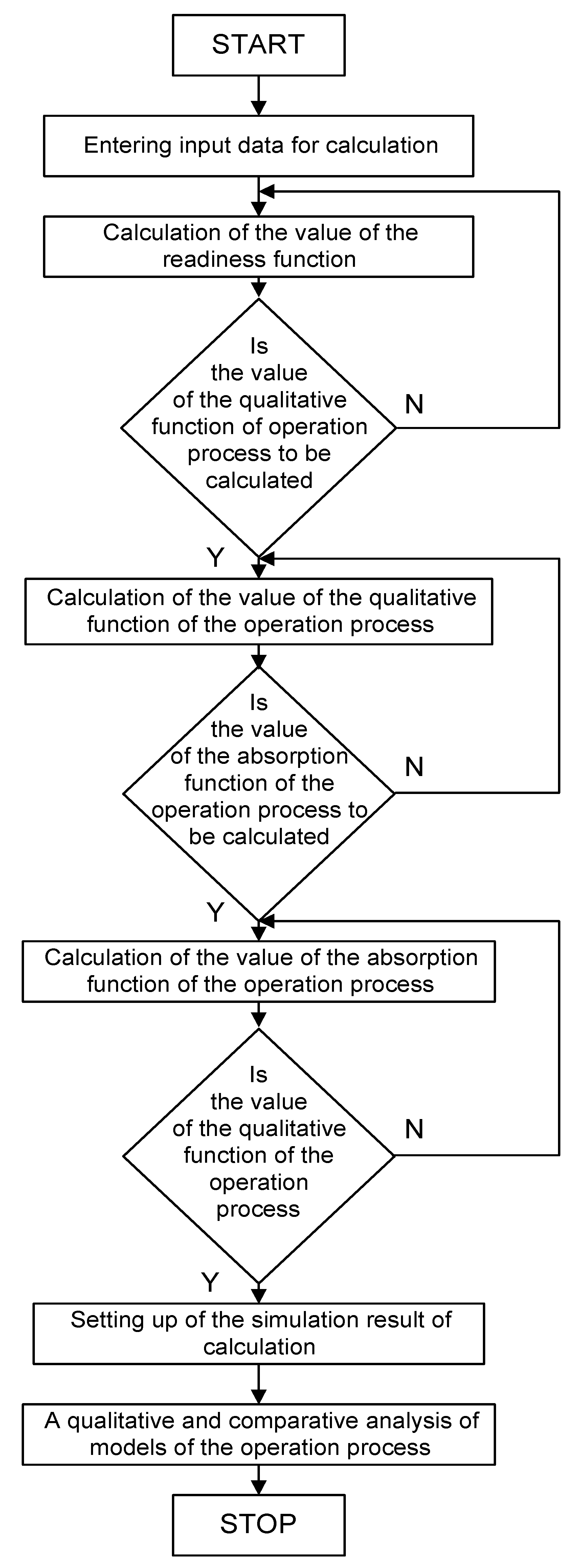
The methodology of testing the reliability of the wind farm equipment operation process is an activity of research, analysis, and evaluation in this area. In order to better understand the research activities in the field of reliability assessment of the wind farm equipment operation process, a graphical diagram of this operation was developed (Figure 2). The essential points in this algorithm are as follows:
- Understanding and describing the operation process (use and renovation) of wind farm equipment.
- Development of models of the operation process of wind farm equipment.
- Reliability simulation tests of the wind farm equipment operation process are carried out using the same computer program.
- The same input data is used in the reliability simulation tests of the wind farm equipment operation process.
- The results obtained from the simulation tests concerning the reliability of the operation process of wind farm equipment are presented graphically on common charts that present the quantities studied.
3. The Four-State Model of the Operation Process of Wind Farm Equipment
The analysis (Figure 1) shows that the wind farm equipment that is implemented (switched on) into operation is effectively used. When the wind farm devices are effectively used and the wind farm performs its functions as intended, then it is in the reliability state shown in Figure 2, which is called the effective SO usage state. With the time of use of a wind farm WF, its functional resource continues to decrease (reliability decreases). Measurement of the WF reliability level (value) is measured on an ongoing basis by diagnosing by the DIAG system. The DIAG system is an autonomous diagnostic device. The developed intelligent diagnostic system is a set of specialized technical devices along with a diagnostic card. The work of the DIAG program was verified on the basis of the diagnosis of functional devices of the Wind Farm. Problems of this type are quite modest in the literature [4].
Diagnostic information about the WF reliability level is assessed by the user on an ongoing basis. If the reliability of a wind farm drops below the acceptable level, the user (owner) of a wind farm decides on sending for renewal in an intelligent system. Therefore, such an event, when the WF cannot effectively carry out its tasks, is transferred to the reliability state in Figure 3, which is called the state of ineffective use–repair, restoration of utility properties S10. In Figure 1, the intelligent renewal (maintenance) system SERV is built by two subsystems: the subsystem of the expert maintenance knowledge base and the maintenance subsystem. The SERV system is an extensive expert system (computer program). The SERV system is responsible for determining the maintenance information on the basis of the diagnostic information obtained from the DIAG program. The developed SERV program is made on the basis of the presented stepwise algorithms for the process of renewing the functional properties of the wind farm. The developed solution of the SERV service system was subjected to practical action in the scope of determining the set of maintenance information for the renewal of the devices of the Wind Power Plant and other wind farms. Based on this information, the WF is renewed in the handling system. The renewed WF devices are returned to their use in the operation process (Figure 3).
During their operation, the WF devices require periodic and cyclical repair technical and technological works, such as inspections, and tests of wind power plant safety devices such as evacuation, crane, fire protection, and other devices. In a situation where the WF devices are subjected to repair and technological works, such a reliability state is called preventive shutdown (planned repair works) S1. During their effective use, WF devices are subject to constant supervision in the field of their safe use. One of the developed technical solutions that support the concept of a decision by the WF operator is the Wind Power Plant Expert system WPPEs expert program [4]. In situations threatening the safe operation of WF devices, the operator temporarily excludes WF from its use. Such a reliable state of WF presented in Figure 3 is called the state of ineffective use marked as S01.
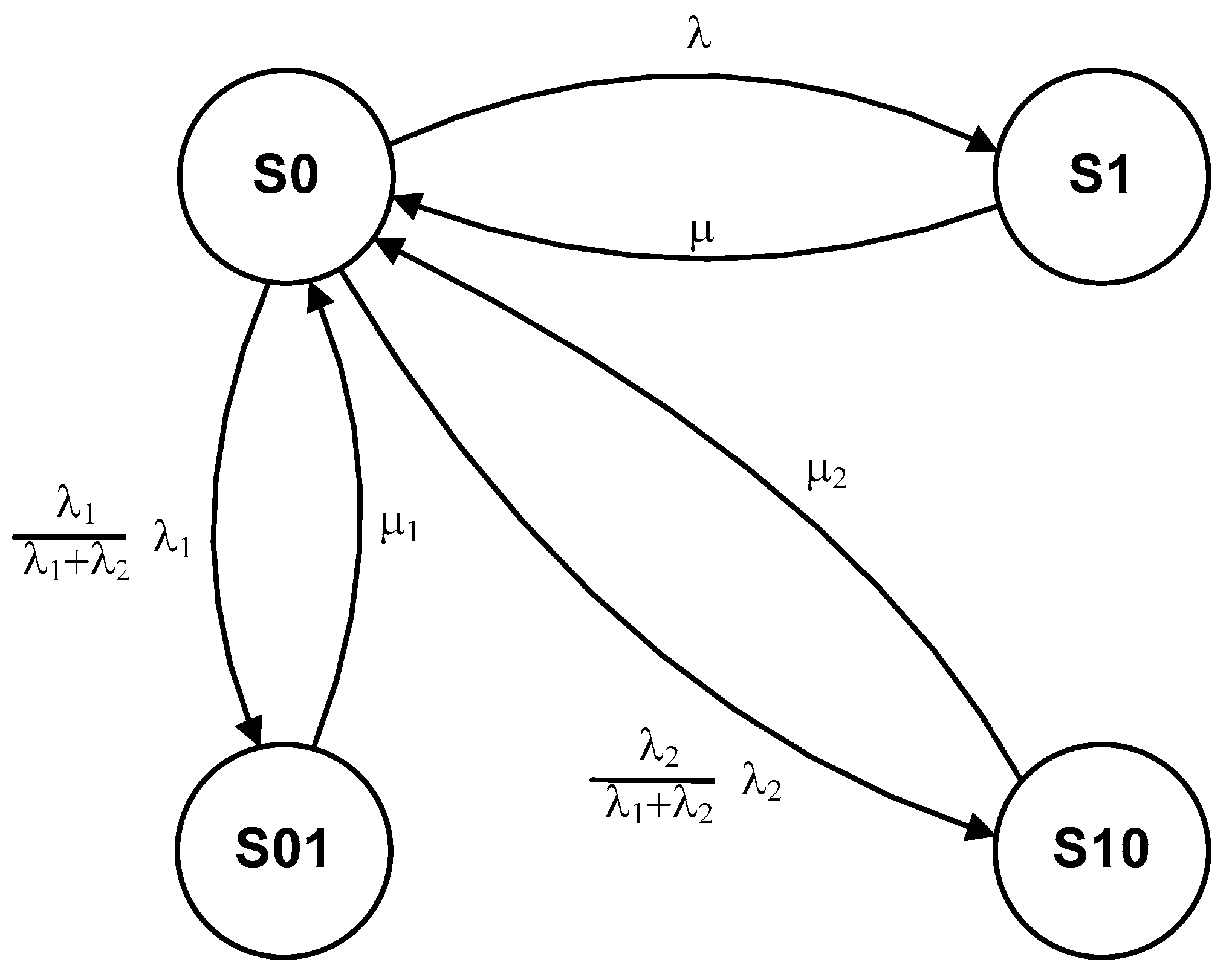
The problem related to the description of this type of exploitation process model was presented in the studies. The graphic form of this model is shown in Figure 3.
The analysis of the model of the operation process of the Wind Farm equipment presented in Figure 3 demonstrates that the facility may be in one of the following states:
- -
- S0—effective use of the facility,
- -
- S1—scheduled maintenance-preventive NP,
- -
- S01—unscheduled maintenance,
- -
- S10—ineffective use of the facility.
The transitions between the states in the model mean the following:
- -
- λ—has an interpretation of the intensity of the system’s transition from state S0 to state S1,
- -
- μ—has an interpretation of the system’s transition from state S1 to state S0,
- -
- —has an interpretation of the intensity of the transition of the system from the state S0 to state S01,
- -
- μ1—has an interpretation of the intensity of the transition of the system from the state S01 to state S0,
- -
- —has an interpretation of the intensity of the transition of the system from the state S0 to state S10,
- -
- μ2—has an interpretation of the intensity of the transition of the system from state S10 to state S0.
A technical facility used without the SERV expert system is damaged, and it modifies its place in the operating process. The object moves with intensity from state S0 to the state of ineffective use S10. The time of the technical object remaining in the state of ineffective use S10 is determined by the random variable τNA. The value of the useful life of an ineffective technical facility results from the wind farm operating conditions or from changes in weather conditions. The technical object, once the unfitness has been located and removed that determines the cause of its ineffective use, is again transferred to the S0 use state with an intensity of μ1. To identify the probability of the system remaining in the particular states, the network of crossings presented in Figure 4 shall be described with the following equations:
In the matrix notation, Relationship (2) can be presented as follows:
By transforming Equation (3), the following relationships were obtained:
Obviously enough, it is known that the relationship is correct:
Therefore:
Using Expression (8), it is possible to determine the values that are of interest and related to the probabilities of a wind farm system remaining in its various operating states. If the assumption is made that the modeling of the operation process consists in determining the probabilities of a wind farm system remaining in individual states {S0, S1, S01, S10}, then the following values need to be determined:
- -
- the likelihood function of the system being in a state S0,
- -
- the likelihood function of the system being in a state S1,
- -
- the likelihood function of the system being in a state S01,
- -
- the likelihood function of the system being in a state S10.
4. Results
4.1. Indices That Characterize the Process of Operating a Technical Facility
From the set illustrated in the literature [2,6,8,23,36] of these indicators characterizing the process of the operation of a technical object, the value best reflecting the operation process is the availability indicator Kg and the accessibility function Kg(t). The process for calculating the availability feature Kg(t) is generally simplified when calculated for a limit value at (t → ∞). The size is closely related to the stationary characteristics of the damage and maintenance process. Due to this, the availability rate of Kg is the most appropriate measure to set out the efficiency of the operation process, which links both the utility and economic characteristics of the facility. The accessibility factor Kg of the object is the likelihood of the event that the object is operational after a sufficiently long period of operation (t→ ∞). The accessibility factor Kg determines the average proportion of the technical object’s service life in the total service life, as represented by the following relationship:
where: Kg(t) is the medium value of the accessibility factor Kg.
4.2. Testing and Evaluation of the Reliability of Wind Farm Devices in the Operation Process Due to the Decrease in the Value of the Repair Time
The organization of the wind farm equipment operation process is subject to continuous improvement and improving it in terms of its technical implementation as well as the methods and forms of its organization. One of the important aspects in the modernization and modernization of the renewal process of wind farm equipment is the use of the intelligent SERV system in it. The SERV system is a large computer expert program that generates a set of maintenance instructions based on the input diagnostic information about the tested object and the existing expert knowledge base in the SERV system’s memory. The SERV system’s established service knowledge base serves as the foundation for the development and implementation of a smart system for the renewal and implementation of the process of restoring functional qualities. The functional qualities of wind farm devices decline with use as a result of the implementation of tasks envisaged for them. The current level of ownership of the functional characteristics of wind farm devices is examined and determined during the diagnosis process. Hence, the diagnostic information determined during the diagnosis is presented in the form of a “WF devices status table”. This information set, named the “Diagnostic Knowledge Base for WF Devices” DKB, is the input set for the SERV program. The SERV system develops a maintenance information set called the “Expert Knowledge Base for WF Equipment” EKB. The structure of EKB of WF devices is determined by the following sets of information:
- The service structure of the object is a set of information describing the internal structure of the object, which was determined on the basis of its functional model and the set of service information, adapted to the needs of the service. The service structure is determined by those basic elements of the facility that are in an incomplete or unfit condition and require renewal. The basic elements that require updating are called control elements. These elements are arranged in the facility’s maintenance structure, which is defined by the i-th service levels, and each of the i-th levels by the j-th service layers;
- Methods of classifying (grouping) elements in the object’s service structure, is a set of information describing the object’s service structure due to the nature and tasks of the element, which was determined based on its functional model and the set of service information and others. The specialist assigns one s-th class from the set of classes to each operating element, where: s = {I to VIII}. Assigning a specific class to an element in a service structure is assigning an element to a specific group of devices, eg a class: mechanical, electrical, etc. The object’s service structure adapted in this way is to adapt the nature of maintenance activities that are specific only to devices of a given group. This structure has a dimension like that of the operating structure, the elements describing this set of information are described through the i-th service levels, and each of the i-th levels is described by j-th service layers;
- Structures for renewing (servicing) maintenance elements is a set of maintenance information concerning the maintenance activities that must be performed in the process of renewing the maintenance elements of the facility. It is determined on the basis of assigning to each element of the maintenance structure a specific subset of maintenance activities, such as tuning, adjustment, maintenance, replacement, etc., selection of maintenance activities or their sets for individual operating elements are adapted to the current state, in which the structural elements of the facility are located; performing the required maintenance activities or their sets on individual maintenance elements will result in their transition to the state of suitability;
- Structure of service rules, this specialized set of object service information having the dimension of the internal structure of the object (levels × layers). This specialized maintenance knowledge base concerns the description of dependencies, rules, and relations in the scope of determining the information set of the object maintenance task, including structures: comparing the states of the object’s elements, object maintenance, object maintenance activities, classifying object elements. The handling rules provide the user of the object with answers, on how and how to effectively organize the process of handling the object. The set of facility maintenance rules is the basis, apart from the algorithm, for designing an appropriate computer program that supports the effective restoration of the facility’s operating features [4,45].
The renewal process of WF devices is organized on the basis of the set of maintenance information developed by the SERV system. The use of the SERV system in the process of refurbishing WF devices makes this type of refurbishment of this facility a modern solution, and at the same time innovative and effective. The issue of a refurbishment of wind farm devices is subject to continuous development to ensure that the restored usable resources of service elements have the character of a complete renovation, i.e., the same as the elements in the structure of a new facility (just implemented for use).
The problem of testing and assessing the reliability of wind farm devices in the operation process is a difficult task due to the decreasing value of the repair time. There is no description of this type of research in the literature. The article presents the thesis “Renewal of WF devices on the basis of information developed in the SERV system in a general manner and directly affects the reduction of the time of restoring the resource of functional properties (the object’s presence in the maintenance system), and thus reducing the repair time” (Figure 1). The whole average duration of the renewal procedure (the object’s stay in the handling system) is referred to as the average repair time. The article’s research premise concerning the prospect of reducing the time it takes to repair wind farm devices stems from the essence of the facility renovation system, which is made possible by the usage of an intelligent SERV system. The intelligent SERV system used in the process of refurbishment of WF devices develops an effective “Knowledge base for servicing WF devices”. In this set of maintenance information, the SERV system optimizes the service structure of WF equipment. The SERV system defines a set of operating elements of WF devices that have {3} states—the states of availability and do not require the need to restore the resource of operational properties. The size of the average repair time of WF devices is also influenced by the organization of the renewal process based on information from the SERV system.
On the basis of information from the SERV system, the service elements are renewed for the appropriate level based on their current state from the {3, 2, 1, 0} set. Then, the implementation of the renewal process (implementation of technical and technological activities) is also optimal. Only those technological activities (renewing service elements) are performed that are required (developed by the SERV system) to fully renew the elements of the WF devices. Therefore, the presented problems of organization and implementation of the wind farm equipment renewal process will result in reducing the repair time. The results obtained from the testing and evaluation of the reliability of wind farm devices in the operation process due to the decrease in the value of the repair time are presented in Table 1 and Figure 4, Figure 5, Figure 6 and Figure 7.
The analysis of the test results presented in Table 1 and in Figure 4, Figure 5, Figure 6 and Figure 7 shows that for the value of the mean repair time equal to (0.3), the reliability value determined in the study in the form of the readiness factor Kg (1) is 0.999793711044.
The assumed value of the average repair time of (0.3) means that in the maintenance system based on information from the SERV system, the renewal time of WF devices was reduced to 70% concerning the average value of the renewal time of wind farm devices implemented in the maintenance system organized traditionally (classic) [40,41]. The research verified (tested) the impact of the average repair time equal to the test value (1.0) appropriate for the renewal of wind farm devices in the maintenance system organized classically (without support from the use of intelligent systems). For the mean repair time value equal to (1.0), the determined reliability of wind farm devices renewed in the maintenance process in the form of the availability factor Kg (2) is 0.99943517 (Figure 8).
The analysis of the Kg (1) and Kg (2) readiness factor values allows for determining the possible increase in the value in the form of the readiness factor ΔKg on the basis of the relationship: ΔKg = Kg (1)−Kg (2), hence the value ΔKg = 0.000358. The analysis of the research results presented in (Figure 1) allows for the formulation of the following conclusions.
- Renewal of wind farm devices in the maintenance system organized on the basis of information developed in intelligent systems, including: diagnostic (DIAG) and maintenance (SERV) significantly increases the reliability of the renovated facility.
- The use of innovative intelligent systems in the renewal process of wind farm devices brings an increase in the reliability of the renewable wind farm devices in the form of the readiness factor value is ΔKg = 0.000358.
- The intelligent SERV system is a good computer tool that effectively supports the construction and organization of maintenance systems renewing the wind farm equipment.
4.3. Testing and Evaluation of the Reliability of Wind Farm Devices in the Operation Process Due to Changes in the Value of Time between Successive Failures of Wind Farm Devices
It is important to test and evaluate the reliability of wind farm devices in the operation process due to changes in the value of time between successive failures of wind farm devices and a research aspect that is difficult to implement. The average value of the time between successive failures of wind farm devices in the operation process is one of the basic indicators in assessing its reliability in (Table 2) and (Figure 9, Figure 10, Figure 11, Figure 12 and Figure 13). The average value of the time between successive failures of WF devices is directly related to the quality and accuracy of the device renewal, the method and strategy used in the renovation process, the full use of service information about the device, and other factors, and can be used to assess the reliability of WF devices refurbished in an intelligent maintenance system. As a result, the influence of the average value of time between successive failures on the reliability quality of wind farm equipment was evaluated in the next simulation study.
The study assumed the range of changes in the mean value of the time between successive lesions in the range of {1000 ÷ 3000} [h]. The results obtained from testing the average value of the time between successive failures of wind farm devices for the reliability of wind farm devices in the operation process are presented in Table 2 and Figure 9, Figure 10, Figure 11 and Figure 12.
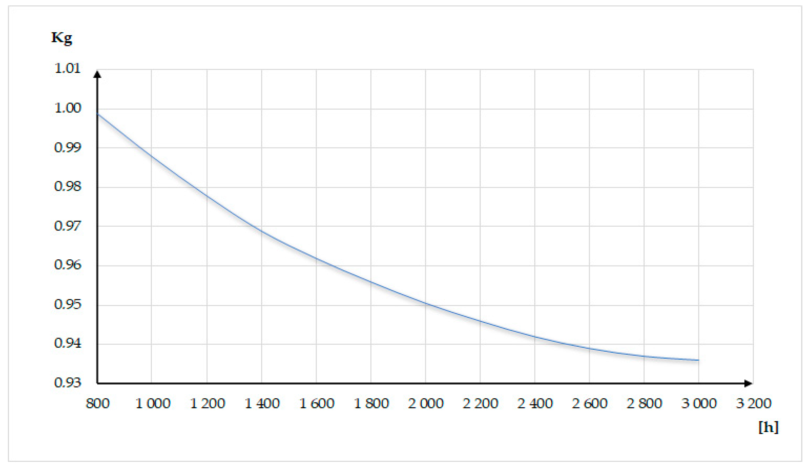
The analysis of the test results presented in Table 2 and Figure 9, Figure 10, Figure 11, Figure 12 and Figure 13 shows that for the value of the mean time between successive failures amounting to 1000 [h], the reliability value determined in the test in the form of the readiness factor Kg (1) is 0.999815173. The adopted value of the average time between successive failures amounting to 3000 [h] means that the WF devices are fully refurbished and have the property of use at the level of a new facility.
The impact of the average time between successive failures on the quality of the service process, as well as the impact on the level of reliability of WF devices, was examined for this value in the interval {1000 ÷ 3000 [h]} (Figure 13).
The study assumes that the value of the average time between successive failures amounting to 1000 [h] is appropriate for the reliability level of wind farm equipment obtained as a result of the renewal carried out in the maintenance system organized in a traditional (classic) manner [40,41].
The research verified (tested) the flow of the average time between successive failures, amounting to (1000 [h]), appropriate for the renewal of wind farm devices in the maintenance system organized classically (without support from the use of intelligent systems). In the meantime between successive failures of (3000 [h]), the reliability determined in the simulation test in the form of the readiness factor Kg (2) of wind farm devices renewed in the service process is 0.99942755.
The analysis of the Kg (1) and Kg (2) readiness factor values allows for determining the possible increase in the value in the form of the readiness factor ΔKg based on the relationship: ΔKg = Kg (1)−Kg (2), hence the value ΔKg = 0.0003876. The analysis of the research results presented in (Figure 1) allows for the formulation of the following conclusions.
- Research on the reliability of wind farm devices for the meantime between successive failures confirms that the renewal of wind farm devices in a maintenance system organized on the basis of information developed in intelligent systems, including diagnostic DIAG and maintenance SERV significantly increases the reliability of the renovated facility.
- The use of efficient and modern intelligent systems for renewing wind farm devices brings a significant increase in the reliability of the renewable wind farm devices in the form of the readiness factor value is ΔKg = 0.0003876.
- The developed intelligent SERV system is a good computer tool that effectively supports the design and organization of systems for renewing wind farm devices.
5. Discussion
The problems presented in this paper in reliability studies of the exploitation process of the WF wind farm equipment are particularly well presented in the publication [4]. This paper presents a study of wind farm equipment in the aspect of reliability testing in the aspect of the application of an intelligent expert system to support decision-making by the system operator in the safe supervision of its use. In this work, the following three models of the operation process were developed:
- -
- Model A, reporting the operation process of wind power installations equipped with intelligent systems supporting decision-making regarding the safety in use,
- -
- Model B, describing the process of operating wind farm equipment not equipped with any smart support schemes and without the WPPES system,
- -
- Model C, reporting a simple (conceptual) process of operating wind farm facilities.
For the analytical description of the developed models of the WF equipment operation process, the Kolmogorov–Chapman equations were adopted, which are widely presented in the literature [24]—Nakagawa, T. Maintenance Theory of Reliability; Springer: London, UK, 2005. In the simulation analysis of the reliability of the Wind Farm equipment, the basic reliability quantity of the WF understudy will be determined in the form of the readiness factor Kg(t).
The novelty of this paper about other publications on the reliability of technical devices is the subject of research.
Only in this work, among other publications, was the study of the reliability of wind farm equipment undertaken in the aspect:
- Testing and evaluation of the reliability of wind farm devices in the operation process due to the decrease in the value of the repair time.
- Testing and evaluation of the reliability of wind farm devices in the operation process due to changes in the value of time between successive failures of wind farm devices.
The subject matter in the first point of the research is extremely important and of great practical significance. Such research problems as those presented in points 1 and 2 were not presented in publications. The research topic undertaken in pt. 1. concerns modernization of the process of renewing wind farm equipment used in the process of its exploitation. The paper presents that the modernization of the renewal process of the WF is performed by using an intelligent SERV renewal system. Based on information from the SERV system, the service elements are renewed for the appropriate level based on their current state from the {3, 2, 1, 0} set. Then, the implementation of the renewal process (implementation of technical and technological activities) is also optimal. Only those technological activities (renewing service elements) are performed that are required (developed by the SERV system) to fully renew the elements of the WF devices. Therefore, the presented problems of organization and implementation of the wind farm equipment renewal process will result in reducing the repair time.
Having applied the SERV system in the operation process of WF equipment, the task of a simulation study of its effectiveness was undertaken. For the simulation study, it was assumed that decreasing the duration of the process of renewal Todn of WF devices will be studied for the interval {0.2 to 1.00} hour. For such an interval of possible changes in the duration of the process of renewal Todn of WF devices, an increase in the tested value of the readiness factor ΔKg = 0.045 was obtained. On this basis, it can be concluded that the improvement (modernization) of the process of renewal Todn of WF devices is an important task and affects the increase in the reliability of WF devices.
Another research problem presented in the second point of the research concerned the influence of the value of time between Tmu in the operation process of PE equipment on its reliability. It is research that is new in publications on PE topics. In many publications [7,16,27,28,29,30,31,32,33,34,35,36,37,38,39] the time between failures Tmu in the process of technical equipment operation is identified with the reliability index of these devices. On this basis, it can be said that the greater the value of the time between failures Tmu in the process of technical equipment operation, this equipment has higher reliability. In this paper, the task was undertaken to check in practice in research how the value of time between failures Tmu in the process of WF equipment operation affects the increase of its reliability. In the conducted research it was assumed that the value of time between failures Tmu in the process of operation of WF equipment will vary in the range {from 1000 to 3000} hours. The results obtained from the tests show that the possible growth of the studied magnitude of the readiness factor ΔKg = 0.07. The value of this reliability measure in the form of a readiness factor Kg is significant. Therefore, it can be concluded that the pursuit, in the process of WF equipment operation, to increase the value of time between failures Tmu in the operation process of PE equipment is an important direction for increasing reliability.
6. Conclusions
The problem of testing the reliability properties of wind farm equipment during its operation, as presented in the article, is a difficult organizational and technical task. The difficulty of this result is also due to the acquisition of input data for the research. Numerical data describing the operation process of the Wind Farm equipment was obtained through research carried out over a long period of time. It was assumed that the observation time (measurement of downtime and useful life, etc.) would be sufficient for one year. On the other hand, the reliability tests of the Wind Farm devices will be carried out as a simulation test. This type of research requires the knowledge and description of the actual operation process of the Wind Farm equipment and the determination of reliable input data for the research. At the core of each research is a good research plan (how and how to test) for the wind farm equipment. The basis for the simulation study of the operation process of the Wind Farm equipment is the developed model of the organization of the operation process. Hence, a model of the wind farm equipment operation process was developed, which in the literature is called the four-stage model. The following reliability values were investigated in the simulation tests to determine the reliability of the Wind Farm device in the process of operation with changes:
- -
- the value of the average repair time equal to (0.3) [h], the reliability value in the form of the Kg (1) readiness coefficient determined in the test is the highest and amounts to 0.99979371,
- -
- the value of the mean time between successive failures (3000 [h]), the reliability determined in the simulation test in the form of the readiness factor Kg (2) of wind farm devices renewed in the service process is the highest and amounts to 0.99942755.
Author Contributions
Conceptualization, resources, methodology, software, validation, A.O.; formal analysis, investigation, data curation, A.H. and M.W.; writing—original draft preparation, writing—review and editing, visualization, S.D. and R.D.; supervision, project administration, funding acquisition, J.P. All authors have read and agreed to the published version of the manuscript.
Funding
This research was funded by the Faculty of Electronics and Informatics, Technical University of Koszalin, 2. Sniadeckich St., 75-620 Koszalin, Poland.
Data Availability Statement
The data presented in this article are available at the request of the corresponding author.
Conflicts of Interest
The authors declare no conflict of interest.
Abbreviation
| Symbols | |
| X(ei,j) | diagnostic signal in jth element of ith set |
| X(w)(ei,j) | model signal for X(ei,j) signal |
| FC max | max. value of the function of the use of the object |
| W(ε(ei,j)) = {2, 1, 0}) | valued of state assessment logics for jth element within ith module (from the set of the accepted three-value logic of states’ assessment) |
| Kg(t) or Kg | the average value of availability function or factor Kg |
| Fc | the quality function of the object’s operation process |
| Fch | function of the object exploitation process |
| λ | damage intensity |
| To | simulation test time of the object |
| μ | repair intensity |
| λ1 | intensity of type I inspections |
| μ1 | type I operational maintenance intensity |
| λ2 | intensity of type II inspections |
| μ2 | type II operational maintenance intensity |
| P0 | probability of the system being in state S0 |
| P1 | probability of the system being in state S1 |
| P01 | probability of the system being in state S01 |
| P10 | probability of the system being in state S10 |
| S0 | effective use of the object |
| S1 | scheduled maintenance–preventive NP |
| S01 | unscheduled maintenance |
| S10 | repair, restoration of utility properties ineffective use of the object |
| Acronyms | |
| WPPES | Wind Power Plant Expert System |
| SERV | intelligent operating system |
| DIAG | intelligent diagnostic system |
References
- Abo-Khalil, A.G.; Alghamdi, A.I.; Tlili, A.; Eltamaly, A.M. Current Controller Design for DFIG-based 426 Wind Turbines Using State Feedback Control. IET Renew. Power Gener. 2019, 13, 1938–1949. [Google Scholar] [CrossRef]
- Eltamaly, A.M. Modeling of wind turbine driving permanent magnet generator with maximum power 383point tracking system. J. King Saud Univ.-Eng. Sci. 2007, 19, 223–236. [Google Scholar]
- Andalib, C.; Liang, X.; Zhang, H. Fuzzy-Secondary-Controller-Based Virtual Synchronous Generator 386 Control Scheme for Interfacing Inverters of Renewable Distributed Generation in Microgrids. IEEE Trans. Ind. Appl. 2018, 54, 1047–1061. [Google Scholar] [CrossRef]
- Duer, S. Assessment of the Operation Process of Wind Power Plant’s Equipment with the Use of an Artificial Neural Network. Energies 2020, 13, 2437. [Google Scholar] [CrossRef]
- Badrzadeh, B.; Gupta, M.; Singh, N.; Petersson, A.; Max, L.; Høgdahl, M. Power system harmonic analysis in wind power plants-Part I: Study methodology and techniques. In Proceedings of the IEEE Industry Applications Society Annual Meeting, Las Vegas, NV, USA, 7–11 October 2012; pp. 1–11. [Google Scholar]
- Kunjumuhammed, L.P.; Pal, B.C.; Oates, C.; Dyke, K.L. Electrical oscillations in wind farm systems: Analysis and insight based on detailed modeling. IEEE Trans. Sustain. Energy 2016, 7, 51–62. [Google Scholar] [CrossRef] [Green Version]
- Pogaku, N.; Prodanovic, M.; Green, T.C. Modeling, analysis and testing of autonomous operation of an inverter-based microgrid. IEEE Trans. Power Electron. 2007, 22, 613–625. [Google Scholar] [CrossRef] [Green Version]
- Shahanaghi, K.; Babaei, H.; Bakhsha, A. A Chance Constrained Model for a Two Units Series Critical System Suffering from Continuous Deterioration. Int. J. Ind. Eng. Prod. Res. 2009, 20, 69–75. [Google Scholar]
- Sun, J. Impedance-based stability criterion for grid-connected inverters. IEEE Trans. Power Electron. 2011, 26, 3075–3078. [Google Scholar] [CrossRef]
- Hojjat, A.; Shih, L.H. Machine Learning, Neural Networks, Genetic Algorithms and Fuzzy Systems; John Wiley & Sons, Inc.: Hoboken, NJ, USA, 1995; p. 398. [Google Scholar]
- Buchannan, B.; Shortliffe, E. Rule—Based Expert Systems; Addison—Wesley Publishing Company: London, UK; Amsterdam, The Netherlands; Don Mills, ON, Canada; Sydney, Australia, 1985; p. 387. [Google Scholar]
- Hayer-Roth, F.; Waterman, D.; Lenat, D. Building Expert Systems; Addison—Wesley Publishing Company: Boston, MA, USA, 1983; p. 321. [Google Scholar]
- Waterman, D. A Guide to Export Systems; Addison—Wesley Publishing Company: Boston, MA, USA, 1986. [Google Scholar]
- Wiliams, J.M.; Zipser, D. A learning Algorithm for Continually Running Fully Recurrent Neural Networks. Neural Comput. 1989, 1, 270–280. [Google Scholar] [CrossRef]
- Linz, P. An Introduction to Formal Languages and Automata; University of California: Davis, CA, USA, 2002. [Google Scholar]
- Bernatowicz, D.; Duer, S.; Wrzesień, P. Expert system supporting the diagnosis of the wind farm equipments. In Communications in Computer and Information Science; Springer: Poznan, Poland, 2018; Volume 928, pp. 432–441. [Google Scholar]
- Gupta, M.M.; Jin, L.; Homma, N. Static and Dynamic Neural Networks, From Fundamentals to Advanced Theory; John Wiley and Sons, Inc.: Hoboken, NJ, USA, 2003; p. 718. [Google Scholar]
- Tang, L.; Liu, J.; Rong, A.; Yang, Z. Modeling and genetic algorithm solution for the slab stack shuffling problem when implementing steel rolling schedules. Int. J. Prod. Res. 2002, 40, 272–276. [Google Scholar] [CrossRef]
- Mathirajan, M.; Chandru, V.; Sivakumar, A.I. Heuristic algorithms for scheduling heat-treatment furnaces of steel casting industries. Sadahana 2007, 32, 111–119. [Google Scholar] [CrossRef] [Green Version]
- Kacalak, W.; Majewski, M. New Intelligent Interactive Automated Systems for Design of Machine Elements and Assemblies. In Lecture Notes in Computer Science; Springer: Berlin, Germany, 2012; pp. 115–122. [Google Scholar]
- Lipinski, D.; Majewski, M. System for monitoring and optimization of micro- and nano-machining processes using intelligent voice and visual communication. In Lecture Notes in Computer Science; Springer: Berlin, Germany, 2013; Volume 8206, pp. 16–23. [Google Scholar]
- Majewski, M.; Kacalak, W. Smart control of lifting devices using patterns and antipatterns. In Artificial Intelligence Trends in Intelligent Systems; Advances in intelligent systems and computing; Springer: Cham, Switzerland, 2017; Volume 573, pp. 486–493. [Google Scholar] [CrossRef]
- Majewski, M.; Kacalak, W. Innovative intelligent interaction systems of loader cranes and their human operators. In Artificial Intelligence Trends in Intelligent Systems; Advances in intelligent systems and computing; Springer: Cham, Switzerland, 2017; Volume 573, pp. 474–485. [Google Scholar] [CrossRef]
- Duer, S.; Bernatowicz, D.; Wrzesień, P.; Duer, R. The diagnostic system with an artificial neural network for identifying states in multi-valued logic of a device wind power. In Communications in Computer and Information Science; Springer: Poznan, Poland, 2018; Volume 928, pp. 442–454. [Google Scholar]
- Zurada, I.M. Introduction to Artificial Neural Systems; West Publishing Company: St. Paul, MN, USA, 1992; p. 324. [Google Scholar]
- Bedkowski, L.; Dabrowski, T. Basic of the Maintenance Theory; Publishing House of WAT: Warsaw, Poland, 2006; p. 187. [Google Scholar]
- Dyduch, J.; Paś, J.; Rosiński, A. The Basic of the Exploitation of Transport Electronic Systems; Publishing House of Radom University of Technology: Radom, Poland, 2011. [Google Scholar]
- Epstein, B.; Weissman, I. Mathematical Models for Systems Reliability; CRC Press/Taylor & Francis Group: Boca Raton, FL, USA, 2008. [Google Scholar]
- Klimczak, T.; Paś, J. Selected Issues of the Reliability and Operational Assessment of a Fire Alarm System; Maintenance and Reliability: Warsaw, Poland, 2019; Volume 21, pp. 553–561. [Google Scholar]
- Siergiejczyk, M.; Paś, J.; Rosiński, A. Issue of reliability–exploitation evaluation of electronic transport systems used in the railway environment with consideration of electromagnetic interference. IET Intell. Transp. Syst. 2016, 10, 587–593. [Google Scholar] [CrossRef]
- Siergiejczyk, M.; Rosiński, A. Analysis of power supply maintenance in transport telematics system. Solid State Phenom. 2014, 210, 14–19. [Google Scholar] [CrossRef]
- Dhillon, B.S. Applied Reliability and Quality, Fundamentals, Methods and Procedures; Springer: London, UK, 2006; p. 186. [Google Scholar]
- Rychlicki, M.; Kasprzyk, Z.; Rosiński, A. Analysis of Accuracy and Reliability of Different Types of GPS Receivers. Sensors 2020, 20, 6498. [Google Scholar] [CrossRef] [PubMed]
- Stawowy, M.; Olchowik, W.; Rosiński, A.; Dąbrowski, T. The Analysis and Modelling of the Quality of Information Acquired from Weather Station Sensors. Remote Sens. 2021, 13, 693. [Google Scholar] [CrossRef]
- Paś, J.; Rosiński, A.; Chrzan, M.; Białek, K. Reliability-Operational Analysis of the LED Lighting Module Including Electromagnetic Interference. IEEE Trans. Electromagn. Compat. 2020, 62, 2747–2758. [Google Scholar] [CrossRef]
- Nakagawa, T. Maintenance Theory of Reliability; Springer: London, UK, 2005. [Google Scholar]
- Nakagawa, T.; Ito, K. Optimal inspection policies for a storage system with degradation at periodic tests. Math. Comput. Model. 2000, 31, 191–195. [Google Scholar]
- Pokoradi, L. Logical Tree of Mathematical Modeling. Theory Appl. Math. Comput. Sci. 2015, 5, 20–28. [Google Scholar]
- Dempster, A.P. Upper and lower probabilities inducted by a multi-valued mapping. Ann. Math. Stat. 1967, 38, 325–339. [Google Scholar] [CrossRef]
- Smyczek, J.; Zajkowski, K. Simulation of overvoltages for switching off lagging load from mains. In Proceedings of the 2nd International Industrial Simulation Conference, Malaga, Spain, 7–9 June 2004; pp. 278–281. [Google Scholar]
- Zajkowski, K. Settlement of reactive power compensation in the light of white certificates. In E3S Web of Conferences 19, UNSP 01037; EDP Sciences: Les Ulis, France, 2017. [Google Scholar] [CrossRef] [Green Version]
- Zajkowski, K. The method of solution of equations with coefficients that contain measurement errors, using artificial neural network. Neural Comput. Appl. 2012, 24, 431–439. [Google Scholar] [CrossRef] [Green Version]
- Zajkowski, K. An innovative hybrid insulation switch to enable/disable electrical loads without over voltages. In E3S Web of Conferences 19, UNSP 01033; EDP Sciences: Les Ulis, France, 2017. [Google Scholar] [CrossRef]
- Zajkowski, K. Two-stage reactive compensation in a three-phase four-wire systems at no sinusoidal periodic waveforms. Electr. Power Syst. Res. 2020, 184, 106296. [Google Scholar] [CrossRef]
- Duer, S.; Zajkowski, K.; Harničárová, M.; Charun, H.; Bernatowicz, D. Examination of Multivalent Diagnoses Developed by a Diagnostic Program with an Artificial Neural Network for Devices in the Electric Hybrid Power Supply System “House on Water”. Energies 2021, 14, 2153. [Google Scholar] [CrossRef]
Figure 1.
Diagram of operation process for technical object utilizing the artificial neural network.
Figure 1.
Diagram of operation process for technical object utilizing the artificial neural network.

Figure 2.
Algorithm of simulation investigations concerning the quality of the assessment of the operation process of the technical object.
Figure 2.
Algorithm of simulation investigations concerning the quality of the assessment of the operation process of the technical object.

Figure 3.
Diagram of the operation process of a Wind Equipment Farm not equipped with any intelligent expert systems SERV.
Figure 3.
Diagram of the operation process of a Wind Equipment Farm not equipped with any intelligent expert systems SERV.

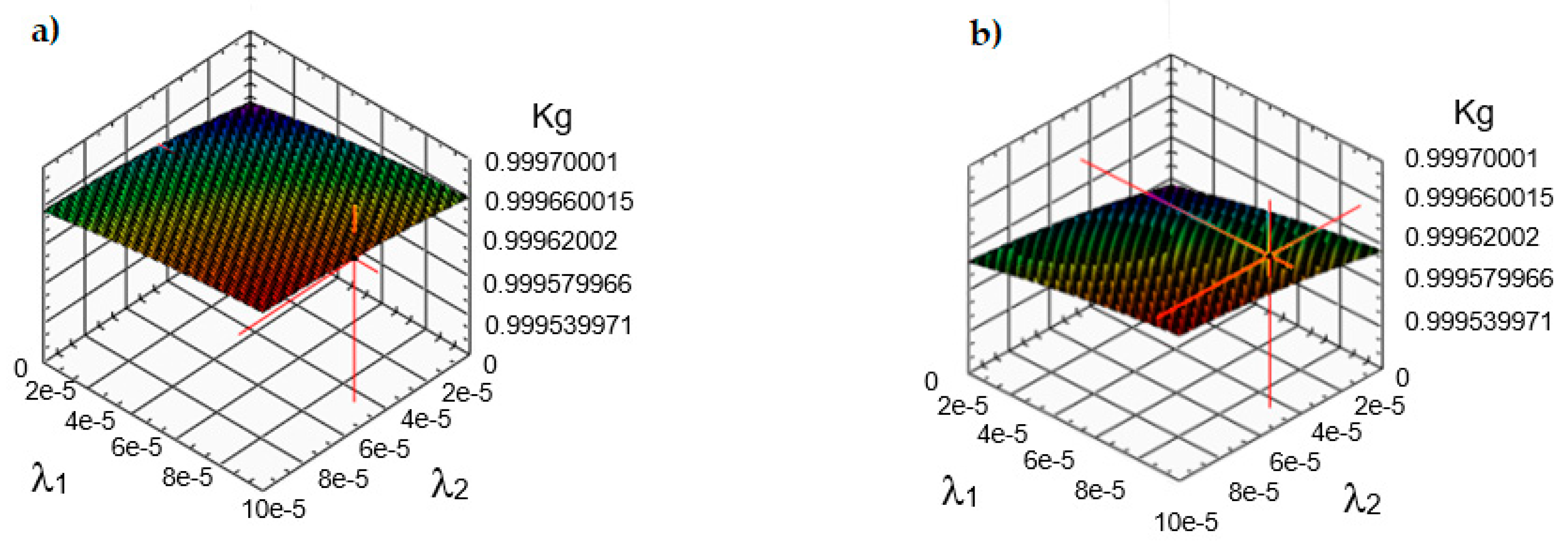
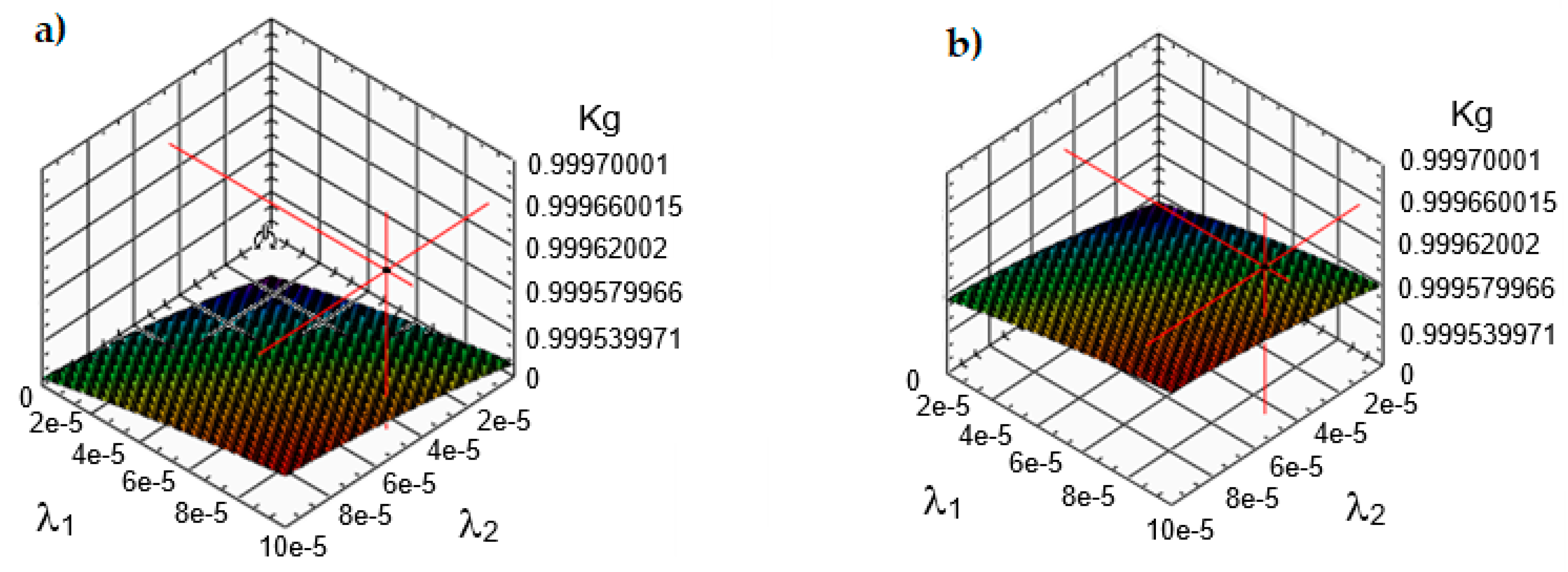
Figure 4.
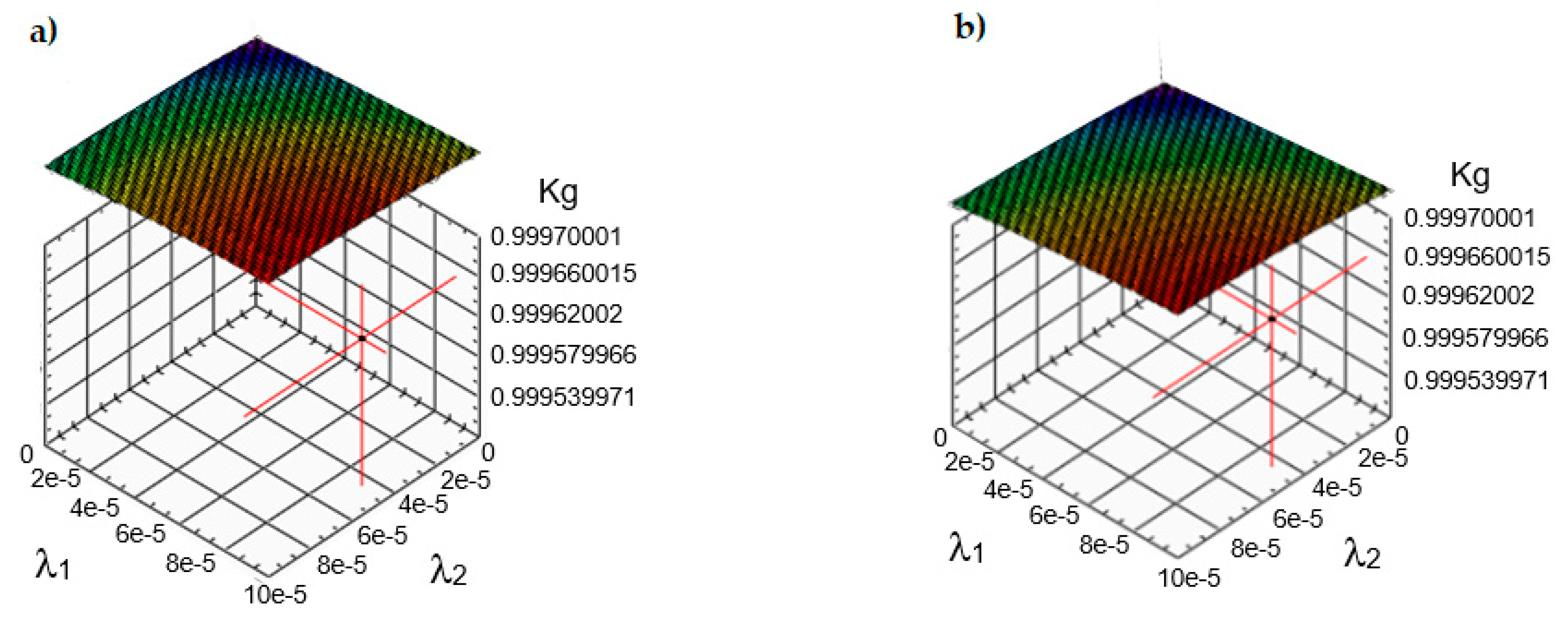
Graphs of the Kg availability coefficient in the process of testing the reliability of wind farm devices by changing the value of the average repair time for constant parameters, including: type I mean service time = 0.8 [h]; type II mean operating time = 1.3 [h]; mean time between successive failures = 1200 [h], where: (a) mean repair time 0.3 [h]; (b) average repair time 0.4 [h].
Figure 4.
Graphs of the Kg availability coefficient in the process of testing the reliability of wind farm devices by changing the value of the average repair time for constant parameters, including: type I mean service time = 0.8 [h]; type II mean operating time = 1.3 [h]; mean time between successive failures = 1200 [h], where: (a) mean repair time 0.3 [h]; (b) average repair time 0.4 [h].

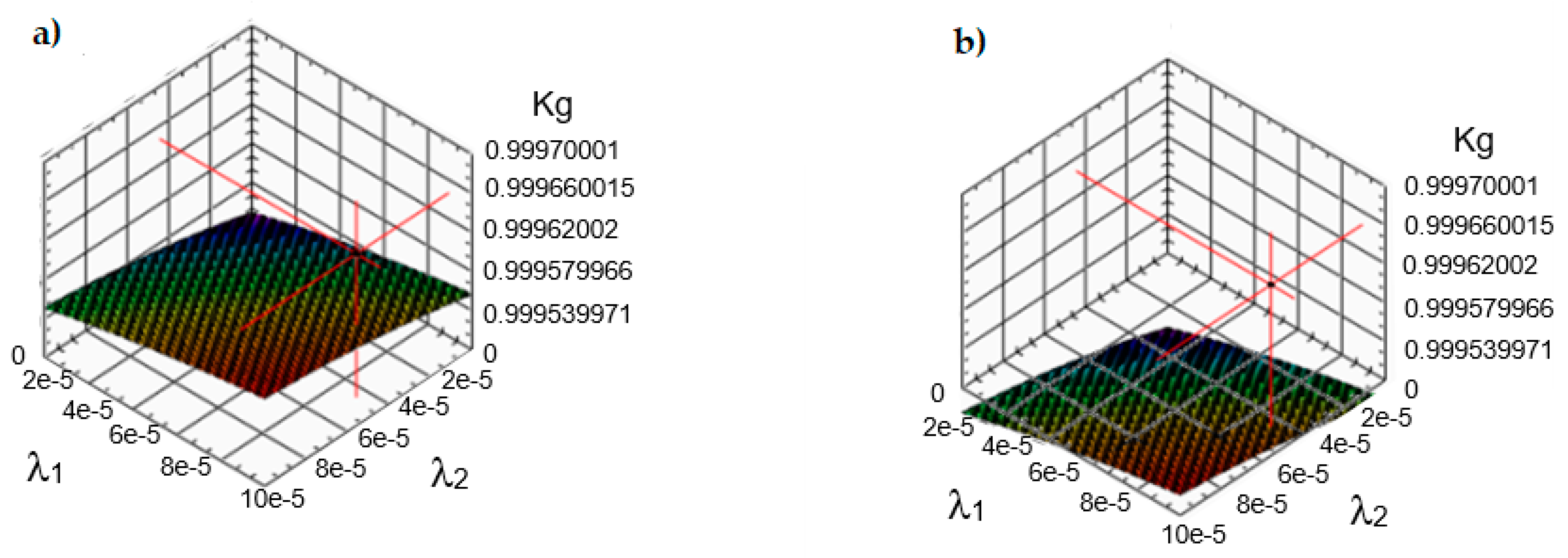
Figure 5.
Graphs of the Kg availability coefficient in the process of testing the reliability of wind farm devices by changing the value of the average repair time for constant parameters, including: type I mean service time = 0.8 [h]; type II mean operating time = 1.3 [h]; mean time between successive failures = 1200 [h]. where: (a) average repair time 0.5 [h]; (b) average repair time 0.6 [h].

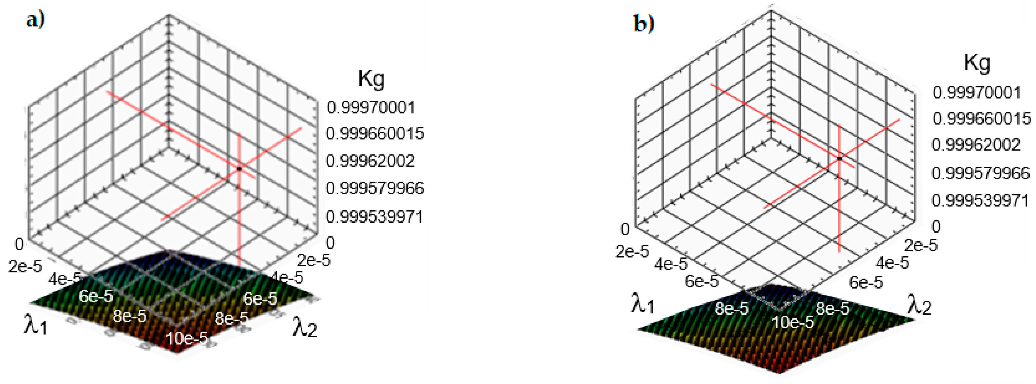
Figure 6.
Graphs of the Kg availability coefficient in the process of testing the reliability of wind farm devices by changing the value of the average repair time for constant parameters, including: type I mean service time = 0.8 [h]; type II mean operating time = 1.3 [h]; mean time between successive failures = 1200 [h], where: (a) mean repair time 0.7 [h]; (b) average repair time 0.8 [h].

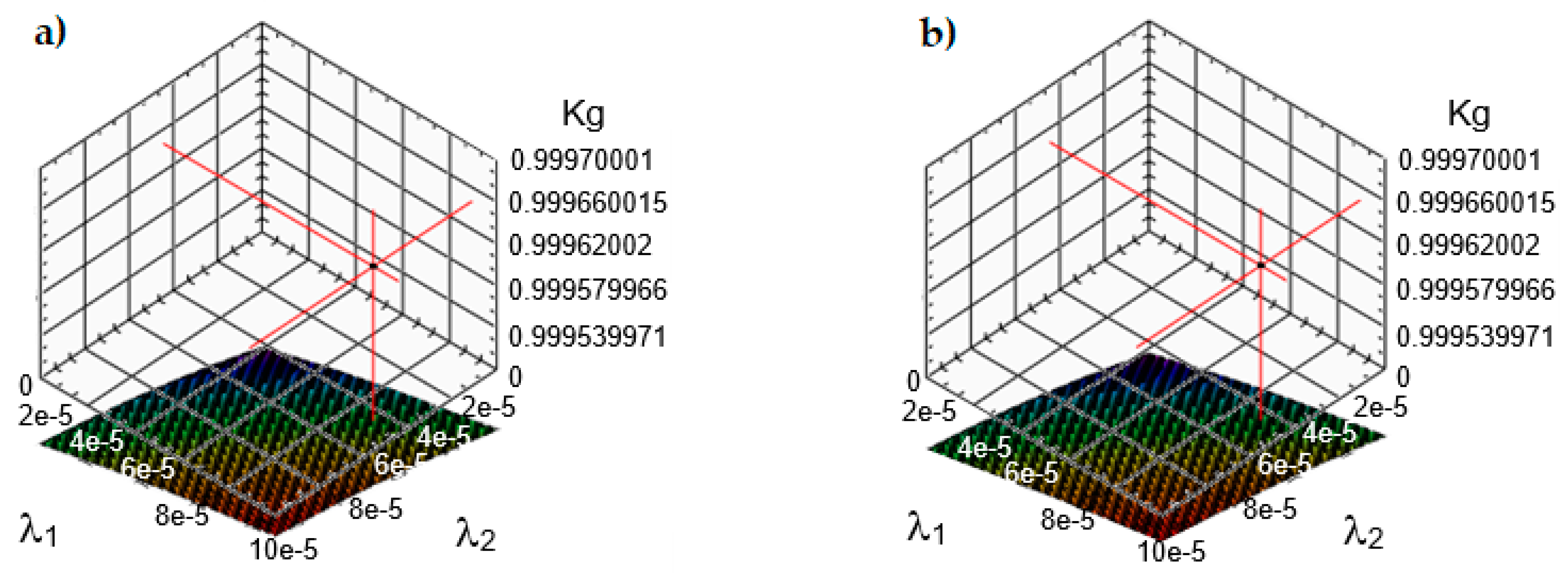
Figure 7.
Graphs of the Kg availability coefficient in the process of testing the reliability of wind farm devices by changing the value of the average repair time for constant parameters, including: type I mean service time = 0.8 [h]; type II mean operating time = 1.3 [h]; mean time between successive failures = 1200 [h], where: (a) mean repair time 0.9 [h]; (b) average repair time 1.0 [h].

Figure 8.
Graph of the reliability of wind farm devices in the operation process as a function of repair time.
Figure 8.
Graph of the reliability of wind farm devices in the operation process as a function of repair time.

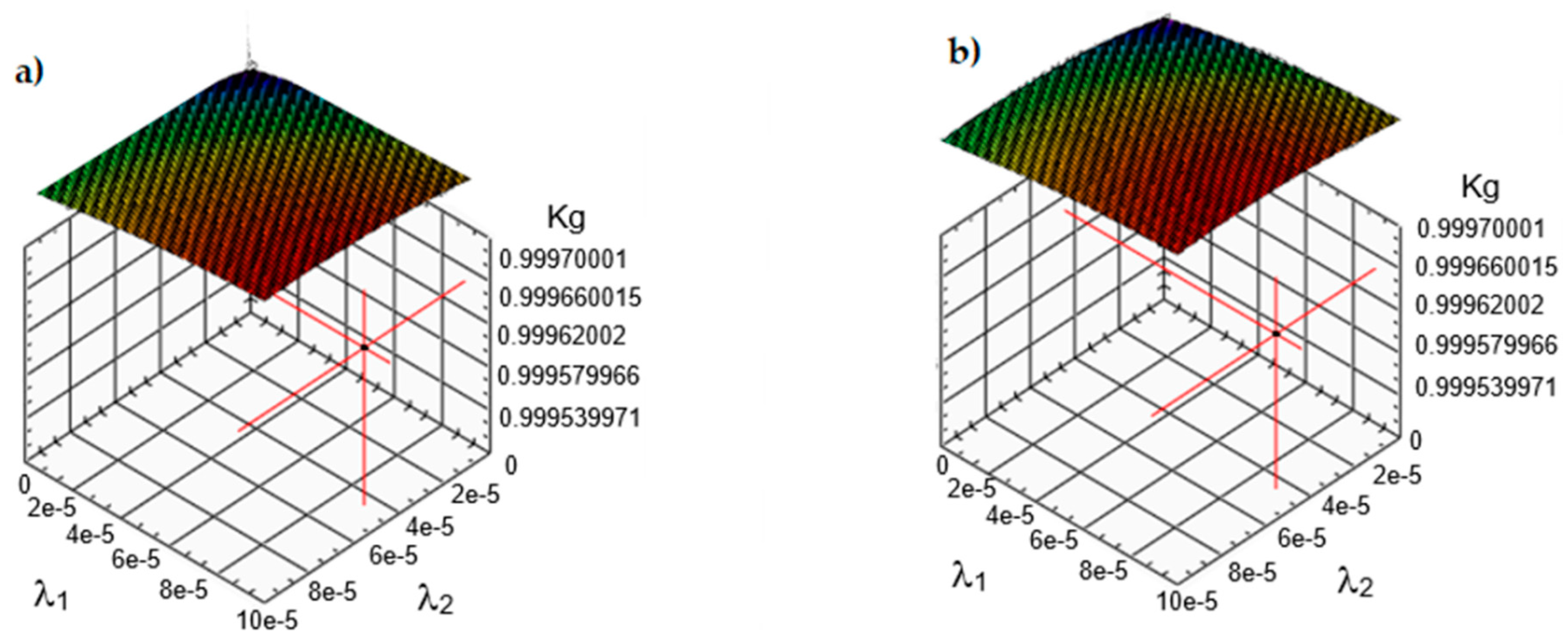
Figure 9.
Graphs of the test of the mean time between successive failures, for constant parameters, including: mean repair time 0.7 [h]; mean operating time I type 0.8 [h]; type II mean service time = 1.3 [h], where: (a) the mean time between successive failures is 1000 [h]; (b) the mean time between successive failures is 1200 [h].

Figure 10.
Graphs of the test of the mean time between successive failures, for constant parameters, including: mean repair time 0.7 [h]; mean operating time I type 0.8 [h]; type II mean service time = 1.3 [h], where: (a) the mean time between successive failures is 1300 [h]; (b) the mean time between successive failures is 1500 [h].

Figure 11.
Graphs of the test of the mean time between successive failures, for constant parameters, including: mean repair time 0.7 [h]; mean operating time I type 0.8 [h]; type II mean service time = 1.3 [h], where: (a) the mean time between successive failures is 1800 [h]; (b) the mean time between failures is 2000 [h].

Figure 12.
Graphs of the test of the mean time between successive failures, for constant parameters, including: mean repair time 0.7 [h]; mean operating time I type 0.8 [h]); type II mean service time = 1.3 [h], where: (a) the mean time between successive failures is 2500 [h]; (b) the mean time between successive failures is 3000 [h].

Figure 13.
Graph of the reliability of wind farm devices in the operation process as a function of the time between successive failures.
Figure 13.
Graph of the reliability of wind farm devices in the operation process as a function of the time between successive failures.


Table 1.
Max. value readiness factor Kg.
| Average Repair Time | Value Max. Readiness Factor Kg |
|---|---|
| 0.3 | 0.999793711044 |
| 0.4 | 0.998742403291 |
| 0.5 | 0.987682914322 |
| 0.6 | 0.985590024178 |
| 0.7 | 0.974590023678 |
| 0.8 | 0.969544193147 |
| 0.9 | 0.969488234806 |
| 1.0 | 0.959435172789 |
Table 2.
Max. value readiness factor Kg.
| Mean Time between Successive Failures (h) | Value of Max. Readiness Factor Kg |
|---|---|
| 1000 | 0.999427552702 |
| 1200 | 0.989498551118 |
| 1300 | 0.979567543594 |
| 1500 | 0.969612736465 |
| 1800 | 0.959688899662 |
| 2000 | 0.959728217231 |
| 2500 | 0.949782318116 |
| 3000 | 0.949815173253 |
Publisher’s Note: MDPI stays neutral with regard to jurisdictional claims in published maps and institutional affiliations. |
© 2022 by the authors. Licensee MDPI, Basel, Switzerland. This article is an open access article distributed under the terms and conditions of the Creative Commons Attribution (CC BY) license (https://creativecommons.org/licenses/by/4.0/).
Share and Cite
MDPI and ACS Style
Duer, S.; Paś, J.; Hapka, A.; Duer, R.; Ostrowski, A.; Woźniak, M. Assessment of the Reliability of Wind Farm Devices in the Operation Process. Energies 2022, 15, 3860. https://0-doi-org.brum.beds.ac.uk/10.3390/en15113860
AMA Style
Duer S, Paś J, Hapka A, Duer R, Ostrowski A, Woźniak M. Assessment of the Reliability of Wind Farm Devices in the Operation Process. Energies. 2022; 15(11):3860. https://0-doi-org.brum.beds.ac.uk/10.3390/en15113860
Chicago/Turabian StyleDuer, Stanisław, Jacek Paś, Aneta Hapka, Radosław Duer, Arkadiusz Ostrowski, and Marek Woźniak. 2022. "Assessment of the Reliability of Wind Farm Devices in the Operation Process" Energies 15, no. 11: 3860. https://0-doi-org.brum.beds.ac.uk/10.3390/en15113860
Note that from the first issue of 2016, this journal uses article numbers instead of page numbers. See further details here.