
Modal Analysis of a Lithium-Ion Battery for Electric Vehicles
by
 ,
,
Nicholas Gordon Garafolo
*, 
Siamak Farhad
*,
Manindra Varma Koricherla
,
Shihao Wen
and
Roja Esmaeeli
Department of Mechanical Engineering, University of Akron, Akron, OH 44325, USA
*
Authors to whom correspondence should be addressed.
Energies 2022, 15(13), 4841; https://0-doi-org.brum.beds.ac.uk/10.3390/en15134841
Submission received: 9 June 2022
/
Revised: 21 June 2022
/
Accepted: 22 June 2022
/
Published: 1 July 2022
(This article belongs to the Special Issue Lithium-Ion Batteries: Latest Advances, Challenges and Prospects)
Abstract
:The battery pack in electric vehicles is subjected to road-induced vibration and this vibration is one of the potential causes of battery pack failure, especially once the road-induced frequency is close to the natural frequency of the battery when resonance occurs in the cells. If resonance occurs, it may cause notable structural damage and deformation of cells in the battery pack. In this study, the natural frequencies and mode shapes of a commercial pouch lithium-ion battery (LIB) are investigated experimentally using a laser scanning vibrometer, and the effects of the battery supporting methods in the battery pack are presented. For this purpose, a test setup to hold the LIB on the shaker is designed. A numerical analysis using COMSOL Multiphysics software is performed to confirm that the natural frequency of the designed test setup is much higher than that of the battery cell. The experimental results show that the first natural frequency in the two-side supported and three-side supported battery is about 310 Hz and 470 Hz, respectively. Although these frequencies are more than the road-induced vibration frequencies, it is recommended that the pouch LIBs are supported from three sides in battery packs. The voltage of the LIB is also monitored during all experiments. It is observed that the battery voltage is not affected by applying mechanical vibration to the battery.
1. Introduction
Relatively high energy and power densities, long cycle life, lightweight design, and the absence of memory effect have facilitated lithium-ion batteries (LIBs) have expanded in use as a sustainable product for supplying electrical energy [1,2,3]. The use of LIBs in electric vehicles (EVs) and hybrid electric vehicles (HEVs) is also becoming more attractive to automobile manufacturers. LIBs are preferred over other battery technologies for EVs and HEVs due to their higher energy and power densities. At present, substantial research and development efforts are being focused on increasing the range of applications of LIBs in EVs and HEVs.
The study of vibration and impact loads of LIBs and their casing is of great importance to avoid their malfunctioning in EV and HEV operations, which has led to commitments from researchers to study the behavior of LIBs under such conditions. Concerning the safety of the vehicle and, consequently, its passengers, the probability of short circuit or thermal runaway, or explosion in its worst-case, shall be studied thoroughly. Consequently, a lot of researchers have done studies on quantifying the mechanical robustness of the cell and investigating, for instance, the effect of nail penetration [4], the mechanical crushing of the cell [5,6,7], the durability of the cell under impact [5,6,7,8], mechanical shock [5] and fatigue conditions of the battery system under extreme temperature and pressure conditions [9,10]. These are done to satisfy the requirements of the whole vehicle crash homologation standards which are reviewed specifically for the use of LIBs in transportation by Refs. [11,12,13]. In addition, some researchers examined battery shell casing properties for cylindrical LIBs for the EV crash [5], and performed axial and lateral compression tests, three points bend tests, and hydraulic tests [14]. Furthermore, the battery brackets are studied by a means of single-axis acceleration test approach [15]. Therefore, conducting investigations on the amplitude and frequency of the vibration to which batteries are exposed is vital to understanding how the mechanical vibration affects electronic and electrical components and how to avoid or hinder the loss of electrical continuity and the housing structural failure, which is a common well-known cause of failure [15,16,17,18,19]. It has been demonstrated that structural failure with sustained and excessive motion inevitably happens if a system vibration happens at the same frequency as its natural frequency [16]. Some studies are dedicated to studying individual single-cell responses to vibration while some referred to considering the whole battery pack. Choi et al. [20], investigated the natural frequencies of a used but serviceable 10 Ah LIB pouch cell during impact hammer and shaker excitation tests. The results of this study showed that the first and second mode shape frequencies of the battery to the impact hammer testing are roughly 267 Hz and 474 Hz, respectively. For the frequency response of the battery for the white noise wave to the shaker, with two-edge clamping condition along the out-of-plane excitation, the first and second mode shapes are around 87 Hz and 478 Hz, respectively. Similarly, Hoopen and James [17] studied impulse excitation provided by an impact hammer to quantify the natural frequencies and mode shapes of a commercially available 25 Ah Nickel Manganese Cobalt Oxide (NMC) laminate pouch cell. However, compared to Choi et al.’s study, they covered the calculation of the values of cell damping and stiffness and reported that the lowest natural frequency of the cell is about 200 Hz [20].
There are three methods of excitations commonly employed to measure the modal response of a structure: impulse excitation, dynamic excitation, and operational excitation [21]. The impulse excitation is implemented using a hammer applying the impact testing. This method is commonly employed when the testing of specific points is aimed. However, the destruction of the structure during the test should be considered. In operational excitation, the structure is subjected to the real-life application and it is done after the structure is subjected to impulse and dynamic excitation and acts as a final verification test [21]. However, the low accuracy of the operational excitement to measure the natural frequency of a battery system in EVs or HEVs is its main drawback. Dynamic excitation is often employed for structures for which performing the other two methods is not applicable, since they are destructive testing. The way that dynamic excitation is employed is to use an electromagnetic shaker or hydraulic shaker to apply a force or frequency input that is known to the structure. The flexibility that dynamic excitation offers is that researchers can apply different values of inputs conveniently, such as specific force and specific frequency [21].
The study of the vehicle vibration inputs to the batteries suggests testing EV and HEV battery vibrational characteristics over the range of 0 Hz to 150 Hz frequency [17]. In addition, standards and regulations recommend testing in the range of 7–200 Hz, 7–50 Hz, and 10–190 Hz for the regulation UN38.3 [22], regulation ECE 100 [23] and the SAE J2380 standard [24], respectively. Consequently, when the natural frequency of the battery and the support are beyond 200 Hz the battery may not experience the failure due to vibration. This paper suggests an experimental method to quantify a commercial LIB’s natural frequencies and mode shapes. The laser scanning vibrometer is used for modal analysis with frequency response functions (FRF). The design of the battery holder to test the battery in supporting configurations of two-side and three-side clamping is presented. The effect of the battery on the LIB voltage fluctuation is also studied.
2. Formulations
COMSOL Multiphysics software is employed to calculate the natural frequency of the base-plate design and to ensure that it does not coincide with the natural frequency of the battery and the excitation frequency. The un-damped free vibration equation for the system is as follows:
where, M is the mass matrix, is the mass acceleration vectors, is the stiffness matrix, and X is the displacement vectors of the modes. In a natural mode of vibration, the displacement of each mode is calculated by:
where, ω and are the angular frequency and phase angle of the ith mode. is the matrix of the displacement of the modes, and is the vector of maximum values. If the displacement field of the given structure is harmonic, the Eigen frequency can be derived. Dictating equations in the study are in terms of the excitation load.
where, ρ is the density of the material, ω is the angular frequency of the excitation load, and u is the harmonic response from the structure. The Eigenvalues λ and the Eigen frequencies f are calculated using Equation (4):
where, the eigenvalue is .
3. Experimental
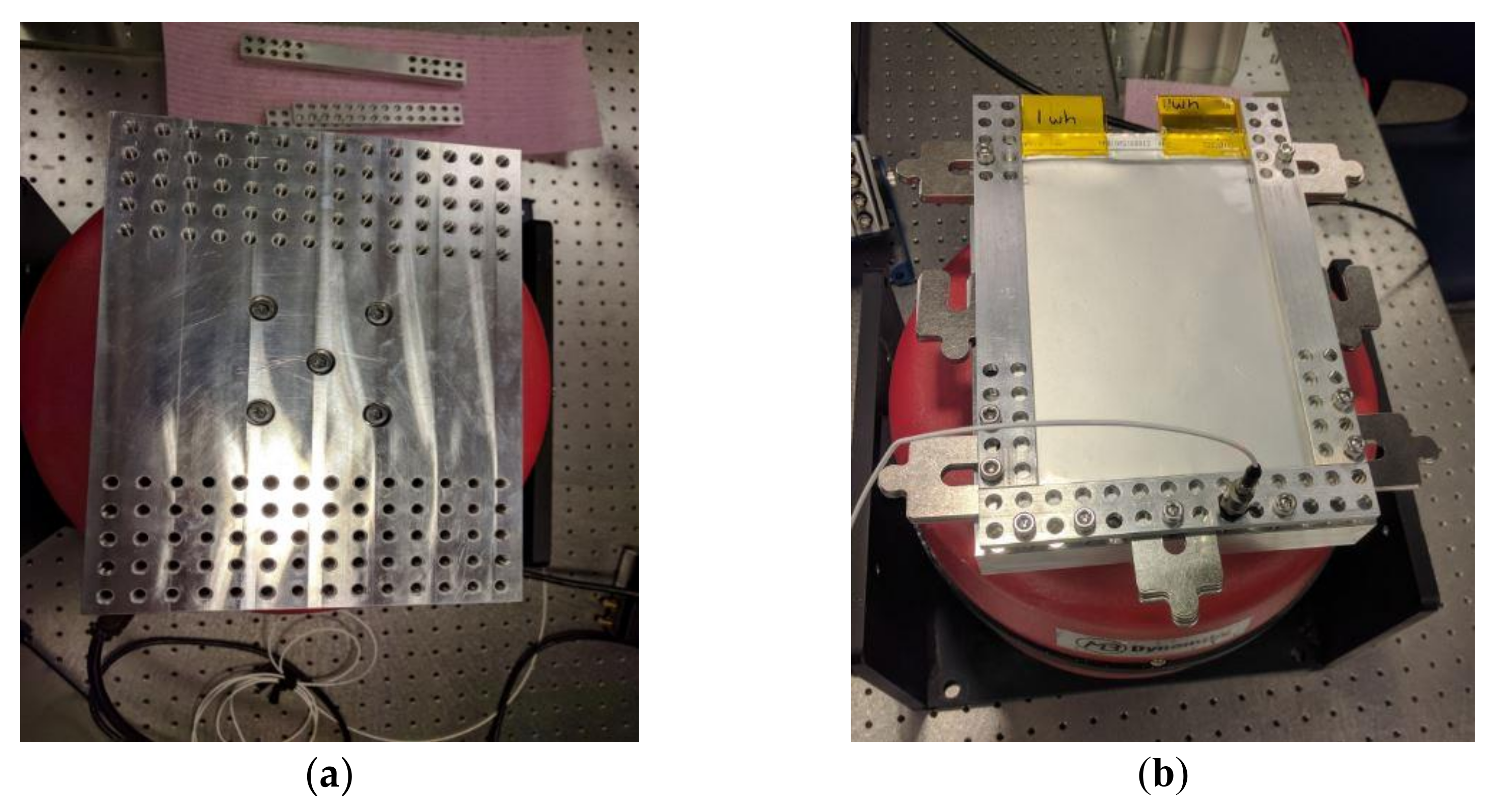
The design of the test apparatus is done by SolidWorks software, where the LIB is held on the shaker and the baseplate is designed in a way to accommodate the geometry of the battery. To replicate the real-life mounting conditions of the battery, the baseplate aims to provide rigid support to the battery and hold the battery firmly. The baseplate is designed such that the battery fits in easily and the fixture including the battery does not exceed the weight-bearing limit of the shaker. The material used for the baseplate is 6061 Aluminum and its geometry is presented in Figure 1. The baseplate is mounted on the shaker using M6 screws to the center of the shaker and is torqued down with 45 lb/in. Then, the battery is fixed on that plate with clips. To perform sinusoidal frequency sweeps, a 110 lb MB RED dynamic shaker is used. A signal generator is used to create input variables. The shaker specifications are listed in Table 1. Due to restrictions of weight that the dynamic shaker aperture load is 12 lb and the maximum weight of the apparatus that the aperture arm of the shaker can handle is 11 lb, the weight of the fixture and apparatus including the battery is determined to be 10 lb. At the test of the structure mounted aperture arm, the dynamic shaker delivers low noise motion. The casing material used all around the flexures to hold the internal components is stainless steel. Using a set of ultra-flexible multi-strand wire, coil currents are conducted to the coil from which the shaker receives the signal and responds accordingly. The cooling system is provided with a constant field and eliminates the need for a power source. The reason for using a cooling system is to reduce the resistive losses of the electromagnet from coil overheating and abate the breakdown of the coil insulation [25]. The baseplate is then installed onto the aperture arm of the shaker. The completed experimental setup with the battery is presented in Figure 2.
A commercially available aftermarket pouch LIB consisting of 23 individual cells that are sandwiched together, with the specifications listed in Table 2, is used. We choose the pouch type for the LIB because it is getting more attraction for automobile applications or heavy-duty vehicles.
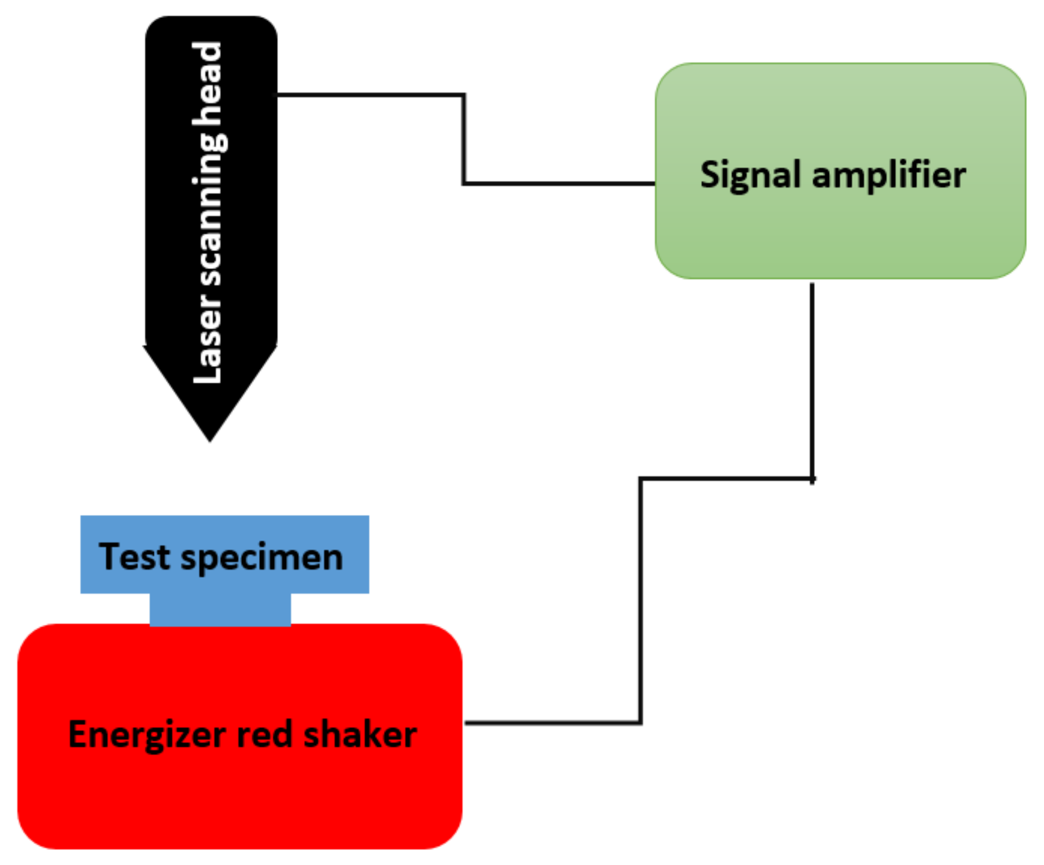
The velocity of the battery is directly measured with a Polytec PSV 400 laser scanner and the velocity data is converted to FRF calculations using integrated laser vibrometer software. For conducting calculations of the frequency response function, there is a built-in accelerometer that is attached to the surface of the dynamic shaker. The experimental setup block diagram is shown in Figure 3.
3.1. Boundary Conditions
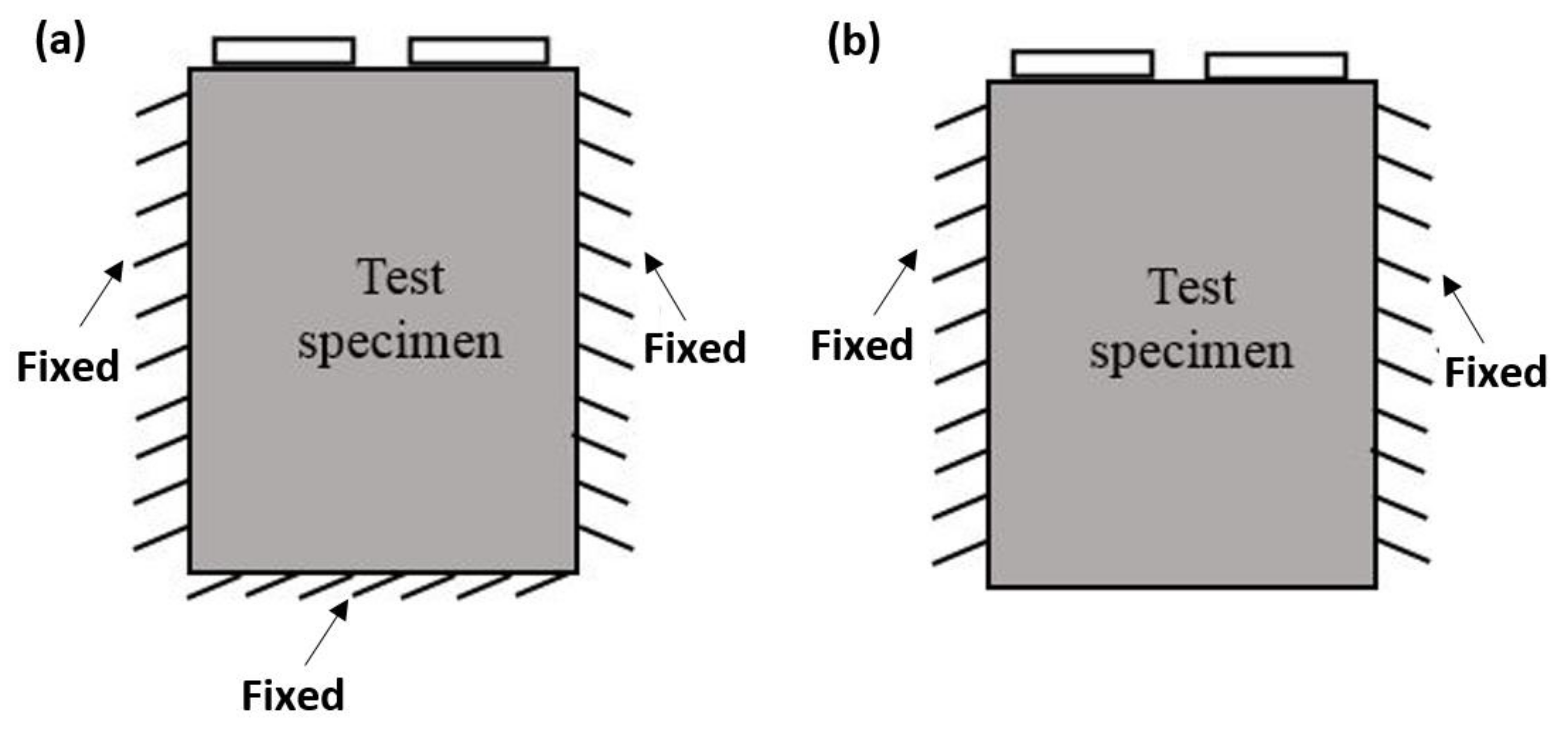
To set up the system to represent real conditions of a battery in EVs/HEVs, two different boundary conditions are examined. Boundary condition 1 is the rigidly clamped mounting technique that fixes the three sides of the battery as shown in Figure 4a. Boundary condition 2 is the partially clamped mounting technique which can be seen in Figure 4b. This boundary condition leaves the output of the battery and the opposite side open and clamped rigidly lengthwise.
3.2. Grid Convergence
A study on grid convergence is necessary since grid densities of a scanning laser vibrometer should not have any effect on the experiments. Three different grid sizes from widely-placed to closely-placed grid points are shown in Table 3. The results from the grid convergence study in Figure 5 show that the mode shapes resulting from boundary condition 1 are consistent with the increase of scanning laser vibrometer grid densities. The scanning time of each grid size, as shown in Table 3, takes more time with an increase of grid densities. Finally, based on the results from the mode shapes and duration of the scan, evenly placed grid size mesh 2 with 425 points is chosen for the rest of the study.
4. Results and Discussion
4.1. Baseplate
The action to take into consideration is to ensure that the natural frequencies of the baseplate and the battery do not happen at an equal frequency. Otherwise, this might lead to misinterpretation of the results because of the resonance that the whole apparatus will face. To verify this, an Eigen frequency study with the use of COMSOL Multiphysics software is done on the baseplate. Figure 6 shows the first mode shape of the baseplate. By gradually increasing the frequency input to the structure, there will be other natural frequencies shown by it, as presented in Table 4.
The first natural frequency of the baseplate, which is the frequency in which the first bending of the structure occurs, happens at 2716.3 Hz, while the first natural frequency of the LIB is reported to be lower than 200 Hz [17,20]. Consequently, there is no match between the natural frequency of the baseplate and the battery, which means that the whole apparatus will not resonate at the same natural frequency.
4.2. Battery Mode Shapes
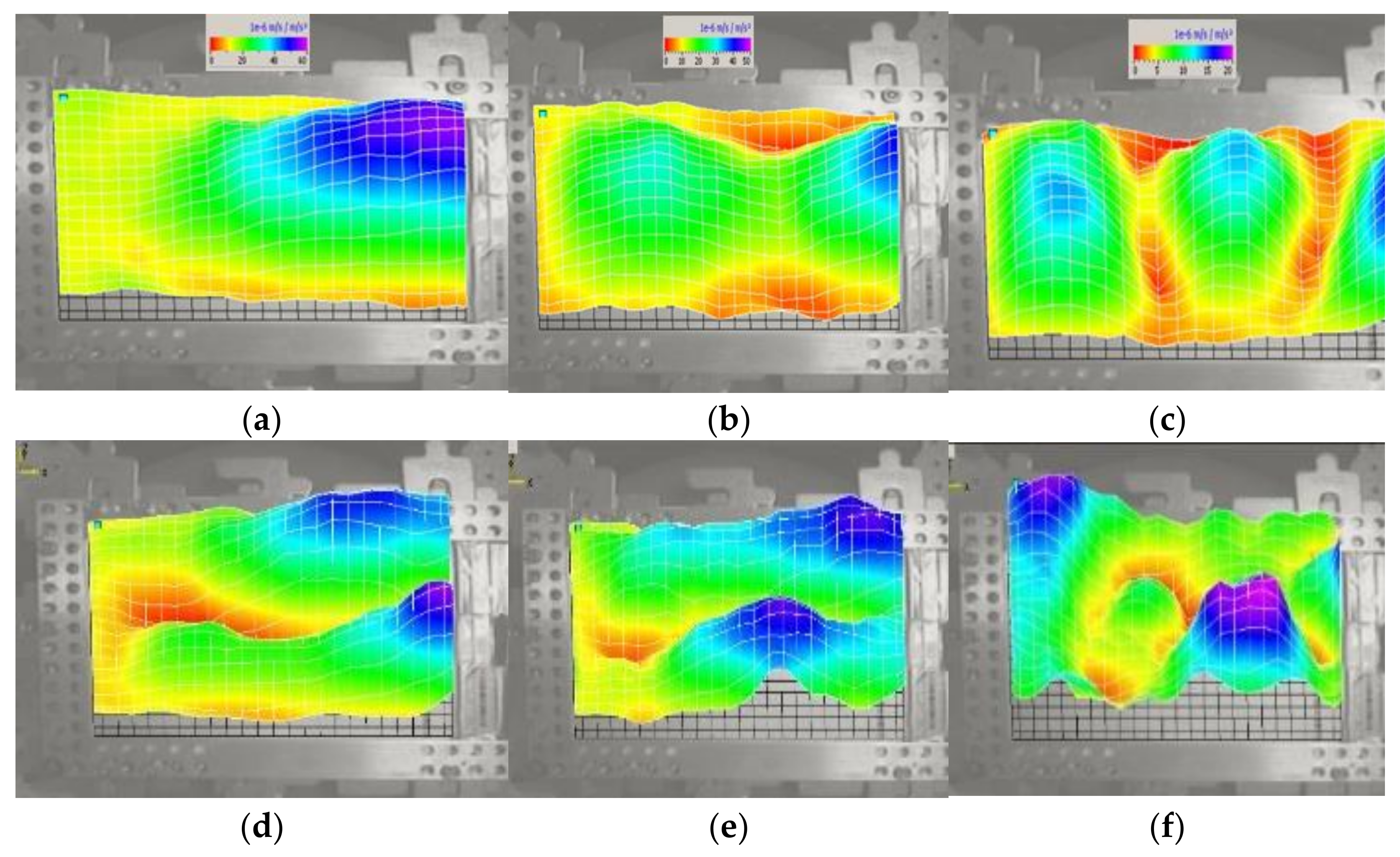
In Figure 7 and Figure 8, the magnitude of mode shapes for boundary conditions 1 and 2 are shown. A range of 470–1060 Hz for the first six natural frequencies for boundary condition 1 is seen, while for boundary condition 2 the range of 310–995 Hz for the first six natural frequencies is observed. However, the vibration induced by the road does not exceed 200 Hz, which is far below the ranges discussed above. Consequently, it is unlikely that the natural frequencies coincide with road-induced vibrations. Thus, both stacking techniques can be implemented.
The change in battery voltage is monitored during the vibration test. By measurement of the battery voltage in different time intervals, it is revealed that the battery voltage remains at 3.287 V with no significant fluctuation. Finally, after performing a complete test for both boundary conditions, no battery failure is observed.
4.3. Repeatability Analysis
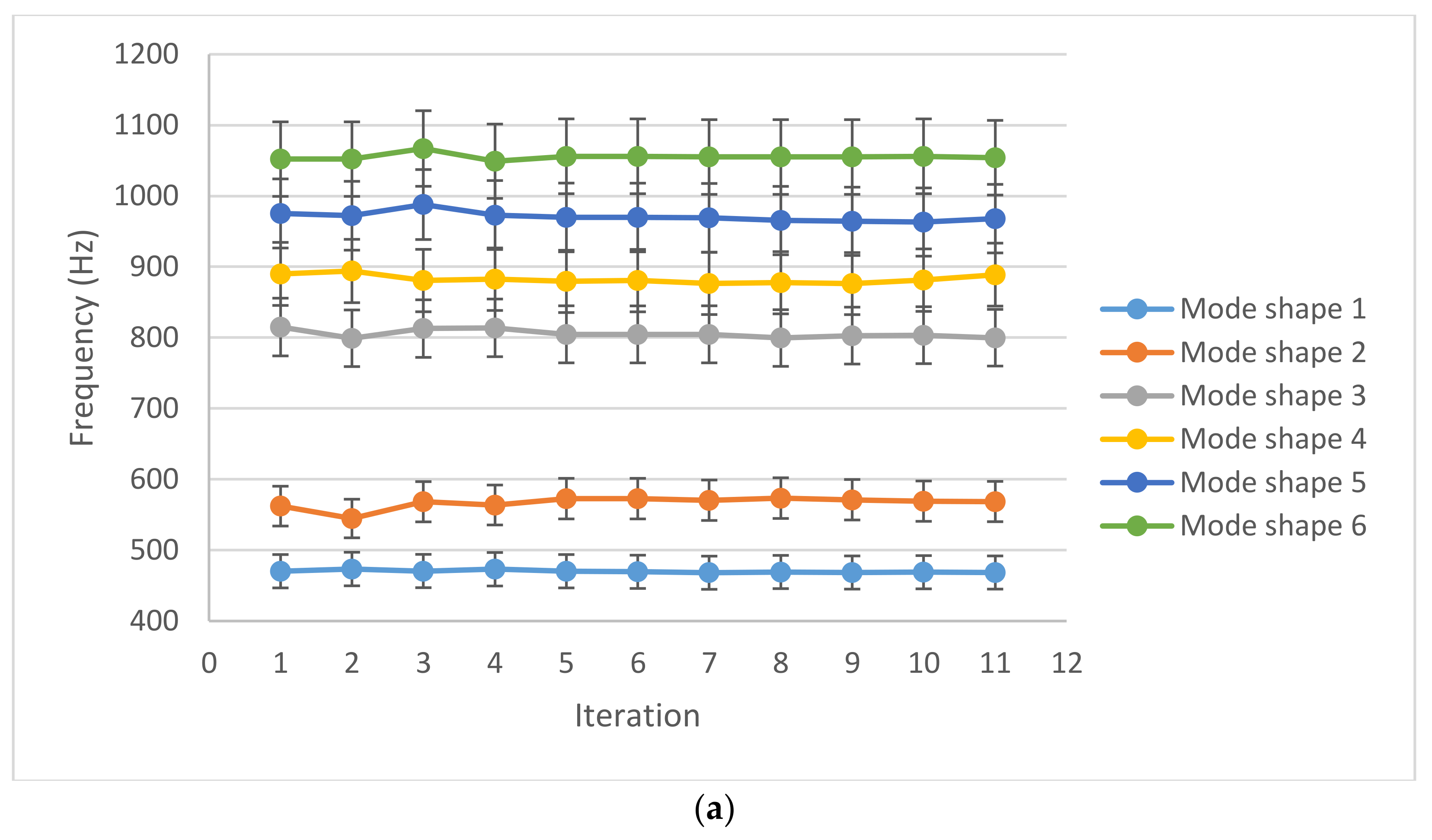
To ensure the reliability of the frequency results and the mode shapes, a repeatability study with a sample size of 11 is done. A break is given to the test apparatus after each test. To cover all mode shapes a wide frequency range of 200–2000 Hz is chosen. The results of repeatability test runs are presented in Figure 9 for boundary conditions 1 and 2, which show that there is no significant deviation of the observed frequencies.
5. Conclusions
The battery installed in EVs and HEVs is subjected to continuous vibration caused by road conditions. If the frequency of the road-induced vibration matches the natural frequency of the battery pack, there may be a failure in the battery due to the created resonance. In this paper we studied the mode shapes and natural frequencies of a commercially available pouch LIB, designed for EVs and HEVs. The LIB was excited by a dynamic shaker and the study was done using a laser scanning vibrometer. Two battery boundary conditions of the fixed-fixed-fixed-free (boundary condition 1) and the fixed-free-fixed-free (boundary condition 2) were examined. These two boundary conditions simulated the battery installation conditions in EVs/HEVs’ battery packs. The repeatability tests and grid convergence studies were performed to ensure the accuracy and reliability of test results. The results revealed that the frequencies of the first six mode shapes of the battery fall within the range of 460–1070 Hz and 310–1000 Hz for boundary conditions 1 and 2, respectively. Although a change in boundary condition will alter the natural frequency of the battery, in either of the boundary conditions the natural frequency of the battery does not coincide with the road-induced vibration, which is lower than 200 Hz. The battery voltage was also monitored during the vibration tests. It was revealed that applying vibration with frequencies lower than the resonance frequencies will not affect the battery voltage. The results presented in this paper is for a pouch LIB with liquid electrolyte and the graphite anode and LFP cathode active materials. A separate study may be required to prove that the results of this paper can be generalized for LIBs with different designs and different electrode active materials and electrolytes.
Author Contributions
Data curation, M.V.K.; Formal analysis, N.G.G., S.F., M.V.K., S.W. and R.E.; Funding acquisition, N.G.G. and S.F.; Investigation, N.G.G., M.V.K. and R.E.; Methodology, N.G.G. and S.F.; Software, S.F.; Supervision, N.G.G. and S.F.; Writing—original draft, M.V.K., S.W. and R.E.; Writing—review & editing, N.G.G. and S.F. All authors have read and agreed to the published version of the manuscript.
Funding
This research received no external funding.
Institutional Review Board Statement
Not applicable.
Informed Consent Statement
Not applicable.
Data Availability Statement
Not applicable.
Acknowledgments
The financial support of the University of Akron is highly appreciated.
Conflicts of Interest
The authors declare no conflict of interest.
References
- Foreman, E.; Zakri, W.; Sanatimoghaddam, M.H.; Modjtahedi, A.; Pathak, S.; Kashkooli, A.G.; Garafolo, N.G.; Farhad, S. A review of inactive materials and components of flexible lithium-ion batteries. Adv. Sustain. Syst. 2017, 1, 1700061. [Google Scholar] [CrossRef]
- Iordache, A.; Bresser, D.; Solan, S.; Retegan, M.; Bardet, M.; Skrzypski, J.; Picard, L.; Dubois, L.; Gutel, T. From an enhanced understanding to commercially viable electrodes: The case of PTCLi4 as sustainable organic lithium-ion anode material. Adv. Sustain. Syst. 2017, 1, 1600032. [Google Scholar] [CrossRef]
- Sasi, R.; Chandrasekhar, B.; Kalaiselvi, N.; Devaki, S.J. Green solid ionic liquid crystalline electrolyte membranes with anisotropic channels for efficient li-ion batteries. Adv. Sustain. Syst. 2017, 1, 1600031. [Google Scholar] [CrossRef]
- Feng, X.; Sun, J.; Ouyang, M.; Wang, F.; He, X.; Lu, L.; Peng, H. Characterization of penetration induced thermal runaway propagation process within a large format lithium ion battery module. J. Power Sources 2014, 275, 261–273. [Google Scholar] [CrossRef]
- Avdeev, I.; Gilaki, M. Structural analysis and experimental characterization of cylindrical lithium-ion battery cells subject to lateral impact. J. Power Sources 2014, 271, 382–391. [Google Scholar] [CrossRef]
- Greve, L.; Fehrenbach, C. Mechanical testing and macro-mechanical finite element simulation of the deformation, fracture, and short circuit initiation of cylindrical Lithium-ion battery cells. J. Power Sources 2012, 214, 377–385. [Google Scholar] [CrossRef]
- Sahraei, E.; Meier, J.; Wierzbicki, T. Characterizing and modeling mechanical properties and onset of short circuit for three types of lithium-ion pouch cells. J. Power Sources 2014, 247, 503–516. [Google Scholar] [CrossRef]
- Shi, F.; Yu, H.; Chen, X.; Cui, T.; Zhao, H.; Shi, X. Mechanical performance study of lithium-ion battery module under dynamic impact test. In Proceedings of the 19th Asia Pacific Automotive Engineering Conference & SAE-China Congress 2017: Selected Papers; Springer: Singapore, 2019; pp. 1–11. [Google Scholar]
- Spinner, N.S.; Field, C.R.; Hammond, M.H.; Williams, B.A.; Myers, K.M.; Lubrano, A.L.; Rose-Pehrsson, S.L.; Tuttle, S.G. Physical and chemical analysis of lithium-ion battery cell-to-cell failure events inside custom fire chamber. J. Power Sources 2015, 279, 713–721. [Google Scholar] [CrossRef]
- Liu, X.; Stoliarov, S.I.; Denlinger, M.; Masias, A.; Snyder, K. Comprehensive calorimetry of the thermally-induced failure of a lithium ion battery. J. Power Sources 2015, 280, 516–525. [Google Scholar] [CrossRef]
- Huo, H.; Xing, Y.; Pecht, M.; Züger, B.J.; Khare, N.; Vezzini, A. Safety requirements for transportation of lithium batteries. Energies 2017, 10, 793. [Google Scholar] [CrossRef]
- Farrington, M.D. Safety of lithium batteries in transportation. J. Power Sources 2001, 96, 260–265. [Google Scholar] [CrossRef]
- Ruiz, V.; Pfrang, A.; Kriston, A.; Omar, N.; van den Bossche, P.; Boon-Brett, L. A review of international abuse testing standards and regulations for lithium ion batteries in electric and hybrid electric vehicles. Renew. Sustain. Energy Rev. 2018, 81, 1427–1452. [Google Scholar] [CrossRef]
- Zhang, X.; Wierzbicki, T. Characterization of plasticity and fracture of shell casing of lithium-ion cylindrical battery. J. Power Sources 2015, 280, 47–56. [Google Scholar] [CrossRef]
- Choi, Y.; Jung, D.; Ham, K.; Bae, S. A study on the accelerated vibration endurance tests for battery fixing bracket in electrically driven vehicles. Procedia Eng. 2011, 10, 851–856. [Google Scholar] [CrossRef] [Green Version]
- Moon, S.-I.; Cho, I.-J.; Yoon, D. Fatigue life evaluation of mechanical components using vibration fatigue analysis technique. J. Mech. Sci. Technol. 2011, 25, 631–637. [Google Scholar] [CrossRef]
- Hooper, J.M.; Marco, J. Experimental modal analysis of lithium-ion pouch cells. J. Power Sources 2015, 285, 247–259. [Google Scholar] [CrossRef] [Green Version]
- Hooper, J.M.; Marco, J. Characterising the in-vehicle vibration inputs to the high voltage battery of an electric vehicle. J. Power Sources 2014, 245, 510–519. [Google Scholar] [CrossRef]
- Hooper, J.M.; Marco, J.; Chouchelamane, G.H.; Chevalier, J.S.; Williams, D. Multi-axis vibration durability testing of lithium-ion 18650 NCA cylindrical cells. J. Energy Storage 2018, 15, 103–123. [Google Scholar] [CrossRef]
- Choi, H.Y.; Lee, I.; Lee, J.S.; Kim, Y.M.; Kim, H. A study on mechanical characteristics of lithium-polymer pouch cell battery for electric vehicle. In Proceedings of the 23rd International Technical Conference on the Enhanced Safety of Vehicles (ESV) National Highway Traffic Safety Administration, Seoul, Korea, 27–30 May 2013. [Google Scholar]
- Ewins, D.J. Basics and state-of-the-art of modal testing. Sadhana 2000, 25, 207–220. [Google Scholar] [CrossRef] [Green Version]
- Available online: www.mtixtl.com/UN38.3/UN_Test_Manual_Lithium_Battery_Requirements.PDF (accessed on 23 June 2022).
- Available online: https://unece.org/fileadmin/DAM/trans/main/wp29/wp29regs/2013/R100r2e.pdf (accessed on 23 June 2022).
- Available online: www.sae.org/standards/content/j2380_201312/ (accessed on 23 June 2022).
- User Manual of Red Energizer, MB Dynamics. Available online: https://www.mbdynamics.com/wp-content/uploads/2018/10/MB-BSR-ENRGZR-RED-1018-FINAL.pdf (accessed on 23 June 2022).
Figure 1.
Drawing of the plate in SolidWorks Software.

Figure 2.
(a) Baseplate installed onto the aperture arm of the shaker, (b) Complete experimental setup with the pouch LIB.
Figure 2.
(a) Baseplate installed onto the aperture arm of the shaker, (b) Complete experimental setup with the pouch LIB.

Figure 3.
Block diagram of the experimental setup.

Figure 4.
Battery Boundary conditions (a) Boundary condition 1, which is the three-side clamped, and (b) Boundary condition 2, which is the two-side clamped.
Figure 4.
Battery Boundary conditions (a) Boundary condition 1, which is the three-side clamped, and (b) Boundary condition 2, which is the two-side clamped.

Figure 5.
Each mode shape frequency for the three mesh sizes.

Figure 6.
The first mode shape of the baseplate happens at 2716.3 Hz.

Figure 7.
Pouch LIB mode shapes for boundary condition 1 shown in Figure 4a. (a) mode shape 1–first bending, (b) mode shape 2–first torsion, (c) mode shape 3–second torsion, (d) mode shape 4–second bending, (e) mode shape 5–third bending, (f) mode shape 6–third torsion.
Figure 7.
Pouch LIB mode shapes for boundary condition 1 shown in Figure 4a. (a) mode shape 1–first bending, (b) mode shape 2–first torsion, (c) mode shape 3–second torsion, (d) mode shape 4–second bending, (e) mode shape 5–third bending, (f) mode shape 6–third torsion.

Figure 8.
LIB mode shapes in boundary condition 2 shown in Figure 4b. (a) mode shape 1–first bending, (b) mode shape 2–first torsion, (c) mode shape 3–second torsion, (d) mode shape 4–second bending, (e) mode shape 5–third bending, (f) mode shape 6–third torsion.
Figure 8.
LIB mode shapes in boundary condition 2 shown in Figure 4b. (a) mode shape 1–first bending, (b) mode shape 2–first torsion, (c) mode shape 3–second torsion, (d) mode shape 4–second bending, (e) mode shape 5–third bending, (f) mode shape 6–third torsion.


Figure 9.
Mode shapes frequency for 11 repetitions; (a) boundary condition 1, (b) boundary condition 2.
Figure 9.
Mode shapes frequency for 11 repetitions; (a) boundary condition 1, (b) boundary condition 2.


Table 1.
Specification of the energizer red shaker shown in Figure 2.
Table 1.
Specification of the energizer red shaker shown in Figure 2.
| Specifications | Value |
|---|---|
| Force output-cooling (convection) | 55 pounds (peak) |
| Stroke | 1.5 inch (peak-peak) |
| Distance between stops | 1.5 inch |
| Armature axial stiffness | 65 pounds/inch |
| Armature weight | 2.6 pounds |
| The frequency range of shaker | DC to 5000 Hz |
| Driver coil current | 22 Amperes Maximum |
| Driver coil DC resistance | 41 Ohms (@ amplifier connector on shaker) |
| Shaker attachments | Floor mount trunnion base |
| Dimensions | 13.1 in high (to top of mounting table) 14 in × 10.75 in footprint |
| Weight | 85 lbs. |
Table 2.
The specification of the aftermarket LIB used in this study.
| Item | Value |
|---|---|
| The thickness of copper current collector | 10 μm |
| The thickness of aluminum current collector | 20 μm |
| Thickness of anode | 57 μm |
| Thickness of cathode | 65 μm |
| Thickness of separator | 48 μm |
| Anode material | Graphite |
| Cathode material | Lithium iron phosphate, LiFePO4 (LFP) |
Table 3.
Mesh representation for the mesh size independency analysis.
| Mesh Number | Mesh Points | Mesh Representation | Scan Duration |
|---|---|---|---|
| Mesh 1 | 117 |  | 35 min |
| Mesh 2 | 425 |  | 1 h 25 min |
| Mesh 3 | 1247 |  | 6 h 20 min |
Table 4.
The first six natural frequencies of the baseplate.
| Frequency No. | Natural Frequency |
|---|---|
| 1 | 2716.3 Hz |
| 2 | 2999.0 Hz |
| 3 | 3013.8 Hz |
| 4 | 3118.5 Hz |
| 5 | 4247.1 Hz |
| 6 | 5398.7 Hz |
Publisher’s Note: MDPI stays neutral with regard to jurisdictional claims in published maps and institutional affiliations. |
© 2022 by the authors. Licensee MDPI, Basel, Switzerland. This article is an open access article distributed under the terms and conditions of the Creative Commons Attribution (CC BY) license (https://creativecommons.org/licenses/by/4.0/).
Share and Cite
MDPI and ACS Style
Garafolo, N.G.; Farhad, S.; Koricherla, M.V.; Wen, S.; Esmaeeli, R. Modal Analysis of a Lithium-Ion Battery for Electric Vehicles. Energies 2022, 15, 4841. https://0-doi-org.brum.beds.ac.uk/10.3390/en15134841
AMA Style
Garafolo NG, Farhad S, Koricherla MV, Wen S, Esmaeeli R. Modal Analysis of a Lithium-Ion Battery for Electric Vehicles. Energies. 2022; 15(13):4841. https://0-doi-org.brum.beds.ac.uk/10.3390/en15134841
Chicago/Turabian StyleGarafolo, Nicholas Gordon, Siamak Farhad, Manindra Varma Koricherla, Shihao Wen, and Roja Esmaeeli. 2022. "Modal Analysis of a Lithium-Ion Battery for Electric Vehicles" Energies 15, no. 13: 4841. https://0-doi-org.brum.beds.ac.uk/10.3390/en15134841
Note that from the first issue of 2016, this journal uses article numbers instead of page numbers. See further details here.