
Design of Damping Strategies for LC Filter Applied in Medium Voltage Variable Speed Drive †

 ,
,  , , , and
Abstract
:1. Introduction
2. Materials and Methods
2.1. LC Filter Design
2.2. Control Design
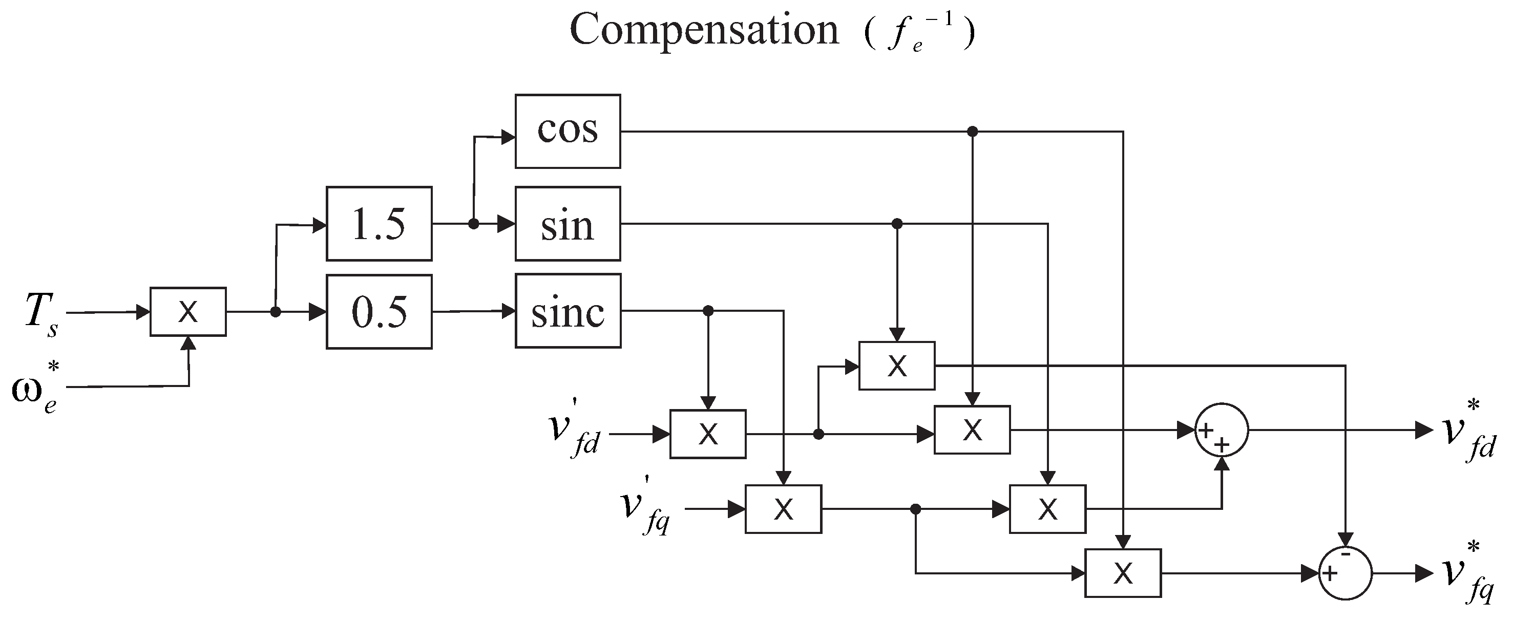
2.3. Delay Compensation
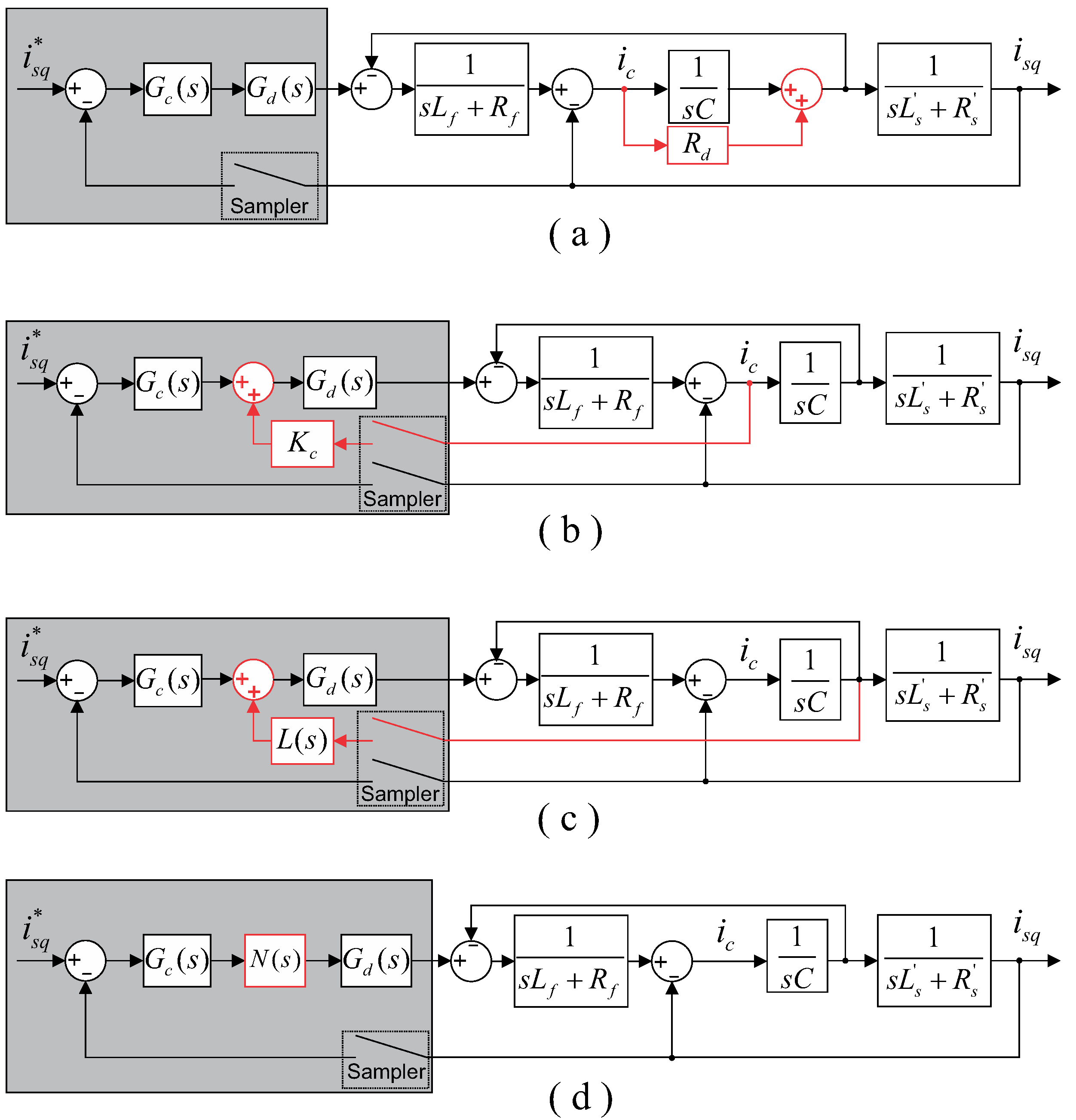
3. Damping Schemes
3.1. Passive Damping (PD)
3.2. Capacitor Current Feedback (CCF)
3.3. Capacitor Voltage Feedback (CVF)
3.4. Notch Filter (NF)
4. Case Study
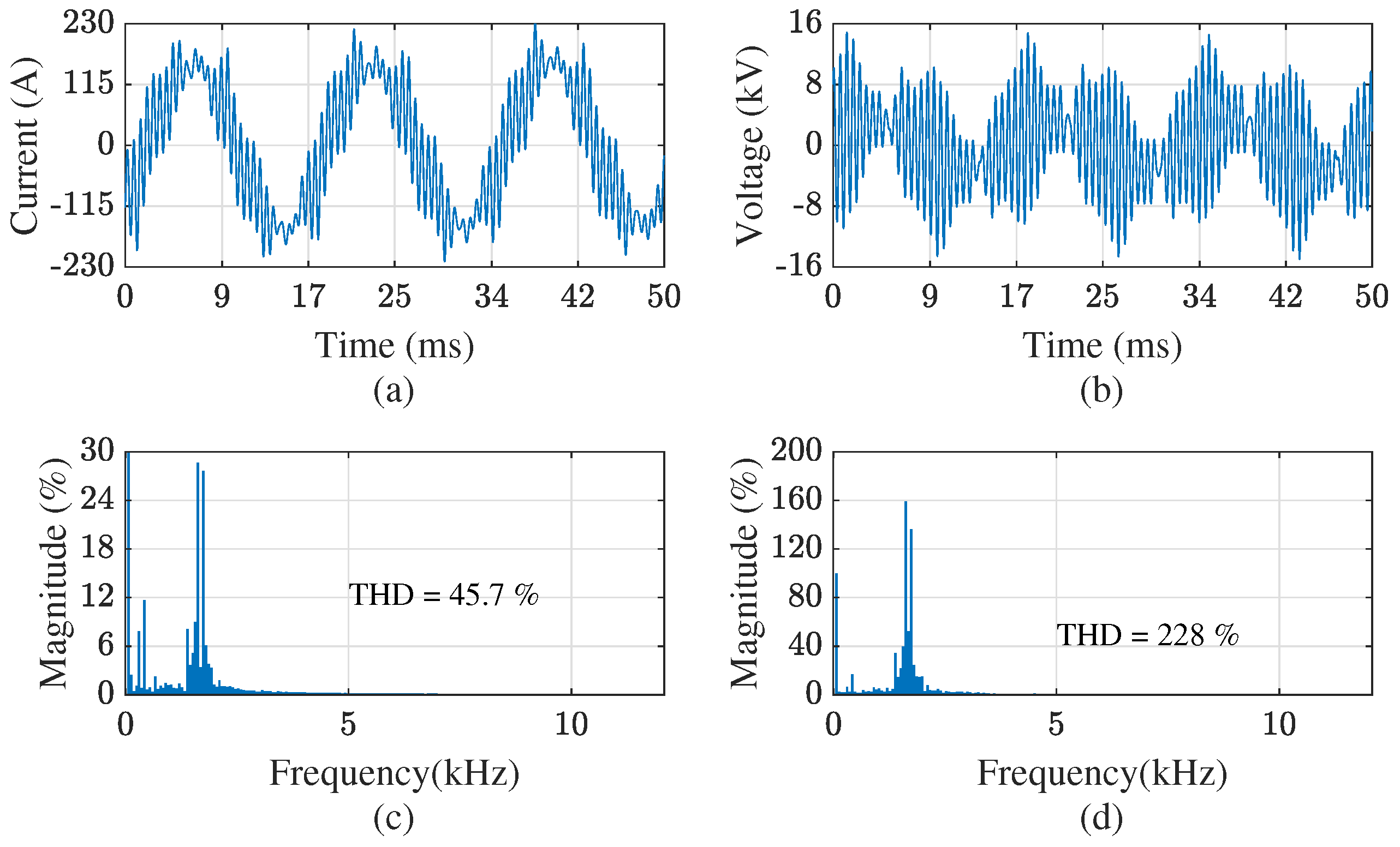
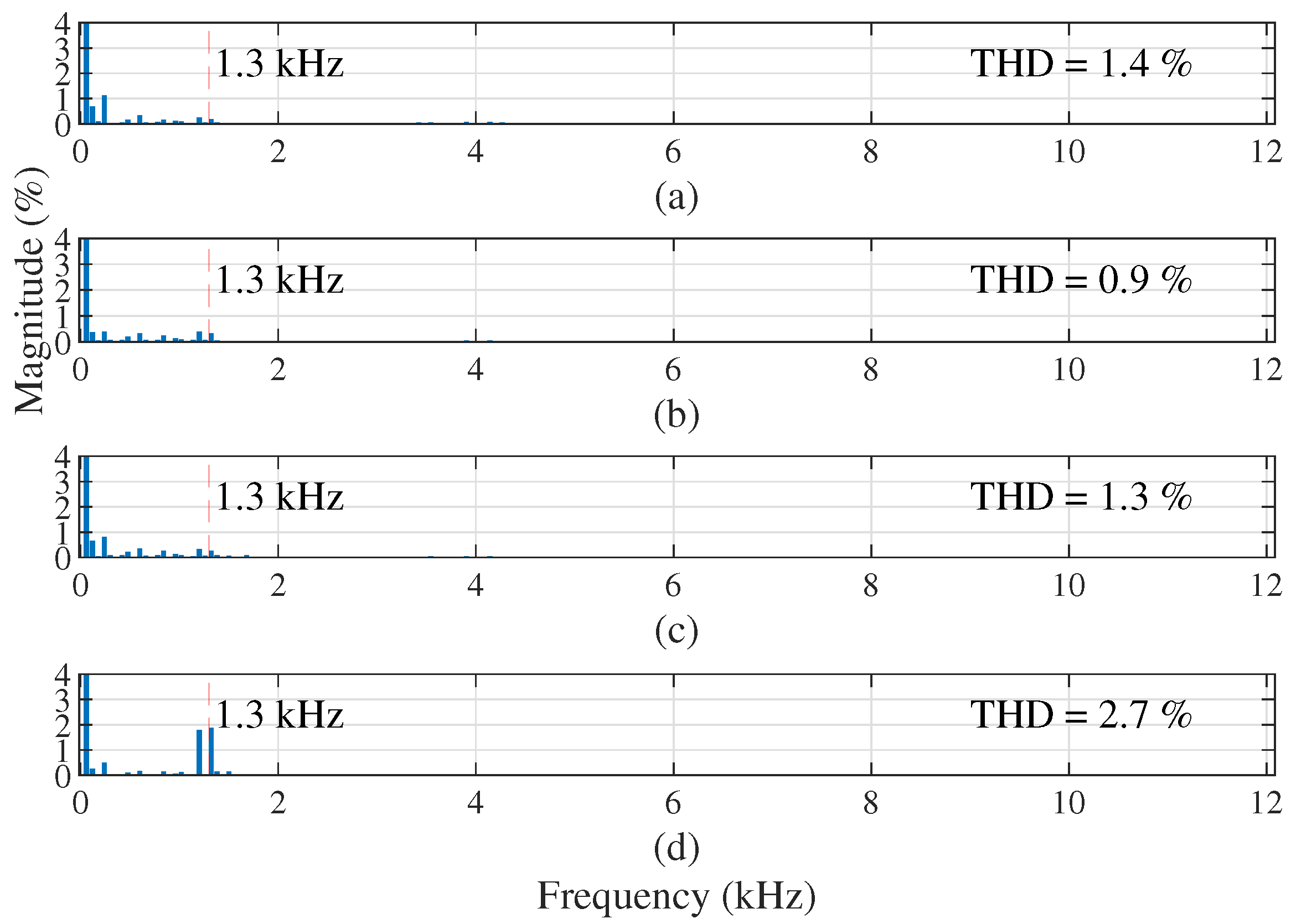
5. Results
6. Conclusions
Author Contributions
Funding
Conflicts of Interest
Abbreviations
| AD | Active damping |
| CCF | Capacitor current feedback |
| CVF | capacitor voltage feedback |
| IFOC | Indirect field oriented control |
| IM | Induction motor |
| MV | Medium voltage |
| NF | Notch filter |
| NPC | Neutral Point Clamped |
| PD | Passive damping |
| PWM | Pulse width modulation |
| VSD | Variable speed drives |
References
- Gates, G.; Shipp, D.; Vilcheck, W. Electrical distribution system analysis for off-shore oil production facilities. IEEE Trans. Ind. Appl. 2000, 36, 222–230. [Google Scholar] [CrossRef]
- Schaffner. Sine Wave Filter Solutions for Motor Drive Applications. 2020. Available online: https://docs.rs-online.com/1309/0900766b81523b4e.pdf (accessed on 28 July 2022).
- Guzinski, J. Closed loop control of AC drive with LC filter. In Proceedings of the 2008 13th International Power Electronics and Motion Control Conference, Poznan, Poland, 1–3 September 2008; pp. 994–1001. [Google Scholar] [CrossRef]
- Kan, G.; Huang, S.; Zou, X. Active damping of output LCL filter in PWM inverter-fed drive system with long motor cable. In Proceedings of the 2016 19th International Conference on Electrical Machines and Systems (ICEMS), Chiba, Japan, 13–16 November 2016; pp. 1–4. [Google Scholar]
- Rodriguez, J.; Pontt, J.; Silva, C.; Musalem, R.; Newman, P.; Vargas, R.; Fuentes, S. Resonances and overvoltages in a medium-voltage fan motor drive with long cables in an underground mine. IEEE Trans. Ind. Appl. 2006, 42, 856–863. [Google Scholar] [CrossRef]
- Eaton. Output Filters and Motor Lead Length Drive Applications. 2013. Available online: https://www.eaton.com/content/dam/eaton/products/industrialcontrols-drives-automation-sensors/variable-frequency-drives/powerxl-dh1-variable-frequency-drives/output-filters-and-motor-lead-length-ap040213en.pdf (accessed on 28 July 2022).
- Kouro, S.; Rodriguez, J.; Wu, B.; Bernet, S.; Perez, M. Powering the Future of Industry: High-Power Adjustable Speed Drive Topologies. IEEE Ind. Appl. Mag. 2012, 18, 26–39. [Google Scholar] [CrossRef]
- Salomaki, J.; Hinkkanen, M.; Luomi, J. Sensorless Control of Induction Motor Drives Equipped with Inverter Output Filter. IEEE Trans. Ind. Electron. 2006, 53, 1188–1197. [Google Scholar] [CrossRef]
- Mishra, P.; Maheshwari, R. Active damping control of induction motor drive with LC filter. In Proceedings of the 2016 IEEE International Conference on Power Electronics, Drives and Energy Systems (PEDES), Trivandrum, India, 14–17 December 2016; pp. 1–6. [Google Scholar] [CrossRef]
- Liserre, M.; Dell’Aquila, A.; Blaabjerg, F. Genetic algorithm-based design of the active damping for an LCL-filter three-phase active rectifier. IEEE Trans. Power Electron. 2004, 19, 76–86. [Google Scholar] [CrossRef]
- Hatua, K.; Jain, A.K.; Banerjee, D.; Ranganathan, V.T. Active Damping of Output LC Filter Resonance for Vector-Controlled VSI-Fed AC Motor Drives. IEEE Trans. Ind. Electron. 2012, 59, 334–342. [Google Scholar] [CrossRef]
- Parida, N.; Das, A. A Modular Multilevel Converter with Filter Capacitor for Long-Cable-Fed Drive Application. IEEE Trans. Ind. Appl. 2019, 55, 7833–7842. [Google Scholar] [CrossRef]
- Yuen, K.K.F.; Chung, H.S.H. A Low-Loss “RL-Plus-C” Filter for Overvoltage Suppression in Inverter-Fed Drive System with Long Motor Cable. IEEE Trans. Power Electron. 2015, 30, 2167–2181. [Google Scholar] [CrossRef]
- Sridharan, S.; Krein, P.T. A transfer function approach to active damping of an induction motor drive with LC filters. In Proceedings of the 2015 IEEE International Electric Machines Drives Conference (IEMDC), Coeur d’Alene, ID, USA, 10–13 May 2015; pp. 834–840. [Google Scholar] [CrossRef]
- Wiseman, J.; Wu, B. Active damping control of a high-power PWM current-source rectifier for line-current THD reduction. IEEE Trans. Ind. Electron. 2005, 52, 758–764. [Google Scholar] [CrossRef]
- Gomes, C.C.; Cupertino, A.F.; Pereira, H.A. Damping techniques for grid-connected voltage source converters based on LCL filter: An overview. Renew. Sustain. Energy Rev. 2018, 81, 116–135. [Google Scholar] [CrossRef]
- Gonçalves, D.; Farias, J.V.M.; Pereira, H.A.; Luiz, A.S.A.; Stopa, M.M.; Cupertino, A.F. Design of Damping Strategies for LC filter in medium voltage induction motor drives. In Proceedings of the 2021 Brazilian Power Electronics Conference (COBEP), João Pessoa, Brazil, 7–10 November 2021; pp. 1–7. [Google Scholar] [CrossRef]
- Twining, E.; Holmes, D. Grid current regulation of a three-phase voltage source inverter with an LCL input filter. IEEE Trans. Power Electron. 2003, 18, 888–895. [Google Scholar] [CrossRef] [Green Version]
- Peña-Alzola, R.; Liserre, M.; Blaabjerg, F.; Sebastián, R.; Dannehl, J.; Fuchs, F.W. Systematic Design of the Lead-Lag Network Method for Active Damping in LCL-Filter Based Three Phase Converters. IEEE Trans. Ind. Inform. 2014, 10, 43–52. [Google Scholar] [CrossRef] [Green Version]
- Dannehl, J.; Liserre, M.; Fuchs, F.W. Filter-Based Active Damping of Voltage Source Converters with LCL Filter. IEEE Trans. Ind. Electron. 2011, 58, 3623–3633. [Google Scholar] [CrossRef]
- Yao, Y.; Huang, Y.; Peng, F.; Dong, J.; Zhu, Z. Dynamic-Decoupled Active Damping Control Method for Improving Current Transient Behavior of LCL-Equipped High-Speed PMSMs. IEEE Trans. Power Electron. 2022, 37, 3259–3271. [Google Scholar] [CrossRef]
- Yang, M.; Lyu, Z.; Xu, D.; Long, J.; Shang, S.; Wang, P.; Xu, D. Resonance Suppression and EMI Reduction of GaN-Based Motor Drive with Sine Wave Filter. IEEE Trans. Ind. Appl. 2020, 56, 2741–2751. [Google Scholar] [CrossRef]
- Li, H.; Yin, Q.; Wang, Q.; Luo, H.; Hou, Y. A Novel DC-Link Voltage Feedback Active Damping Control Method for IPMSM Drives with Small DC-Link Capacitors. IEEE Trans. Ind. Electron. 2022, 69, 2426–2436. [Google Scholar] [CrossRef]
- Xue, C.; Zhou, D.; Li, Y. Finite-Control-Set Model Predictive Control for Three-Level NPC Inverter-Fed PMSM Drives with LC Filter. IEEE Trans. Ind. Electron. 2021, 68, 11980–11991. [Google Scholar] [CrossRef]
- Peña-Alzola, R.; Liserre, M.; Blaabjerg, F.; Sebastián, R.; Dannehl, J.; Fuchs, F.W. Analysis of the Passive Damping Losses in LCL-Filter-Based Grid Converters. IEEE Trans. Power Electron. 2013, 28, 2642–2646. [Google Scholar] [CrossRef] [Green Version]
- Novotny, D.W.; Lipo, T. Vector Control and Dynamics of AC Drives; Clarendon Press: New York, NY, USA, 1996. [Google Scholar]
- Ellis, G.; Lorenz, R. Comparison of motion control loops for industrial applications. In Proceedings of the Conference Record of the 1999 IEEE Industry Applications Conference. Thirty-Forth IAS Annual Meeting (Cat. No.99CH36370), Phoenix, AZ, USA, 3–7 October 1999; Volume 4, pp. 2599–2605. [Google Scholar] [CrossRef]
- Bae, B.H.; Sul, S.K. A compensation method for time delay of full digital synchronous frame current regulator of PWM AC drives. In Proceedings of the Conference Record of the 2001 IEEE Industry Applications Conference, 36th IAS Annual Meeting (Cat. No.01CH37248), Chicago, IL, USA, 30 September–4 October 2001; Volume 3, pp. 1708–1714. [Google Scholar] [CrossRef]
- Buso, S.; Mattavelli, P. Digital Control in Power Electronics; Morgan & Claypool Publishers: San Rafael, CA, USA, 2006. [Google Scholar]
- Harnefors, L.; Nee, H.P. Model-based current control of AC machines using the internal model control method. IEEE Trans. Ind. Appl. 1998, 34, 133–141. [Google Scholar] [CrossRef]
- Liserre, M.; Dell’Aquila, A.; Blaabjerg, F. Stability improvements of an LCL-filter based three-phase active rectifier. In Proceedings of the 2002 IEEE 33rd Annual IEEE Power Electronics Specialists Conference. Proceedings (Cat. No.02CH37289), Cairns, QLD, Australia, 23–27 June 2002; Volume 3, pp. 1195–1201. [Google Scholar] [CrossRef]
- Yao, W.; Yang, Y.; Zhang, X.; Blaabjerg, F.; Loh, P.C. Design and Analysis of Robust Active Damping for LCL Filters Using Digital Notch Filters. IEEE Trans. Power Electron. 2017, 32, 2360–2375. [Google Scholar] [CrossRef] [Green Version]
- Cathey, J.J.; Cavin, R.K.; Ayoub, A.K. Transient Load Model of an Induction Motor. IEEE Trans. Power Appar. Syst. 1973, PAS-92, 1399–1406. [Google Scholar] [CrossRef]
- de Paula, V.C.; de Paula, H. Employing DC Transmission in Long Distance AC Motor Drives: Analysis of the Copper Economy and Power Losses Reduction in Mining Facilities. IEEE Trans. Ind. Appl. 2018, 54, 841–847. [Google Scholar] [CrossRef]
- BITNER. Mining Cables. 2011. Available online: https://bitner.com.pl/data/t5txt_photos/08383171216_Mining_cable.pdf (accessed on 18 July 2022).


| Description | Parameters | Value |
|---|---|---|
| Rated Power | 500 hp | |
| Rated Voltage | 2.3 kV | |
| Rated Speed | 1773 rpm | |
| Rated Frequency | 60 Hz | |
| Poles | P | 4 |
| Stator Resistance | 0.262 | |
| Rotor Resistance | 0.187 | |
| Stator Self-inductance | 0.1465 H | |
| Rotor Self-inductance | 0.1465 H | |
| Magnetizing Inductance | 0.1433 H | |
| Moment of Inertia | J | 11.062 kg m |
| Friction Coefficient | D | 0.402 N ms |
| Switching Frequency | 4 kHz | |
| Sampling Time | 0.25 ms | |
| Reactance/Resistence ratio | 40 | |
| Filter Inductance | 1.88 mH | |
| Filter Capacitance | C | 9.80 F |
| Control Loop | Gains | |
|---|---|---|
| Proportional | Integral | |
| Direct Current | 10.3 | 329 /s |
| Quadrature Current | 9.85 | - |
| Speed | 347 N ms | - |
| Position | 2181 Nm | 137 Nm/s |
| Unit Resistance | Unit Inductance | Unit Capacitance |
|---|---|---|
| /km | mH/km | F/km |
| 1.15 | 0.372 | 0.11 |
| Strategy | Positives | Negatives |
|---|---|---|
| -No additional | -Additional | |
| PD | measurements | losses |
| -Closed-loop poles | ||
| unaffected | ||
| -No additional losses | -Require 3 extra | |
| CCF | -Barely affects | current sensor |
| the closed-loop poles | -More expensive | |
| -No additional losses | -Require 3 extra | |
| CVF | -Voltage measurements | voltage sensor |
| is less expensive than | -More expensive | |
| current measurements | ||
| -Less effective | ||
| NF | -No additional losses | damping |
| -No additional | -Sensitive to | |
| sensors | resonance frequency | |
| changes |
Publisher’s Note: MDPI stays neutral with regard to jurisdictional claims in published maps and institutional affiliations. |
© 2022 by the authors. Licensee MDPI, Basel, Switzerland. This article is an open access article distributed under the terms and conditions of the Creative Commons Attribution (CC BY) license (https://creativecommons.org/licenses/by/4.0/).
Share and Cite
Gonçalves, D.; Farias, J.V.M.; Pereira, H.A.; Luiz, A.-S.A.; Stopa, M.M.; Cupertino, A.F. Design of Damping Strategies for LC Filter Applied in Medium Voltage Variable Speed Drive. Energies 2022, 15, 5644. https://0-doi-org.brum.beds.ac.uk/10.3390/en15155644
Gonçalves D, Farias JVM, Pereira HA, Luiz A-SA, Stopa MM, Cupertino AF. Design of Damping Strategies for LC Filter Applied in Medium Voltage Variable Speed Drive. Energies. 2022; 15(15):5644. https://0-doi-org.brum.beds.ac.uk/10.3390/en15155644
Chicago/Turabian StyleGonçalves, Diuary, João Victor Matos Farias, Heverton Augusto Pereira, Alex-Sander Amável Luiz, Marcelo Martins Stopa, and Allan Fagner Cupertino. 2022. "Design of Damping Strategies for LC Filter Applied in Medium Voltage Variable Speed Drive" Energies 15, no. 15: 5644. https://0-doi-org.brum.beds.ac.uk/10.3390/en15155644