
Overview of Inertia Enhancement Methods in DC System
State Key Laboratory of Electrical Insulation and Power Equipment, Xi’an Jiaotong University, Xi’an 710049, China
*
Author to whom correspondence should be addressed.
Energies 2022, 15(18), 6704; https://0-doi-org.brum.beds.ac.uk/10.3390/en15186704
Submission received: 6 August 2022
/
Revised: 1 September 2022
/
Accepted: 8 September 2022
/
Published: 13 September 2022
(This article belongs to the Special Issue Modeling, Control and Design of Power Electronics Converters)
Abstract
:The modern power system is experiencing transformation from the rotational-generation-equipment-dominated system to a power-electronics-converter-dominated system, with the increasing penetration of renewable energy resources such as wind and photovoltaic. The power-electronics-based renewable generation, as well as energy storage system, can lead to the reduction of system inertia. As dc systems such as dc microgrids are attracting more attention, the low-inertia issues will challenge their stability. In this paper, a comprehensive review of inertia-enhancement methods in dc power systems is presented. The concept and significance of the inertia in dc systems is firstly introduced, and then the types of inertia-providing sources in dc systems are discussed. After that, the different virtual inertia control strategies applied in power electronics converters are classified and investigated. These virtual inertia control methods are proven to have a great ability to enhance the inertia of a dc system. The challenges and future research direction are discussed at the end of the article. In this paper, the previous research work on the inertia of dc power systems is summarized in detail, the inertia-enhancement methods of DC systems are comprehensively introduced, and the future research directions are prospected.
1. Introduction
The overexploitation and utilization of fossil energy has given rise to troublesome issues, such as energy shortage and environmental pollution [1,2,3,4]. The development of renewable energy sources (RESs) can be an environmentally friendly solution to alleviate the problems of the energy crisis and carbon emissions [5,6]. According to the Global Status Report of Renewable Energy in 2021 [7], in spite of the impact of the COVID-19 pandemic, more than 256 GW of RESs capacity was added globally during 2020, still surpassing the previous record by around 30%. Moreover, it was the only type of electricity generation that kept net growth.
Considering that the conventional power system is not suitable for large-scale RESs’ access, microgrids (MGs) were proposed and have been deeply studied [8,9]. Integrating the RESs, an energy storage system (ESS), and loads, MGs have merits in RESs accommodation and providing stable power supply for users. Depending on the type of bus voltage in MGs, the microgrids can be classified into ac MGs, dc MGs, and ac/dc hybrid MGs [10,11]. Research, as well as the literature, focuses on ac microgrids, since the utility grid relies on an ac system [12,13]. However, owing to the inherent dc nature of various RESs, ESS, and loads, such as photovoltaic panels, battery energy storage, LEDs, and electrical vehicles, dc MGs are more suitable for those dc characteristic components’ access. Compared to ac MGs, neither reactive power nor harmonics exists in dc MGs, so higher efficiency and power quality can be achieved [14,15,16]. Therefore, dc systems such as dc distribution networks and dc MGs have developed rapidly in recent years.
However, the rapid growth of RESs is raising new problems in regard to the new-type electrical system. On the one hand, the intermittent and fluctuation of sustainable energy power generation brings difficulty to the power system in real-time power balance. This problem is particularly prominent for MGs with distributed RESs as the main energy sources. The power mismatch between power generation and load demand will cause the frequency excursion and fluctuation in ac MGs [17], while in dc MGs, the unbalanced power manifests as the voltage deviation and the voltage fluctuation [10]. On the other hand, RESs are connected to the power grid through power electronics devices, which have no ability to provide mechanical inertial response as the rotational power generation equipment [18]. With the transformation from the traditional generator-based system to the power electronics converter-based system, the modern power system, especially distribution network or MG composed of distributed RESs connected by power electronic converters, is presenting the characteristic of low inertia and weak damping [19,20]. Low inertia and weak damping may cause system stability problems. Among them, the more serious problem of the ac system is the frequency stability, while the main problem of the dc system is the voltage stability.
The frequency stability is of great significance and has the priority to be concerned in an ac power grid [21,22]. Normally the system should be operating at the nominal frequency. When the power fluctuations occur on the RESs generation side or loading side, the grid frequency may deviate from its nominal value. Once the frequency deviation exceeds the allowable limits, it will induce the tripping of the frequency relays in the system, and then it may lead to serious grid fault, and even collapse in the worst case [20]. In order to keep the balance between power generation and load consumption, a multi-timescale coordinated frequency control strategy is proposed and implemented in the power system, which is illustrated in Figure 1. It can be seen from Figure 1 that inertia control plays an important role in hindering the sudden change of frequency within the first few seconds (1–10 s). The system inertia is usually provided by the rotational generator, such as a synchronous generator (SG), which can offset the imbalance power by absorbing or releasing the kinetic energy stored in the rotors [23]. There have been many research studies aiming at enhancing the inertia levels of power-electronics-based ac MGs, and virtual synchronous generator (VSG) control is the most potential and widely used method [24,25,26,27].
The penetration of a high proportion of RESs and power-electronics-based equipment also reduces the inertia of the dc system. In dc system, the frequent switching loads and intermittent RES generation (e.g., photovoltaic source and wind resource) can make the dc bus voltage fluctuate greatly and reduce the efficiency and stability of the system. Reference [28] analyzes the reasons for the voltage instability in the dc MG system and gives the method for voltage stability control. In Reference [29], the relationship between the damping and inertia of the dc system is studied. A unified concept is proposed by connecting the oscillation-related stability issues raised by weak damping with the sudden change in voltage that originates from low inertia. However, these works from the literature mainly focus on the study of the mechanistic reasons for the low inertia of the dc system; the research on the dc inertia enhancement methods has only begun to rise with the application and promotion of dc MGs in recent years. The dc bus voltage stability is the only concern in dc MGs, and the methods of emulating the inertia of the dc system are different from those in the ac system. Appropriate inertia control can mitigate the voltage deviation, as well as the voltage oscillation, and maintain the dc voltage stability [29,30,31].
At present, many scholars have summarized and prospected the research work on the low-inertia problem of power system. In Reference [20], current state-of-the-art of virtual inertia implementation techniques are summarized, and potential research directions and challenges about low-inertia issues are also explored. Reference [23] presents a comprehensive review of inertia-enhancement methods, including both proven technologies and emerging ones, and also discusses the impact of inertia on frequency control. However, these review articles are all focused on inertia-enhancement methods for ac systems, and the research work on dc inertia problems is rarely summarized. This paper presents an overview of the inertia-enhancement methods in the dc system. By summarizing the past research work on the inertia of the dc power system, this article generalizes the definition and physical meaning of the inertia in the dc power system and sorts out the inertia-supply sources. This paper also highlights the state-of-the-art inertia-control methods for power electronic converters, and future research directions are also prospected.
The remaining part of this paper is organized as follows: The concept of the inertia in dc system and the classification of inertia enhancement methods based on inertia-providing sources are introduced in Section 2. In addition, the necessity of inertia is discussed. Then various virtual inertia control algorithms and design processes are detailed in Section 3. The advantages and disadvantages of each method are also presented. Finally, the technical challenges and possible future research directions are discussed in Section 4. The last past is the conclusions in Section 5.
2. Concept and Classification of Inertia Enhancement in DC System
2.1. Concept of Inertia in DC System
In an ac system, the inertia is represented by the ability to impede the frequency abruptly, which is generally provided by SG in traditional system [20]. The power-balance equation of SG is expressed as follows:
where , , , , and are the mechanical power, the electromagnetic power, the damping coefficient, the angular frequency of SG, and the nominal frequency of the system, respectively; and is the moment of inertia.
As the frequency decreases, the SGs automatically slow down and release the kinetic energy stored in the rotors; therefore, the rate of change of frequency (RoCoF) is reduced, and the frequency nadir is improved. The kinetic energy of the rotors is expressed as follows [20]:
The existence of system inertia can provide SGs with sufficient time to adjust power output and re-establish the power balance. The time constant of inertia is described as follows:
where denotes the rated capacity of SG.
Correspondingly, inertia in dc systems such as dc MGs manifests the ability to mitigate the sudden change of the dc voltage, and the dc-link capacitors are the components which provide the inertia of dc MGs [32]. To illustrate the principle of how capacitors play roles in inertia response to the voltage abrupt, the relationship between voltage and current on both sides of the dc-link capacitor is shown in Figure 2, and it is described as follows:
where denotes the output current of the converter, denotes the current flows to the dc bus, denotes the capacitor current, C denotes the capacitor of the dc bus, and denotes the dc bus voltage.
Multiply both sides of the Equation (4) by , and the formula of power balance can be obtained:
where denotes the output power of the converter, denotes the power flows to the dc bus, and denotes the power charging of the capacitor. It can be known from (4) and (5) that the unbalanced power between and is compensated by the dc-link capacitor. When the dc bus voltage decreases, the capacitor releases its saved energy and provides active power support; therefore, the rate of change of voltage (RoCoV) is reduced, and the voltage nadir is improved, and vice versa. As the power balance in dc MGs is achieved, the dc-link capacitor stops charging or discharging, indicating that the inertia has no effect on the steady state.
Similarly, the energy stored in capacitors and the time constant of inertia in dc MGs can be described as follows:
where denotes the rated capacity of capacitors.
According to the previous analysis, the larger the dc-link capacitance, the larger the inertia time constant and the system inertia. However, the dc-link capacitance in dc MGs is usually limited and small, so the system inertia supplied by parallel capacitors is too insufficient to suppress the dc bus voltage abruptly, and so it consequently needs to be enhanced. Note that the topology of non-isolated bi-directional dc/dc converter shown in Figure 2 is just an example; the above analysis can also apply to other topologies, such as dual active bridge (DAB) dc/dc converters [33,34,35,36], LLC converters [37], CLLC converters [38], and so on.
2.2. Classification of Inertia-Providing Sources
To further enhance the system inertia, it is necessary to fully discuss the possible inertia-providing sources in the dc system. A typical topology of dc MG is depicted in Figure 3. It is usually composed of RESs (e.g., solar energy and wind energy), energy storage units, and loads [39,40]. These elements are connected to the dc bus through power electronic converters, which lack the capability of inertia support [41,42,43]. Therefore, the dc MG is a classical low-inertia system.
In a dc MG, the sources capable of providing the system inertia can be mainly divided into three types: support by wind turbines, support by energy storage units, and support by photovoltaic (PV) arrays. The classification is shown in Figure 4.
2.2.1. Inertia Support by Wind Turbines
Wind energy is one of the most promising sustainable energy resources, and wind turbines have the potential to emulate inertia by adjusting the rotating speed and releasing/absorbing the rotor’s kinetic energy, similar to SGs [44,45,46]. The scheme of permanent magnetic synchronous generator (PMSG)-based wind-generation system in dc MGs is depicted in Figure 5. It can be seen that the ac/dc converter connects the stator windings of the wind turbine with dc bus, and the wind turbine can achieve maximum wind-energy capture through the maximum power point tracking (MPPT) control of the converter. However, the isolation effect of the converter decouples the mechanical and electrical parts of the wind-generation system, so there is no direct coupling relationship between wind turbine’s rotating speed and dc bus voltage. The wind turbine thence cannot directly respond to the voltage change of the dc bus, and its large amounts of rotational kinetic energy may hardly contribute to support the system power deficit or surplus, resulting in low inertia in dc MGs.
Many research studies focus on how to take full advantage of the mechanical inertia potential of wind turbines in dc MGs [47,48,49,50,51,52]. Reference [47] establishes the relationship between the kinetic energy of wind turbine and the capacitor and then introduces the virtual capacitor into the dc MG with wind/energy storage, which improves the system inertia by releasing the kinetic energy on the rotor of the wind turbine. The system stability after introducing virtual inertia is also judged. The detailed virtual inertia control method is detailed in Section 3. In References [48,49], the connection between dc bus voltage fluctuation and the rotor speed change is built, so that the wind turbine can provide virtual inertial power from the kinetic energy stored in the rotor when the DC bus voltage fluctuates. To solve the contradiction between inertia support and maximum power point operation, the MPPT curve is designed to smoothly switched during the inertia-response period, but this method is too complicated. These methods essentially change the power output reference of wind turbines through controlling the converter, so the original operation point of the wind turbine is inevitably changed, maybe resulting in stability issues. The technical difficulties of utilizing wind power to provide system inertia are in the following aspects: fast and accurate response, smooth transition of power, electrical and mechanical system safety, and overspeed/underspeed shutdown. These challenges require further study.
2.2.2. Inertia Support by Energy Storage Units
Energy storage units (ESUs) interfaced with power electronic devices have become an effective means of solving the power fluctuation of RES generation due to their rapid regulation capabilities [53,54]. Moreover, ESUs can provide inertia support by fast charging or discharging. The dc-link capacitor is a typical energy storage element, and its mechanism that provides inertia was discussed above. Currently, ESUs applied in dc MGs include battery energy storage, supercapacitor, flywheel, and so on, and among them, battery energy storage (BES) and supercapacitor (SC) have mature techniques and widespread application prospects.
References [32,55] introduced the RoCoV into the droop coefficient and proposed an improved droop control method. This method is applied in the accumulator battery-connected converter, and then the inertia enhancement is implemented. Although battery has the advantages of high-energy density, its charging and discharging efficiency is relatively low, which is not suitable for frequent charging and discharging to stabilize the power fluctuation of the system. In addition, when using the inertial control method, the slow dynamic response of battery has also become the bottleneck for the function of inertia control. Because of its high-power density, long cycle life, and high charge and discharge efficiency, the supercapacitor is suitable for suppressing high-frequency power fluctuation [56]. However, the costs of supercapacitors are relatively high. Moreover, when the dc system is in the steady-state operation, these supercapacitors are idle, which causes resource waste. Therefore, the hybrid energy storage system (HESS) composed of a battery and supercapacitor is proposed, as it combines the advantages of both the battery and supercapacitor and has been adopted and utilized for inertia support.
The common ways to access HESS in dc MGs includes parallel connection and three-port converter connection [55,57,58]. In Reference [55], a HESS-based inertia control method is given, and it adopts the parallel connection, as illustrated in Figure 6a. In terms of control strategy, except for the power-distribution scheme, the control method of the supercapacitor converter is the same as that of the battery energy storage converter. According to the difference of the charging/discharging characteristics between batteries and supercapacitors, the reference current absorbed or released by HESS is divided into two parts through a low-pass filter (LPF): low-frequency part and high-frequency part. Supercapacitors are intended to mitigate the high-frequency power fluctuation induced by RESs or load mutation and provide inertial support for the dc bus. As a long-term power-balance device, batteries absorb or release low-frequency power to keep the steady-state operation in dc MGs. The way of parallel connection for HESS has a simple structure and ease to implement, but it needs more power electronics converters, resulting in inevitable power loss.
In order to further improve the power density and conversion efficiency of the HESS converter, some scholars propose to use a three-port converter as a hybrid energy storage converter [59,60]. Moreover, the three-port converter is also beneficial to the modular design of the HESS. However, the control strategies for batteries and supercapacitors have become more complex and need further research.
2.2.3. Inertia Support by PV Arrays
In general, PV arrays are integrated into the dc MGs through a boost converter, which MPPT control is applied to in order to guarantee the maximum PV power output. Moreover, PV arrays belong to non-rotating stationary element and have no inherent inertia. Therefore, PV arrays seldom take the responsibility of system inertia support. It is feasible for PV to provide inertia by adjusting its operation point apart from maximum power point [61,62], but this method could lead to the reduction of PV generation efficiency [63,64,65]. Reference [66] proposed a control strategy of PV system based on the virtual dc generator to eliminate the effect of load and light-intensity change on PV system. The proposed topology of PV system is illustrated in Figure 7, where and denote the output voltage and current of PV arrays, respectively; is the output voltage of the first stage boost converter; and and are the output voltage and current of the second stage boost converter, respectively. As shown in Figure 7, a two-stage boost converter interconnects the PV arrays to the dc bus. The first-stage boost converter is intended to track the maximum power point of PV, while the second-stage boost converter is intended to regulate the dc bus voltage. By the way of emulating the dc machine, the PV generation system has the similar output characteristic, and the PV output and dc bus voltage change more gently. The control method of virtual dc machine is introduced in Section 3. However, it needs to be emphasized that the way of providing inertia by adjusting the PV output power may cause the PV output to deviate from the maximum power point, resulting in energy waste.
In addition to the abovementioned inertia-providing sources, the dc MGs working at the grid-connected mode can also obtain inertia support from the utility grid. Considering that frequent charging/discharging may damage the life cycle of a battery, a power-management strategy based on virtual inertia is presented [67]. In Reference [67], the ac-grid-connected inverter is designed to maintain the dc bus voltage, and a utility grid, instead of a battery, provides the inertia support. This method can reduce the burden of the battery and prolong its life cycle. Moreover, some motor loads can also provide rotational inertia, but related research is limited. We discuss it in Section 4.
As noticed, all the inertia enhancement methods rely on the control strategies of the connected power electronics converters (e.g., dc/dc converter and dc/ac converter); hence, the principle and classification of inertia control is discussed next.
2.3. Classification: According to Inertia Control Method
The inertia-control method can be mainly divided into two types: direct inertia control (DIC) and virtual inertia control (VIC). The detailed classification is shown in Figure 8.
DIC refers to providing inertia by controlling traditional rotating-power-generation equipment such as SGs [47]. However, the modern power system is experiencing the transition from a rotational-generator-dominated system to a power-electronics-converter-dominated system, and SGs is gradually replaced by RESs. Thus, DIC is not the main research focus in this article.
VIC refers to providing virtual inertia by controlling power electronics converters connected to RESs or ESS, which belong to non-rotating stationary equipment and have no ability to directly provide inertia. VIC is the main focus of this article.
To further explain the meaning of virtual inertia control, the dc-side equivalent circuit of the converter in dc MGs is depicted in Figure 9. Similar to the previous one in Figure 2, denotes the output power of the converter, denotes the power flowing to the dc bus, denotes the power charging of the capacitor, and C denotes the dc-link capacitance. Different from the voltage and current double-loop control used in the converter in Figure 2, the converter in Figure 9 adopts virtual inertia control, so denotes the extra output power by the converter using virtual inertia control.
The formula of power balance on both sides of the dc-link capacitor based on Equation (5) can be obtained as follows:
where is the value of virtual capacitance. It can be known from (8) that extra power output by controlling the converter is equivalent to virtualizing a larger capacitance in the dc-link, and the time constant of inertia in dc MGs which characterizes the inertia of the system is correspondingly enhanced, just as (9) expresses:
To sum up, the virtual inertia control essentially allows converters to generate extra power output and virtualizes a larger dc-link capacitance, thus enhancing the system inertia. The detailed classification and introduction of each type of VIC is give in the next section.
3. Virtual Inertia Control Methods
In this section, the various VIC methods are introduced, and the strengths and weaknesses of these methods are also discussed and compared.
3.1. Additional Inertia Control
The additional inertia control (AIC) mainly refers to improving the traditional converter control method to output additional virtual power. More specifically, the AIC enables the converter to deliver additional power by coupling the virtual capacitor into the conventional converter control loop [32,48,49,55,68,69]. Therefore, the converter has the ability to provide inertia, while still retaining the original output characteristics.
Currently, the control architecture in dc distribution network (DN) or MGs mainly can be divided into two types: the centralized control structure and the decentralized one [41,42,43]. For the centralized control structure, all the RESs and ESS interface converters receive the unified dispatch from the central controller through communications. In Reference [70], a dc microgrid for data centers, using the centralized control framework, is proposed, and the central control system coordinates the operation of converter used in the dc microgrid and ensures the stable operation of the system. However, as the core device for the centralized control structure, the central controller is vulnerable to physical attacks or cyber-attacks, leading to the communication breakdown of the entire dc system.
For the above considerations, the decentralized control is presented in which the converters in a dc system make actions via local voltage or current information. The droop control is the typical decentralized control scheme [42]. In this scheme, the dc bus voltage deviation is used to automatically achieve power sharing among converters. The droop control equation in dc network can be expressed as follows:
where denotes the output voltage of the ith converter (i = 1, 2, 3, …), denotes the reference dc bus voltage, refers to the droop coefficient of the ith converter, and denotes the output current of the ith converter.
However, the droop control in dc systems just adjusts the deviation of the dc bus voltage from the primary regulation point of view and is not sensitive to the rate of change of voltage (RoCoV) and does not provide inertial support for the dc system. In order to enhance the system inertia, Reference [32] introduces the RoCoV into the droop control equation, and an improved droop control equation can be obtained as follows:
where indicates the function of RoCoV, and it is expressed as follows:
The reason for introducing RoCoV into the droop coefficient is that rapid power disturbances in dc systems manifest themselves as a large dc-bus-voltage change rate. It can be seen from (11) and (12) that the improved droop coefficient is negatively correlated with RoCoV. When the dc bus voltage remains constant, the RoCoV is equal to zero, and when the DC bus voltage fluctuates due to source-load fluctuations, the RoCoV () becomes large, and the droop coefficient becomes smaller; therefore, the interface converter will output a higher current to suppress the voltage fluctuation. Consequently, the interface converter adopting the improved droop-control strategy has the inertia-support capabilities.
Figure 10 presents the proposed improved droop-control architecture. It can be found that the battery energy storage is the inertia source, and its interface converter adopts the AIC. In the control architecture, the rate of change of the dc bus voltage is obtained through the high-pass filter (HPF) and used to calculate the droop coefficient; then the reference of the battery output current can be calculated by using the improved droop control. Finally, after the PI controller of inner current loop and PWM part, the switching-gate signals are generated and sent to the DC/DC converter.
Practically, the function of RoCoV is not linear as (11), because the inertia power is limited by the battery’s energy-storage capacity, and correspondingly, the droop coefficient also has the limitations. In Reference [32], the actual droop coefficient is designed to achieve the following:
where and are the limits of the droop coefficient. By designing the droop coefficient as an inverse tangent function about RoCoV, it prevents the droop coefficient from crossing the limit and ensures the stability of the system; at the same time, it makes full and reasonable use of the inertia margin of the converter, i.e., the variation margin of the droop coefficient, so that the battery can provide a large inertia for the system whether the load fluctuation is large or small. The advantage of this architecture is that the control principle is simple and inertia support can be provided quickly, but the disadvantage is that the voltage differential term is introduced, resulting in a high-frequency disturbance to the control system.
In addition to designing the droop factor as the reciprocal of the inverse tangent function, Reference [55] gives another form. It is designed as a power function:
where refers to the initial droop coefficient, and are the constants controlling the strength of inertia, and is the threshold for deciding whether to activate AIC. The meaning of Equation (15) is that, when the dc-bus voltage-change rate exceeds the set threshold, the droop coefficient of the converter’s droop control will be correspondingly reduced according to Equation (15), so that the converter can output more power to provide inertia support. It can be seen that values of parameters and in Equation (15) can affect the system inertia. The simulation results of the droop coefficients for different values of and show that the larger value of and smaller value of can enhance the inertia support capacity of the converter. Similarly, the range of values for and is determined according to the converter’s capacity and system’s stability margins.
Figure 11 presents the proposed control architecture in Reference [55]. The control scheme is similar to that of Reference [32], but the difference is that a model predictive controller is used to substitute the PI controller of inner current loop. It can effectively avoid the hysteresis of traditional PI-based internal loop current regulation and is suitable for applications requiring fast control, such as virtual inertia control. However, this method still needs to introduce the voltage change rate, so there is still the problem of high-frequency disturbance.
Moreover, a hybrid energy storage system (HESS) is used. The HESS is composed of battery energy storage (BES) and supercapacitor (SC). In terms of control strategy, except for the power-distribution scheme, the SC interface converter is controlled in the same way as the BES interface converter. The control block diagram is also depicted in Figure 11. The filtered high-frequency current reference is sent to the model predictive control (MPC)-based inner loop of SC interface converter, while the low-frequency current reference is sent to the MPC-based inner loop of BES interface converter.
Although the above methods of changing the droop coefficient improve the stability of the dc bus voltage, they still have drawbacks, such as complex control algorithms, output power that tends to exceed limits, transient response times that are too long, etc. In addition to changing the droop coefficient, virtual inertial control can also be achieved by adjusting the droop curve intercept [68]. The expression for the adjustment of the longitudinal intercept of the droop curve consists of a nested power function and inverse tangent function. The proposed method has a simpler control structure and reduces transient response time, but it does not comprehensively consider the operational boundaries of constraints such as stability, dynamic performance, and feasibility.
Instead of adjusting the droop curve to enhance the inertia, Reference [69] proposes a new control scheme to output extra power. The voltage fluctuation signal is introduced into the control loop of the BES interface converter, and the current reference value is compensated and changed by additional flexible virtual inertia control, so that the output power of the BES changes rapidly, thereby giving the power grid a certain inertia support. In Reference [48], a similar approach is applied to the grid-connected inverter in dc MGs, considering that the utility grid, as a large power source, can quickly provide sufficient inertial power. Reference [49] connects the maximum power-tracking coefficient of wind turbines and the virtual capacitance and adds the AIC part in to the MPPT control of wind turbines’ interface converter.
The AIC essentially couples the virtual capacitor into the original control loop of converters, changing the current reference value of the inner current loop. In general, these AIC methods have simple principles and are easy to implement. However, these methods all inevitably depend on the differential term of the dc voltage, thereby introducing additional high-frequency disturbances and coupling terms to the control loop, weakening the ability to release virtual inertia, and making the overall control structure complex and lacking in generality.
3.2. Analogous Virtual Synchronous Generator Control
In the ac grids, the virtual synchronous generator (VSG) control has been widely studied and applied. The VSG technology changes the inverter control strategy by introducing virtual inertia and damping into the control system, so that the output characteristics of the inverter are similar to those of the synchronous generator; thereby, the system inertia can be enhanced. Zhong et al. [26] first proposed the concept of synchronverters; the mechanical and electromagnetic properties of the synchronous machine are emulated in the well-established converter control algorithm. Furthermore, Zhong et al. [71] improved the control strategy and developed a self-synchronized synchronverter without a dedicated synchronization unit, such as a phase-locked loop (PLL). References [72,73] compare and analyze the dynamic characteristics of both the traditional droop control and VSG control, and Reference [72] proposes a generalized droop control for the grid-supporting inverter, which combines the advantages of both and can adapt to different requirements.
At present, the VSG technology in the ac system has been widely and deeply studied, and many scholars have begun to apply it to the dc system. The design of the VSG topology used in dc grids mimics the one in the ac system, whose swing equation [73] is expressed as follows:
where represents the active power reference of the inverter, represents the output power of the inverter, describes the damping effect of the VSG, is the damping factor, is the reference angular frequency generated by VSG, is the nominal angular frequency of the ac grids, and is the moment of inertia.
As discussed in Section 2.1, the inertia in the dc system manifests the ability to mitigate the sudden change of the dc voltage, and there are many variables that correspond to each other between both the VSG topology in the ac system and dc system. The similarities [74,75] are listed in Table 1.
According to Table 1, Reference [74] substituted the dc bus voltage for angular frequency in ac grids and proposed an analogous virtual synchronous generator (AVSG) control for a bi-directional grid-connected inverter (BGI) in the dc MG. The dc virtual inertia control equation is expressed as follows:
where represents the output current reference of the inverter; represents the actual output current of the inverter; describes the damping effect of the AVSG; is the damping factor; is the reference dc bus voltage generated by AVSG; is the nominal dc bus voltage; and is the virtual capacitance, analogizing with in (16).
Figure 12 presents the proposed AVSG control architecture in Reference [75] that consists of the AVSG control, the voltage and current dual-loop control, and the current feed-forward control. The AVSG control part mimics the dynamic characteristic of the synchronous generator and analogizes the VSG in the ac system. The output of this part is the error between dc bus voltage and its reference value, . The voltage and current dual loop receive the error signal between the dc-voltage reference value and actual value and output the duty cycle. The current outer loop is designed with a PI controller to track the dc-bus voltage reference, and the current inner loop is designed with decoupling of grid-connected current components in the d-axis and q-axis. Moreover, is the grid-connected current reference in the d-axis, which is set to zero because the BGI only transmits active current; is the grid-connected current reference in q-axis; and and are the grid-connected current and voltage in the d-q coordinate system, respectively.
In References [74,75], the small signal model of the proposed AVSG control is established, and the transfer function of output voltage to output current, as well as the step response, can be obtained. However, it was found that the dc bus voltage at the initial stage of the step response will experience an impulsive process of change after the sudden change of system power demand. An output current feed-forward control part is developed to compensate for the impulse component of the step response; thereby, the dynamic characteristics of the control system are improved.
However, there are limitations in the research work in References [74,75]. The proposed VIC for the BGI can be used only when dc MG is working in the grid-connected mode. When the dc MG operates in off-grid mode, the BGI will not be able to provide inertial support. In this case, it is difficult to ensure the safety and stability of the dc MG. In order to enhance the inertia of the dc MGs in both the grid-connected and off-grid mode, References [76,77] propose a similar AVSG control, which is used in the bi-directional dc/dc converter for the BES. The energy storage could provide inertia support regardless of the operating conditions of the dc MGs. The control block diagram has the same AVSG and current feed-forward parts as that in Reference [74], while in the voltage/current dual-loop control part, the inner current loop uses a PI controller.
By analogy with the VSG method used in ac system, the above AVSG methods applied to dc system exhibit good suppression of voltage surges. Zhu et al. [78] compares the AVSG control in Reference [76] with the AIC method in Reference [69]. The results show that, compared to the AIC method that introduces a voltage differential link, the AVSG control has better dynamic characteristics, and its stability is less affected by changes in control parameters. The AVSG control has good robustness.
Moreover, the influence of different types of VIC on dc MGs is also analyzed. The equivalent impedance model of the dc MGs is established, and the influence of changes in parameters such as virtual inertia coefficient (), dc bus capacitance, and load power on the system stability is studied according to the Middlebrook criterion. The conclusion is that, although the VIC method, similar to AVSG, can enhance the system inertia and improve the voltage quality, a large will reduce the system’s stability margin. The stability analysis provides a basis for the selection of controller and system parameters.
Aiming at further improving the inertial response capability of the system, a flexible virtual inertia control method is presented by Reference [79]. Based on the AVSG control structure, the virtual capacitance can be flexibly adjusted and expressed as follows:
where is the virtual inertia coefficient when the system is in steady state, is the set critical value of the dc bus voltage change rate, and and are the relevant parameters to adjust the virtual inertia coefficient. Theoretically, the larger the virtual inertia coefficient, the stronger the system inertia, so once the voltage mutation is detected and the dc bus voltage change rate becomes larger than , the virtual inertia coefficient will be changed to a larger value; thus, the proposed AVSG control is more flexible.
The problem with this approach is that the introduction of the voltage differential term will bring the interference of high-frequency noise to the control system. In addition, an excessive virtual inertia coefficient is known to affect the system stability; thus, the setting of and is particularly important, adding difficulty to the design of the control system. Although the above AVSG control methods can mitigate the voltage mutation, the speed of the voltage recovery stage is also slowed down. Therefore, Reference [80] improves the approach for the above problems and proposes an adaptative AVSG method. In Reference [80], is designed as a function in relation to the change rate of dc bus voltage and the voltage deviation. The design principle of can be illustrated in Figure 13.
In Figure 13, the sgn (x) is a symbolic function, the output 1 means the input is greater than zero, and the output 0 means the input is less than zero. The symbolic function can reduce the amount of computation and also avoid system noise brought by the differential term. Based on Figure 13, the expression of is as follows:
where is the set critical value of the dc bus voltage deviation, and is the relevant parameters to adjust . According to (18), when the sudden voltage change occurs, the voltage-change rate and the deviation have the same mathematics symbol, so is changed from its initial value of to a large value, meaning that system inertia is enhanced; when the dc bus voltage begins to recover, the voltage-change rate and the deviation have the opposite mathematics symbol, so is changed to its initial value of , meaning that system inertia is weakened, and the voltage recovers faster.
In recent research, some scholars combine the intelligent control, the intelligent optimization algorithm, with AVSG control to improve its performance. In Reference [81], a new adaptative virtual inertia control method is proposed that uses a fuzzy logic control (FLC) algorithm to flexibly adjust . Compared to the method in References [74,76], the state of charge (SOC) of the battery energy storage is also considered in the FLC algorithm to ensure the safety of BES. The feasibility is verified by simulation. References [82,83] propose an MPC-controlled AVSG approach. By comprehensively considering the allowed range rate of the dc-link voltage as the constraint and considering the output of VIC and voltage deviations as the optimization objectives, a prediction model is established. The predictive model can predict the optimal compensation current to change the input current reference of the AVSG controller; therefore, the system inertia is greatly enhanced. Meanwhile, some research has begun to focus on the design and simplification of the AVSG control models. More in-depth research for AVSG control is still needed.
3.3. Virtual DC Machine Control
Virtual dc machine (VDCM) control is a relatively emerging virtual inertial control method which mimics the characteristics of the dc machines to strengthen the dc system’s inertia. References [84,85,86] propose the VDCM concept, which is used in the bidirectional buck/boost converter. Reference [66] proposes the VDMC approach and applies it to boost the converter on the PV side. References [87,88] use VSG control and VDMC control on the ac and ac sides of the energy router, respectively, and a similar idea also appears in Reference [89], where the control method is applied to the cascaded power electronic converters. It is proved that VDCM can simulate the inertia and damping of the traditional ac power grid in the dc system. However, there are few works from the literature that involve a detailed analysis of the working principle and mechanism of VDCM, and none of the abovementioned works analyze the dynamic response of VDMC and the influence of parameter design on system stability.
An analogy is made to the key parameters of dc machine and VDCM in References [90,91,92]. Accordingly, the dc machine model is shown in Figure 14a.
From the equivalent circuit of the dc machine in Figure 14a, the equivalent equation in the electromagnetic part is calculated as follows:
where is the induced electric potential of the dc machine; and are the output voltage and output current of the armature winding, respectively; and are the armature resistance and armature inductance, respectively; and are the torque coefficient and magnetic flux, respectively; and is the rotor speed.
As the typical dc/dc converter topology, the non-isolated bi-directional dc/dc converter is shown in Figure 14b, and the equivalent circuit equation ca be expressed as follows:
where is the voltage on the output capacitor of the dc/dc converter; and are the dc bus voltage and the output current of the converter, respectively; and and are the line resistance and line inductance, respectively.
It can be known from (20) and (21) that the output circuit of the dc/dc converter can be completely equivalent to the armature of the dc machine. Specifically, the line impedance in the output ports of the converter corresponds to the armature winding of the dc machine, and the output voltage of the converter corresponds to the induced electric potential of the dc machine, so as to realize the complete equivalent process of the output circuit of the dc/dc converter and the electromagnetic part of the dc machine. Note that the topology of the non-isolated bi-directional dc/dc converter is selected to be analogous to the dc machine. The equivalent model of the output ports is not affected by changes in the internal topology of the converter. Therefore, the equivalent model can be also suitable for other converter topologies, such as the dual active bridge (DAB) dc/dc converter, LLC converter, CLLC converter, and so on.
Moreover, considering that the converter does not have inertial support capability, the mechanical motion equation of the dc machine should also be added to the control system. The power-balance equation for the dc machine’s mechanical part [90] is as follows:
where represents the mechanical power; is the electromagnetic power of the dc machine, which can be expressed by the product of angular velocity, , and torque, ; describes the damping effect of the dc machine, in which is the damping coefficient and and are the nominal rotor speed and the nominal output voltage of the dc machine, respectively; is the inertia power; and is the moment of inertia.
By combining the previous analogy, the VDCM control equation can be obtained as follows:
where , , , and represent the input power of the converter, the output electromagnetic power of the converter, the virtual damping power, and virtual inertia power of the converter, respectively; and denotes the virtual induced electric potential in VDCM control, which is also the output voltage in Figure 14a, emulating in the dc machine. Moreover, is the nominal dc voltage, is the virtual angular frequency, is the virtual moment of inertia, and is an adjustable parameter to mimic the armature winding resistance of the dc machine. The relationship between the mechanical motion equation in (23) and the output equivalent circuit in (21) manifests in (24). The detailed analogy between dc machine and VDCM control is listed in Table 2.
Combine (22) and (23) and Table 2, and the virtual capacitance can be calculated by using the following equation:
The control block diagram of VDCM is shown in Figure 15. The control structure proposed in Reference [90] can be mainly divided into three parts: the voltage outer loop, the VDCM control loop, and the current inner loop. In the voltage loop, a PI controller, , is utilized to track the reference dc voltage so that the steady-state voltage error can be eliminated. The purpose of the PI controller in current loop is the same and to track the input current of the converter. The VDCM controller consists of the mechanical part and the electromagnetic part. By emulating the dynamic characteristics of dc machine, the dc/dc converter with VDCM control can improve the dynamic stability of dc system voltages.
In Reference [90], the small signal model of the VDCM control is established, and its dynamic characteristic is also analyzed. The original small signal model is a fifth-order system, so it is hard to select the parameters such as and . To facilitate the analysis of the established model, a second-order simplified model is introduced by using the dominant poles. The second-order improved system can simplify the parameters’ design process, and the parameters in VDCM control are also optimized.
The proposed VDCM can mimic the dynamic characteristics of the dc machine well, and the response speed is fast. However, the adopted VDCM control model in Reference [90] is not perfect, and its dynamic response should be improved. Reference [93] compares a non-isolated bidirectional dc/c converter to a dc machine, and a new VDCM control block diagram is designed. Since the topology of the dc/dc converter is specifically considered in the modeling process, the small signal model is further simplified into a first-order system, and the improved VDCM control has more superior voltage dynamic performance and inertial support capability. Additionally, the problem of low sensitivity of the designed control system parameters has also been solved. The limitation of this method is that it relies on the internal topology of the converter, so it is not universal.
In addition, some scholars combine VDCM control with other traditional control methods, such as droop control. A VDCM control strategy based on the P-U droop characteristics is proposed in Reference [91]. The proposed method makes an analogy to the typical P-U droop control equation in the dc system and the mechanical inertia characteristics of the dc machine, by which the P-U droop control loop with VDCM is designed. Reference [92] adds the SOC of the distributed ESS to the armature resistance and proposes an improved VDCM control strategy, in which the dynamic power sharing, as well as the SOC balance, can be achieved. Reference [94] proposes a similar control method for SOC balance, which is also adapted to the dc MGs with multiple ESSs of different capacities. According to the current research, VDCM control has great potential to provide inertia support for dc system, but the current VDMC has not yet entered the stage of promotion and use, and its control structure needs to be further improved.
3.4. Comprehensive Comparison
In this section, the virtual inertia control methods for power electronics converters are classified and detailed. The respective advantages and disadvantages of these different types of control methods are summarized in Table 3. It can be seen that each type of virtual inertia control has its strengths and weakness. The AIC control is easy to implement, but the introduced high-frequency disturbance may lead to stability issues. At present, AVSG is more mature in terms of technical implementation, so it has the most potential in large-scale application. In theory, VDCM has better characteristics and is more suitable for a dc system, but it needs to be further simplified in terms of its modeling and control-system design. Therefore, a reasonable virtual inertial control method should be selected according to the actual needs.
4. Challenges and Future Research Direction
4.1. Improved Modeling of Virtual Inertia Control Methods
The current research on converter control methods for virtual inertia enhancement mainly focus on the design of the proposed control algorithms and specific implementation. However, these few works from the literature focus on the accurate system modeling analysis after applying these methods. In fact, refined modeling plays an important role in the transient process issues of the system. In addition to the value-range setting of the control system parameters [74], a refined modeling of the control system can be used to reveal the energy change of the system during the transient process. In Reference [95], a systematical modeling method is proposed to calculate the grid frequency support effect and the transient energy demand of VSG. Based on the modeling and calculation algorithm, a VSG parameter optimization method is presented to minimize the transient energy demand of VSG, while meeting the frequency support requirements of the grid. This research idea can also be extended to the VIC control of dc MGs Moreover, the improvement of the dynamic characteristics of the control strategy also depends on the small-signal modeling analysis of the algorithm and the system.
Therefore, more accurate modeling and transient process analysis of VIC methods will be one of the future research hotspots.
4.2. Influence of VIC on Multi-Machine Operation and System Stability
With the rise of RES penetration in the power system, the scale and number of RES units, as well as the ESS units, are also increasing, and this brings challenges to the multi-machine coordinated control and stable operation of the distribution network and microgrid. At present, the research on the system inertia enhancement method in the literature mostly takes a single converter as the control object to study its control strategy. However, the inertia of the current dc system is very low, and only relying on the virtual inertial control of a single inverter cannot provide sufficient inertial support for the dc system. Therefore, in the actual dc distribution network or dc MG scenarios, multiple converters are often involved in inertial support.
The advantage of using VIC for multi-machine control is that the characteristics of different types of inertial sources can be fully utilized to realize the complementarity of inertial supports. However, its shortcomings are also obvious: multi-machine operation greatly increases the complexity of system modeling and control system. The common issues caused by multi-parallel operation include the power-sharing and circulating-current problems. References [96,97,98,99] propose an adaptive virtual impedance-based VSG control approach to achieve the reactive proportional power sharing among multiple converters. However, most research on power sharing and circulating suppression focuses on ac systems, and such issues are rarely mentioned in articles on the virtual inertia control of dc systems. Moreover, the VIC for multi-parallel operation also adds difficulty to system-stability analyses [100,101]. In future research, it is necessary to further explore the detailed interaction mechanism of different types and quantities of inertia sources, including RES and ESS units; optimize the multi-machine cooperative control strategy; and ensure the stable operation of the system.
4.3. Consideration about Influence of Load Side on System Inertia
Whether it is an ac system or a dc system, the previous research on system inertia enhancement methods has revolved around the source side, while ignoring the possible inertia in the load side. Actually, the dc machine is one of the dc loads, which could provide inertia support by mechanical energy on its rotor. The electric-vehicle-charging station likewise has the similar inertia support capability [102]. As the type and quantity of loads with inertia characteristics increase, it is necessary to deeply analyze the internal relationship between different types of loads and the inertia, so as to design suitable control strategies according to types of loads and improve the stability of the system.
5. Conclusions
This paper presented a comprehensive review of the inertia enhancement method on dc system under high-RES penetration. First, this paper introduced the definition and function of inertia in the dc system, and then the different types of inertia sources, including wind turbines, photovoltaic arrays, and energy storage were introduced. The principle by which these inertia sources provide inertia and the scenarios in which they are used were also analyzed. Since these inertial sources have to provide inertia by controlling the interface converter, the virtual inertial control methods were classified and discussed in detail. Among these control strategies, the AIC methods have simple principles and are easy to implement, but they are susceptible to high-frequency noise. The AVSG control mimics the dynamic characteristic of the synchronous generator and has a good application prospect. The VDCM control method is an emerging technique, and it has great potential in inertia support. In the future, more research needs to be performed on improved schemes, refined modeling, multi-machine operation, and various load-side inertia controls. This review summarizes the research results of the inertia problem in the dc system and looks forward to the future research directions. It is expected to provide useful help and contribution to the development of the inertia emulating and enhancement technology in the dc power system.
Author Contributions
Conceptualization, F.W. and L.S.; methodology, F.W. and L.S.; investigation, L.S. and Z.W.; writing—original draft preparation, L.S.; writing—review and editing, F.W. and L.S.; visualization, L.S.; supervision, F.Z. All authors have read and agreed to the published version of the manuscript.
Funding
This research was funded by [Project Research on Key Technologies of High Gain, High Density, Modular PV System in MVDC Distribution Network supported by National Natural Science Foundation of China] grant number [52077173].
Conflicts of Interest
The authors declare no conflict of interest.
References
- Su, J.; Li, K.; Li, Y.; Xing, C.; Yu, J. A Novel State-of-Charge-Based Droop Control for Battery Energy Storage Systems to Support Coordinated Operation of DC Microgrids. IEEE J. Emerg. Sel. Top. Power Electron. 2022. [Google Scholar] [CrossRef]
- Singh, B.; Niwas, R.; Dube, S.K. Load Leveling and Voltage Control of Permanent Magnet Synchronous Generator-Based DG Set for Standalone Supply System. IEEE Trans. Ind. Inform. 2014, 10, 2034–2043. [Google Scholar] [CrossRef]
- Lu, X.; Sun, K.; Guerrero, J.M.; Vasquez, J.C.; Huang, L. Double-Quadrant State-of-Charge-Based Droop Control Method for Distributed Energy Storage Systems in Autonomous DC Microgrids. IEEE Trans. Smart Grid 2015, 6, 147–157. [Google Scholar] [CrossRef]
- Bai, H.; Miao, S.; Zhang, P.; Bai, Z. Reliability Evaluation of a Distribution Network with Microgrid Based on a Combined Power Generation System. Energies 2015, 8, 1216. [Google Scholar] [CrossRef]
- Zeb, K.; Islam, S.U.; Din, W.U.; Khan, I.; Ishfaq, M.; Busarello, T.D.C.; Ahmad, I.; Kim, H.J. Design of Fuzzy-PI and Fuzzy-Sliding Mode Controllers for Single-Phase Two-Stages Grid-Connected Transformerless Photovoltaic Inverter. Electronics 2019, 8, 520. [Google Scholar] [CrossRef]
- Yue, J.; Cai, S.; Xie, N.; Zhang, Z.; Xiang, X.; Dong, X. Research on Distribution Network Topology and Energy Management Considering Energy Router Port Interconnection. In Proceedings of the 2020 IEEE 4th Conference on Energy Internet and Energy System Integration (EI2), Wuhan, China, 30 October–1 November 2020; pp. 3636–3640. [Google Scholar]
- Renewables 2021 Global Status Report. REN21. Available online: https://www.ren21.net/reports/global-status-report/ (accessed on 1 June 2022).
- Xiong, L.; Peng, W.; Poh Chiang, L. A Hybrid AC/DC Microgrid and Its Coordination Control. IEEE Trans. Smart Grid 2011, 2, 278–286. [Google Scholar] [CrossRef]
- Sahoo, S.K.; Sinha, A.K.; Kishore, N.K. Control Techniques in AC, DC, and Hybrid AC–DC Microgrid: A Review. IEEE J. Emerg. Sel. Top. Power Electron. 2018, 6, 738–759. [Google Scholar] [CrossRef]
- Lu, X.; Guerrero, J.M.; Sun, K.; Vasquez, J.C. An Improved Droop Control Method for DC Microgrids Based on Low Bandwidth Communication With DC Bus Voltage Restoration and Enhanced Current Sharing Accuracy. IEEE Trans. Power Electron. 2014, 29, 1800–1812. [Google Scholar] [CrossRef]
- Bekbouti, Y.; Chandra, A.; Rezkallah, M.; Ibrahim, H. Implementation of Rule-based Approach for Power Management in Isolated DC Microgrid Based on Variable Speed Wind Turbine. In Proceedings of the 2020 IEEE Industry Applications Society Annual Meeting, Detroit, MI, USA, 10–16 October 2020; pp. 1–6. [Google Scholar]
- Nejabatkhah, F.; Li, Y.W. Overview of Power Management Strategies of Hybrid AC/DC Microgrid. IEEE Trans. Power Electron. 2015, 30, 7072–7089. [Google Scholar] [CrossRef]
- Hajebrahimi, H.; Kaviri, S.M.; Eren, S.; Bakhshai, A. A New Energy Management Control Method for Energy Storage Systems in Microgrids. IEEE Trans. Power Electron. 2020, 35, 11612–11624. [Google Scholar] [CrossRef]
- Whaite, S.; Grainger, B.; Kwasinski, A. Power Quality in DC Power Distribution Systems and Microgrids. Energies 2015, 8, 4378. [Google Scholar] [CrossRef]
- Mi, Y.; Chen, X.; Ji, H.; Ji, L.; Fu, Y.; Wang, C.; Wang, J. The coordinated control strategy for isolated DC microgrid based on adaptive storage adjustment without communication. Appl. Energy 2019, 252, 113465. [Google Scholar] [CrossRef]
- Yang, Q.; Jiang, L.; Zhao, H.; Zeng, H. Autonomous Voltage Regulation and Current Sharing in Islanded Multi-Inverter DC Microgrid. IEEE Trans. Smart Grid 2018, 9, 6429–6437. [Google Scholar] [CrossRef]
- Espina, E.; Llanos, J.; Burgos-Mellado, C.; Cardenas-Dobson, R.; Martinez-Gomez, M.; Saez, D. Distributed Control Strategies for Microgrids: An Overview. IEEE Access 2020, 8, 193412–193448. [Google Scholar] [CrossRef]
- Sanduleac, M.; Toma, L.; Eremia, M.; Ciornei, I.; Bulac, C.; Triștiu, I.; Iantoc, A.; Martins, J.F.; Pires, V.F. On the Electrostatic Inertia in Microgrids with Inverter-Based Generation Only—An Analysis on Dynamic Stability. Energies 2019, 12, 3274. [Google Scholar] [CrossRef]
- Thiesen, H.; Jauch, C.; Gloe, A. Design of a System Substituting Today’s Inherent Inertia in the European Continental Synchronous Area. Energies 2016, 9, 582. [Google Scholar] [CrossRef]
- Tamrakar, U.; Shrestha, D.; Maharjan, M.; Bhattarai, B.; Hansen, T.; Tonkoski, R. Virtual Inertia: Current Trends and Future Directions. Appl. Sci. 2017, 7, 654. [Google Scholar] [CrossRef]
- Li, M.; Shu, S.; Wang, Y.; Yu, P.; Liu, Y.; Zhang, Z.; Hu, W.; Blaabjerg, F. Analysis and Improvement of Large-Disturbance Stability for Grid-Connected VSG Based on Output Impedance Optimization. IEEE Trans. Power Electron. 2022, 37, 9807–9826. [Google Scholar] [CrossRef]
- Li, M.; Yu, P.; Hu, W.; Wang, Y.; Shu, S.; Zhang, Z.; Blaabjerg, F. Phase Feedforward Damping Control Method for Virtual Synchronous Generators. IEEE Trans. Power Electron. 2022, 37, 9790–9806. [Google Scholar] [CrossRef]
- Fang, J.; Li, H.; Tang, Y.; Blaabjerg, F. On the Inertia of Future More-Electronics Power Systems. IEEE J. Emerg. Sel. Top. Power Electron. 2019, 7, 2130–2146. [Google Scholar] [CrossRef]
- Huang, L.; Xin, H.; Wang, Z.; Wu, K.; Wang, H.; Hu, J.; Lu, C. A Virtual Synchronous Control for Voltage-Source Converters Utilizing Dynamics of DC-Link Capacitor to Realize Self-Synchronization. IEEE J. Emerg. Sel. Top. Power Electron. 2017, 5, 1565–1577. [Google Scholar] [CrossRef]
- Fang, J.; Li, H.; Tang, Y.; Blaabjerg, F. Distributed Power System Virtual Inertia Implemented by Grid-Connected Power Converters. IEEE Trans. Power Electron. 2018, 33, 8488–8499. [Google Scholar] [CrossRef]
- Zhong, Q.-C.; Weiss, G. Synchronverters: Inverters That Mimic Synchronous Generators. IEEE Trans. Ind. Electron. 2011, 58, 1259–1267. [Google Scholar] [CrossRef]
- Liu, Y.; Wang, Y.; Wang, M.; Xu, Z.; Peng, Y.; Li, M. Coordinated VSG Control of Photovoltaic/Battery System for Maximum Power Output and Grid Supporting. IEEE J. Emerg. Sel. Top. Circuits Syst. 2022, 12, 301–309. [Google Scholar] [CrossRef]
- Su, M.; Liu, Z.; Sun, Y.; Han, H.; Hou, X. Stability Analysis and Stabilization Methods of DC Microgrid With Multiple Parallel-Connected DC–DC Converters Loaded by CPLs. IEEE Trans. Smart Grid 2018, 9, 132–142. [Google Scholar] [CrossRef]
- Li, C.; Yang, Y.; Dragicevic, T.; Blaabjerg, F. A New Perspective for Relating Virtual Inertia With Wideband Oscillation of Voltage in Low-Inertia DC Microgrid. IEEE Trans. Ind. Electron. 2022, 69, 7029–7039. [Google Scholar] [CrossRef]
- Yang, Y.; Li, C.; Xu, J.; Blaabjerg, F.; Dragicevic, T. Virtual Inertia Control Strategy for Improving Damping Performance of DC Microgrid With Negative Feedback Effect. IEEE J. Emerg. Sel. Top. Power Electron. 2021, 9, 1241–1257. [Google Scholar] [CrossRef]
- Lin, G.; Liu, J.; Wang, P.; Rehtanz, C.; Li, Y.; Wang, S. Low-Frequency Oscillation Analysis of Virtual-Inertia-Controlled DC Microgrids Based on Multi-Timescale Impedance Model. IEEE Trans. Sustain. Energy 2022, 13, 1536–1552. [Google Scholar] [CrossRef]
- Wang, Y.; Hei, Y.; Fu, Y.; Shi, K. Adaptive Virtual Inertia Control of DC Distribution Network Based on Variable Droop Coefficient. Autom. Electr. Power Syst. 2017, 41, 116–124. [Google Scholar]
- Tian, J.; Wang, F.; Zhuo, F.; Wang, Y.; Wang, H.; Li, Y. A Zero-Backflow-Power EPS Control Scheme With Multiobjective Coupled-Relationship Optimization in DAB-Based Converter. IEEE J. Emerg. Sel. Top. Power Electron. 2022, 10, 4128–4145. [Google Scholar] [CrossRef]
- Mou, D.; Yuan, L.; Li, J.; Hou, N.; Li, J.; Li, Y.; Zhao, Z. Modeling and Analysis of Hybrid Dual Active Bridge Converter to Optimize Efficiency over Whole Operating Range. IEEE J. Emerg. Sel. Top. Power Electron. 2022. [Google Scholar] [CrossRef]
- Hou, N.; Zhang, Y.; Li, Y.W. A Load-Current-Estimating Scheme With Delay Compensation for the Dual-Active-Bridge DC–DC Converter. IEEE Trans. Power Electron. 2022, 37, 2636–2647. [Google Scholar] [CrossRef]
- Hou, N.; Li, Y.W. Overview and Comparison of Modulation and Control Strategies for a Nonresonant Single-Phase Dual-Active-Bridge DC–DC Converter. IEEE Trans. Power Electron. 2020, 35, 3148–3172. [Google Scholar] [CrossRef]
- Wei, Y.; Luo, Q.; Mantooth, A. Overview of Modulation Strategies for LLC Resonant Converter. IEEE Trans. Power Electron. 2020, 35, 10423–10443. [Google Scholar] [CrossRef]
- Cao, Y.; Ngo, M.; Burgos, R.; Ismail, A.; Dong, D. Switching Transition Analysis and Optimization for Bidirectional CLLC Resonant DC Transformer. IEEE Trans. Power Electron. 2022, 37, 3786–3800. [Google Scholar] [CrossRef]
- Wang, F.; Sun, X.; He, X.; Zhuo, F.; Yi, H. Research on Energy Optimal Control Strategy of DC PV-Energy Storage System for Unmanned Aerial Vehicle. IEEE J. Emerg. Sel. Top. Power Electron. 2021, 9, 2643–2651. [Google Scholar] [CrossRef]
- Lu, X.; Sun, K.; Guerrero, J.M.; Vasquez, J.C.; Huang, L. State-of-Charge Balance Using Adaptive Droop Control for Distributed Energy Storage Systems in DC Microgrid Applications. IEEE Trans. Ind. Electron. 2014, 61, 2804–2815. [Google Scholar] [CrossRef]
- Huang, B.; Zheng, S.; Wang, R.; Wang, H.; Xiao, J.; Wang, P. Distributed Optimal Control of DC Microgrid Considering Balance of Charge State. IEEE Trans. Energy Convers. 2022, 37, 2162–2174. [Google Scholar] [CrossRef]
- Hoang, K.D.; Lee, H.-H. Accurate Power Sharing With Balanced Battery State of Charge in Distributed DC Microgrid. IEEE Trans. Ind. Electron. 2019, 66, 1883–1893. [Google Scholar] [CrossRef]
- Gu, Y.; Xiang, X.; Li, W.; He, X. Mode-Adaptive Decentralized Control for Renewable DC Microgrid With Enhanced Reliability and Flexibility. IEEE Trans. Power Electron. 2014, 29, 5072–5080. [Google Scholar] [CrossRef]
- Yuan, X.; Wang, F.; Boroyevich, D.; Li, Y.; Burgos, R. DC-link Voltage Control of a Full Power Converter for Wind Generator Operating in Weak-Grid Systems. IEEE Trans. Power Electron. 2009, 24, 2178–2192. [Google Scholar] [CrossRef]
- Arani; El, S. Implementing Virtual Inertia in DFIG-Based Wind Power Generation. IEEE Trans. Power Syst. 2013, 28, 1373–1384. [Google Scholar] [CrossRef]
- Zhang, D.; Wu, Y.; Xiong, L.; Zhao, C. Analysis of Inertia Characteristics of Direct-Drive Permanent-Magnet Synchronous Generator in Micro-Grid. Energies 2019, 12, 3141. [Google Scholar] [CrossRef]
- Fu, Y.; Huang, X.; Xu, Y.; Bai, C. Controllable inertial control strategy of rotating motor in DC distribution network. Electr. Power Autom. Equip. 2019, 38, 32–38. [Google Scholar] [CrossRef]
- Zhu, X.; Xie, Z.; Jing, S. Virtual Inertia Control and Stability Analysis of DC Micro-Grid. Power Syst. Technol. 2017, 41, 3884–3891. [Google Scholar] [CrossRef]
- Zhu, X.; Cai, J.; Wang, Y.; Feng, Y.; Hu, X. Virtual Inertia Control of Wind-battery-based DC Micro-grid. Proc. Chin. Soc. Electr. Eng. 2016, 36, 49–58. [Google Scholar] [CrossRef]
- Zhang, X.; Shao, X.; Fu, Y.; Zhao, X.; Jiang, G. Transient Voltage Recovery Control and Stability Criterion of VSC-Based DC Power Grid. IEEE Trans. Power Syst. 2021, 36, 3496–3506. [Google Scholar] [CrossRef]
- Ma, Y.; Wang, S.; Liu, G.; Liu, R. Research on Virtual DC Generator-based Control Strategy of DC Microgrid with Wind/Energy Storage. High Volt. Eng. 2020, 46, 3819–3829. [Google Scholar] [CrossRef]
- Fu, Y.; Zhen, D.; Zhang, X.; Zhao, X.; Wang, Y. Transient Electric Quantity Inertial Control Strategy for Wind Turbines in DC Microgrid. High Volt. Eng. 2022, 48, 156–165. [Google Scholar] [CrossRef]
- Zhang, Y.; Wei Li, Y. Energy Management Strategy for Supercapacitor in Droop-Controlled DC Microgrid Using Virtual Impedance. IEEE Trans. Power Electron. 2017, 32, 2704–2716. [Google Scholar] [CrossRef]
- Zhang, Q.; Zeng, Y.; Liu, Y.; Zhuang, X.; Zhang, H.; Hu, W.; Guo, H. An Improved Distributed Cooperative Control Strategy for Multiple Energy Storages Parallel in Islanded DC Microgrid. IEEE J. Emerg. Sel. Top. Power Electron. 2022, 10, 455–468. [Google Scholar] [CrossRef]
- Yu, M.; Wang, Y.; Li, Y. Virtual Inertia Control of Hybrid Energy Storage in DC Microgrid Based on Predictive Method. Power Syst. Technol. 2017, 41, 1526–1532. [Google Scholar] [CrossRef]
- Chang, X.; Li, Y.; Li, X.; Chen, X. An Active Damping Method Based on a Supercapacitor Energy Storage System to Overcome the Destabilizing Effect of Instantaneous Constant Power Loads in DC Microgrids. IEEE Trans. Energy Convers. 2017, 32, 36–47. [Google Scholar] [CrossRef]
- Zhang, X.; Wang, B.; Gamage, D.; Ukil, A. Model Predictive and Iterative Learning Control Based Hybrid Control Method for Hybrid Energy Storage System. IEEE Trans. Sustain. Energy 2021, 12, 2146–2158. [Google Scholar] [CrossRef]
- Faddel, S.; Saad, A.A.; Youssef, T.; Mohammed, O. Decentralized Control Algorithm for the Hybrid Energy Storage of Shipboard Power System. IEEE J. Emerg. Sel. Top. Power Electron. 2020, 8, 720–731. [Google Scholar] [CrossRef]
- Liu, D.; Li, H. A Three-Port Three-Phase DC-DC Converter for Hybrid Low Voltage Fuel Cell and Ultracapacitor. In Proceedings of the IECON 2006—32nd Annual Conference on IEEE Industrial Electronics, Paris, France, 6–10 November 2006. [Google Scholar]
- Wang, P.; Wang, W.; Liu, H.; Wu, Y. Application of phase-shifting full-bridge converter in energy storage unit of DC microgrid. Electr. Power Autom. Equip. 2016, 36, 67–72. [Google Scholar]
- Wang, Z.; Yi, H.; Zhuo, F.; Lv, N.; Ma, Z.; Wang, F.; Zhou, W.; Liang, J.; Fan, H. Active Power Control of Voltage-Controlled Photovoltaic Inverter in Supporting Islanded Microgrid Without Other Energy Sources. IEEE J. Emerg. Sel. Top. Power Electron. 2022, 10, 424–435. [Google Scholar] [CrossRef]
- Wang, Z.; Yi, H.; Jiang, Y.; Bai, Y.; Zhang, X.; Zhuo, F.; Wang, F.; Liu, X. Voltage control and Power-shortage Mode Switch of PV Inverter in the Islanded Microgrid without other Energy Sources. IEEE Trans. Energy Convers. 2022, 1–12. [Google Scholar] [CrossRef]
- Zhang, X.; Gao, Q.; Hu, Y.; Zhang, H.; Guo, Z. Active power reserve photovoltaic virtual synchronization control technology. Chin. J. Electr. Eng. 2020, 6, 1–6. [Google Scholar] [CrossRef]
- Peng, Q. Coordination of Virtual Inertia Control and Frequency Damping in PV Systems for Optimal Frequency Support. CPSS Trans. Power Electron. Appl. 2020, 5, 305–316. [Google Scholar] [CrossRef]
- Khazaei, J.; Tu, Z.; Liu, W. Small-Signal Modeling and Analysis of Virtual Inertia-Based PV Systems. IEEE Trans. Energy Convers. 2020, 35, 1129–1138. [Google Scholar] [CrossRef]
- Cheng, Q.; Yang, X.; Chu, S.; Zhang, Q.; Huang, S. Research on Control Strategy of PV System Based on Virtual DC Generator. High Volt. Eng. 2017, 43, 2097–2104. [Google Scholar] [CrossRef]
- Neto, P.J.D.S.; Barros, T.A.D.S.; Silveira, J.P.C.; Filho, E.R.; Vasquez, J.C.; Guerrero, J.M. Power Management Strategy Based on Virtual Inertia for DC Microgrids. IEEE Trans. Power Electron. 2020, 35, 12472–12485. [Google Scholar] [CrossRef]
- Wang, H.; Zhao, S.; Meng, J.; Wang, C.; Tian, Y. Adaptive Virtual Inertia Control for DC Microgrid Based on Droop Curve Intercept Adjustment. Autom. Electr. Power Syst. 2021, 45, 3100. [Google Scholar] [CrossRef]
- Liu, Y.; Zhou, S.; Liang, H.; Tang, X.; Ma, S.; Xie, Y. Flexible virtual inertial control strategy of photovoltaic-energy storage DC distribution network. Electr. Power Autom. Equip. 2021, 41, 107–113. [Google Scholar] [CrossRef]
- Salomonsson, D.; Soder, L.; Sannino, A. An Adaptive Control System for a DC Microgrid for Data Centers. IEEE Trans. Ind. Appl. 2008, 44, 1910–1917. [Google Scholar] [CrossRef]
- Qing-Chang, Z.; Phi-Long, N.; Zhenyu, M.; Wanxing, S. Self-Synchronized Synchronverters: Inverters Without a Dedicated Synchronization Unit. IEEE Trans. Power Electron. 2014, 29, 617–630. [Google Scholar] [CrossRef]
- Xin, M.; Jinjun, L.; Zeng, L. A Generalized Droop Control for Grid-Supporting Inverter Based on Comparison Between Traditional Droop Control and Virtual Synchronous Generator Control. IEEE Trans. Power Electron. 2019, 34, 5416–5438. [Google Scholar] [CrossRef]
- Liu, J.; Miura, Y.; Ise, T. Comparison of Dynamic Characteristics Between Virtual Synchronous Generator and Droop Control in Inverter-Based Distributed Generators. IEEE Trans. Power Electron. 2016, 31, 3600–3611. [Google Scholar] [CrossRef]
- Wu, W.; Chen, Y.; Luo, A.; Zhou, L.; Zhou, X.; Yang, L.; Dong, Y.; Guerrero, J.M. A Virtual Inertia Control Strategy for DC Microgrids Analogized With Virtual Synchronous Machines. IEEE Trans. Ind. Electron. 2017, 64, 6005–6016. [Google Scholar] [CrossRef]
- Wu, W.; Chen, Y.; Luo, A.; Zhou, L.; Zhou, X.; Yang, L. A Virtual Inertia Control Strategy for Bidirectional Grid-connected Converters in DC Micro-grids. Proc. Chin. Soc. Electr. Eng. 2017, 37, 360–371. [Google Scholar] [CrossRef]
- Zhu, X.; Meng, F.; Xie, Z.; Yue, Y. An Inertia and Damping Control Method of DC–DC Converter in DC Microgrids. IEEE Trans. Energy Convers. 2020, 35, 799–807. [Google Scholar] [CrossRef]
- Zhu, X.; Meng, F.; Xie, Z. Control Strategy of DC-DC Converter in DC Microgrid Based on Virtual Synchronous Generator. Autom. Electr. Power Syst. 2019, 43, 132–140. [Google Scholar]
- Zhu, X.; Meng, F. Stability Analysis of DC Microgrid With Virtual Inertia Control. Power Syst. Technol. 2020, 44, 208–218. [Google Scholar] [CrossRef]
- Meng, J.; Zou, P.; Wang, Y.; Wang, C. Small-Signal Modeling and Parameter Analysis of the DC Microgrid Based on Flexible Virtual Inertia Control. Trans. China Electrotech. Soc. 2019, 34, 2615–2626. [Google Scholar] [CrossRef]
- Zhang, H.; Liang, Y.; Sun, K.; Chen, H.; Du, M. Improved Virtual Capacitor Control Strategy of Multi-Port Isolated DC-DC Converter in DC Microgrid. Trans. China Electrotech. Soc. 2021, 36, 292–304. [Google Scholar] [CrossRef]
- Xing, W.; Wang, H.; Lu, L.; Han, X.; Sun, K.; Ouyang, M. An adaptive virtual inertia control strategy for distributed battery energy storage system in microgrids. Energy 2021, 233, 121155. [Google Scholar] [CrossRef]
- Long, B.; Zeng, W.; Rodriguez, J.; Guerrero, J.M.; Hu, J.; Kil, T.C. Enhancement of Voltage Regulation Capability for DC-Microgrid Composed by Battery Test System: A Fractional-Order Virtual Inertia Method. IEEE Trans. Power Electron. 2022, 37, 12538–12551. [Google Scholar] [CrossRef]
- Long, B.; Zeng, W.; Rodriguez, J.; Guerrero, J.M.; Chong, K.T. Voltage Regulation Enhancement of DC-MG Based on Power Accumulator Battery Test System: MPC-Controlled Virtual Inertia Approach. IEEE Trans. Smart Grid 2022, 13, 71–81. [Google Scholar] [CrossRef]
- Zhang, H.; Zhang, K.; Xiao, X.; Zhi, N.; Tan, S. Control Strategy of Energy Storage Converter for Simulating DC Generator Characteristics. Autom. Electr. Power Syst. 2017, 46, 126–132. [Google Scholar]
- Zhang, H.; Tan, S.; Xiao, X.; Zhi, N. Control Strategy of Energy Storage Converter with DC Machine Characteristics. High Volt. Eng. 2018, 44, 119–125. [Google Scholar] [CrossRef]
- Samanta, S.; Mishra, J.P.; Roy, B.K. Virtual DC machine: An inertia emulation and control technique for a bidirectional DC–DC converter in a DC microgrid. IET Electr. Power Appl. 2018, 12, 874–884. [Google Scholar] [CrossRef]
- Sheng, W.; Liu, H.; Zeng, Z.; Lu, Z.; Tan, Q.; Duan, Q.; Ran, L. An Energy Hub Based on Virtual-Machine Control. Proc. Chin. Soc. Electr. Eng. 2015, 35, 3541–3550. [Google Scholar] [CrossRef]
- Zhang, Y.; Sun, Q.; Zhou, J.; Li, L.; Wang, P.; Guerrero, J.M. Coordinated Control of Networked AC/DC Microgrids With Adaptive Virtual Inertia and Governor-Gain for Stability Enhancement. IEEE Trans. Energy Convers. 2021, 36, 95–110. [Google Scholar] [CrossRef]
- Lan, Z.; Tu, C.; Jiang, F. The Flexible Interconnection Strategy between DC Microgrid and AC Grid Based on Virtual Electric Machinery Technology. Trans. China Electrotech. Soc. 2019, 34, 1739–1749. [Google Scholar] [CrossRef]
- Lin, G.; Ma, J.; Li, Y.; Rehtanz, C.; Liu, J.; Wang, Z.; Wang, P.; She, F. A Virtual Inertia and Damping Control to Suppress Voltage Oscillation in Islanded DC Microgrid. IEEE Trans. Energy Convers. 2021, 36, 1711–1721. [Google Scholar] [CrossRef]
- Zhi, N.; Ding, K.; Huang, Q.; Li, W.; Zhang, H. A Virtual DC Motor Control Strategy Based on P-U Drooping Characteristics. Trans. China Electrotech. Soc. 2021, 36, 1238–1248. [Google Scholar] [CrossRef]
- Zhi, N.; Ding, K.; Du, L.; Zhang, H. An SOC-Based Virtual DC Machine Control for Distributed Storage Systems in DC Microgrids. IEEE Trans. Energy Convers. 2020, 35, 1411–1420. [Google Scholar] [CrossRef]
- Zhang, X.; Li, H.; Fu, Y. Dynamic Stability Analysis and Self-adaptive Voltage Inertia Control of DC Microgrids with Novel Virtual Machine. High Volt. Eng. 2021, 47, 2865–2874. [Google Scholar] [CrossRef]
- Wang, Z.Z.; Xin, H.; Peng, K.; Yan, Y.; Cheng, M.; Gao, Z. SOC Balanced Power Distribution Strategy Under the Control of Virtual DC Generator. High Volt. Eng. 2021, 47, 2923–2931. [Google Scholar] [CrossRef]
- Liu, J.; Liu, J. Modeling and Calculation of Grid Frequency Support Effect and Transient Energy Demand of a Virtual Synchronous Generator. In Proceedings of the 2022 International Power Electronics Conference (IPEC-Himeji 2022-ECCE Asia), Himeji, Japan, 15–19 May 2022. [Google Scholar]
- Xu, H.; Zhang, X.; Liu, F.; Shi, R.; Yu, C.; Cao, R. A Reactive Power Sharing Strategy of VSG Based on Virtual Capacitor Algorithm. IEEE Trans. Ind. Electron. 2017, 64, 7520–7531. [Google Scholar] [CrossRef]
- Liang, X.; Andalib-Bin-Karim, C.; Li, W.; Mitolo, M.; Shabbir, M.N.S.K. Adaptive Virtual Impedance-Based Reactive Power Sharing in Virtual Synchronous Generator Controlled Microgrids. IEEE Trans. Ind. Appl. 2021, 57, 46–60. [Google Scholar] [CrossRef]
- Wang, Z.; Zhuo, F.; Yi, H.; Wu, J.; Wang, F.; Zeng, Z. Analysis of Dynamic Frequency Performance Among Voltage-Controlled Inverters Considering Virtual Inertia Interaction in Microgrid. IEEE Trans. Ind. Appl. 2019, 55, 4135–4144. [Google Scholar] [CrossRef]
- Wang, Z.; Yi, H.; Zhuo, F.; Wu, J.; Zhu, C. Analysis of Parameter Influence on Transient Active Power Circulation Among Different Generation Units in Microgrid. IEEE Trans. Ind. Electron. 2021, 68, 248–257. [Google Scholar] [CrossRef]
- Sun, P.; Yao, J.; Zhao, Y.; Fang, X.; Cao, J. Stability Assessment and Damping Optimization Control of Multiple Grid-connected Virtual Synchronous Generators. IEEE Trans. Energy Convers. 2021, 36, 3555–3567. [Google Scholar] [CrossRef]
- Alipoor, J.; Miura, Y.; Ise, T. Stability Assessment and Optimization Methods for Microgrid With Multiple VSG Units. IEEE Trans. Smart Grid 2018, 9, 1462–1471. [Google Scholar] [CrossRef]
- Qi, Y.; Yang, T.; Fang, J.; Tang, Y.; Potti, K.R.R.; Rajashekara, K. Grid Inertia Support Enabled by Smart Loads. IEEE Trans. Power Electron. 2021, 36, 947–957. [Google Scholar] [CrossRef]
Figure 1.
The multi-timescale coordinated frequency response process.

Figure 2.
Power relationship of dc-link capacitor side.

Figure 3.
The typical topology of a dc microgrid.

Figure 4.
The classification of inertia-providing sources in dc MGs.

Figure 5.
Schematic diagram of PMSG-based wind-generation system in dc MGs.

Figure 6.
HESS topology in dc MGs: (a) a multi-converter parallel topology and (b) a multi-ports converter topology.
Figure 6.
HESS topology in dc MGs: (a) a multi-converter parallel topology and (b) a multi-ports converter topology.

Figure 7.
Schematic diagram of PV system in dc MGs.

Figure 8.
Classification of inertia control methods.

Figure 9.
Power relationship of dc-link capacitor side, considering the virtual inertia control.

Figure 10.
Control architecture for proposed AIC in Reference [32].
Figure 10.
Control architecture for proposed AIC in Reference [32].

Figure 11.
Control architecture for proposed AIC in Reference [55].
Figure 11.
Control architecture for proposed AIC in Reference [55].

Figure 12.
Control architecture for proposed AVSG in Reference [75].
Figure 12.
Control architecture for proposed AVSG in Reference [75].

Figure 13.
Control architecture for improved AVSG proposed in Reference [80].
Figure 13.
Control architecture for improved AVSG proposed in Reference [80].

Figure 14.
Analogy between dc machine and dc/dc converter: (a) The dc machine equivalent circuit; (b) The non-isolated bi-directional dc/dc converter circuit.
Figure 14.
Analogy between dc machine and dc/dc converter: (a) The dc machine equivalent circuit; (b) The non-isolated bi-directional dc/dc converter circuit.

Figure 15.
Control architecture for proposed VDCM control in Reference [90].
Figure 15.
Control architecture for proposed VDCM control in Reference [90].


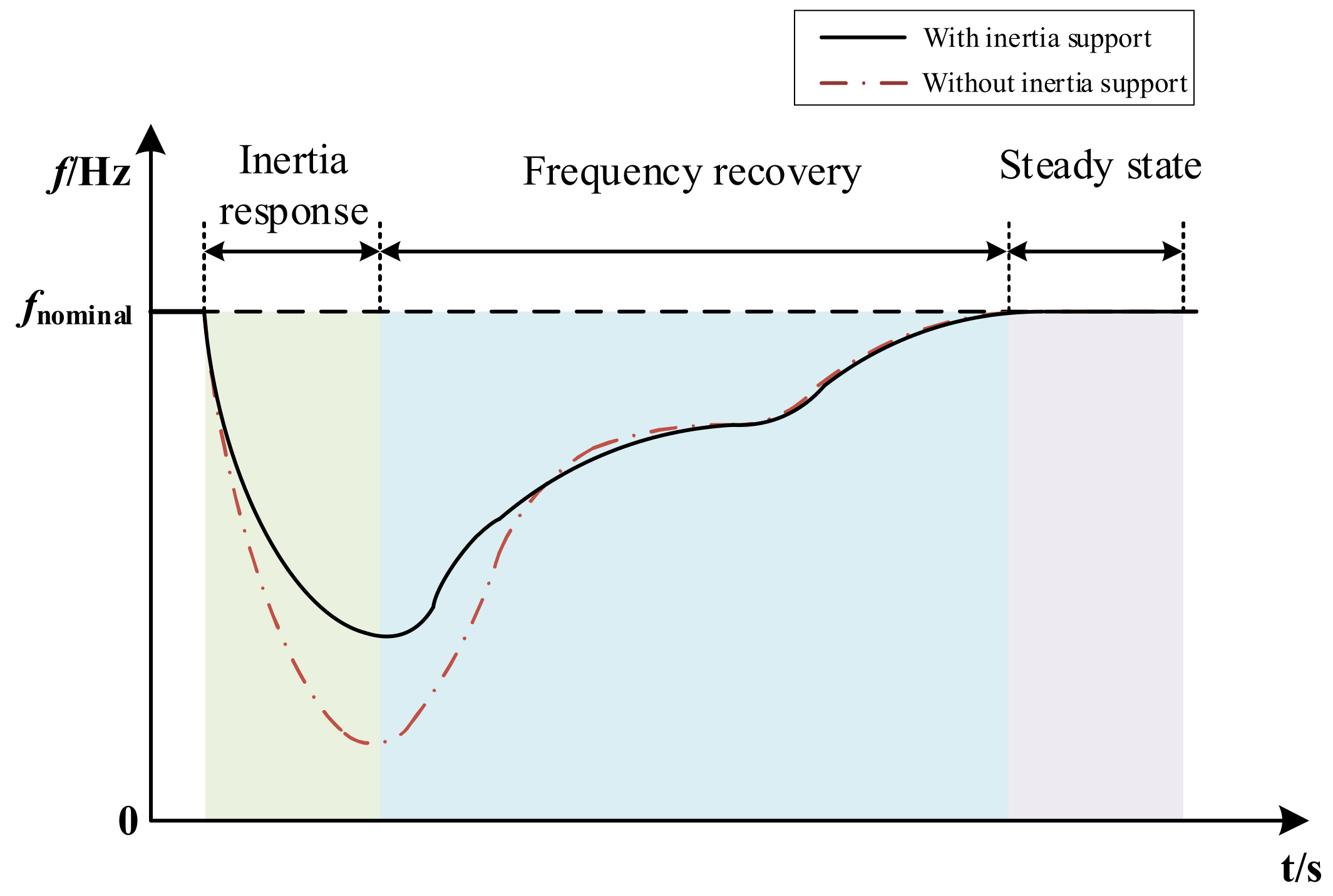
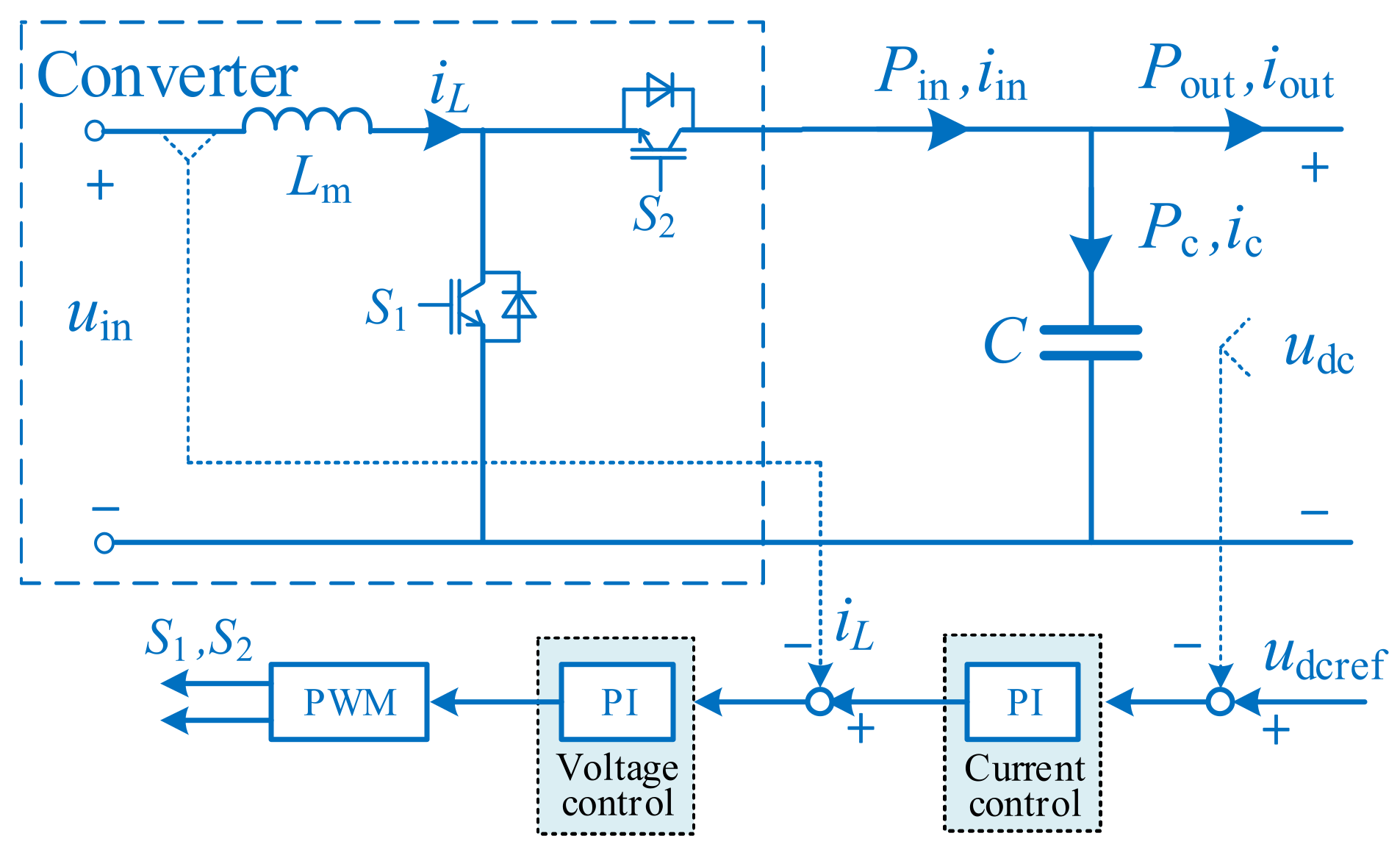
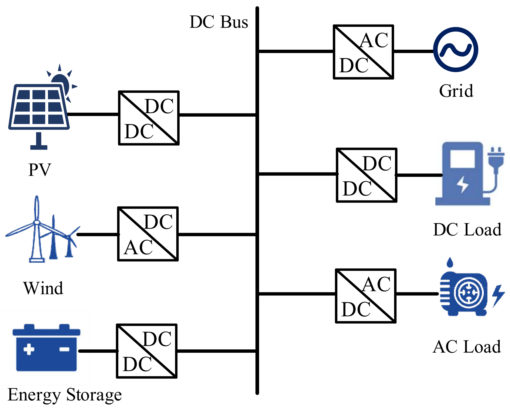
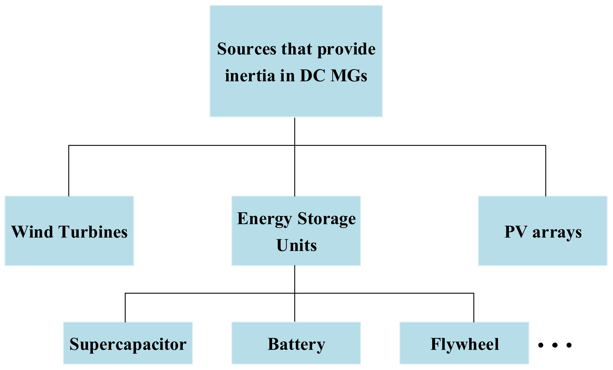
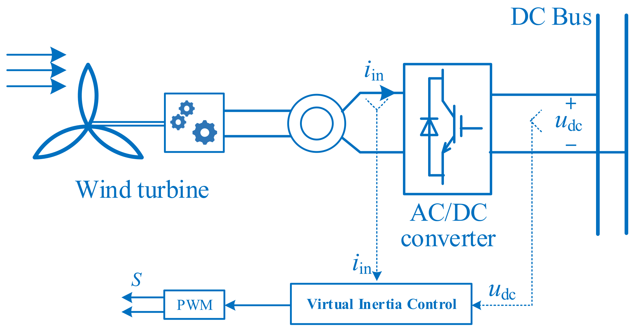
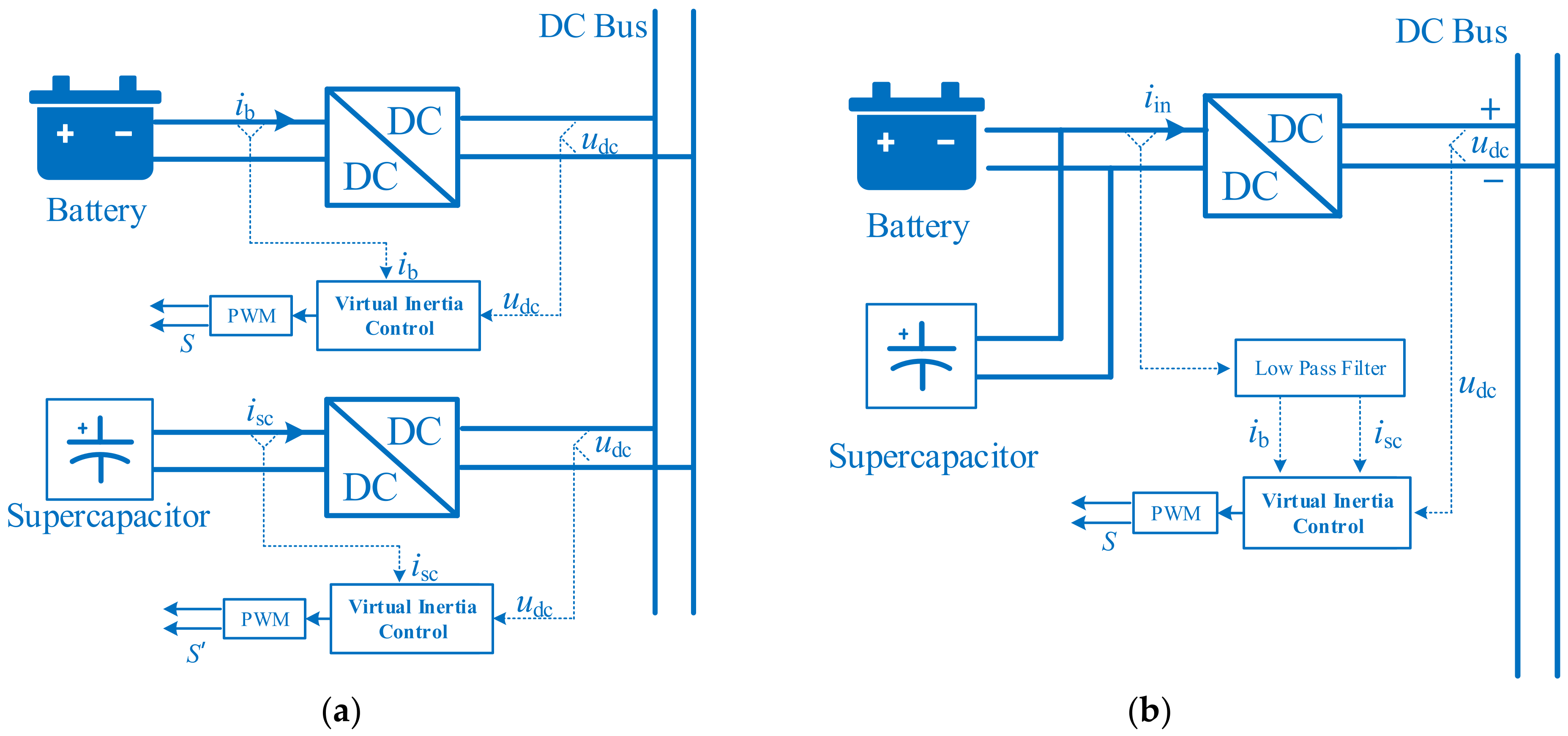
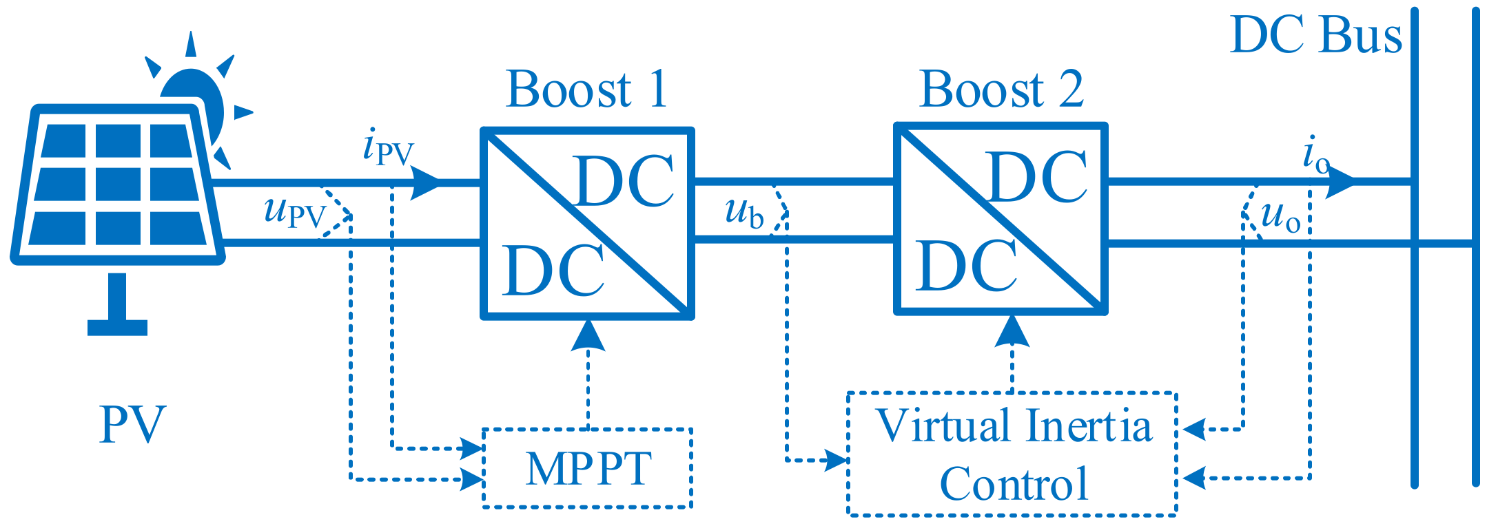
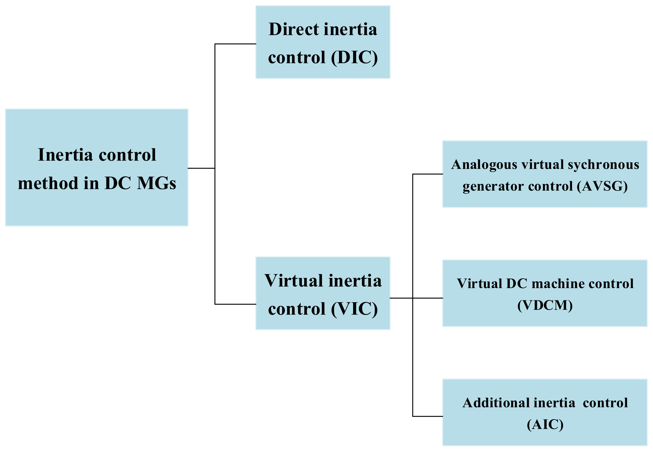
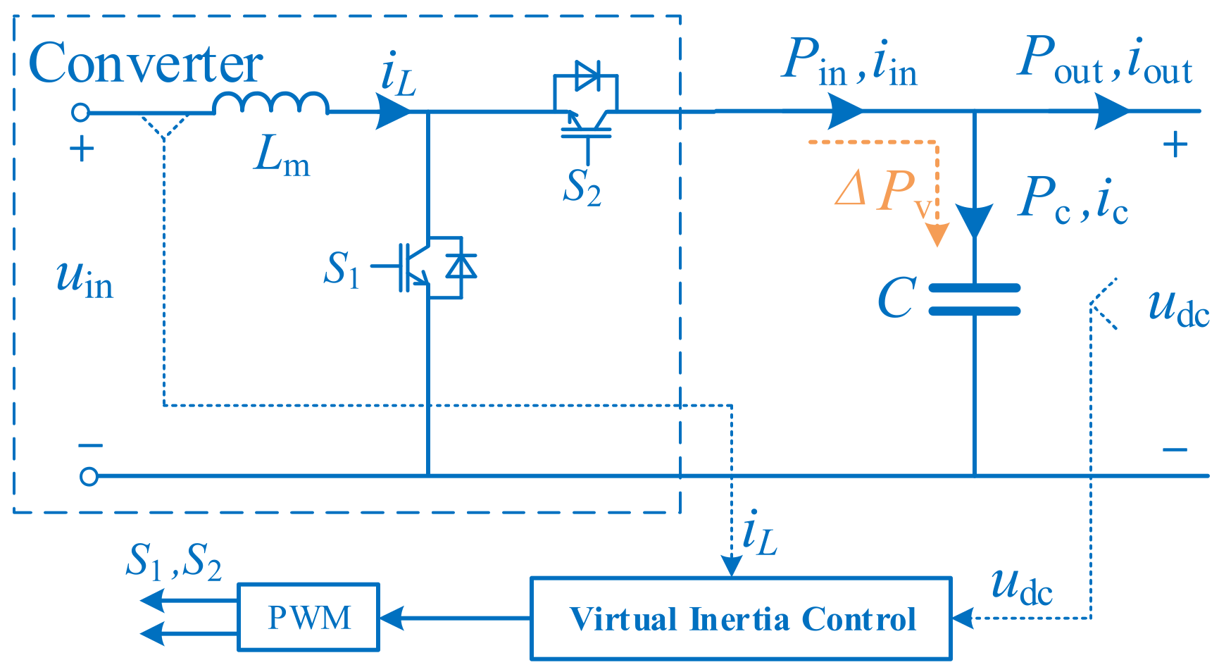
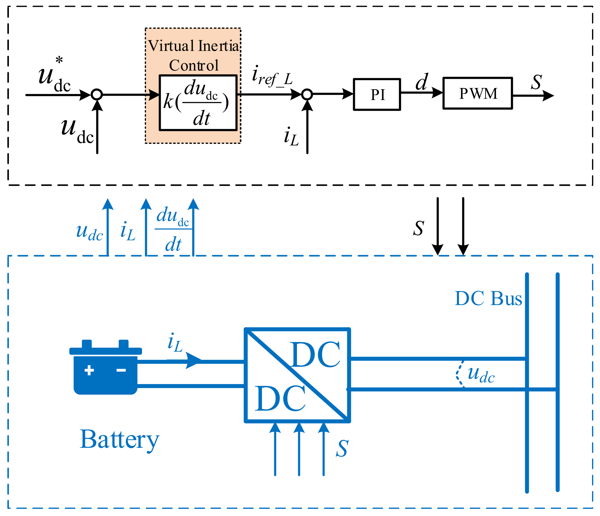
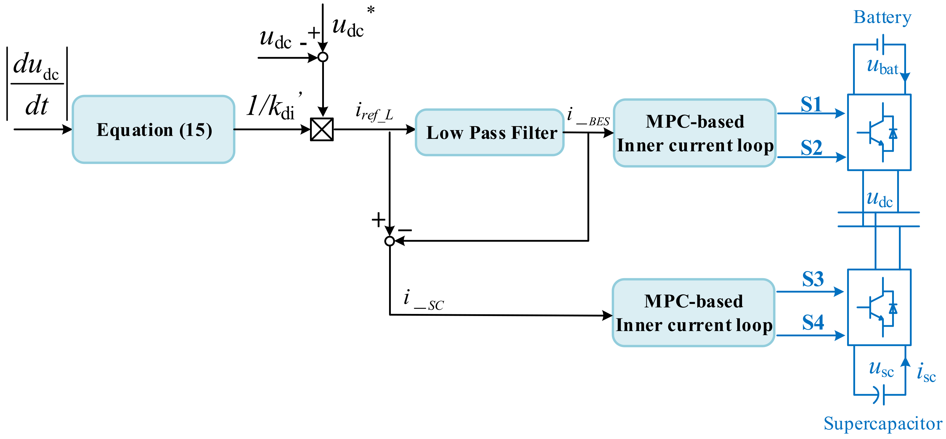
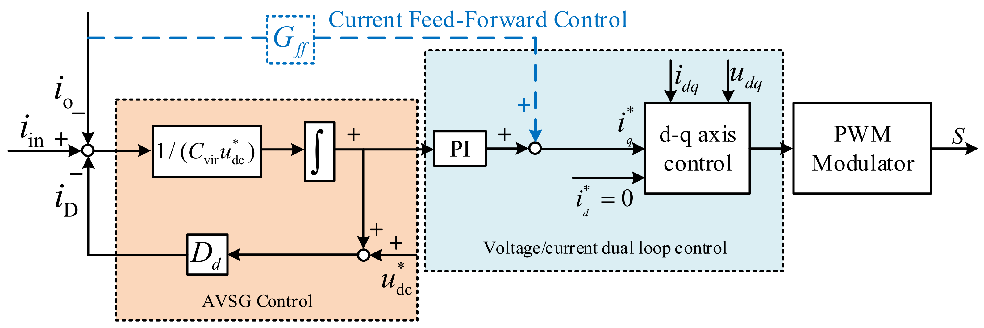
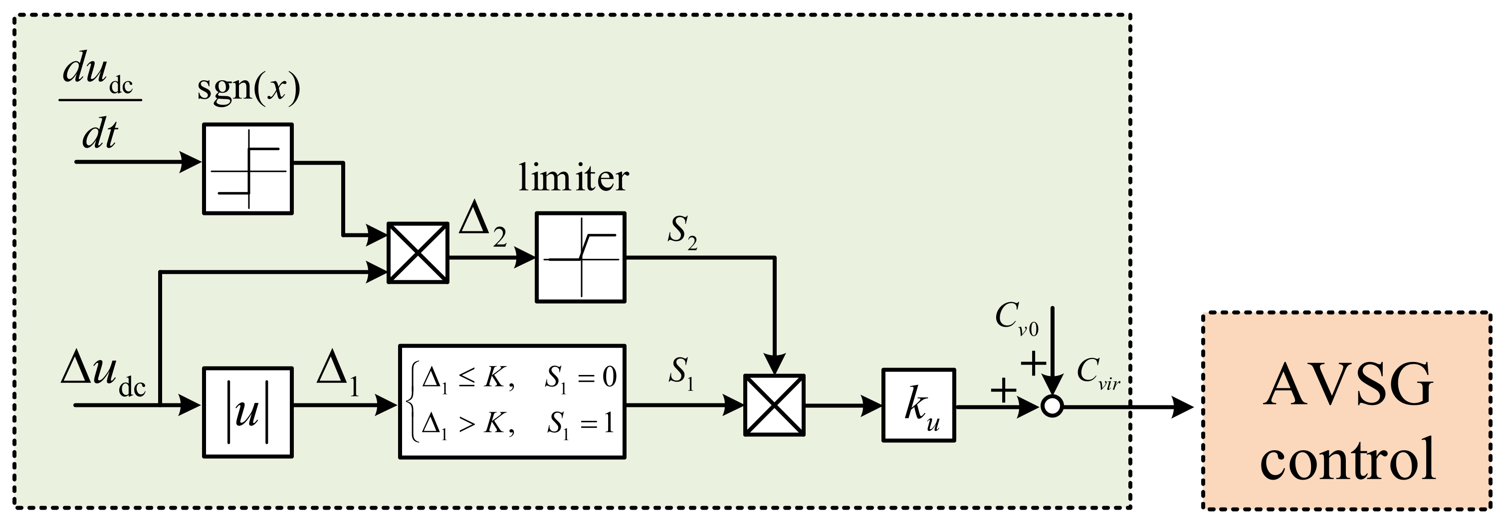
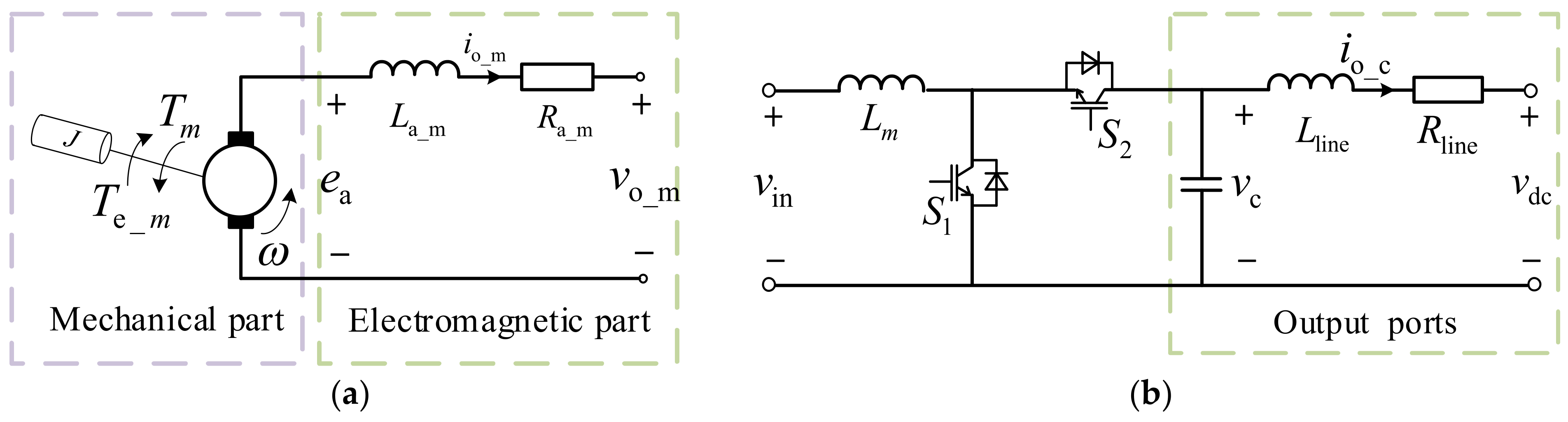
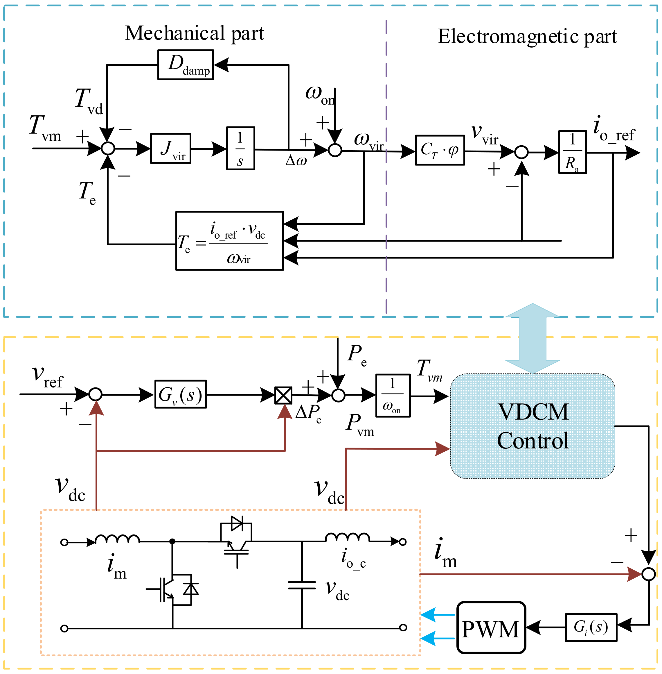
Table 1.
VSG analogy between ac system and dc system.
| Variables | VSG in AC System | VSG in DC System |
|---|---|---|
| Droop relation | ||
| Control objects | ||
| Output | ||
| Inertia | ||
| Storage energy |
Table 2.
Analogy between dc machine and VDCM control.
| Variables | DC Machine | VDCM Control |
|---|---|---|
| Mechanical power | Primary motor | ESS/RES (PV, Wind turbine) |
| Inertia | from rotor | from virtual inertia |
| Induced electric potential | ||
| Output voltage | ||
| Angular frequency | ||
| Armature winding | ||
| Storage energy |
Table 3.
Summary of virtual inertia control methods.
| Control Technique | Advantages | Disadvantages |
|---|---|---|
| AIC |
|
|
| AVSG |
|
|
| VDCM |
|
|
Publisher’s Note: MDPI stays neutral with regard to jurisdictional claims in published maps and institutional affiliations. |
© 2022 by the authors. Licensee MDPI, Basel, Switzerland. This article is an open access article distributed under the terms and conditions of the Creative Commons Attribution (CC BY) license (https://creativecommons.org/licenses/by/4.0/).
Share and Cite
MDPI and ACS Style
Wang, F.; Sun, L.; Wen, Z.; Zhuo, F. Overview of Inertia Enhancement Methods in DC System. Energies 2022, 15, 6704. https://0-doi-org.brum.beds.ac.uk/10.3390/en15186704
AMA Style
Wang F, Sun L, Wen Z, Zhuo F. Overview of Inertia Enhancement Methods in DC System. Energies. 2022; 15(18):6704. https://0-doi-org.brum.beds.ac.uk/10.3390/en15186704
Chicago/Turabian StyleWang, Feng, Lizheng Sun, Zhang Wen, and Fang Zhuo. 2022. "Overview of Inertia Enhancement Methods in DC System" Energies 15, no. 18: 6704. https://0-doi-org.brum.beds.ac.uk/10.3390/en15186704
Note that from the first issue of 2016, this journal uses article numbers instead of page numbers. See further details here.