
Optimal Coordination of Time Delay Overcurrent Relays for Power Systems with Integrated Renewable Energy Sources

Department of Electrical Engineering, King Fahd University of Petroleum and Minerals (KFUPM), Dhahran 31261, Saudi Arabia
*
Author to whom correspondence should be addressed.
†
These authors contributed equally to this work.
Energies 2022, 15(18), 6749; https://0-doi-org.brum.beds.ac.uk/10.3390/en15186749
Submission received: 6 August 2022
/
Revised: 5 September 2022
/
Accepted: 9 September 2022
/
Published: 15 September 2022
(This article belongs to the Special Issue Protection of Future Electricity Systems II)
Abstract
:With the gradual increase in load demand due to population and economic growth, integrating renewable energy sources (RES) into the grid represents a solution for meeting load demand. However, integrating RES might change the power system type from radial to non-radial, where the current can flow forward and backward. Consequently, power system analysis methods must be updated. The impact on power systems includes changes in the load flow affecting the voltage level, equipment sizing, operating modes, and power system protection. Conventional power system protection methods must be updated, as RES integration will change the power flow results and the short circuit levels in the power system. With an RES contribution to short circuit, existing settings might experience missed coordination which will result in unnecessary tripping. This paper considers the impact of integrating renewable energy sources into power system protection on overcurrent time delay settings. A new method to upgrade/adjust time delay settings is developed utilizing genetic algorithm (GA) optimization. The proposed optimization method can be used to evaluate the impact of integrating RES on the exiting overcurrent setting, and can provide new settings without the need to replace existing protection devices when the short circuit is within equipment thermal limits.
1. Introduction
With exponential growth in electrical energy demand due to population and economic growth, renewable energy integration is required to meet load demand and to limit and reduce the impact of conventional generators on global warming [1]. Renewable energy sources (RES) are clean sources that utilize natural resources to produce electricity, dependent on their availability in the environment. RES have zero fossil fuel emissions; thus, utilizing them helps to reduce CO2 emissions, positively impacting global warming. Moreover, RES have different features than conventional synchronous generators, as RES vary in terms of their output power with changes in the environment. In contrast, conventional generators can be controlled by adjusting fuel burning. Unlike conventional generators, RES are location-constrained, as RES output varies from one geographic location to another. Additionally, RES have almost zero operating costs, which is one of their main features [2].
RES sources can be integrated into either transmission systems or distribution systems. Larger-scale power generators (conventional or RES) are connected to transmission systems, while smaller-scale generators are connected to distribution systems [3]. The challenges of integrating RES into transmission and distribution systems are not the same. Transmission systems have a higher voltage level because they are designed to supply loads for long distances. In contrast, distribution systems have lower voltage level and are designed to supply nearby loads [4].
Traditionally, power systems are radial; the real power and reactive power flow from generators to transmission lines, and from transmission lines to the distribution system, and then from the distribution system to the load directly. However, when RES is introduced to transmission and distribution systems, the power might flow on both sides, forward and backward. Due to the change in the power flow, when using RES, power system operation, control, and protection must be updated to cope with changes in the power system [5]. Overall, integrating RES has positive and negative aspects. First, the positive aspects include energy security, reduced pollution, relief in line congestion, reliable power in remote locations, and reduction in CO2 emissions produced by fossil fuel generators, decreasing the impact on global warming. However, it is much more challenging to exploit, and requires more consideration in terms of power system planning and the operation of transmission and distribution systems [5].
A technical study must be performed prior to introducing a high penetration of renewable energy sources to evaluate power system stability and frequency regulation consequences [3]. Further, an economic analysis is required to ensure overall profitability in terms of capital, operation, and maintenance costs. Additional equipment might be added, such as flexible AC transmission systems (FACTS) devices, with significant RES penetration to improve power system operation. Consequently, the overall net cost might increase to a level where integrating RES into the power system is not profitable [3,6,7].
Integrating RES into power systems presents new challenges, including power system flexibility, the requirement for reserve power sources, the need to upgrade or increase the number of transmission line/cables, voltage control (reactive power availability), dynamic stability, reliability, power system quality, frequency control, and power system protection [8,9,10].
- RES integration might change the load flow results. Therefore, transmission lines/distribution cables and voltage at buses must be re-evaluated [3]. Installing FACTS devices, adding more lines with transformers, or expanding the balancing of RES and market connection are solutions proposed to keep steady-state results within acceptable limits [2,8].
- When a high penetration of RES is integrated, the amount of reactive power decreases because conventional generators are disconnected or their output power is output power [1,13]. Adding FACTS devices or using advanced controllers in RES to control the power factor and the reactive power output can support the voltage in the system [14].
- Integrating RES reduces overall network inertia [10]. As a result, frequency stability must be analyzed. It has been proposed to use FACTS devices with RES to compensate for inertia reduction and support frequency stability. In [12], interconnection with other power systems was the solution to support frequency stability.
- As RES penetration increases, there might be a significant reduction in power system reliability in the case of RES loss due to fault or disturbance. Back-up generators and interconnection with other grids should be analyzed to ensure grid reliability [14].
- Since RES are variable and controlled by power electronics devices, power quality might be affected. The addition of filters has been proposed [15] to eliminate harmonics and of storage devices to compensate for frequent changes in RES output.
- IEEE 1547 requires distributed generation to have synchronization parameter limits [16]. An increase in the mismatch between the demand load and generated power creates frequency variation. To reduce this variation, the ramp-up rate of the system should be evaluated, and flexible generators added if required [17].
- RES integration might change the load flow and lead to short circuit. Thus, system studies must be performed prior to integrating RES. Several solutions have been proposed to limit RES impacts on load flow and short circuit, including voltage-based protection, distance protection, directional protection, modifying existing protection schemes, limiting RES capacity, and using fault current limiters [12].
As the power flow and short circuit levels change when there is integration of a high penetration of RES, the protection scheme applicable to power systems using conventional generators must be re-evaluated and updated if required. In [18,19,20], updating the power system protection scheme was discussed and a number of solutions for integrating RES considering power system protection were compared. These included directional overcurrent relay, distance relay, differential relay, adaptive protection, and voltage-based protection. In addition, fault current limiters were proposed in [18] to eliminate the impact of RES on short circuit increments. RES fault contribution was illustrated in [20]. In [21], a distance protection (Device 21) scheme for a DC distribution network was developed and simulated in PSCAD software, and, in [22], distance protection (Device 21) settings were upgraded in terms of the percent of RES in each feeder, and a fuzzy optimization method was utilized. The impact of, and updates required for, directional relays (Device 67) were studied in [22]. Overcurrent protection parameters (Device 51/50) were illustrated in [23,24,25]. In [23], an optimal time delay setting for overcurrent protection was achieved using Lagrange generalized with the Karush–Kuhn–Tucker optimization method, with a constraint of a minimum time delay of 0.3 s; the maximum allowable time delay was based on thermal limits for electrical equipment. However, only one type of time-current curve was used—an IEC time delay curve. In [24], the time delay for overcurrent protection was examined for microgrids based on an interior point optimization method and constraining the time delay curve, with IEEE standard curves only, and the minimum allowable time delay selected to be between 0.2 s and 0.3 s. The study considered only a low-voltage network. In [25], the time delay for an overcurrent relay was re-evaluated after several trippings due to variations in wind turbine output power. The new settings were implemented using electrical transient analyzer program (ETAP) software.
In [26], modification of the existing overcurrent relay setting for a radial system with RES connected to the distribution side was proposed. The modification included replacing the fuse with multi-function relays. Fuses are faster to trip during a short circuit. However, the main disadvantage of fuses is that their curve is fixed and cannot be adjusted, unlike over-current relays. Additionally, in [27], an adaptive method was developed for overcurrent and distance relays. The short circuit contribution was calculated based on an equivalent circuit for the network. An iterative method was utilized for optimization. Finally, in [28], a root tree algorithm was used to determine the optimal overcurrent relay settings. The relay operating time was calculated based only on the standard IEC curve. Time delay setting limitation is considered a constraint and affects the minimum allowable time coordination between relays. The authors of [29] analyzed the performance of different relay curves and used a harmony search algorithm to optimize relay coordination, while [30] proposed relay coordination comparison based on a fuzzy matching method. The authors of [31] proposed optimization for directional overcurrent relay to ensure proper coordination between primary and back-up relays, whereas directional overcurrent relay settings were optimized based on a chaotic cuckoo search algorithm in [32].
Based on the literature review, it appears that the ultimate minimum time delay for an overcurrent relay has not been sufficiently analyzed. The overcurrent protection setting includes steady-state overcurrent pick up (Device 51), instantaneous overcurrent (Device 50), and overcurrent time delay. The main contribution of this paper is the integration of both IEC and IEEE time current curves (TCC) when determining the optimal time delay setting to limit time delay settings between the IEEE Buff Book and thermal limits for electrical equipment/devices, to limit time delay settings based on electrical equipment withstand ratings, and to consider the maximum allowable time delay setting for relays based on vendor design.
The main benefits of the proposed method include the identification of the minimum time delay overcurrent settings and integration of IEEE and IEC time-current curves in the optimization. The constraints for the time settings are as follows: the minimum allowable setting is based on the IEEE Buff Book requirement. In addition, the maximum permissible overcurrent time delay setting considers the thermal limits of all electrical equipment (i.e., power cable, transformer, and switchgear). Table 1 presents a comparison of this investigation with previous studies. It was observed that integrating RES into a power system increases short circuit values in the connected bus. The contribution of renewable energy sources to short circuit vary. For example, squirrel cage induction wind turbine generators (SCIGs), and wound-rotor induction wind turbine generators with variable external rotor resistance (WRIGs) contribute in a similar way to a conventional induction generator. In contrast, full-converter wind turbine generators (WTGs) and solar PVs make a limited contribution due to the existence of power converters. Consequently, the overcurrent time delay settings must be re-evaluated. Furthermore, different vendors will have different relay designs and parameters. Thus, for real-world application, accurate vendor data must be considered.
2. The Impact of RES on Short Circuit Analysis and Relay Setting
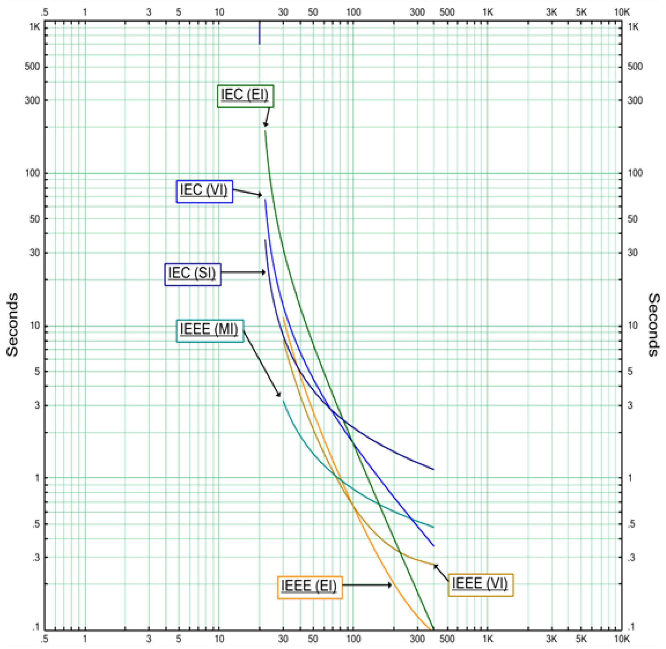
Time coordination is required between primary and secondary protection overcurrent relays. Specifically, it is necessary to ensure the continuous operation of the network in general and ensure that only faulted buses are tripped. Time delay settings for overcurrent relays are based on the maximum short circuit current in the bus. The overcurrent relay curve can vary depending on the selection by the protection engineer. The standard curves include IEC standard inverse time (SI), IEC very inverse time (VI), IEC extremely inverse time (EI), IEEE moderately inverse time (MI), IEEE very inverse time (VI), and IEEE extremely inverse time (EI). In standard relays, all curves are available. The curves have different slopes and shapes. They are primarily selected to protect the thermal limits of the equipment. Figure 1 shows the different standard curves for the same settings [33,34,35].
According to the IEEE Buff Book, static relays should have a minimum 0.2 s coordination time. Different protection devices, such as a fuse, a low voltage circuit breaker, have other minimum coordination times, as shown in Table 2 [35].
Introducing RES to the network will change the short circuit value in the bus, as RES will increase the short circuit value in the connected bus. For instance, SCIG and WRIG wind turbine generators act like induction generators and contribute to the short circuit by around six times full load current. Decoupled RES, such as solar PVs and WTG wind turbines, make only a limited contribution to short circuit up to two times full load current [16].
The change in short circuit current will result in a change in the coordination time, which might lead to miscoordination. The solution to this is to re-evaluate the existing settings ensuring that RES are integrated into the network and short circuit values are changed.
3. Proposed Optimal Time Setting Formulation
This section formulates the optimal settings using genetic algorithm optimization. The objective function, relay operating time formula, the objective function and constraints are explained.
3.1. Objective Function
The objective functions (OF) for the optimization are as follows:
OF1 = Min (tn+1 − tn)
OF2 = Min (TDn+1)
The first objective function, as shown in Equation (1), is to minimize the time delay settings between the main protective relay and backup protection relay to ensure that the main protective relay will trip first and to avoid miscoordination. Secondly, in Equation (2), the backup overcurrent relay time delay setting is optimized as some vendors have a limited range for TD settings. In these equations, tn+1 is the backup overcurrent relay operating time, and tn is the primary overcurrent relay operating time. TD is an overcurrent relay time delay setting.
3.2. Time Current Curve Parameters
Relay operation time can be calculated using either IEEE C37.112 or IEC60255-3 curve constants. Relay operation time can be obtained using Equation (3) [33,34]:
where α, and C are constants which differ depending on the TCC type (as defined in Table 3), I is the operating current, while Is is the steady state overcurrent relay setting.
The protection engineer sets the time delay (TD) as defined in Equation (3). It might start at 0.1, 0.01, or 0.001 based on the manufacturer’s design. Figure 1 depicts all TCC types in one plot, with pick up = 100 A, and TD = 0.5.
3.3. Constraints
Minimum and maximum limits for the time delay setting are considered the main constraints for the objective function.
- Minimum coordination timewhere tn+1 is the backup overcurrent relay operating time, and tn is the primary overcurrent relay operating time. CTI is the clearance time between backup and primary overcurrent relays. CTI is 0.2 s according to the IEEE Buff Book [36].tn+1 − tn ≥ CTI
- The thermal limits for transformer IEEE 57.109 define the thermal constant for three phase transformers rated from 15 to 500 kVA as follows [37], where I is the operating current and t is the duration of the operating current:
- Inrush current and period for the transformer. Suppose the setting must be adjusted due to integrating RES in the system. In that case, the new setting shall not trip during the transformer energization. Thus, the new setting for the primary side of the transformer must be higher than the inrush current period. Iinrush is the transformer’s inrush current during starting, tinrush is the inrush current period for the power transformer, and tsetting is the operating time at the selected overcurrent settings.tinrush(Iinrush) < tsetting(Iinrush)
- Thermal limits for cable. Adjusting the setting should not compromise the thermal limits of the cable, and the cable should be protected at all times. The new setting during short circuit current must be lower than the thermal limits of the cable. According to ANSI/IEEE Std. 141, par. 5.6.2, copper made cables, the thermal limits are as follows [36], where A is the cable size in metric:1432(A)2 ≥ I2 (toperating)
For made cables, the thermal limits are as follows:
942(A)2 ≥ I2 (toperating)
Meanwhile, for aluminum
- Thermal limits for LV switchgear
Standard short circuit ratings for LV switchgear are 50 kA, 65 kA, 85 kA, and 100 kA, and the minimum withstand time is 30 cycles, as per UL 1558. After adjusting the settings due to integrating RES, the new time delay setting multiplied by the short circuit current square must be lower than the switchgear thermal limit [38].
- Thermal limits for HV switchgear
As with LV switchgear, HV switchgear must be checked with respect to its thermal limits during short circuit. Standard short circuit ratings for HV switchgear are 25 kA, 40 kA, and 60 kA, and the minimum withstand time is three cycles according to IEEE Buff Book 242 Section 9.8.3.3. [35].
- Vendor limits for maximum setting for time delay
The range and step of the TD setting vary depending on the vendor design. Table 4 highlights three vendors with different TD range and step values.
4. Results and Discussion
This section explains the case study used to verify the effectiveness of the proposed bi-objective optimizations. First, the network is described. Then, the scenarios used are described, and new settings are proposed for implementation due to RES integration.
Finally, the main observations are highlighted.
RES is assumed to be connected to bus 36 (2.4 kV). The pre-fault setting for the vertical protection system is shown in Table 5. Table 6 highlights the evaluation of the setting.
4.1. System Description
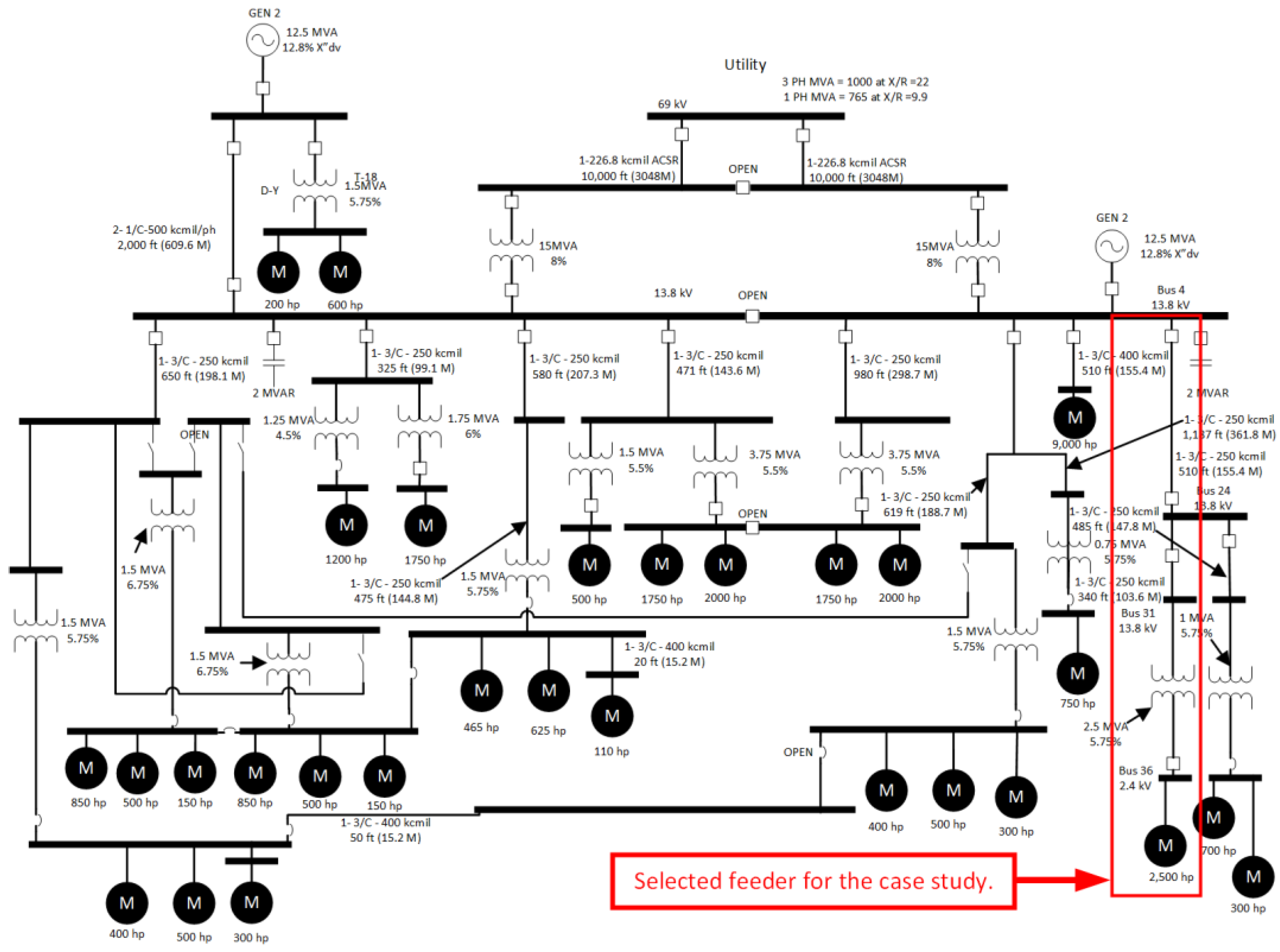
The IEEE 42 bus network defined in the IEEE Brown Book (IEEE Std. 399-1997) and IEEE 242 Buff (IEEE std. 242-2001) is the sample network used in the case study to verify the proposed formulation.
In the IEEE 42 single line diagram, bus 36 is the proposed bus for integrating RES, as depicted in Figure 2. The network has five voltage levels: 69 kV, 13.8 kV, 4.16 kV, 4.2 kV, and 0.48 kV. The network has two types of power sources, which are the utility and local generator. The utility supplies the network through two 69/13.8 kV step-down transformers rated at 15 MVA each. In addition, two local generators (13.28 MW, 13.8 kV) are connected to 13.8 kV switchgear. The network has 42 buses and 21 loads. The most significant 0.48 kV load is connected to bus 17. IEEE bus 42 has a total load of 22 MW. It is assumed that the power flow, short circuit, and relay settings were applied before integrating RES and implementing the proposed formulation. It is assumed that RES is connected to bus 36 (2.4 kV). The pre-fault setting for the vertical protection system is shown in Table 5, which highlights the evaluation of the setting.
4.2. Scenarios and Results
Two case studies are considered to evaluate the effectiveness of the proposed method. The first case (case A) includes wind turbine generator integration, while the second case (case B) covers solar PV integration.
4.2.1. Case A: Wind Turbine Generators Integrated in One Bus at a Time
The first case (A) considers the integration of a WRIG wind turbine generator into bus 36. The wind turbine rating is 2.2 MW, representing 10% penetration of the total network loads for high-voltage buses. Table 7 highlights the maximum wind turbine contribution for each scenario.
WRIG wind turbine 2 is considered to be integrated into bus 36, and the contributed short circuit current is 4.4 kA, which is the increment in short circuit current in the bus compared to the normal case (before RES integration). Integrating 2.2 wind turbines into bus 36 will increase the short circuit current by 33%. The effect mainly occurs in bus 36 coordination with upstream relays. Table 8 shows the changes in short circuit current for each relay, and Table 9 shows the new coordination times. Finally, Table 10 highlights the proposed new settings for three different vendors.
Based on the new increased short circuit, the time coordination between the relays is reduced. Thus, there is an outgoing miscoordination between relay 36 and relay 24. Using the proposed optimal formulation in Matlab code to upgrade the setting, new settings are proposed in Table 8. Four settings for relay 36 are shown in Table 5. The first is the old setting, and the other three are the proposed settings for different vendors, with varying time steps for the TD setting.
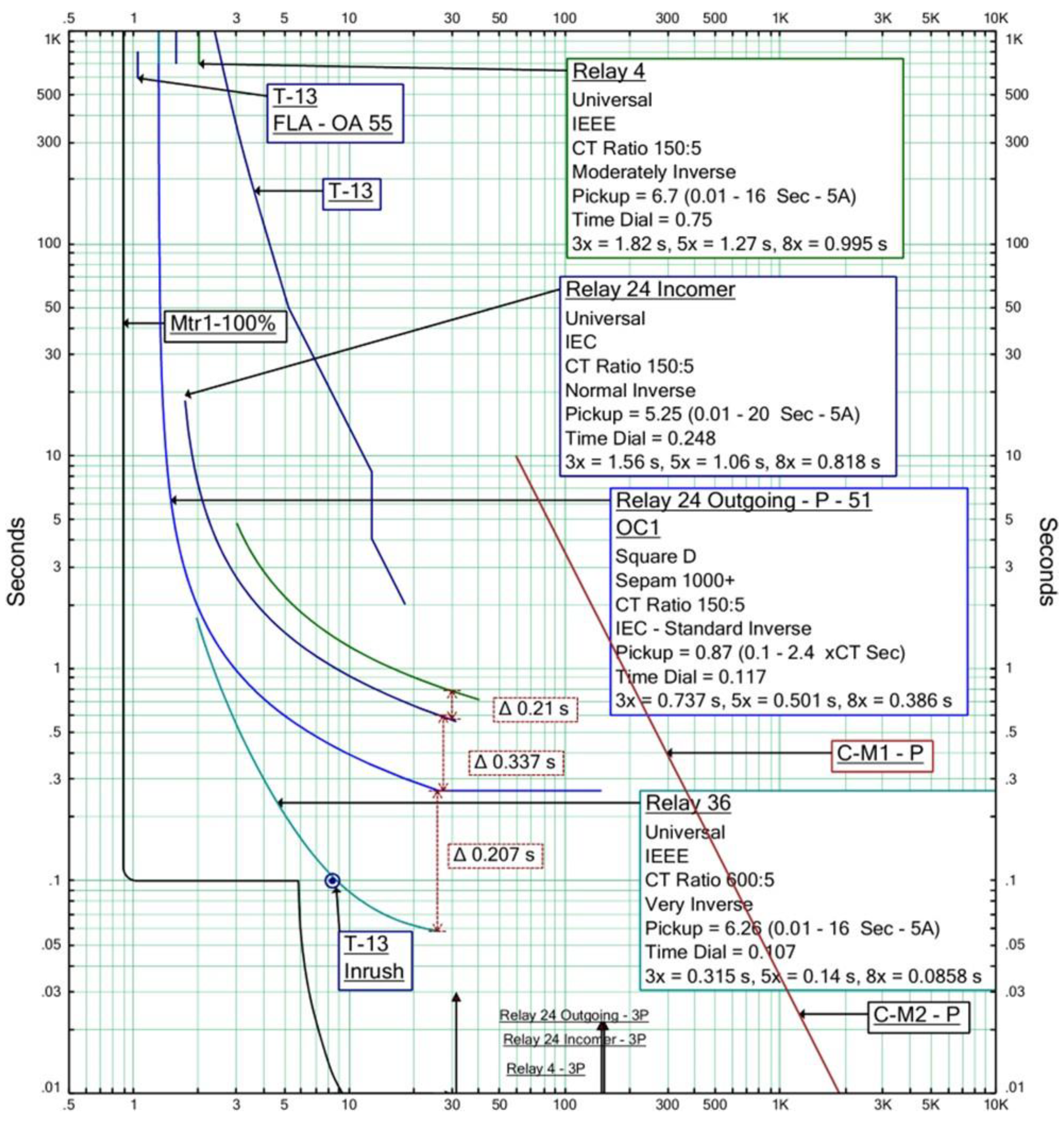
As highlighted in Table 9, the coordination between relay 36 and relay 24 outgoing does not meet the IEEE Buff Book requirement of having a coordination time higher than 0.2 s. The integration of the wind turbine and increase in short circuit current results in a coordination of 0.191 s. To adjust the settings, three different relays from different vendors are considered. Each relay has a different step delay time, starting with manufacturer 1, which has three decimal steps in time delay, to manufacturer 3 relay, which has only one decimal step in time delay. Since accuracy varies among vendors, using each vendor’s relay, the type of curve and the time delay setting proposed to correct the setting are different, as shown in Table 10. The TCC for the proposed setting for manufacturer 1 is show in Figure 3. The setting for bus 24 (relay 24 outgoing) is changed from (TD: 0.47, TCC type IEEE Very Inverse Time VI) to (TD: 0.12, IEC Standard Inverse Time SI).
4.2.2. Case B: Solar PVs Integrated in One Bus at a Time
The integration of a wind–solar PV in bus 36 is considered as the second scenario. The solar panel rating is 2.2 MW, representing a 10% penetration of the total network loads (10% × 22 MW = 2.2 MW). The short circuit for the 2.2 MW solar PV is highlighted in Table 11.
There is no significant impact of integrating 10% penetration of the solar PV, as the contributed short circuit is much smaller than the actual short circuit in the bus. As the solar PV is connected to the system by a power electronics device (convertor), its contribution to the short circuit is minimal.
4.3. Discussion
Overall, integrating distribution generators will increase the short circuit. In the event the distribution generator is a synchronous generator, the short circuit contribution will be quite significant, around six times the full-load current. If the distribution generator is a renewable power source, the contribution will vary. For example, SCIG and WRIG wind turbines will contribute in the same way as an induction generator, while WTG wind turbines and solar PVs will have a limited contribution due to power converters.
In all cases except case B, there was a significant change in the short circuit, and thus the coordination between the relay, whereas in case B, there was no substantial change since the type of integrated renewable energy was a solar PV.
Different vendors have different designs and parameters. For instance, manufacturer 1 relay has three decimal time delay settings, manufacturer 2 has two decimal time delay settings, and manufacturer 3 has only one-time delay setting. This change affected the selected curve type and time delay. For manufacturer 1, the proposed curve type is IEC SI, as IEC SI has the highest multiplier with TD.
5. Conclusions
In conclusion, RES are intermittent, variable, and weather dependent. RES integration has many advantages, such as providing alternative power sources that are not polluting and reducing global warming. However, a technical study must be performed prior to integrating a high penetration of renewable energy sources to evaluate the impact on power systems. Moreover, an economic analysis is required to ensure overall profitable investment in terms of capital, operation, and maintenance costs. At the same time, the integration of RES creates many challenges in power system planning and operation. These challenges mainly relate to power system flexibility, the requirement for reserve power sources, the requirement to upgrade or increase the number of transmission line/cables, voltage control (reactive power availability), dynamic stability, reliability, power system quality, frequency control, and power system protection.
Integrating RES in power systems increases the short circuit level in the connected bus and nearby buses. The RES contribution to short circuit depends on the RES type. As shown in the case study, the WRIG wind turbine increased the short circuit value significantly, while the solar PV had a minimal effect. Power system protection was investigated in more detail, and it was found that the ultimate minimum TD for overcurrent relays has not been thoroughly analyzed. The ultimate minimum TD for overcurrent protection considering high RES penetration was investigated, and GA optimization was provided to ensure proper coordination between the relays, considering the high penetration, which impacted the short circuit current at the connected bus. A constraint to this optimization is limitation of the overcurrent TD between relays, according to the IEEE Buff Book requirement. In addition, thermal limits for electrical equipment, including power cables, transformers, and switchgear, were considered limits for the maximum allowable setting. Different decimals for setting the TDs were considered based on three different vendors. With this formulation and optimization code, power system coordination can be improved when RES are integrated. Even in circumstances of lower RES output power and short circuit contribution, the proposed formulation will still ensure proper coordination between the main protective device and the back-up protective device with some time delay in case of lower short circuit. The proposed optimization method in this paper can be used to evaluate the impact of integrating RES on exiting the overcurrent setting, and it can provide new settings without the need to replace existing protection devices when the short circuit is within equipment thermal limits. As shown in the case study (Table 8, Table 9 and Table 10), using the proposed method, the settings for (24 outgoing relay) were changed without the need to replace the relay. Three different settings were proposed in Table 10 considering three different manufacturers. The operation time during a miss-coordination scenario (Table 8) 0.246 s was upgraded to 0.256 s or 0.264 s, as indicated in Table 10, with different TCC types to ensure maintenance of an allowable clearing time between primary and pick-up relays. Future work will include evaluation of the impact of coordinating overcurrent relays and fuses or low voltage circuit breakers.
Author Contributions
Conceptualization, M.A.T. and M.A.-M.; methodology, M.A.T.; software, M.A.T. and M.A.-M.; validation, M.A.T. and M.A.-M.; formal analysis, M.A.T. and M.A.-M.; investigation, M.A.T. and M.A.-M.; resources, M.A.T. and M.A.-M.; data curation, M.A.T.; writing—original draft preparation, M.A.-M.; writing—review and editing, M.A.T. and M.A.-M.; visualization, M.A.-M.; supervision, M.A.-M.; project administration, M.A.-M.; funding acquisition, M.A.T. and M.A.-M. All authors have read and agreed to the published version of the manuscript.
Funding
This research received no external funding.
Institutional Review Board Statement
Not applicable.
Informed Consent Statement
Not applicable.
Data Availability Statement
Not applicable.
Acknowledgments
The authors acknowledge the support of the King Fahd University of Petroleum and Minerals (KFUPM), Dhahran, Saudi Arabia.
Conflicts of Interest
The authors declare no conflict of interest.
Abbreviations
The following abbreviations are used in this manuscript:
| CTI | Clearance time interval |
| FACTS | Flexible AC transmission systems |
| GA | Genetic algorithm |
| Iinrush | Inrush current for power transformer |
| Is | Pick steady state current setting for the relay |
| I | Operating current sensed by CT |
| K, α, C | Constant values based on standard |
| TCC | curve types |
| PV | Photovoltaic |
| RES | Renewable energy sources |
| SCIG | Squirrel cage induction wind turbine generator |
| TCC | Time current curve |
| TDn+ | Back-up overcurrent relay time delay setting |
| tn | Primary overcurrent relay operating time |
| tn+1 | Back-up overcurrent relay operating time |
| tmax | The maximum withstand time for the equipment during short circuit |
| tinrush | Inrush current period for power transformer |
| WRIG | Wind turbine generator with variable external rotor resistance |
| WTG | Full-converter wind turbine generator |
References
- 3002.2-2018; IEEE Recommended Practice for Conducting Load-Flow Studies and Analysis of Industrial and Commercial Power Systems. IEEE: Piscataway, NJ, USA, 2018; pp. 1–73. [CrossRef]
- Saudy Electricity Company. The Saudi Arabian Grid Code Electronic; Saudy Electricity Company: Riad, Saudi Arabia, 2016. [Google Scholar]
- Pratheeksha, R.; Kavitha, K.M. Analysis of STATCOM, SVC and UPFC FACTS devices for transient stability improvement in power system. Int. J. Sci. Res. 2016, 5, 1207–1210. [Google Scholar]
- Shen, S.; Lin, D.; Wang, H.; Hu, P.; Jiang, K.; Lin, D.; He, B. An adaptive protection scheme for distribution systems with DGs based on optimized thevenin equivalent parameters estimation. IEEE Trans. Power Deliv. 2015, 32, 411–419. [Google Scholar] [CrossRef]
- Al Talaq, M.; Belhaj, C.A. Optimal PV penetration for power losses subject to transient stability and harmonics. Procedia Comput. Sci. 2020, 175, 508–516. [Google Scholar] [CrossRef]
- Nikolaidis, V.C.; Papanikolaou, E.; Safigianni, A.S. A Communication-assisted overcurrent protection scheme for radial distribution systems with distributed generation. IEEE Trans. Smart Grid 2015, 7, 114–123. [Google Scholar] [CrossRef]
- Dubey, R.; Samantaray, S.R.; Panigrahi, B.K. Adaptive distance protection scheme for shunt-FACTS compensated line connecting wind farm. IET Gener. Transm. Distrib. 2016, 10, 247–256. [Google Scholar] [CrossRef]
- Sandhu, M.; Thakur, T. Issues, challenges, causes, impacts and utilization of renewable energy sources—Grid integration. J. Eng. Res. Appl. 2014, 4, 636–643. [Google Scholar]
- Sinsel, S.R.; Riemke, R.L.; Hoffmann, V.H. Challenges and solution technologies for the integration of variable renewable energy sources—A review. Renew. Energy 2020, 145, 2271–2285. [Google Scholar] [CrossRef]
- Karki, S.U.; Halbhavi, S.B.; Kulkarni, S.G. Study on challenges in integrating renewable technologies. Int. J. Adv. Res. Electr. Electron. Instrum. Eng. 2014, 3, 10972–10977. [Google Scholar]
- Achilles, S.; Schramm, S.; Bebic, J. Transmission system performance analysis for high-penetration photovoltaics; NREL/SR-581-42300; National Renewable Energy Laboratory: Golden, CO, USA, 2008; 2, p. 13.
- Telukunta, V.; Pradhan, J.; Agrawal, A.; Singh, M.; Srivani, S.G. Protection challenges under bulk penetration of renewable energy resources in power systems: A review. CSEE J. Power Energy Syst. 2017, 3, 365–379. [Google Scholar] [CrossRef]
- Saadat, H. Power Systems Analysis; McGraw-Hill Primis Custom Pub.: Boston, MA, USA, 2002. [Google Scholar]
- Malley, M.O. Grid Integration of Variable Renewable Energy Sources: Research Challenges and Opportunities. Networks 2011. [Google Scholar]
- Vidyanandan, K.V.; Balkrishn, K. Grid integration of renewables: Challenges and solutions. In Proceedings of the 2018 7th International Conference on Renewable Energy Research and Applications (ICRERA), Paris, France, 14–17 October 2018. [Google Scholar] [CrossRef]
- Muljadi, E.; Samaan, N.; Gevorgian, V.; Li, J.; Pasupulati, S. Short circuit current contribution for different wind turbine generator types. In Proceedings of the IEEE PES General Meeting, Minneapolis, MN, USA, 25–29 July 2010; pp. 1–8. [Google Scholar]
- Stewart, E.; MacPherson, J.; Vasilic, S.; Nakafuji, D.; Aukai, T. Analysis of High-Penetration Levels of Photovoltaics into the Distribution Grid on Oahu, Hawaii: Detailed Analysis of HECO Feeder WF1; National Renewable Energy Laboratory: Golden, CO, USA, 2013; p. 42.
- Norshahrani, M.; Mokhlis, H.; Abu Bakar, A.H.; Jamian, J.J.; Sukumar, S. Progress on protection strategies to mitigate the impact of renewable distributed generation on distribution systems. Energies 2017, 10, 1864. [Google Scholar] [CrossRef]
- Senarathna, T.S.S.; Hemapala, K.T.M.U. Review of adaptive protection methods for microgrids. AIMS Energy 2019, 7, 557–578. [Google Scholar] [CrossRef]
- Ola, S.R.; Saraswat, A.; Goyal, S.K.; Jhajharia, S.K.; Khan, B.; Mahela, O.P.; Alhelou, H.H.; Siano, P. A protection scheme for a power system with solar energy penetration. Appl. Sci. 2020, 10, 1516. [Google Scholar]
- Jia, K.; Zhao, Q.; Feng, T.; Bi, T. Distance protection scheme for DC distribution systems based on the high-frequency characteristics of faults. IEEE Trans. Power Deliv. 2019, 35, 234–243. [Google Scholar] [CrossRef]
- Singh, M.; Telukunta, V. Adaptive distance relaying scheme to tackle the under reach problem due renewable energy. In Proceedings of the 18th National Power Systems Conference, Guwahati, India, 18–20 December 2014; pp. 3–8. [Google Scholar]
- Keil, T.; Jager, J. Advanced coordination method for overcurrent protection relays using nonstandard tripping characteristics. IEEE Trans. Power Deliv. 2007, 23, 52–57. [Google Scholar] [CrossRef]
- Alam, M.N.; Gokaraju, R.; Chakrabarti, S. Protection coordination for networked microgrids using single and dual setting overcurrent relays. IET Gener. Transm. Distrib. 2020, 14, 2818–2828. [Google Scholar] [CrossRef]
- Ok, Y.; Lee, J.; Choi, J. Coordination of over current relay for sudden rise of input energy in renewable power system. In Proceedings of the International Conference on Renewable Energy Research and Applications, Palermo, Italy, 22–25 November 2015; Volume 5, pp. 654–658. [Google Scholar]
- Funmilayo, H.B.; Butler-Purry, K.L. An approach to mitigate the impact of distributed generation on the overcurrent protection scheme for radial feeders. In Proceedings of the IEEE/PES Power Systems Conference and Exposition, Seattle, WA, USA, 15–18 March 2009; pp. 1–11. [Google Scholar]
- Ojaghi, M.; Sudi, Z.; Faiz, J. Implementation of full adaptive technique to optimal coordination of overcurrent relays. IEEE Trans. Power Deliv. 2012, 28, 235–244. [Google Scholar] [CrossRef]
- Wadood, A.; Gholami Farkoush, S.; Khurshaid, T.; Kim, C.-H.; Yu, J.; Geem, Z.W.; Rhee, S.-B. An optimized protection coordination scheme for the optimal coordination of overcurrent relays using a nature-inspired root tree algorithm. Appl. Sci. 2018, 8, 1664. [Google Scholar] [CrossRef]
- Vala, T.M.; Rajput, V.N.; Joshi, K.; Guha, D. Effect of relay characteristics in optimum coordination of overcurrent relays. In Proceedings of the 2020 IEEE Students Conference on Engineering Systems (SCES), Prayagraj, India, 10–12 July 2020; pp. 1–6. [Google Scholar] [CrossRef]
- Shi, F.; Yang, C.; Liu, M.; Fan, R. Research and application on the relay protection setting comparison system based on fuzzy matching. In Proceedings of the 2020 IEEE 4th Conference on Energy Internet and Energy System Integration (EI2), Wuhan, China, 30 October–1 November 2020; pp. 2119–2123. [Google Scholar] [CrossRef]
- Jabir, H.A.; Kamel, S.; Selim, A.; Jurado, F. Optimal coordination of overcurrent relays using metaphor-less simple method. In Proceedings of the 2019 21st International Middle East Power Systems Conference (MEPCON), Cairo, Egypt, 17–19 December 2019; pp. 1063–1067. [Google Scholar] [CrossRef]
- Biswal, S.; Sharma, N.K.; Samantaray, S.R. Optimal overcurrent relay coordination scheme for microgrid. In Proceedings of the 2020 21st National Power Systems Conference (NPSC), Gandhinagar, India, 17–19 December 2020; pp. 1–6. [Google Scholar] [CrossRef]
- C37.112-2018; IEEE Standard for Inverse-Time Characteristics Equations for Overcurrent Relays. IEEE: Piscataway, NJ, USA, 2019. [CrossRef]
- IEC 0255-3; Electrical Relays—Part 3: Single Input Energizing Quantity Measuring Relays with Dependent of Independent Time. IEEE: Piscataway, NJ, USA, 1989.
- 242-2001; IEEE Recommended Practice for Protection and Coordination of Industrial and Commercial Power Systems (IEEE Buff Book). IEEE: Piscataway, NJ, USA, 2001. [CrossRef]
- Std 141-1993; IEEE Recommended Practice for Electric Power Distribution for Industrial Plants. IEEE: Piscataway, NJ, USA, 1994. [CrossRef]
- Std C57.109-1993; IEEE Guide for Liquid-Immersed Transformers Through-Fault-Current Duration. IEEE: Piscataway, NJ, USA, 2018. [CrossRef]
- C37.20.1-1993; IEEE Standard for Metal-Enclosed Low-Voltage Power Circuit Breaker Switchgear. IEEE: Northbrook, IL, USA, 1993.
Figure 1.
Standard overcurrent curves.

Figure 2.
Single line diagram for IEEE bus 42.

Figure 3.
The proposed setting for manufacturer 1.


Table 1.
Comparison of this investigation and previous studies.
| Ref No. | Optimization Method | TCC Types | Constraints |
|---|---|---|---|
| [23] | Lagrange generalized with the Karush–Kuhn–Tucker optimization method. | Only IEC time delay curve | Thermal limits for electrical equipment |
| [24] | Interior point optimization method | IEEE standard curves only | - |
| [28] | Root tree algorithm | Standard IEC curve | - |
| [29] | Harmony search algorithm | Different relay curves | - |
| This paper | GA Optimization | Both IEC and IEEE standard curves | Thermal limits for all electrical equipment including switchgears, cables, and transformers. In addition, transformer inrush current for power transformer. |
Table 2.
IEEE Buff Book minimum clearing time [35].
Table 2.
IEEE Buff Book minimum clearing time [35].
| Downstream/Upstream | Fuse | LV CB | Electromechanical Relay | Static Relay |
|---|---|---|---|---|
| Fuse | CS | CS | 0.22 s | 0.12 s |
| LV CB | CS | CS | 0.22 s | 0.12 s |
| Electromechanical relay | 0.2 s | 0.2 s | 0.3 s | 0.2 s |
| Static relay | 0.2 s | 0.2 s | 0.3 s | 0.2 s |
CS: Clear space; LV CB: Low voltage circuit-breaker.
| Type of Curve | K | C | α |
|---|---|---|---|
| IEC Standard Inverse Time (SI) | 0.14 | 0 | 0.02 |
| IEC Very Inverse Time (VI) | 13.5 | 0 | 1 |
| IEC Extremely Inverse Time (EI) | 80 | 0 | 2 |
| IEEE Moderately Inverse Time (MI) | 0.0515 | 0.114 | 0.02 |
| IEEE Very Inverse Time (VI) | 19.61 | 0.491 | 2 |
| IEEE Extremely Inverse Time | 28.2 | 0.1217 | 2 |
Table 4.
TD range based on manufacturer design.
| Manufacturer Name | Model Number | Min | Max | Step |
|---|---|---|---|---|
| Manufacturer 1 | Model Number 1 | 0.001 | 15.47 | 0.001 |
| Manufacturer 2 | Model Number 2 | 0.01 | 600 | 0.01 |
| Manufacturer 3 | Model Number 3 | 0.1 | 10 | 0.1 |
Table 5.
Pre-fault overcurrent relay settings.
| KV | Bus No. | TCC Type | TD | Isetting | Isc | t |
|---|---|---|---|---|---|---|
| 2.4 | 36 | IEEE Very | 0.107 | 751.2 | 13627 | 0.06 |
| Inverse Time | ||||||
| (VI) | ||||||
| 13.8 | 31 | IEEE Very | 0.47 | 131.1 | 2369.9 | 0.26 |
| Inverse Time | ||||||
| (VI) | ||||||
| 13.8 | 24 | IEC Standard | 0.241 | 157.5 | 2369 | 0.61 |
| Inverse Time | ||||||
| (SI) | ||||||
| 13.8 | 4 | IEEE | 0.719 | 210 | 2369.9 | 0.83 |
| Moderately Inverse time (MI) |
Table 6.
Time delay for overcurrent relays before the fault.
| Back Up Relay No. | Primary Relay No. | Time Delay | |
|---|---|---|---|
| 36 | 31 | 0.200 | Acceptable |
| 31 | 24 | 0.346 | Acceptable |
| 24 | 4 | 0.222 | Acceptable |
Table 7.
Short circuit contribution for wind turbine.
| Scenarios | kV | Bus No. | Wind Turbine Rating (MW) | Type | IFL (A) | Isc (A) |
|---|---|---|---|---|---|---|
| A | 2.4 | 36 | 2.2 | 2 |
Table 8.
Case A1 setting.
| KV | Bus No. | TCC Type | TD | Isetting | Isc | t |
|---|---|---|---|---|---|---|
| 2.4 | 36 | IEEE Very Inverse Time (VI) | 0.107 | 751.2 | 18079 | 0.056 |
| 13.8 | 24 | IEEE Very | 0.47 | 131.1 | 3144 | 0.246 |
| outgoing | Inverse Time (VI) | |||||
| 13.8 | IEC Standard | 0.241 | 157.5 | 3144 | 0.546 | |
| 24 | Inverse Time (SI) | |||||
| incomer | IEEE | 0.719 | 210 | 3144 | 0.747 | |
| 13.8 | 4 | Moderately Inverse time (MI) |
Table 9.
Time delay for overcurrent relays during the fault.
| Back Up Relay No. | Primary Relay No. | Time Delay |
|---|---|---|
| 36 | 24 outgoing | 0.191 |
| 24 outgoing | 24 incoming | 0.300 |
| 24 incoming | 4 | 0.201 |
Table 10.
Proposed new settings for case A1.
| KV | Bus No. | TCC Type | TD | t | Vendor Name |
|---|---|---|---|---|---|
| 2.4 | 36 | IEEE Very Inverse Time (VI) | 0.107 | 0.056 | |
| 13.8 | 24 outgoing | IEEE Very Inverse Time (VI) | 0.47 | 0.47 | |
| 13.8 | 24 outgoing | IEC Standard Inverse Time (SI) | 0.120 | 0.256 | manufacturer 1 |
| 13.8 | 24 outgoing | IEEE Extremely Inverse Time (EI) | 1.5 | 0.256 | manufacturer 2 |
| 13.8 | 24 outgoing | IEC Extremely Inverse Time (EI) | 1.9 | 0.264 | manufacturer 3 |
Table 11.
Short circuit contribution for solar PV.
| Scenarios | KV | Bus No. | Rating (MW) | IFL (A) | Isc (A) |
|---|---|---|---|---|---|
| B | 2.4 | 36 | 2.2 | 484 | 812 |
Publisher’s Note: MDPI stays neutral with regard to jurisdictional claims in published maps and institutional affiliations. |
© 2022 by the authors. Licensee MDPI, Basel, Switzerland. This article is an open access article distributed under the terms and conditions of the Creative Commons Attribution (CC BY) license (https://creativecommons.org/licenses/by/4.0/).
Share and Cite
MDPI and ACS Style
Al Talaq, M.; Al-Muhaini, M. Optimal Coordination of Time Delay Overcurrent Relays for Power Systems with Integrated Renewable Energy Sources. Energies 2022, 15, 6749. https://0-doi-org.brum.beds.ac.uk/10.3390/en15186749
AMA Style
Al Talaq M, Al-Muhaini M. Optimal Coordination of Time Delay Overcurrent Relays for Power Systems with Integrated Renewable Energy Sources. Energies. 2022; 15(18):6749. https://0-doi-org.brum.beds.ac.uk/10.3390/en15186749
Chicago/Turabian StyleAl Talaq, Muntathir, and Mohammad Al-Muhaini. 2022. "Optimal Coordination of Time Delay Overcurrent Relays for Power Systems with Integrated Renewable Energy Sources" Energies 15, no. 18: 6749. https://0-doi-org.brum.beds.ac.uk/10.3390/en15186749
Note that from the first issue of 2016, this journal uses article numbers instead of page numbers. See further details here.