Article

Optimization of Impedance-Accelerated Inverse-Time Over-Current Protection Based on Improved Quantum Genetic Algorithm

1
College of Electrical Engineering and New Energy, China Three Gorges University, Yichang 433002, China
2
State Grid Zhejiang Shaoxing Power Supply Company, Shaoxing 312000, China
*
Author to whom correspondence should be addressed.
Submission received: 25 November 2022 / Revised: 6 January 2023 / Accepted: 16 January 2023 / Published: 19 January 2023
(This article belongs to the Special Issue Protection of Future Electricity Systems II)

Abstract

:
This paper proposes an impedance-accelerated inverse-time over-current protection optimization scheme based on the improved quantum genetic algorithm. First, the speed of remote backup protection is improved by increasing the optimization level of backup protection. Second, to ensure the coordination of protection when the distributed generation is connected to the distribution network, a mathematical model for the optimization of inverse time protection parameters is established. The mathematical model takes the minimum total action time of the optimized main and backup protection as the objective function, and the selectivity and sensitivity requirements of the protection as the constraints. In addition, the genetic algorithm is improved from four aspects: coding method, population initialization, quantum revolving gate, and variational evolution. The theoretical analysis and simulation results show that the proposed scheme can effectively improve the selectivity and operation speed of the protection.

1. Introduction

Traditional stage-type protection has the advantages of simple wiring and high reliability, and is widely used in power grids of different voltage levels [1]. However, when the distribution network operation mode changes significantly, the stage-type protection may lose selectivity, or the sensitivity may drop dramatically, which brings challenges to the operation of the distribution network [2,
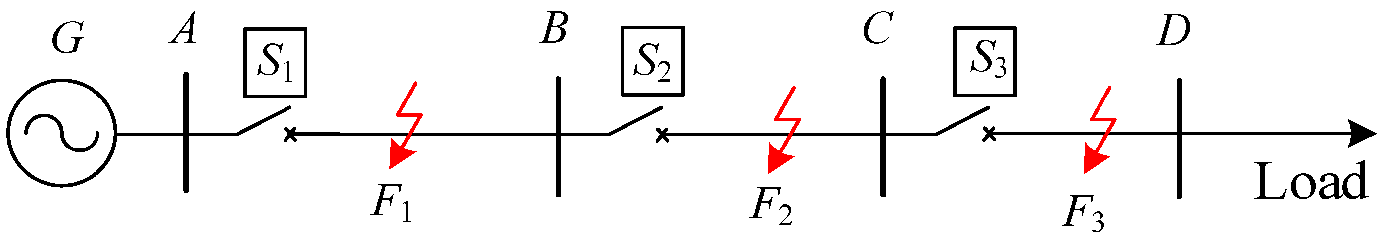
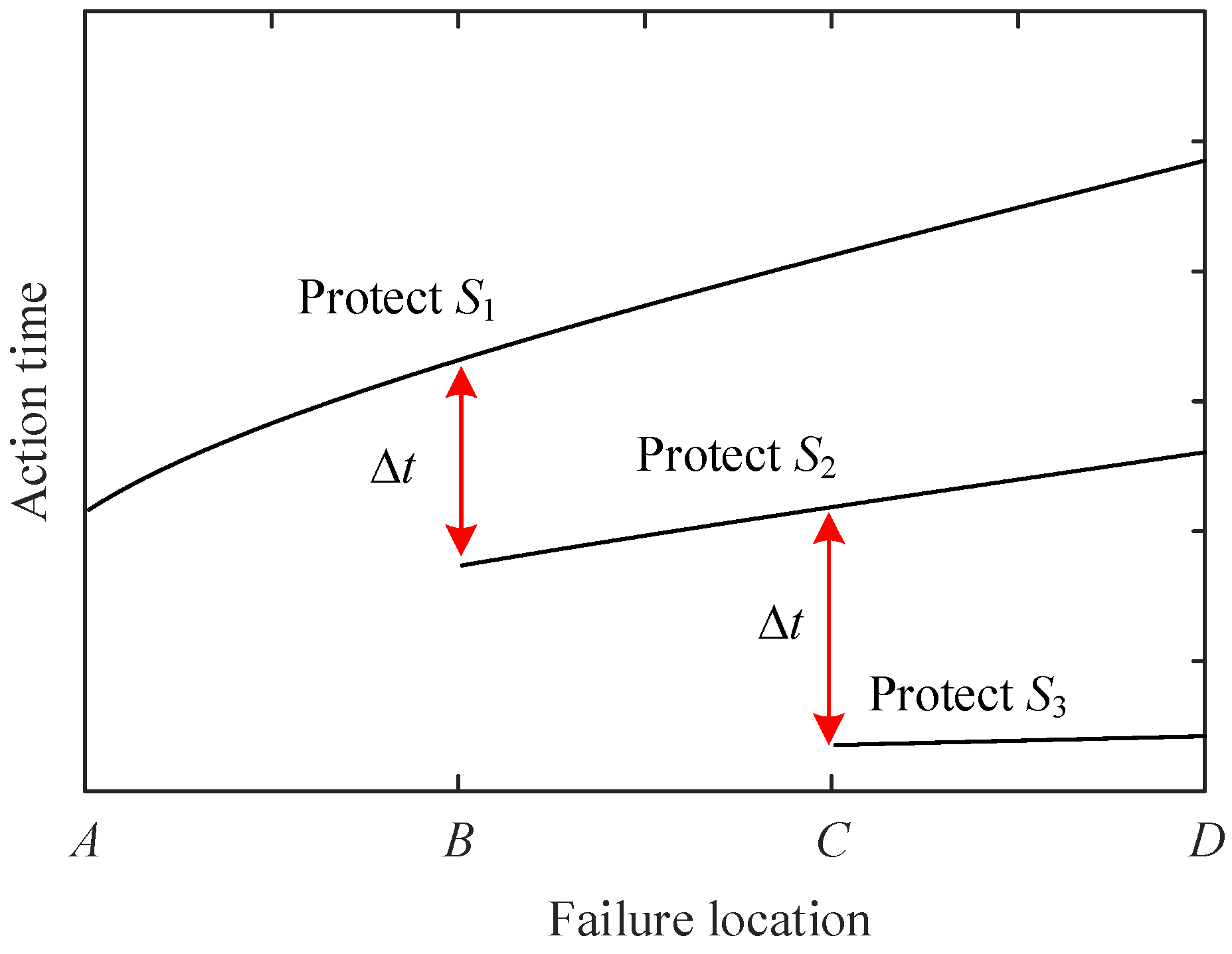
3]. In addition, according to the rectification principle of stage-type current protection, the action rectification time of the backup protection on the power side increases with the number of grid levels [4,5]. It may not exclude serious faults near the power supply side when the main protection is abnormal [6]. In this context, inverse-time over-current (ITOC) protection as an improved scheme of stage-type current protection has received much attention from domestic and foreign experts. Compared with stage-type current protection, the action time of ITOC protection is inversely proportional to the magnitude of short-circuit current, so ITOC protection can quickly remove the fault near the power side. In addition, the change of power system operation mode only changes the action time of ITOC protection, which does not affect its selectivity and sensitivity. In summary, ITOC protection has excellent action performance.
In reference [7], a comprehensive protection scheme based on measured impedance is proposed, including an impedance differential method and an inverse-time low-impedance method, which can clear faults with high sensitivity. Hong et al. [1] proposed an improved ITOC protection method based on the compound fault acceleration coefficient and the beetle antennae search (BAS) optimization method for a microgrid. In [8], an inverse time overcurrent protection setting strategy for a distribution network (DN) based on the improved gray wolf optimizer (GWO) algorithm is proposed. Reference [9] designed a new adaptive protection algorithm for inverse-time over-current relays (OCRs), which can ensure both selectivity and quickness of the relay.
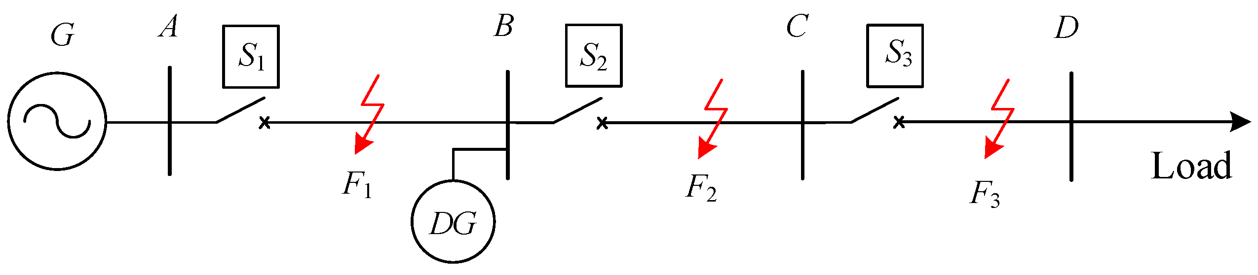
With the rapid development of renewable energy technologies, distributed generation (DG) will be widely used in the power grid [10]. However, with the application of many distributed renewable energy sources, the distribution network has changed from the traditional single-ended power supply to a multi-power pool, and the power supply structure has changed significantly [11,12]. Many researchers have proposed a variety of methods to solve the impact of connecting DG to distribution networks on traditional protection [13]. One part of the research focuses on the protection method depending on the change in electrical information. In [14], an adaptive over-current protection method that diagnosed the microgrid operating mode from the voltage analysis is proposed. Reference [15] proposed a new time-current-voltage tripping characteristic for directional overcurrent relays that can achieve a higher possible reduction of overall relays operating time in meshed distribution networks. In the literature [16], a differential protection method using a non-nominal frequency current during the fault is proposed, which is more sensitive than traditional protection. Amplification of fault characteristics by superposition of positive and negative sequence current after fault is proposed in Reference [17]. With the development of intelligent algorithms, some emphasis on intelligent algorithm protection has been proposed. The authors of [18] proposed an efficient intelligent communication-based protection algorithm that implements different multi-functional protection principles supported by blocking schemes. In [19], the optimization problem of coordination between overcurrent and distance relay is solved by improving the objective function of the genetic algorithm. The authors of [20] proposed an efficient adaptive overcurrent protection and coordination for large-scale wind farms using rule-based fuzzy logic controller (FLC) scheme.
When the DG is connected to the distribution network, the above protection scheme does not have the advantage that when the fault current is higher, the action time is shorter.
In the literature [21], an impedance-accelerated inverse-time over-current (IA- ITOC) protection scheme was proposed. The inverse time characteristic curve is modified by introducing the measured impedance percentage and impedance correction index to improve the protection action speed. However, the method of impedance coefficient adjustment in the literature [21] is too complicated, and there is a risk of protection mismatch [22].
Based on the current situation of the study, the limitations of traditional ITOC protection applied to multi-source distribution networks are analyzed in this paper. In addition, the rules of the IA-ITOC protection scheme are further analyzed to explore the mechanism of the protection mismatch. On this basis, an improved impedance-accelerated inverse-time over-current (IIA-ITOC) protection is proposed. The new protection is based on the improved genetic algorithm (GA) to optimize the protection parameters. Firstly, by increasing the number of optimization stages of backup protection to improve the action speed of the remote backup protection, and then an improved GA is introduced to improve the action time of the overall protection. The improved GA takes the minimum total action time of protection as the objective function, selectivity and sensitivity as the constraint conditions, and establishes the inverse time protection parameter optimization mathematical model to solve the problem. The simulation verifies the superiority of the proposed scheme.

2. Analysis of the Basic Principle and Limitations of Inverse-Time Over-Current Protection

2.1. Basic Principle of Traditional Inverse-Time Over-Current Protection

Reverse Time Overcurrent Protection Basic Principle of Traditional Inverse-Time Over-Current Protection

ITOC protection can automatically adjust the action time according to the fault current, with excellent action performance. In this section, the basic principle and limitations of traditional ITOC protection are analyzed by taking a single-ended distribution network without DG as an example, as follows:
As shown in Figure 1, assuming that the fault is located in line segments AB, BC, and CD, the action equations of reverse-time over-current protection S1, S2, and S3 are shown in (1).
t i j = 0.14 T p i ( I i j / I op i ) α β
where: tij indicates the time of relay protection action, i denotes the number of the protection device, j indicates the number of the line branch, here the default is 1. Tpi is the time rectification coefficient of the protection device i. Iij suggests the size of the current flowing into the relay protection device; Iopi denotes the starting current of the protection device i, which is numerically more significant than the maximum load current of the branch where it is located. α and β are the shape coefficient and translation coefficient of the curve, generally taken as 0.02 and 1 [23].
In order to ensure the selectivity and reliability of the ITOC protection, the protection configuration is usually performed from the lowest level line. Precisely, the start-up current of protection S3 is first calculated using Equation (2).
I op i = K rel K ss K L i . max K re
where: Krel and Kss represent the reliability coefficient and self-starting coefficient of protection respectively; KLi.max indicates the maximum load current of the line where it is located; Kre denotes the return coefficient of the relay protection device. When the fault occurs at the head of the line CD, the protection has a minimum action time of t3min, which is numerically equivalent to the intrinsic action time of the circuit breaker. Substituting t3min and Iop3 into Equation (1) simultaneously, the time adjustment coefficient Tp3 of the protection S3 can be solved. Then the action time curve of ITOC protection S3 can be obtained.
Next, configure the protection S2 of line BC. When a severe fault occurs at the head of the line CD, the action time difference between line BC and line CD of the inverse time limit overcurrent protection is Δt, and the action time of line BC is higher than the action time of line CD. Combined with the Iop2 calculated in (2), the action time curve of protection S2 can be determined. It should be noted that the selection of Δt should consider the influence of many factors. For example, the tripping and extinguishing times of circuit breakers should be considered; the mitigation effect of Δt on the measurement error of the sensor should be considered.
Finally, the AB line protection configuration is the same as the line BC and is not repeated here. If a higher line exists, the reverse-time protection of the higher line is configured step by step. According to the above protection configuration method, the action time curve of each line ITOC protection can be obtained, as shown in Figure 2.
It can be seen that when a fault occurs at a line endpoint (e.g., bus B or C in Figure 2), the action time difference between the upper and lower levels of line protection is Δt. When the fault moves from the head of the line to the end of the line, the action time difference in the protection is monotonically increasing, which can effectively ensure the selectivity of the protection [21]. However, with the increase in the number of line levels, in order to meet the selectivity of the protection, the upper line protection action time will increase more, making the overall protection action time as long.

2.2. Analysis of the Impact of Distributed Power Supply Access on Inverse-Time Over-Current Protection

To analyze the impact of DG access on ITOC protection, an equivalent model of the distribution network with distributed power is constructed, as shown in Figure 3, where the measured currents of protection S1 and S2 are recorded as I ˙ 1 and I ˙ 2 , respectively. When line AB is faulty, the DG does not affect protection S1. In addition, when a fault occurs on the BC or CD line, the DG will generate a infeed current to protect S2 and S3. In order to clarify the impact of DG on protection S2 and S3, the distribution network model is equivalent to the physical model shown in Figure 4, where XAB is the reactance value of line AB. x0 is the unit reactance of lines BC and CD. XDG and XG denote the grid system and DG system reactance values, respectively. l is the distance of the fault point from bus B. Derive the expressions for I ˙ 1 and I ˙ 2 in the above equivalent circuit as (3) and (4) are shown:
I 1 = ( X DG + x 0 l ) U G x 0 l U DG ( X G + X A B ) X DG + ( X G + X A B + X DG ) x 0 l
I 2 = X DG U G + ( X G + X A B ) U DG ( X G + X A B ) X DG + ( X G + X A B + X DG ) x 0 l
It can be seen that both I ˙ 1 and I ˙ 2 are functions with l as the variable. The derivative of l is then derived separately to obtain the rate of change of the protective device current with the fault location, as shown in (5) and (6).
d I 1 d l = ( X D G U G + X G U D G + X A B U D G ) X D G x 0 [ ( X G + X A B ) + ( X G + X A B + X D G ) x 0 l ] 2
d I 2 d l = ( X G + X A B + X D G ) [ X D G U G + ( X G + X A B ) U D G ] x 0 [ ( X G + X A B ) + ( X G + X A B + X D G ) x 0 l ] 2
From (5) and (6), d I 1 / d l < 0 , d I 2 / d l < 0 , with the increase of l, I ˙ 1 and I ˙ 2 are reduced, and the action time of protection S1 and S2 are increased. d I / d l as a function of l is shown in Figure 5. As | d I 2 / d l | > | d I 1 / d l | , the descending speed of I ˙ 2 is greater than that of I ˙ 1 , so the action time of S2 grows faster than that of S1. This causes the action time difference between S1 and S2 being smaller than Δt, as shown in Figure 6. The upper and lower levels of protection may lose their cooperation, and the selectivity of S1 and S2 cannot be satisfied.
In summary, with the gradual increase in distributed power sources in the distribution network, the speed and selectivity of traditional ITOC protection have difficultly in meeting the current needs of the grid. In this context, it is necessary to propose a new protection method, which is suitable for distributed power supply access and has inverse time limit protection characteristics.

3. Inverse-Time Over-Current Protection Based on Impedance Acceleration

A reverse time overcurrent protection scheme based on impedance acceleration was proposed in reference [21]. This scheme mainly solves the problem of poor speed and selectivity of traditional ITOC protection, when the DG is connected to the distribution network. In this section, the principle and limitations of this scheme are discussed.

3.1. Basic Principle of Impedance-Accelerated Inverse-Time Over-Current Protection Theory

Different from traditional ITOC protection, IA-ITOC protection introduces an impedance correction coefficient [21]. The function equation is designed as shown in (7):
t i = 0.14 T p i Z ( I i / I op . i ) n a
where Z indicates the impedance correction coefficient used to correct the protection action time after the DG is connected to the distribution system, and its calculation formula is shown in (8):
Z = { ( Z m / Z all ) r 1 , Z m / Z line < 1 ( Z m / Z all ) r 2 , Z m / Z line 1
where: Zm indicates the measured impedance at the protection installation; Zall suggests the sum of impedance values at the protection installation and down all lines. ri (i = 1, 2) denotes the impedance correction index, r1 and r2 are impedance correction indices where the fault occurs within and outside the action zone.

3.2. Analysis of the Limitations of Impedance-Accelerated Inverse-Time Over-Current Protection

3.2.1. Mismatch of Upper and Lower Level Protection

The action time difference between the upper and lower levels of line protection is Δt. According to the analysis at the end of Section 2.1, Δt is positively correlated with the distance between the fault point and the head of the line at this level. The greater the distance, the greater the Δt. For example, in Figure 2, when the fault occurs between lines BC, Δt between S1 and S2 increases with the distance of the fault point from bus B. Therefore, if the head of the line at this level meets the requirements of selectivity for Δt, then any point of the line at this level meets the requirements of selectivity for Δt. However, for IA-ITOC protection, due to the introduction of the impedance correction coefficient, there may be no linear relationship between the action time difference in the upper and lower protection and the change of fault location. The analysis: different impedance correction coefficients on the impedance-accelerated inverse-time over-current protection action time curves are shown in Figure 7.
As shown in Figure 7, the change in the impedance correction coefficient will significantly affect the action time curve trend of IA-ITOC protection. In this context, if the traditional rectification method is still used, i.e., only to meet the selectivity of the protection when the line endpoint fault, the risk of protection mismatch may occur, as shown in Figure 8. In the figure, the black dotted line and the red solid line are the action time curves of protection S1 and protection S2, respectively.
As shown in Figure 8, due to the introduction of the impedance correction coefficient, the arc of the upper line protection action time curve and the arc of the lower line protection action curve is not consistent. However, the selectivity of protection can meet the requirements when faults occur at both ends of the line, but the protection mismatch occurs when faults occur in the middle of the line.

3.2.2. The Action Time of the Remote Backup Protection Is Too Long

Due to the complexity of IA-ITOC protection setting, this scheme only considers the optimization of the setting value of two-stage backup protection. The action time of the far backup protection of the upper line is still long. The impedance correction coefficient changes the arc of the protection action curve. This may lead to the action time of the remote backup protection being much longer than the traditional ITOC protection scheme, as shown in the red dashed line in Figure 9.
In summary, IA-ITOC protection improves the operation speed of the protection to a certain extent. However, the traditional ITOC protection scheme, which only considers the line endpoint fault, is no longer applicable due to the change of action curve radian. If a suitable optimization algorithm is used for the calibration of this scheme, and a multi-stage backup protection impedance optimization coefficient is introduced, it is expected further to improve the overall operation speed of the protection while satisfying the protection selectivity.

4. A New Inverse-Time Over-Current Protection Optimization Scheme Based on Improved Genetic Algorithm

4.1. New Impedance-Accelerated Inverse-Time Over-Current Protection Scheme

Due to the poor speed of the remote backup protection in IA-ITOC protection scheme, this paper introduces the optimized level of backup protection into the action equation of the security, as shown in (9):
t i = 0.14 T p . i Z r i k ( I i / I op . i ) n a
where, Z = Z m / Z all , k denotes that the current protection is in the backup level, k = 1 indicates the main protection of this level, k = 2 indicates the near backup, and so on. rik indicates the impedance correction index of the current security. Increasing the number of backup protection optimization levels can effectively improve the action speed of the upper-line protection as remote backup protection.
Due to the introduction of backup protection optimization stages, the parameter adjustment becomes more and more complicated, so a new impedance modified inverse time overcurrent protection optimization scheme based on an improved genetic algorithm is proposed: the backup optimization stages are introduced based on the traditional inverse time overcurrent protection, and the adjustment parameters rik, Iopi and Tp.i are optimized by the improved genetic algorithm to improve The selectivity and rapidity of the security are improved.

4.2. Optimization Model Analysis

This optimization model contains optimization objectives and constraints to improve the speed and selectivity of protection.

4.2.1. Optimization Target

From the aspect of enhancing the quick action of protection, the sum of all lines’ main protection and backup protection action time is minimized as the optimization objective. The total optimization objective is established as follows:
min T a l l = i = 1 M j = 1 N k = 1 L ( t p i j + t b i k )
where Tall, M, N, L, tpij, tbik are: the sum of all line main protection and backup protection action time, the number of faulty lines, the number of principal protection, and the number of the backup guards. j and k represent the operation time of the main protection and backup protection when line i is faulty.

4.2.2. Restrictions

The above optimization objectives ensure the speed of ITOC protection and set constraints to ensure the protection selectivity; the primary rules are as follows:
  • Between main and backup protection;
t b i k t p i j C T I
The CTI is the sum of the calculation time of the protection device and the action time of the circuit breaker.
2.
Industry-standard constraints;
The value ranges of some parameters in the action equation of ITOC protection are as follows:
T p min T p i T p max
I p min I p i I p max
r p min r p i r p max
Among them, Tp min, Ip min, ri min, Tp max, Ip max, and ri max are the lower limits of the values of time adjustment coefficient, starting current, and impedance correction coefficient, and the upper limits of the importance of time adjustment coefficient, starting current, and impedance correction coefficient, respectively. Compared with backup protection, which focuses more on the selectivity of protection, main protection prioritizes the speed of protection.
3.
Starting current
It should be noted that: when under the maximum load current, the protection should not be false, and when under the minimum fault current, the defense should act quickly, so the protection starts current other constraints are as follows:
k 1 I L i max I p i k 2 I k i min
where, ILi max, Iki min, k1, and k2 are the maximum load current of line i, the minimum fault current of line i, the corresponding reliability factor, and the sensitivity factor, respectively.

4.3. Improved Quantum Genetic Algorithm

For the above optimization models, intelligent optimization algorithms represented by genetic algorithms are generally used to solve them. However, traditional intelligent algorithms have many problems, such as small sample space, limited search capability, and quickly falling into local optimal solutions, which have substantial limitations in practical use. The improved genetic algorithm is selected as the optimal search algorithm in this paper to solve the above problems [24,25]. The improved genetic algorithm is based on the original genetic algorithm to improve the four aspects of the coding method, population initialization, quantum revolving gate, and quantum variation [26].

4.3.1. Probabilistic Amplitude Based Coding Method

Since the conventional quantum genetic algorithm with chance measurement operations requires constant and frequent encoding and decoding; encoding with probability amplitude reduces the required gene bits per chromosome. Thus, it can improve the algorithm’s convergence in the following form:
P = [ cos t 1 cos t 2     cos t n sin t 1 sin t 2     sin t n ] t i [ 0 , 2 π ]

4.3.2. Population Initialization for Small Habitat Evolutionary Strategies

Given the inefficiency and limited search capability of the traditional intelligent algorithm, the small habitat evolution strategy is introduced to make the distribution of the initial population in the solution space more reasonable, where the jth group of chromosomes is:
q j = [ α 1 β 1 | α 2 β 2 | | α m β m ]
[ α i β i ] = [ j n 1 j n ]
where, n is the number of populations, i = 1 , 2 , m . This initialization method effectively prevents the population from clustering in a particular region, and simultaneous search in multiple directions ensures population diversity and improves the algorithm’s convergence speed.

4.3.3. Quantum Gate Tuning based on Variational Rotating Gates and Adaptive Rotation Angles

In the quantum genetic algorithm, the population is updated with individuals mainly using quantum rotating gates, and the matrix is represented as:
U ( θ i ) = [ cos ( θ i ) sin ( θ i ) sin ( θ i ) cos ( θ i ) ]
[ α i β i ] = U ( θ i ) [ α i β i ]
where U ( θ i ) is a conventional quantum rotational gate; θ i is the rotation angle of the i quantum pair.
The traditional method using a fixed rotation angle without changing the chromosome gene values has a fast convergence rate. Still, it tends to make the population fall into a local optimum. Therefore, the variational rotation gate A and adaptive rotation angle B are introduced here, as Equation:
J = f
K = f f min
n = K / C
K = n ( 1 + m ) ,   0 m 1
Δ θ = { a , f f max { b , a e ( f J ) 2 2 K 2 } , f f
θ = τ ( α , β ) Δ θ
[ α i β i ] = U ( θ ) [ α i β i ] = { [ γ 1 γ ] , α i < γ [ 1 γ γ ] , β i < γ [ α i β i ] , o t h e r w i s e
where, C, a, b, f , fmin, m, τ ( α , β ) , γ are the control parameter (with a value of 2), the maximum (with a weight of 0.05) and minimum (with a value of 0.005) values of the rotation angle of the quantum revolving gate, the average value of the fitness of all individuals in the population, the minimum value of the fitness of all individuals in the population (the importance of the best fitness of the population), the random number, the direction of rotation of the rotation angle, and the constant (with a value of 0.01).
Due to the introduction of U ( θ ) , the upper and lower bounds of the probability amplitude change and converge to γ or 1 γ , preventing falling into local optimal solutions and maintaining population diversity.

4.3.4. Quantum Variation Based on Hadamard Matrix

Since the operation rotation angle π / 2 2 θ of the conventional variation is too large, it is straightforward to produce the loss of information of the optimal individuals. Therefore, when the population is close to the optimal value, the Hadamard matrix is introduced, and the variation operation is performed on the gene positions. The operation rotation angle is shortened to a small size π / 4 2 θ . The expression is as follows:
p = 1 2 [ 1 1 1 1 ] × [ cos θ sin θ ] = [ cos ( π 4 θ ) sin ( π 4 θ ) ] = [ cos ( θ + π 4 2 θ ) sin ( θ + π 4 2 θ ) ]

4.4. Specific Implementation Steps

Considering the above optimization model and algorithm, an impedance-accelerated inverse-time over-current protection optimization adjustment method based on an improved genetic algorithm is proposed, and the appropriate steps are shown below:
Step 1: Initialize the parameters rik, Iopi, and Tp to be optimized using a small habitat evolution strategy while ensuring the relevant constraints;
Step 2: Set different fault locations and different fault types, and calculate the magnitude of the measured current of each protection under different fault scenarios. The resulting current is input into the action equation of IIA-ITOC protection. Then calculate the total action time Tall of corresponding protection under various scenarios;
Step 3: Implement evolutionary updates using quantum gate adjustments based on variational rotational gates, adaptive rotation angles, and variational adjustments based on Hadamard matrices to obtain new optimization parameters. Meanwhile, repeat step 2 to obtain the new total action time;
Step 4: Comparing Tall with T a l l , if T a l l > T a l l , the optimized parameter of the new generation is selected as the current optimal adjustment parameter; if T a l l < T a l l , the original, optimized parameter is retained as the present optimal adjustment parameter;
Step 5: Determine whether the termination condition is triggered; if not, go back to step 3 until the termination condition is activated; if the termination condition is activated, the current optimal rectification parameter is output.

5. Simulation Verification

To verify the reliability and superiority of the proposed optimization method, the simulation model shown in Figure 3 is built in the PSCAD 4.5 software, where the capacity of the load is 0.8 + j0.5 MVA, and the cable length is 10 km. The values of the electromotive force of the system EG and the electromotive force of the distributed power supply EDG are both 10.5 kV. The impedance of the cable per unit length Zl, the internal impedance of the power supply Zs, and the internal impedance of the distributed power supply Zg are, respectively, 0.22 + j0.239 Ω / km , 0.64 + j0.5 Ω , and 6.2 + j3.7 Ω .
According to the above ITOC protection calibration scheme, the traditional inverse time protection of the system connected to DG was calibrated, respectively, and the protection calibration parameters were obtained as shown in Table 1.
Based on the currently constructed electrical simulation model and the derived mathematical model, the improved genetic algorithm is applied to optimize the simulation of the rectification parameters. The specific steps are described in Section 4.3.

5.1. Optimization Results Display

In the improved genetic algorithm, the number of iterations and population size were set to 400 and 100, respectively. The related optimization curves and results are shown in Figure 10 and Table 2, respectively.

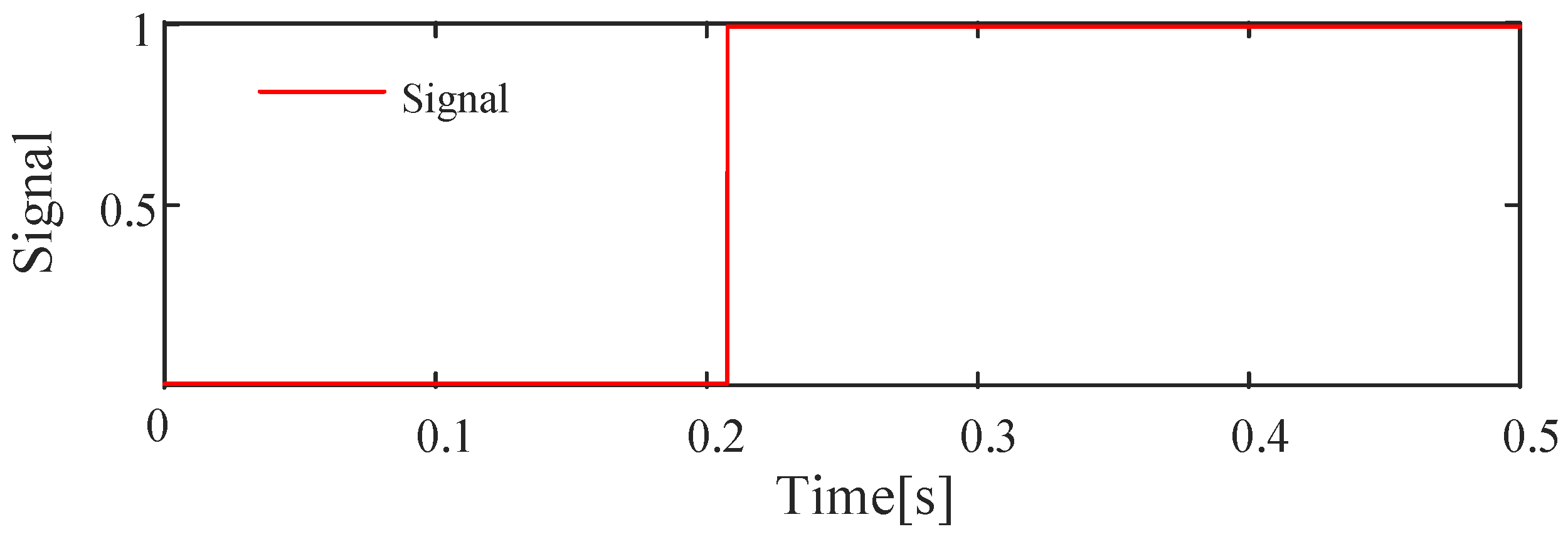
5.2. Simulation Results

Taking the two-phase short circuit fault of line CD as an example, the amplitudes of voltage and current are shown in Figure 11 and Figure 12 respectively, and the fault detection signal is shown in Figure 13.
From Figure 11, Figure 12 and Figure 13, the simulation results can correctly reflect the current, voltage, and detection signals. The simulation model is correct.

5.3. Superiority Analysis

The optimized setting parameters are introduced into the action equation of IIA-ITOC protection and simulated by PSCAD. Then, based on the simulation results, the time of each protection action under different fault locations and fault types is calculated. The calculation results of the proposed protection scheme are compared with those of traditional inverse-time over-current protection and impedance-modified inverse-time over-current protection to verify the advantages of the proposed protection scheme.
Three-phase short circuit fault, two-phase short circuit fault and single-phase ground short circuit fault occur in line AB, BC, and CD, respectively. Various fault types are grounded through different grounding resistors. The action time of traditional ITOC protection, IA-ITOC protection, and IIA-ITOC protection for the above faults are calculated respectively. The results of action time are shown in Table 3, Table 4, Table 5, Table 6, Table 7, Table 8, Table 9, Table 10 and Table 11.

5.3.1. Line CD Fault

Main protection, near backup protection, and remote backup protection of line CD are S3, S2 and S1, respectively. As can be seen from Table 3, when a three-phase ground fault occurs at the line CD, for the remote backup protection S1, the traditional scheme of action time is 0.538 s, and impedance correction scheme of action time is 0.511 s. The action time of the improved scheme proposed in this paper is 0.463 s; compared to the above scheme, its action time is shortened by 75 ms and 48 ms, respectively.

5.3.2. Line BC Fault

The main protection and near backup protection of line BC are S1 and S2, respectively. It can be seen from Table 7 that when line BC has a two-phase grounding short circuit fault with a grounding resistance of 50 Ω, for the main protection S2, the action time of the traditional scheme is 1.54 s, the action time of the impedance correction protection scheme is 1.36 s, and the action time of the improved scheme is approximately 0 s. Compared with the traditional protection scheme and the impedance correction protection scheme, the action time of the improved scheme is shortened by 0.18 s and 1.36 s, respectively.

5.3.3. Line AB Fault

It can be seen from Table 11 that when line AB has a single-phase grounding fault with a grounding resistance of 100 Ω, for the main protection S1, the action time of the traditional scheme is 7.144 s, and the action time of the impedance correction protection scheme is 0.882 s. The action time of the improved scheme proposed in this paper is approximately 0 s, which is significantly improved compared with the above scheme.

5.3.4. Superiority Analysist

(1)
Ground Resistance Effect
From Table 4 and Table 5, it can be seen that when a fault occurs via ground resistance, the near backup protection S2 of line CD have the same action time as the improved scheme and the impedance correction protection scheme. According to Table 7 and Table 8, the action time of the near backup protection S1 of line BC is less than the impedance correction protection scheme. Therefore, the use of the improved scheme as a near-backup protection has a better performance of action than the impedance correction scheme when going through different ground resistance faults. From the data in Table 4, Table 5, Table 7, Table 8, Table 10 and Table 11, it can be seen that the action time of the improved scheme is smaller than that of the traditional protection scheme and impedance correction protection scheme, whether as the main protection or remote backup protection. Therefore, the action performance of the improved protection scheme is better than that of the traditional protection scheme and the impedance correction protection scheme when the grounding resistance fault occurs.
(2)
Fault type effect
Take the data in Table 3 and Table 4 as an example to analyze the impact of different fault types on the improved protection scheme. Table 3 shows that when single-phase grounded short-circuit fault, two-phase short-circuit fault, and three-phase short-circuit fault occur without grounding resistance, the action time of the improved protection scheme is shortened compared with the traditional protection scheme and impedance correction protection scheme. It can be seen from Table 4 that when single-phase ground fault, two-phase ground short circuit fault, and three-phase short circuit fault occur respectively through the grounding resistance, the action time of the improved protection scheme is not longer than that of the traditional protection scheme and impedance correction protection scheme. Therefore, when different types of faults occur, the operation performance of the improved scheme is better than that of the traditional protection scheme and impedance correction protection scheme.
(3)
Fault location impact
The data in Table 4, Table 7 and Table 10 are used to analyze the impact of faults in different lines on the improved protection scheme. In the event of a three-phase short-circuit fault on the line, the action time of the improved scheme is less than that of the traditional protection scheme, and no greater than that of the impedance correction protection scheme. The analysis of two-phase short-circuit grounding and single-phase short-circuit grounding is the same as that of the three-phase short-circuit. Therefore, when faults occur on different lines, the operation performance of the improved scheme is better than that of the traditional protection scheme and impedance correction protection scheme.
Based on the above analysis, it can be seen that compared with the traditional ITOC protection and IA-ITOC protection schemes, the proposed IIA-ITOC protection scheme has better action performance under different fault types and fault locations, whether acting as main protection or backup protection. IIA-ITOC protection can effectively improve the protection speed and performance while ensuring selectivity.

6. Conclusions

Aiming at the defects of poor speed and selectivity of ITOC protection after DG is connected to the distribution network, this paper analyzes the influence mechanism of DG on traditional ITOC protection. It explores the principle of conventional IA-ITOC protection and its limitations. A new inverse-time over-current protection rectification scheme based on an improved genetic algorithm is proposed. The specific conclusions are shown as follows:
(1)
The backup optimization level is added to the new protection scheme, so that the main protection and backup protection have independent impedance acceleration coefficients. The independent impedance acceleration coefficient optimizes the action characteristic curve of the protection, so that the main protection and backup protection, especially the remote backup protection, have better speed and selectivity;
(2)
The improved genetic algorithm not only ensures the search speed, but also improves the diversity of the sample solution space. This algorithm makes the results fall easily into the optimal solution and improves the reliability of the optimization results

Author Contributions

Conceptualization, X.Z. and Z.L.; methodology, X.Z.; software, Y.Z.; validation, X.Z., Z.L. and J.H.; formal analysis, X.W.; investigation, J.H.; resources, X.Z.; data curation, Z.L.; writing—original draft preparation, X.Z.; writing—review and editing, X.Z.; visualization, Z.L.; supervision, X.W; project administration, J.H.; funding acquisition, J.H. All authors have read and agreed to the published version of the manuscript.

Funding

This research received no external funding.

Data Availability Statement

Data is contained within the article.

Conflicts of Interest

The authors declare no conflict of interest.

Nomenclature

ITOCinverse-time over-current
DGdistributed generation
IA-ITOCimpedance-accelerated inverse-time over-current
IIA-ITOCimproved impedance-accelerated inverse-time over-current
GAgenetic algorithm
TCSC-FCLthyristor-controlled series capacitor-based fault current limiter

References

  1. Ji, L.; Cao, Z.; Hong, Q.; Chang, X.; Fu, Y.; Shi, J.; Mi, Y.; Li, Z. An improved inverse-time over-current protection method for a microgrid with optimized acceleration and coordination. Energies 2020, 13, 5726. [Google Scholar] [CrossRef]
  2. Bakar, A.H.A.; Ooi, B.; Govindasamy, P.; Tan, C.; Illias, H.A.; Mokhlis, H. Directional overcurrent and earth-fault protections for a biomass microgrid system in Malaysia. Int. J. Electr. Power Energy Syst. 2014, 55, 581–591. [Google Scholar] [CrossRef]
  3. Singh, M.; Vishnuvardhan, T.; Srivani, S.G. Adaptive protection coordination scheme for power networks under penetration of distributed energy resources. IET Gener. Transm. Distrib. 2016, 10, 3919–3929. [Google Scholar] [CrossRef]
  4. Saldarriaga-Zuluaga, S.D.; López-Lezama, J.M.; Muñoz-Galeano, N. An approach for optimal coordination of over-current relays in Microgrids with distributed generation. Electronics 2020, 9, 1740. [Google Scholar] [CrossRef]
  5. Ge, Q.; Xing, J.; Liu, S.; Li, Z. Analysis and research on the sensitivity of current protection based on the planning and design of distribution networks. IET Gener. Transm. Distrib. 2022, 16, 3208–3217. [Google Scholar] [CrossRef]
  6. Li, j.; Zhang, X.; Yao, W. Inverse time differential current protection for microgrid. In Proceedings of the 2022 IEEE 5th International Electrical and Energy Conference, Nangjing, China, 27–29 May 2022; pp. 590–595. [Google Scholar]
  7. Huang, W.; Tai, N.L.; Zheng, X.D. An impedance protection scheme for feeders of active distribution networks. IEEE Trans. Power Deliv. 2014, 29, 1591–1602. [Google Scholar] [CrossRef]
  8. Yang, Y.; Bian, R.E.; Wang, T.W.; Zhang, J. Inverse time overcurrent optimization of distribution network with DG based on improved gray wolf algorithm. In Proceedings of the 2022 International Conference on Energy Storage Technology and Power Systems, Guilin, China, 25–27 February 2022; pp. 237–246. [Google Scholar]
  9. Sung, B.C.; Lee, S.H.; Park, J.W. Adaptive protection algorithm for overcurrent relay in distribution system with DG. J. Electr. Eng. Technol. 2013, 8, 1002–1011. [Google Scholar] [CrossRef] [Green Version]
  10. Badal, F.R.; Das, P.; Sarker, S.K. A survey on control issues in renewable energy integration and microgrid. Prot. Control Mod. Power Syst. 2019, 4, 87–113. [Google Scholar] [CrossRef] [Green Version]
  11. Dagar, A.; Gupta, P.; Niranjan, V. Microgrid protection: A comprehensive review. Renew. Sust. Energ. Rev. 2021, 149, 111401. [Google Scholar] [CrossRef]
  12. Fani, B.; Bisheh, H.; Sadeghkhani, I. Protection coordination scheme for distribution networks with high penetration of photovoltaic generators. IET Gener. Transm. Distrib. 2018, 12, 1802–1814. [Google Scholar] [CrossRef]
  13. Zhang, F.; Mu, L. New protection scheme for internal fault of multi-microgrid. Prot. Control Mod. Power Syst. 2019, 4, 159–170. [Google Scholar] [CrossRef]
  14. Mahat, P.; Chen, Z.; Bakjensen, B. A simple adaptive over-current protection of distribution systems with distributed generation. IEEE Trans. Smart Grid 2011, 2, 428–437. [Google Scholar] [CrossRef]
  15. Saleh, K.A.; Zeineldin, H.H.; Al-Hinai, A.; El-Saadany, E.F. Optimal coordination of directional overcurrent relays using a new time–current–voltage characteristic. IEEE Trans. Power Deliv. 2015, 30, 537–544. [Google Scholar] [CrossRef]
  16. Soleimanisardoo, A.; Karegar, H.K.; Zeineldin, H.H. Differential frequency protection scheme based on off-nominal frequency injections for invPlease do NOT change the reference format with EndNote and other tools. Our production editor has done thoroughly layout work for the reference. If any changes are necessary, please use the “Track changes function”. Thanks for your cooperation.erter-based islanded microgrids. IEEE Trans. Smart Grid 2019, 10, 2107–2114. [Google Scholar]
  17. Muda, H.; Jena, P. Superimposed adaptive sequence current based microgrid protection: A new technique. IEEE Trans. Power Deliv. 2017, 32, 757–767. [Google Scholar] [CrossRef]
  18. Xyngi, I.; Popov, M. An intelligent algorithm for the protection of smart power systems. IEEE Trans. Smart Grid 2013, 4, 1541–1548. [Google Scholar] [CrossRef]
  19. Chabanloo, R.M.; Abyaneh, H.A.; Kamangar, S.S.H.; Razavi, F. Optimal combined overcurrent and distance relays coordination incorporating intelligent overcurrent relays characteristic selection. IEEE Trans. Power Deliv. 2011, 26, 1381–1391. [Google Scholar] [CrossRef]
  20. Rezaei, N.; Uddin, M.N. Fuzzy logic based adaptive overcurrent protection for wind farms. In Proceedings of the 2021 2nd International Conference on Robotics, Electrical and Signal Processing Techniques, Dhaka, Bangladesh, 5–7 January 2021; pp. 768–771. [Google Scholar]
  21. Huang, J.; Zhang, Y.; Li, J. A new in-verse time overcurrent protection scheme based on impedance correction. Power Syst. Prot. Control 2020, 48, 88–94. [Google Scholar]
  22. Chang, C.K.; Elmashtoly, A.M. Protection coordination index assessment using fuzzy logic controller. Energies 2022, 15, 1377. [Google Scholar] [CrossRef]
  23. Stojanovic, Z.N.; Djuric, M.B. Table based algorithm for inverse-time overcurrent relay. Int. J. Electr. Eng. 2014, 65, 213–220. [Google Scholar] [CrossRef] [Green Version]
  24. Javidi, M.; Hosseinpourfard, R. Chaos genetic algorithm instead genetic algorithm. Int. Arab. J. Inf. Technol. 2015, 12, 163–168. [Google Scholar]
  25. Heras, U.L.; Alvarez-Rodriguez, U.; Solano, E.; Sanz, M. Genetic algorithms for digital quantum simulations. Phys. Rev. Lett. 2016, 116, 230504. [Google Scholar] [CrossRef] [PubMed]
  26. Laboudi, Z.; Chikhi, S. Comparison of genetic algorithm and quantum genetic algorithm. Int. Arab. J. Inf. Technol. 2012, 9, 243–249. [Google Scholar]
Figure 1. Typical grid structure.
Energies 16 01119 g001
Figure 2. Dynamic characteristic curve of traditional inverse time limit protection.
Energies 16 01119 g002
Figure 3. Diagram of distribution network with DG.
Energies 16 01119 g003
Figure 4. Equivalent impedance model of distributed power supply after access.
Energies 16 01119 g004
Figure 5. The functional relationship between d I / d l and l.
Energies 16 01119 g005
Figure 6. Schematic diagram of protection mismatch with DG.
Energies 16 01119 g006
Figure 7. Influence of different impedance correction coefficients on the action time curve.
Energies 16 01119 g007
Figure 8. Schematic diagram of protection mismatch.
Energies 16 01119 g008
Figure 9. Action time curve of IA-ITOC protection.
Energies 16 01119 g009
Figure 10. Optimization curve based on quantum genetic algorithm.
Energies 16 01119 g010
Figure 11. Current amplitude of a two-phase short-circuit fault on line CD.
Energies 16 01119 g011
Figure 12. Voltage amplitude of a two-phase short-circuit fault on line CD.
Energies 16 01119 g012
Figure 13. Fault detection signal.
Energies 16 01119 g013
Table 1. Optimal setting parameters of traditional inverse time limit current protection.
Protection DevicesTime Rectification Coefficient TpiStart-Up Current Iop
S10.1510.118 kA
S20.0740.142 kA
S30.0120.142 kA
Table 2. Optimized setting parameters of inverse-time over-current protection.
Protection
Devices
Start-Up Current Iop Time Rectification Coefficient Tp Main Protection Coefficientat This Level r1Near-Backup Protection Coefficient r2Remote-Backup Protection Coefficient r3
S165 A0.191200.6320.709
S288 A0.077200
S388 A0.00520
Table 3. Operating time of different protection schemes in the case of line CD via 0 Ω ground resistance fault.
Fault TypeProtection LocationFault CurrentStart-Up CurrentAction Time
Traditional ProgramsImpedance AccelerationImprovements
Three-phase short circuitS1814 A65 A0.538 s0.511 s0.463 s
S2977 A88 A0.264 s0.224 s0.208 s
S3977 A88 A0.044 s0.011 s0 s
Two-phase short circuitS1725 A65 A0.574 s0.544 s0.452 s
S2871 A88 A0.279 s0.239 s0.218 s
S3871 A88 A0.045 s0.011 s0 s
Single-phase ground short circuitS1169 A68 A2.591 s2.558 s2.490 s
S2203 A90 A1.271 s1.231 s1.231 s
S3203 A90 A1.031 s0.011 s0 s
Table 4. Operating time of different protection schemes in the case of line CD via 50 Ω ground resistance fault.
Fault TypeProtection LocationFault CurrentStart-Up CurrentAction Time
Traditional ProgramsImpedance AccelerationImprovements
Three-phase short circuitS1180 A68 A2.636 s2.609 s2.561 s
S2216 A90 A1.194 s1.154 s1.154 s
S3216 A90 A0.974 s0.941 s0 s
Two-phase short-circuit ground faultS1152 A68 A2.738 s2.708 s2.65 s
S2183 A90 A1.328 s1.288 s1.288 s
S3183 A90 A1.108 s1.074 s0 s
Single-phase ground short circuitS1114 A68 A3.841 s3.808 s3.74 s
S2137 A90 A1.883 s1.843 s1.843 s
S3137 A90 A1.643 s0.623 s0 s
Table 5. Operating time of different protection schemes in the case of line CD via 100 Ω ground resistance fault.
Fault TypeProtection LocationFault CurrentStart-Up CurrentAction Time
Traditional ProgramsImpedance AccelerationImprovements
Three-phase short circuitS1124 A68 A3.532 s3.505 s3.457 s
S2149 A90 A1.731 s1.691 s1.691 s
S3149 A90 A1.511 s1.478 s0 s
Two-phase short-circuit ground faultS1108 A68 A3.853 s3.823 s3.765 s
S2129 A90 A1.884 s1.844 s1.844 s
S3129 A90 A1.65 s1.616 s0 s
Single-phase ground short circuitS196 A68 A4.561 s4.528 s4.46 s
S2115 A90 A2.244 s2.204 s2.204 s
S3115 A90 A2.004 s0.984 s0 s
Table 6. Operating time of different protection schemes in the case of line BC via 0 Ω ground resistance fault.
Fault TypeProtection LocationFault CurrentStart-Up CurrentAction Time
Traditional ProgramsImpedance AccelerationImprovements
Three-phase short circuitS11231 A68 A0.441 s0.297 s0.290 s
S21479 A90 A0.216 s0.043 s0 s
S30.8 A90 A---
Two-phase short circuitS11090 A68 A0.466 s0.313 s0.303 s
S21309 A90 A0.227 s0.047 s0 s
S31.6 A90 A---
Single-phase ground short circuitS1175 A68 A3.102 s2.94 s2.927 s
S2210 A90 A1.521 s1.334 s0 s
S33.1 A90 A
Table 7. Operating time of different protection schemes in the case of line BC via 50 Ω ground resistance fault.
Fault TypeProtection LocationFault CurrentStart-Up CurrentAction Time
Traditional ProgramsImpedance AccelerationImprovements
Three-phase short circuitS1191 A68 A2.842 s2.698 s2.69 s
S2230 A90 A1.389 s1.216 s0 s
S374.0 A90 A
Two-phase short-circuit ground faultS1160 A68 A3.175 s3.022 s3.012 s
S2193 A90 A1.54 s1.36 s0 s
S362.7 A90 A
Single-phase ground short circuitS1117 A68 A4.630 s4.468 s4.455 s
S2140 A90 A2.282 s2.0950 s
S345.4 A90 A
Table 8. Operating time of different protection schemes in the case of line BC via 100 Ω ground resistance fault.
Fault TypeProtection LocationFault CurrentStart-Up CurrentAction Time
Traditional ProgramsImpedance AccelerationImprovements
Three-phase short circuitS1128 A68 A4.241 s4.097 s4.09 s
S2154 A90 A2.074 s1.901 s0 s
S376.2 A90 A
Two-phase short-circuit ground faultS1110 A68 A4.617 s4.464 s4.454 s
S2132 A90 A2.251 s2.071 s0 s
S365.8 A90 A
Single-phase ground short circuitS197.5 A68 A5.567 s5.405 s5.392 s
S2117 A90 A2.73 s2.54 s0 s
S358.0 A90 A
Table 9. Operating time of different protection schemes in the case of line AB via 0 Ω ground resistance fault.
Fault TypeProtection LocationFault CurrentStart-Up CurrentAction Time
Traditional ProgramsImpedance AccelerationImprovements
Three-phase short circuitS12242 A68 A0.35 s0.045 s0 s
S24.8 A90 A
S34.8 A90 A
Two-phase short circuitS11974 A68 A0.365 s0.046 s0 s
S26.6 A90 A
S36.6 A90 A
Single-phase ground short circuitS1185 A68 A3.9 s0.487 s0 s
S25.2 A90 A
S35.2 A90 A
Table 10. Operating time of different protection schemes in the case of line AB via 50 Ω ground resistance fault.
Fault TypeProtection LocationFault CurrentStart-Up CurrentAction Time
Traditional ProgramsImpedance AccelerationImprovements
Three-phase short circuitS1210 A68 A3.736 s0.479 s0 s
S277 A90 A
S377 A90 A
Two-phase short-circuit ground faultS1175 A68 A4.117 s0.515 s0 s
S265 A90 A
S365 A90 A
Single-phase ground short circuitS1122 A68 A5.914 s0.73 s0 s
S245.8 A90 A
S345.8 A90 A
Table 11. Operating time of different protection schemes in the case of line AB via 100 Ω ground resistance fault.
Fault TypeProtection LocationFault CurrentStart-Up CurrentAction Time
Traditional ProgramsImpedance AccelerationImprovements
Three-phase short circuitS1137 A68 A5.728 s0.734 s0 s
S277.6 A90 A
S377.6 A90 A
Two-phase short-circuit ground faultS1116 A68 A6.211 s0.776 s0 s
S266.7 A90 A
S366.7 A90 A
Single-phase ground short circuitS1101 A68 A7.144 s0.882 s0 s
S258.2 A90 A
S358.2 A90 A
Disclaimer/Publisher’s Note: The statements, opinions and data contained in all publications are solely those of the individual author(s) and contributor(s) and not of MDPI and/or the editor(s). MDPI and/or the editor(s) disclaim responsibility for any injury to people or property resulting from any ideas, methods, instructions or products referred to in the content.

