

Comparison of Impact on Turbine Shafts Torsional Behavior for Integration of Two Types of Wind Farm into a Series-Compensated Transmission System

Department of Electrical Engineering, National Taitung Junior College, No. 889, Jhengci N. Road, Taitung City 95045, Taiwan
Energies 2022, 15(18), 6796; https://0-doi-org.brum.beds.ac.uk/10.3390/en15186796
Submission received: 22 August 2022
/
Revised: 12 September 2022
/
Accepted: 14 September 2022
/
Published: 16 September 2022
(This article belongs to the Special Issue Interactions of Electric Grids, Wind and Photovoltaic Power Generation, Energy Storage and Power Generation Forecasting)
Abstract
:Deep decarbonization is the goal of modern power systems, so it is inevitable that large-scale wind farms will be integrated into systems. This also gives rise to many problems, which have been studied in detail in the literature. However, these studies basically have two deficiencies. One is to assume that traditional generator units are fully loaded, and the other is not to compare the differences in the impact of different types of wind farm. This paper discusses these two points in detail. Taking a series-compensated transmission system as the research object, and assuming that the wind farm only replaces part of the power of the traditional generator unit in the transition period of energy conversion, the difference between the torsional vibration behaviors of the traditional unit caused by adopting different types of wind farm is discussed. The results of the study show that the impact of integration of the type 3 wind farm is dominated by the induction generator effect of doubly fed induction generator units. The penetration rate as low as 19% could cause instability. However, the paralleled metal-oxide varistor can effectively improve the stability. For the type 4 wind farm, the dominant factor turns out to be the de-rating operations of the steam turbine generator unit. The allowable penetration rate depends on the turbine damping. When the turbine damping is sufficient, the penetration rate can be as high as 87.5%. In conclusion, in order to integrate wind farms into a series compensated transmission system, one should not only focus on the compensation factor to avoid the sub-synchronous torsional vibrations, but also pay attention to the types of wind farm as well as the penetration rate. The findings can be used as the decision-making basis for the integration of wind farms during the energy transition period.
1. Introduction
Owing to energy depletion and environmental pollution, energy saving and carbon reduction have become primary appeals for all walks of life all over the world. As a result, the utilization of clean and renewable energies has become the mainstream of electric power development. Consequently, plenty of large-scale wind farms are being integrated into the existing power systems to replace the coal-fired generation units. The power system gradually develops toward the wind power high penetration system. However, such a development causes a lot of problems for power systems. When wind farm power is integrated into a power system, in addition to the wind power generator units, a lot of power regulation equipment like static VAR compensators and static synchronous compensators will also be incorporated into the system. Usually, they are equipped with non-linear characteristics, so a lot of harmonics are then introduced into the system. That might disturb the system’s operations [1,2]. The fluctuating nature of wind power makes power generation forecasts more and more difficult. That challenges the unit commitment of power plants and power dispatch of a power system [3,4]. Inadequate reactive power capacity of wind power generator units limits the capability of maintaining the system voltage. That affects the system voltage stability [5]. Lacking adequate inertia for wind power generator units reduces the inertia of the power network. That will affect the system’s transient stability when there is a large disturbance like a short-circuit fault [6]. More than that, when there is a short-circuit fault, the tripping of a wind farm might give rise to a chain reaction and eventually result in a wide range of power loss. That challenges the system protection and coordination, as well as the voltage and frequency ride-through capability of wind power generator units [7,8].
Among the above-mentioned problems, there is no doubt the impact on system stability is a worthwhile consideration. The integration of wind farms can give rise to both small signal dynamic stability problems and large signal transient stability problems for power systems. Several studies have been conducted to investigate the effects of wind penetrations in power networks. The authors of [9] analyzed the dynamic performance of doubly fed induction generator (DFIG) based wind farms and their effect on electromechanical oscillations. It showed that the frequency and damping of the inter-area oscillations would increase with a DFIG-based wind farm on a weak power network. The authors of [10] demonstrated that increasing wind power penetration on the conventional power system can have a significant impact on small-signal power system dynamics and operational characteristics. In refs. [11,12], they show that the high penetration of the DFIG-based wind farm can improve the small signal stability of the power system. In ref. [13], the authors showed that the DFIG-based wind farm could decrease the damping of power oscillations, hence increasing the instability of the power networks. In addition, the wind farm can decrease the damping of the electromechanical oscillations for a DFIG-based wind farm by interacting with the electromechanical modes of the synchronous generator. In ref. [14], the authors showed that the DFIG-based wind farm can change the shapes of local and inter-area modes and result in dynamic instability. For transient stability, there is also a great deal of literature showing that wind generator technologies might influence transient stability [15]. In ref. [16], the authors studied the transient behavior and transient stability evaluation methods for a grid-fed wind turbine generator. The authors of [17] showed that the power network with DFIG-based wind farms could restore power and voltages after a grid fault, thereby enhancing the short-term stability. In addition, the DFIG-based wind turbines can provide some reactive power support during transient disturbances, thereby enhancing the transient response of the power system [18]. Recently, fast expansion of the power electronic equipment and the renewable power plant further challenge the modern power systems. The Sub-Synchronous Torsional Interaction (SSTI) and Sub-Synchronous Control Interaction (SSCI) phenomena have become popular research topics. The SSTI is found to possibly occur between the wind turbine mechanism and the flexible AC transmission system controller, as well as between the steam turbine mechanism and the wind power controller [19]. The SSCI is found to possibly occur between the inverter controls of a wind power generator unit and the series capacitor [20,21].
According to the surveys above, the impacts of integrating wind farms on power system dynamic and transient stability have been extensively studied. However, these studies have two deficiencies. One is to assume that the traditional generator unit is fully loaded. It was rarely studied whether the wind farm could replace part of the power of a traditional generator unit. In fact, in the transition period of energy transfer toward sustainability, this situation exists. Under such a situation, the traditional generator unit will continue to operate in a reduced power mode because the power of the wind farm is not enough to completely replace the traditional unit. Due to the change in the operation conditions, the electromechanical vibration characteristics of the traditional generator unit would be changed. As a result, the effect of integrating a wind farm on the electromechanical vibration behavior of the unit may also be different. The other is that there is no comparison between the impacts of different types of wind farms. Although types 3 and 4 are the most common in modern wind farms, most research studies only one of them. In fact, there is a fundamental difference between the two types of wind farm. For example, the type 3 wind farm adopts the DFIGs and a partial power converter, while the type 4 wind farm adopts the Permanent Magnet Synchronous Generator (PMSG) units and a full power converter. When these two types of wind farms are incorporated into the power system, the impact will most likely be different. Whether the two points above mentioned really have a noteworthy effect or not, as a matter of fact, depends on the power system configuration. Different configurations may have different results. In this paper, the series-compensated transmission system is chosen as the research object. Under the situation that the wind farm only replaces part of the power and the traditional unit operates with de-rated power, the differences in the torsional vibration behavior of the traditional generator unit caused by the use of different types of wind farms are studied and compared. It is found from the results that the impact of integrating the two types of wind farm on the behaviors of turbine shaft torsional responses will be totally different. For the type 3 wind farm, the dominant factor for the torsional behaviors of steam turbine generator units is the Induction Generator Effect (IGE) of the DFIGs. A penetration rate as low as 19% could induce instability. The stability can be improved by the Metal-Oxide Varistor (MOV) but cannot be influenced by the turbine damping. For the type 4 wind farm, the dominant factor is the de-rating operations of steam turbine generators. A penetration rate of up to 87.5% is allowed. The stability is heavily dependent on turbine damping but cannot be improved by the MOV.
There is literature studying the Sub-Synchronous Resonance (SSR) between wind farms and series compensated transmission systems, but most of them are about induction generators alone. In ref. [22], the authors study the potential of SSR in large wind farms based on double-cage induction generators connected to a series-compensated line. It is concluded that IGE-based SSR can potentially occur even at realistic levels of series compensation. This is a preliminary study of the possibilities. In ref. [23], the authors investigated the effect of varying the capacitive compensation level on the performance of a squirrel cage induction generator through small signal modelling. It is shown that the compensation level increase beyond 50% would lead to electromagnetic torque oscillations at turbine shafts. This is a further study on the critical compensation factor. The authors of [24] used a static synchronous compensator to improve the SSR generated by the induction generator-based wind farm and the series compensated transmission system. This is to further propose the improvement method. Compared with the literature, the studies in this paper have at least the following advances:
- The focus of those studies is on the compensation factor. The effect of the penetration rate is investigated further in this paper. It is shown that the wind power penetration rate that causes instability in vibration modes is slightly different under different compensation factors. The relationship between the compensation factor and the penetration rate thus becomes clear;
- Those studies paid attention only to the effect of the integration of wind farms. The focus of this paper is further placed in the transition period of the energy transition, which is different from those studies. Not only will the wind farm be integrated into the system, but also the traditional generator units will continue to operate with a reduced power mode. Therefore, the factors that will cause the sub-synchronous vibrations are not only the induction generator effect but also the de-rating operations of the traditional generator units. In this paper, the comparative study on the influence degree of the two factors has been further conducted, and it is found that the IGE will be dominant;
- The improvement method proposed in those studies is probably to adopt additional active compensators for compensation control. This is obviously uneconomical in terms of cost considerations. In contrast, MOV is the standard equipment of modern series capacitors. Nevertheless, its impact on the SSR generated by the induction generator-based wind farm and the series compensated transmission system has not been studied. This has been done in this paper, and good efficacy was verified;
- PMSGs are generally not discussed in the SSR issues of series compensated transmission systems, so there is no relevant literature to compare. However, in ref. [25], the authors have shown that replacing traditional generator units with the type 4 wind turbine generators will change the damping and frequencies of the system inter-area modes. Since the research is about the situation of PMSGs completely replacing the traditional generators, there is no de-rating operations for the traditional generators, so there will not be an impact on the torsional modes. This paper, focuses on the transition period of the energy transition. The integration of the PMSG wind farm will indirectly cause the traditional unit to operate with reduced power. The impact on turbine torsional modes can thus be found. Therefore, it has extended the wind farm type from DFIG to PMSG, which was usually ignored before. Additionally, a comparative study on the effects of two types of wind farms has been conducted with respect to the special situation of energy transition, which has never been studied before.
2. System Studied
2.1. System Descriptions
A single-machine-to-infinite-bus power system, having a series-compensated transmission line, is being studied. The single line diagram is shown in Figure 1. The nominal frequency is 60 Hz, and the transmission voltage level is 500 kV. The transmission capacity is limited to 800 MW. The steam turbine generator G is an 892 MVA unit. Two wind farms are connected to the system at the 500 kV bus. One is the type 3 wind farm, which is equipped with the DFIG units, and the other is the type 4 wind farm, which is equipped with the PMSG units. Each of the wind farms consists of 140 wind turbines. Each wind turbine has a nominal active power of 5 MW. When simulation studies are conducted, the 140 wind turbines are aggregated into seven DFIG or PMSG models. Each model represents 20 parallel machines and has 100 MW of active power.
2.2. System Model
The DIgSILENT PowerFactory software is adopted for the analysis and simulations. Built-in models are employed to implement the system under study. However, some modifications and settings are required for the steam turbine generators, DFIG and PMSG.
2.2.1. Steam Turbine Generator Model
The synchronous generator is modeled with a detailed six-order model, and the IEEE Type1 automatic voltage regulator is included. Those models are common and will not be repeated here. However, the turbine-and-generator mechanism needs to be included to study the turbine shaft dynamics, hence the multi-mass model is adopted. The turbine-and-generator mechanism of each unit is equipped with a high-pressure turbine (HP), an intermediate pressure turbine (IP), two low-pressure turbines (LPA and LPB), and an exciter (EXC), in addition to the generator rotor (GEN). The lumped mass-damping-spring model employed is shown in Figure 2. The model parameters are listed in Table 1, where the symbols T, J, K, D, and represent torque, inertia, stiffness, damping, and angular velocity, respectively. The subscripts represent the locations. For example, DHP represents damping of turbine HP, and KHP_IP represents stiffness of the shaft between turbines HP and IP. In addition, Te represents the electromagnetic torque which links the mechanical and electrical systems. Based on the mass-damping-spring model, the dynamic equations can be obtained. Taking the turbine IP as an example, the dynamic equation will be
where represents the turbine angle.
2.2.2. DFIG Model
The DFIG with the control scheme employed is shown in Figure 3. The DFIG generator model is a full-built-in model which integrates the induction machine and Rotor-Side Converter (RSC). The grid-side converter and its control are not included because the DC-link dynamics are not of interest [26,27]. The voltage equations in complex notation and the electromagnetic torque formulas as follows describe the behavior.
where u, i, and are voltage, current, and flux, respectively. The subscripts s and r denote stator and rotor, respectively. is the electromagnetic torque; is the pole pair; and are the synchronous speed and the angular speed of the rotor, respectively.
During time domain simulations the converter is controlled through the pulse width modulation factors and , which define the ratio between DC-voltage and the AC-voltage at the slip rings. The DC-voltage is assumed to be constant because the DC-link dynamics are ignored.
where is the nominal rotor voltage.
DFIG and RSC are represented in a rotor reference frame that rotates at generator speed. However, because the RSC controller operates in a stator flux-oriented reference frame rotating at grid synchronous speed, d-q axis rotor voltages (or PWM indices) and currents must be transformed accordingly.
RSC control modifies the stator active and reactive power by regulating the q- and d-axis rotor currents, respectively. The active power reference is obtained from a look-up table representing the maximum power tracking algorithm. In the event of a fault, the over-frequency protection sub-system can change the active power reference. The reactive power reference can be obtained from a voltage or power factor controller.
The crowbar protection is an integral part of the DFIG model in the DIgSILENT PowerFactory. When the crowbar is triggered, the rotor is short-circuited over the crowbar impedance, the RSC is disabled, and therefore, DFIG behaves as a squirrel cage induction generator with an increased resistance.
The wind turbine is modeled as a two-mass model. The large mass corresponds to the wind turbine’s inertia, and the small mass corresponds to the generator’s inertia. The low-speed shaft is modeled by stiffness and damping, while the high-speed shaft is assumed to be stiff. Moreover, a pitch control is included to regulate turbine speed.
2.2.3. PMSG Model
The PMSG with the control scheme employed is shown in Figure 4. According to [26], PMSGs, which are connected through a full-size converter to the grid, can be modeled as static generators, because the behavior of the plant (from the view of the grid side) is determined by the converter. Usually, if the DC-link dynamics are not of interest, the assumption of the DC-link voltage as a fixed value is sufficient to study the behavior of the power system without much distortion. Therefore, when modeling the PMSGs for the purpose of studies in this paper, the generator-side circuit can be neglected as depicted in the figure. The behaviors of PMSGs are dominated by the grid-side converter, which thus needs to be modeled in detail. The grid-side converter controls active and reactive power in a grid voltage-oriented reference frame. Hence, the active power is controlled by the d-component of the converter current, whereas the reactive power is controlled by the q-component of the converter current. A power reduction function is also included in order to modify the grid power reference in case of fault conditions.
3. Preliminary Studies
In order to understand the characteristics of the system, a fundamental investigation of the system under consideration has been conducted. The study assumes that the steam turbine generator unit has a rated power of 800 MW and that none of the wind power generator units are operational.
3.1. Eigen-Analysis
By using the modal analysis function provided by DIgSILENT PowerFactory, the eigen-analysis can be made to obtain the torsional modes of the steam turbine generator unit. The results are listed in Table 2. There are five torsional modes. It can be seen that each of the modes has a positive value for damping ratio. Therefore, all the modes are dynamically stable.
3.2. Sub-Synchronous Resonance
The transmission line has an impedance of 5.6 + j140.07 ohms. By applying the series capacitor with different susceptance values, the different compensation factors can be obtained. The compensation factor could usually range from about 40% to 75%, hence only the three cases are calculated and listed in Table 3. When the compensation factor is at 74%, SSR would be induced. The resonance mode will be mode 4. In the same manner, when the compensation factors are 56% and 41%, respectively, the resonance modes will be mode 3 and mode 2.
3.3. Transient Simulations
Time-domain simulations can be carried out by using the electromagnetic transient simulation function provided by the DIgSILENT PowerFactory. It is assumed that the transmission line is 65% compensated with a capacitor of 0.011 S. The compensation level has been considered to avoid the possible occurrence of SSR. A 3-phase short-circuit fault, with a fault impedance of 350 Ω, is applied at the grid side of a 500 kV bus and cleared after 0.167 s. For the results, it is focused on the shaft torsional vibrations of the steam turbine generator unit.
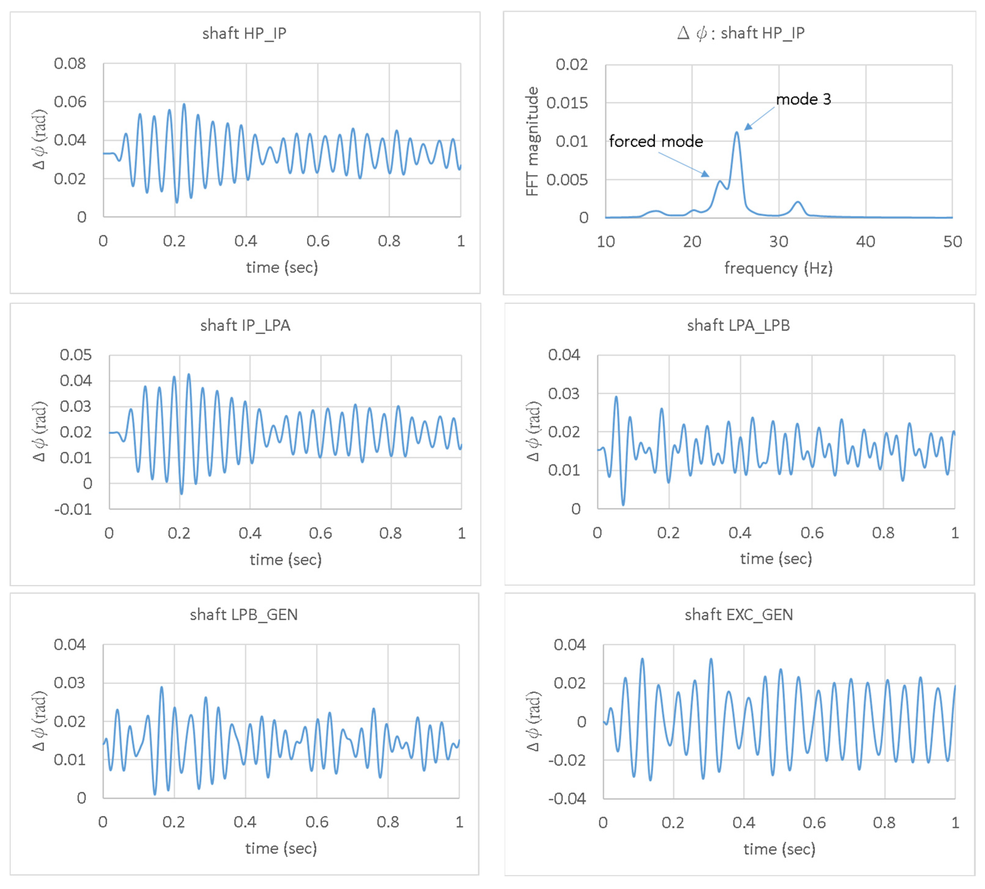
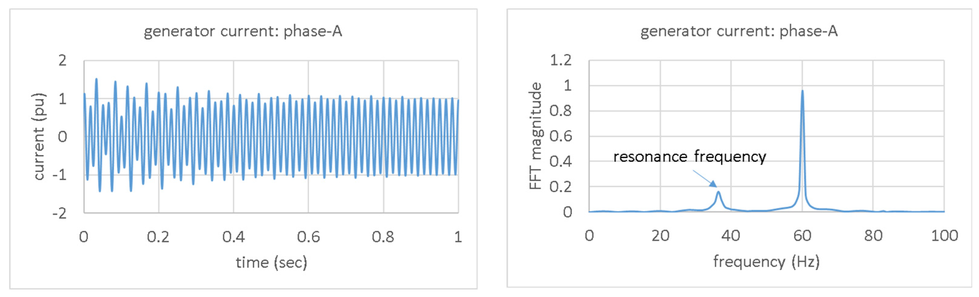
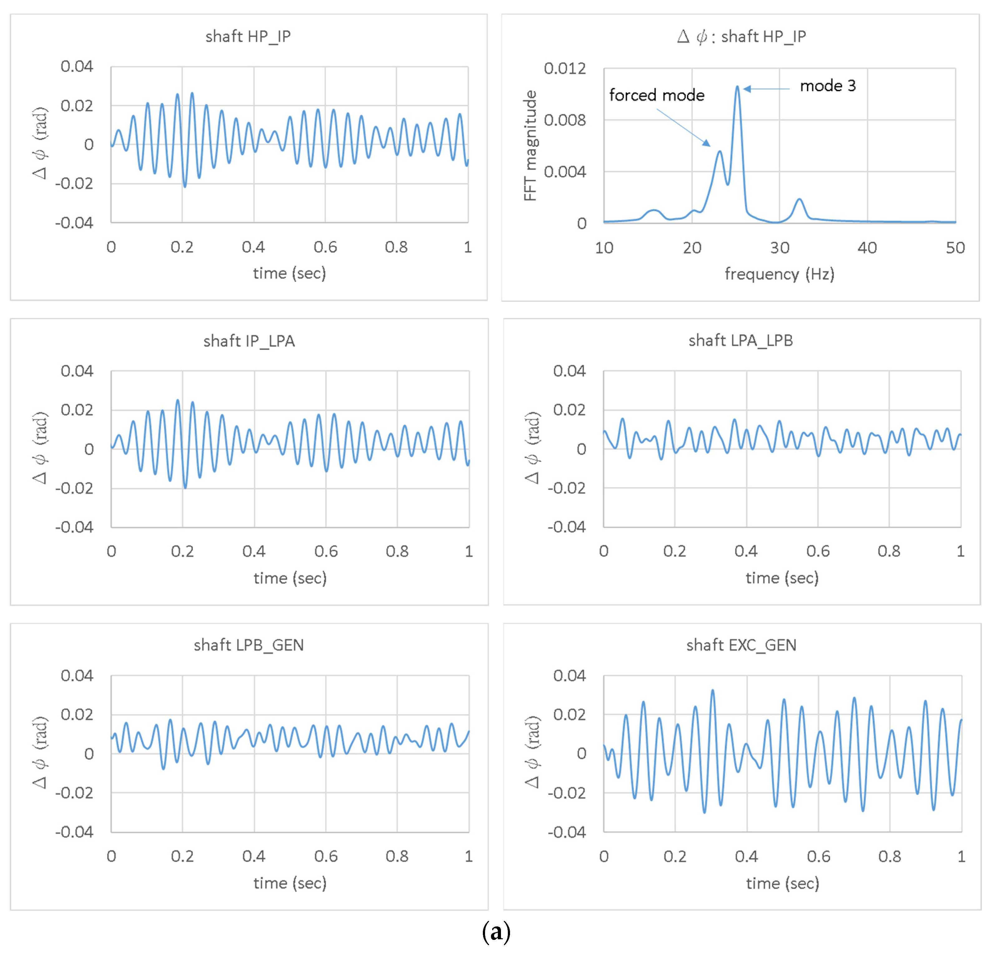
In Figure 5, it shows the resulting shaft torsional angles (), which are equivalent to the torsional vibrations of the generator unit. It can be seen that the responses are convergent. There is no SSR phenomenon, as expected. However, it is noteworthy that the frequency spectrum (obtained by the Fast Fourier Transform (FFT)) of the torsional vibrations at the HP_IP shaft section, as shown in the upper right of the figure, shows that there is a composition of 23 Hz in addition to the inherent torsional modes. This composition is induced by the series compensation, which can be verified by checking the generator current. In Figure 6, the generator phase-A current and its frequency spectrum are shown. It can be seen that, in addition to the 60 Hz composition, there is indeed a 37 Hz composition, which is complementary to 23 Hz. Therefore, the current induced by the series compensation excites non-negligible torsional responses on shafts, though not to such an extent as to give rise to the SSR problems. Hereafter, this mode is called the ‘forced mode’.
4. Integration of a DFIG Wind Farm
Since the transmission line has a limited transmission capacity, the steam turbine generator unit needs to operate with de-rated power when a wind farm is integrated into the system. It is assumed that the DFIG wind power generators are integrated into the system step by step from 100 to 700 MW at an interval of 100 MW. The steam turbine generator therefore operates at a de-rated power ranging from 700 to 100 MW.
4.1. Eigen-Analysis
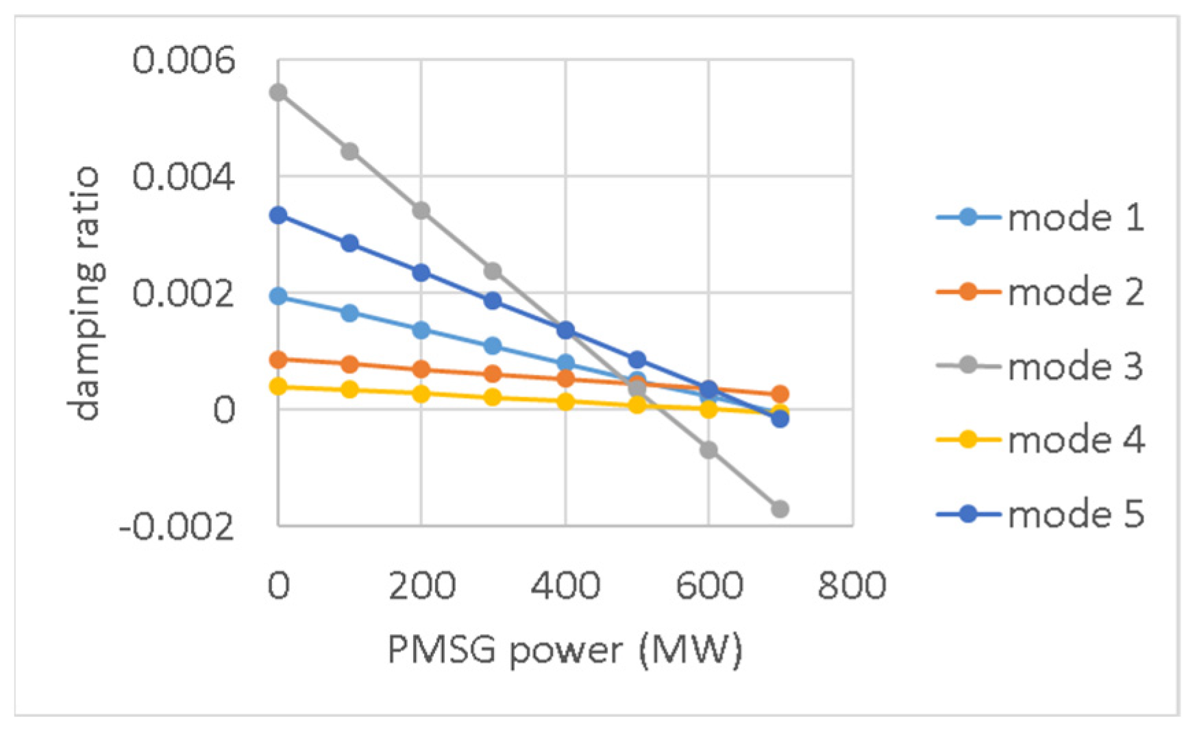
The eigen-analysis is made in each step, and the results are organized. In Figure 7, it shows the damping ratios of torsional modes for various wind powers introduced. It can be seen that the damping ratios of all modes are decreased following the increases in wind power integrated. Obviously, there is negative damping imposed on torsional modes. This negative damping is verified to be caused by the de-rating operations of the synchronous generator by way of self-excitation, because the same results will also be obtained when the generator is operating with de-rated power without any wind farm incorporated. According to the diagram, mode 3 is the most sensitive one to the generator de-rating operations. When the wind power integrated is more than 600 MW (or the steam turbine generator operates with a de-rated power of 200 MW or less), mode 3 will become dynamically unstable. However, this is not important because such an effect will be totally hidden under the IGE of DFIGs as revealed in the following studies.
4.2. Transient Simulations
In the time domain, electromagnetic transient simulations are also made in each step. The events are assumed to be the same as in the preliminary studies. In Figure 8a,b, they show the shaft torsional responses for integration of 100 MW and 200 MW DFIG wind farms, respectively.
The responses are still stable for the condition of 100 MW of wind power. However, according to the frequency spectrum of the shaft HP_IP response as shown in the upper right of the figure, the proportion distribution of compositions has changed. The proportion of mode 3 is decreased, while that of the forced mode is increased. Obviously, the integration of the DFIG wind farm enhances the response of the forced mode.
For the condition of 200 MW wind power, the responses are no longer stable. This is very strange because the compensation factor has been selected to prevent it from inducing the SSR problem, and the eigen-analysis shows all the torsional modes are stable. According to the frequency spectrum of the shaft HP_IP response as shown in the upper right of the figure, it can be seen that it is the forced mode that dominates the vibration behavior instead of mode 3. Since such a sub-synchronous torsional vibration is excited by the resonance current of the compensated line and the vibration frequency does not match with torsional mode frequencies, it is a forced response. The forced response is irrelevant to the torsional modes, so it cannot be analyzed by the eigen-analysis. This leads to the stability revealed by the transient simulation contradicting with that predicted in Section 4.1.
The forced mode is excited by the resonance current of the compensated line. The instability of the forced mode means instability in resonance current. This can be confirmed by Figure 9. In the figure, it shows the generator currents and the torsional responses of the HP_IP shaft for different penetration rates. By cross-checking the currents and torsional responses, it can be seen that they are highly consistent with the inference. Incidentally, it can be seen that the currents suddenly decrease at about 0.9 s and 0.8 s, respectively, for the wind powers of 500 MW (62.5% of penetration rate) and 700 MW (87.5% of penetration rate) situations. The torsional vibrations also reflect such a phenomenon. That is due to the tripping of the wind power generator units because they are equipped with crow bars and protection equipment.
Based on the studies above, the mechanism for inducing the unstable torsional responses can be confirmed as the IGE of DFIGs (refer to Appendix A). Since the resonance frequency of compensated line current is smaller than the system frequency, the slip ratio becomes negative for DFIGs. As a result, the DFIGs provide negative resistance to the current. When integrating 100 MW of wind power (or 20 DFIGs), the negative resistance is still less than the positive resistance, so the resonance current remains stable. When integrating more than 200 MW of wind power (or more than 40 DFIGs), the negative resistance exceeds the positive resistance, so the resonance current gets unstable.
In fact, the IGE and the effect of de-rating operations work simultaneously when the type 3 wind farm is integrated into the system and the traditional generator operates with de-rated power. However, by comparing the results of Section 4.1 and Section 4.2, it can be seen that the effect of IGE is far larger than the effect of de-rating operations. Therefore, the effect of de-rating operations will be hidden under the effect of IGE. Overall, the IGE of DFIGs dominates the torsional response behaviors.
4.2.1. Frequency Shift
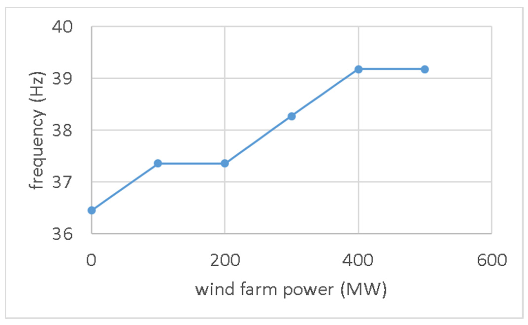
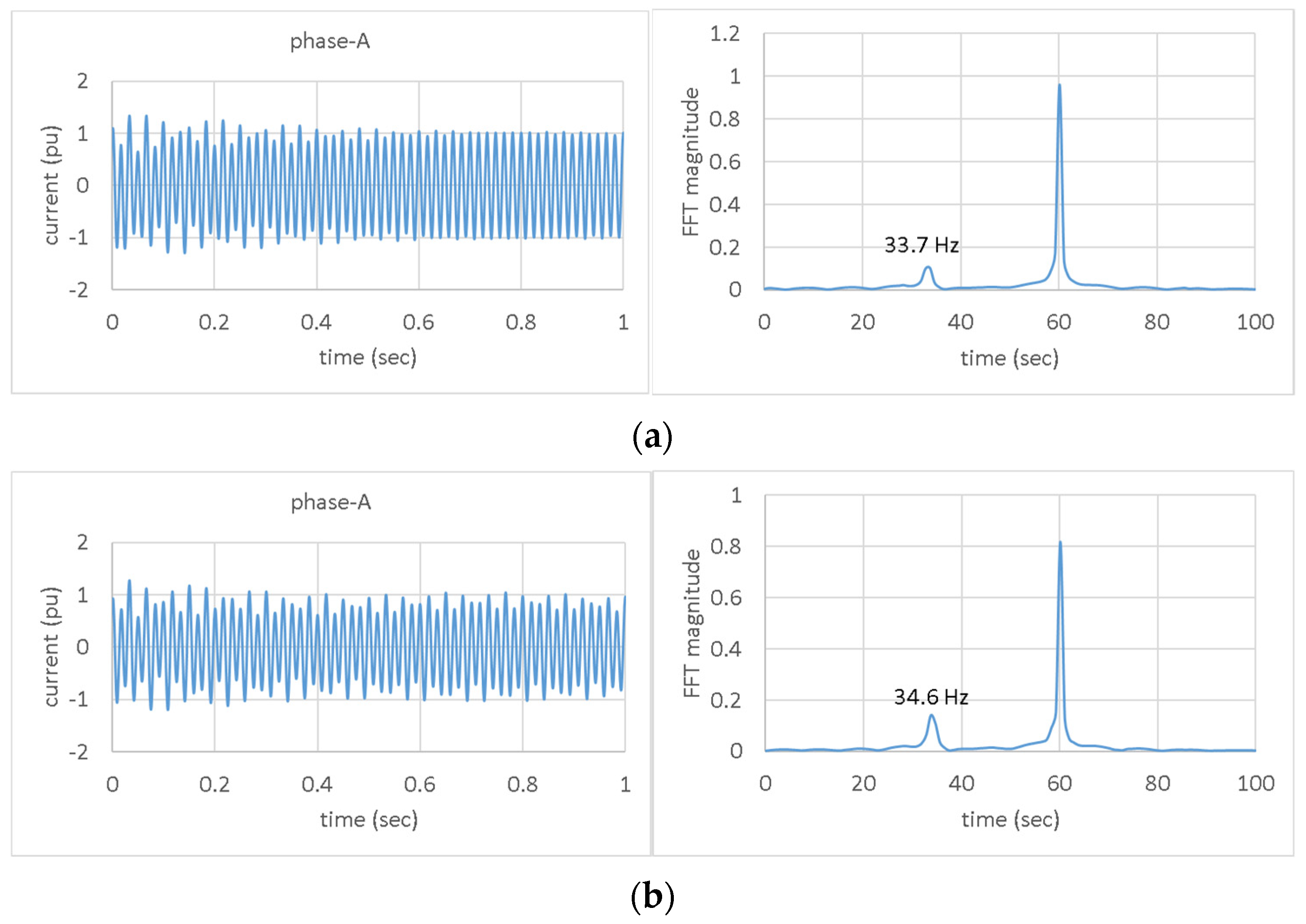
In addition to the effect of IGE, the resonance frequency shift is found to be a significant factor that affects the stability of torsional responses for integration of the DFIG wind farm. Figure 10 shows the resonance frequencies of transmission line current. It is evident that the frequency changes slightly for various penetration rates. Roughly speaking, it is about 1 Hz increase in frequency for every 100 MW increase in wind farm power. For example, the current resonance frequency is 37.4 Hz for integrating 200 MW of wind power. It changes to 39.2 Hz for 400 MW. This is due to the changes in network impedance after the integration of wind power generators. The current resonance frequency increases as the penetrating rate increases. It leads to a decrease in forced mode frequency. Such a frequency shift in forced mode is important and should be paid attention to because it might shift toward or apart from the torsional mode frequency to give rise to or prevent the SSR problem. Take the compensation of Bc = 0.0135 S as an example, for which the transient simulations are done. In Figure 11a,b, the generator currents and their frequency spectrums without and with a 100 MW DFIG wind farm are shown. It can be seen that the resonance currents for both cases are stable. It is inferred from this that the forced mode responses should be stable as well for both cases. However, it does not operate that way, in fact. The real situation is that the current resonance frequency changes from 33.7 to 34.6 Hz for the integration of a 100 MW wind farm. As a result, the frequency of the disturbance to shafts changes from 26.3 to 25.4 Hz. The 25.4 Hz is just the frequency that could interact with mode 3 to induce the SSR. In Figure 12, the torsional responses for the integration of a 100 MW DFIG wind farm are shown. It can be seen that the SSR is indeed induced so that the torsional responses at almost all shafts become unstable.
4.2.2. Studies on Compensation Factor
According to the research, two factors will influence the torsional response of the DFIG wind farm integration. One is the IGE of DFIGs; the other is the frequency shift. So, both the wind power penetration rate and the series compensation factor affect the stability of torsional responses. In Table 4, it confirms the inference. To avoid SSR, the compensation factor of 65%, which is between 74% and 56%, and the compensation factors of 51%, 47%, and 45%, which are between 56% and 41%, are selected for the studies. On the other hand, due to the need for more fine differentiation of the penetration rates, some of the wind turbine generators are not aggregated so that the integrated wind farm power can be adjusted at a step of 5 MW. As a result, the penetration rates of 13%, 16%, 19%, 22%, and 25% as shown in the table can be obtained for the studies. It can be seen that, under different compensation factors, the penetration rate for maintaining stability is slightly different. For 65% of compensation, 19% of the penetration rate is enough to cause instability. For 45% of compensation, it needs a penetration rate of 25% to cause instabilities. Overall, it is recommended for the penetration rate of the DFIG wind farm to be less than 16% to maintain stability, and it will be prohibited for the penetration rate to reach 25% or more. There will be no safety zone for the compensation factor if the penetration rate of the DFIG wind farm exceeds 25%.
5. Integration of a PMSG Wind Farm
In this section, the type 3 wind farm is replaced by the type 4 one. The PMSG wind power generators are integrated into the system step by step to examine their effect on the stability of torsional responses.
5.1. Eigen-Analysis
The eigen-analysis is performed at each step. All the resulting damping ratios of torsional modes are organized in Figure 13. It can be seen that the damping ratios of torsional modes present the same droop characteristic as in the DFIG wind farm situation. It seems that the negative damping introduced is not highly related to the types of wind power generators. So, it is verified again that it is mainly the generator de-rating operations that induce the negative damping instead of the wind power generators. However, there is still a slight difference between the results of the two types of wind power generators. By comparing Figure 13 with Figure 7, it can be seen that the damping ratios of torsional modes in the PMSG situation droop a bit more rapidly than in the DFIG situation. For easier comparison, the damping ratios of mode 5 are shown in Figure 14. Therefore, the integration of a PMSG wind farm introduces a little bit more negative damping than that of a DFIG wind farm.
5.2. Transient Simulations
The transient simulations are also triggered in each step by the same events as in previous studies. In Figure 15a,b, they show the shaft torsional responses for integrating 400 MW and 600 MW of wind power into the system, respectively.
The responses are stable for the integration of a 400 MW wind farm. According to the frequency spectrum of the shaft HP_IP response as shown in the upper right of the figure, mode 3 dominates the vibration behavior. The forced mode is present but plays just a minor role.
The responses are unstable for the integration of a 600 MW wind farm. According to the frequency spectrum of the shaft HP_IP response as shown in the upper right of the figure, it is still mode 3 that dominates the vibration behavior. This matches with the eigen-analysis that the damping ratio of mode 3 becomes negative when 600 MW of wind power is integrated into the system (or the generator operates with a de-rated power of 200 MW). So, due to the absence of IGE in DFIGs, it turns out to be the effect of generator de-rating operations that dominate the stability of torsional responses. Because the inherent torsional modes dominate the responses, the stability can be analyzed using eigen-analysis. That is different from the situation of integrating the DFIG wind farm.
Furthermore, the effect of wind power penetration rate is being studied. In Figure 16, it shows the torsional responses of the HP_IP shaft under situations of different penetration rates. It can be seen clearly that the responses for integrating wind power of 100 MW and 300 MW are stable. When integrating 500 MW of wind power or more, the responses become unstable. In addition, the greater the integration of wind power (or the higher the penetration rate), the more likely the torsional responses are to be unstable. Therefore, the stability of the shafts’ torsional response significantly relies on the penetration rate of wind power. However, it should be noted that the negative damping causing the instability is, in fact, coming from the generator de-rating operations. Such unstable responses could be excited by a disturbance as long as the generator operates with de-rated power, no matter if there is a series compensation or if there is a PMSG wind farm. Incidentally, the stability revealed by the transient simulation is different from that by the eigen-analysis under the 500 MW wind power situation. That is the difference between large and small signal disturbances.
6. Effect of Turbine Damping
Turbine inherent damping is usually highly relevant to shaft torsional vibrations. So, different damping coefficients are applied to all stages of steam turbines to examine their effects.
6.1. DFIG Wind Farm Situation
The transient simulation is used to evaluate the stability of the DFIG wind farm during integration. The simulation conditions remain unchanged. In Table 5, it shows the results for various damping coefficients of turbine masses and shafts. It can be seen that, no matter how much the turbine damping coefficient is, the shaft torsional vibrations get unstable when the 200 MW wind farm is incorporated. Based on the results, it can be learned that the unstable torsional responses are irrelevant to the turbine damping and thus cannot be improved by the augmentation of turbine damping.
6.2. PMSG Wind Farm Situation
When integrating the PMSG wind farm, the eigen-analysis is used to evaluate the stability for different turbine damping. In Table 6, it lists the cases studied. Case 1 has the largest damping coefficients, while Case 4 has zero damping coefficients. In Table 7, it shows the resulting damping ratios for various cases under different penetration rates. It can be seen that when the turbine damping coefficients are decreased, the penetration rate needs to be decreased as well to ensure stability. For case 1, all the torsional modes are stable, even though the penetration rate is up to 87.5%. For case 4, the penetration rate needs to be lower than 50% to avoid unstable responses. Therefore, turbine damping plays a significant role.
7. Effect of MOV
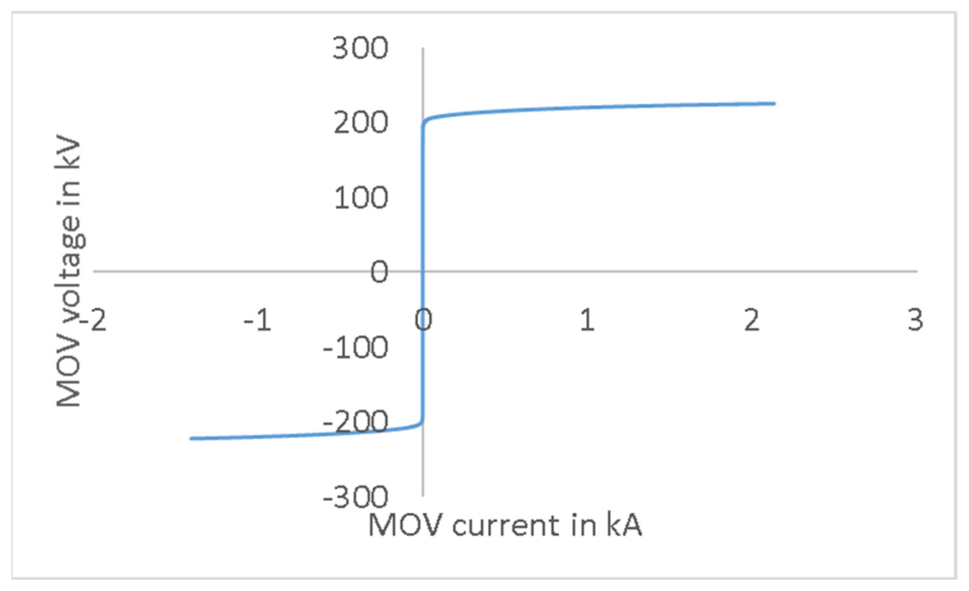
For a modern series compensator, the series capacitor is protected by a parallel MOV. The MOV limits the surge voltage across the capacitor based on its rated protective level. It is studied in this section for its effect on the torsional responses when integrating wind farms into the system. The MOV adopted has the characteristics as shown in Figure 17. The critical voltage is 200 kV. When the voltage across the MOV exceeds the critical voltage, the MOV starts conducting current to maintain the voltage at the critical voltage.
7.1. DFIG Wind Farm Situation
For the integration of a 300 MW DFIG wind farm, the turbine shaft transient responses with MOV are shown in Figure 18. The simulation events are the same as in previous studies except the fault impedance has changed to 11.6 Ω to induce a larger disturbance. It can be seen that the shaft vibrations are still relatively severe. However, they are limited in their range. It is evident that the incorporation of a MOV effectively eliminates the unstable torsional responses on shafts.
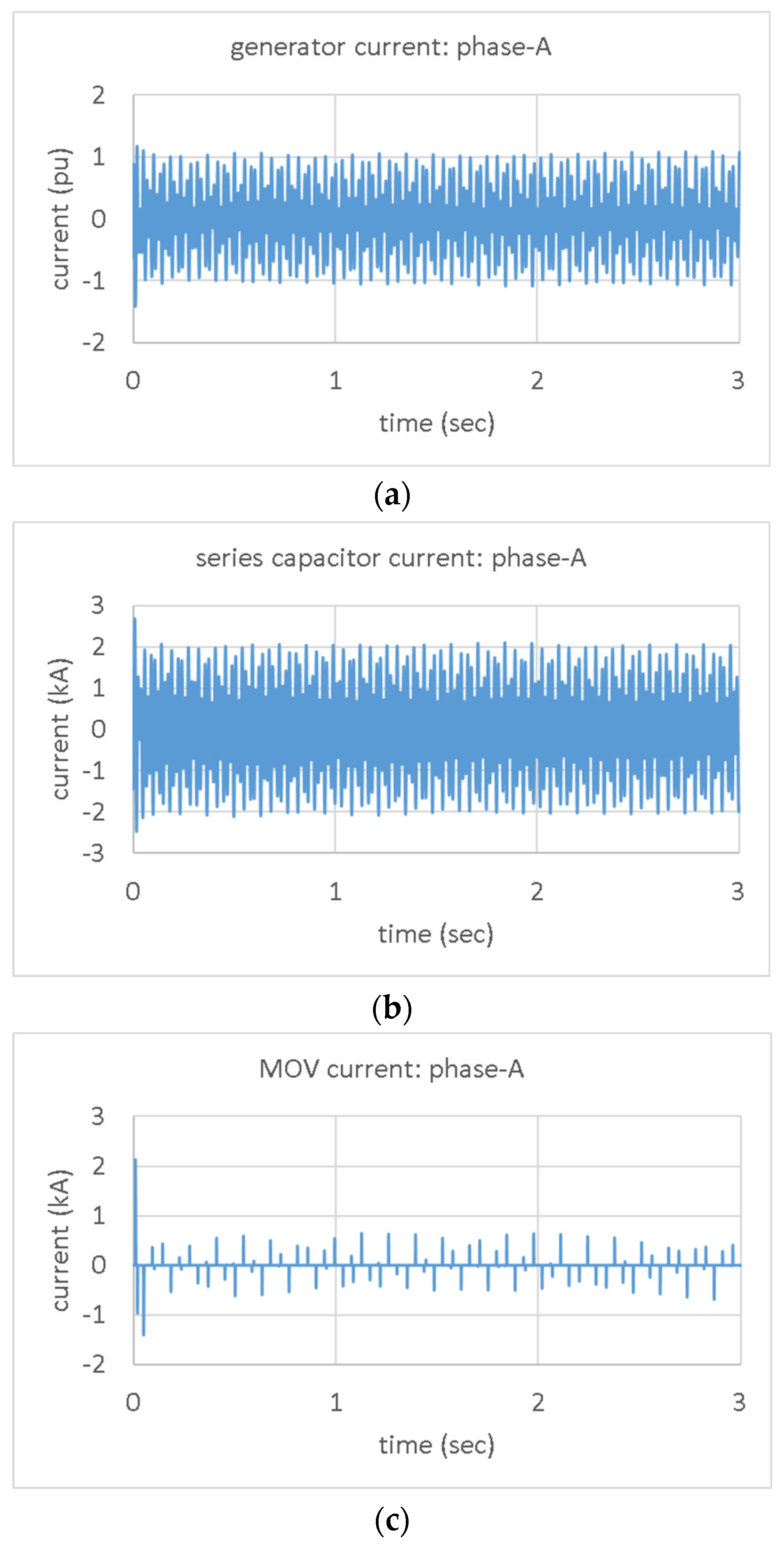
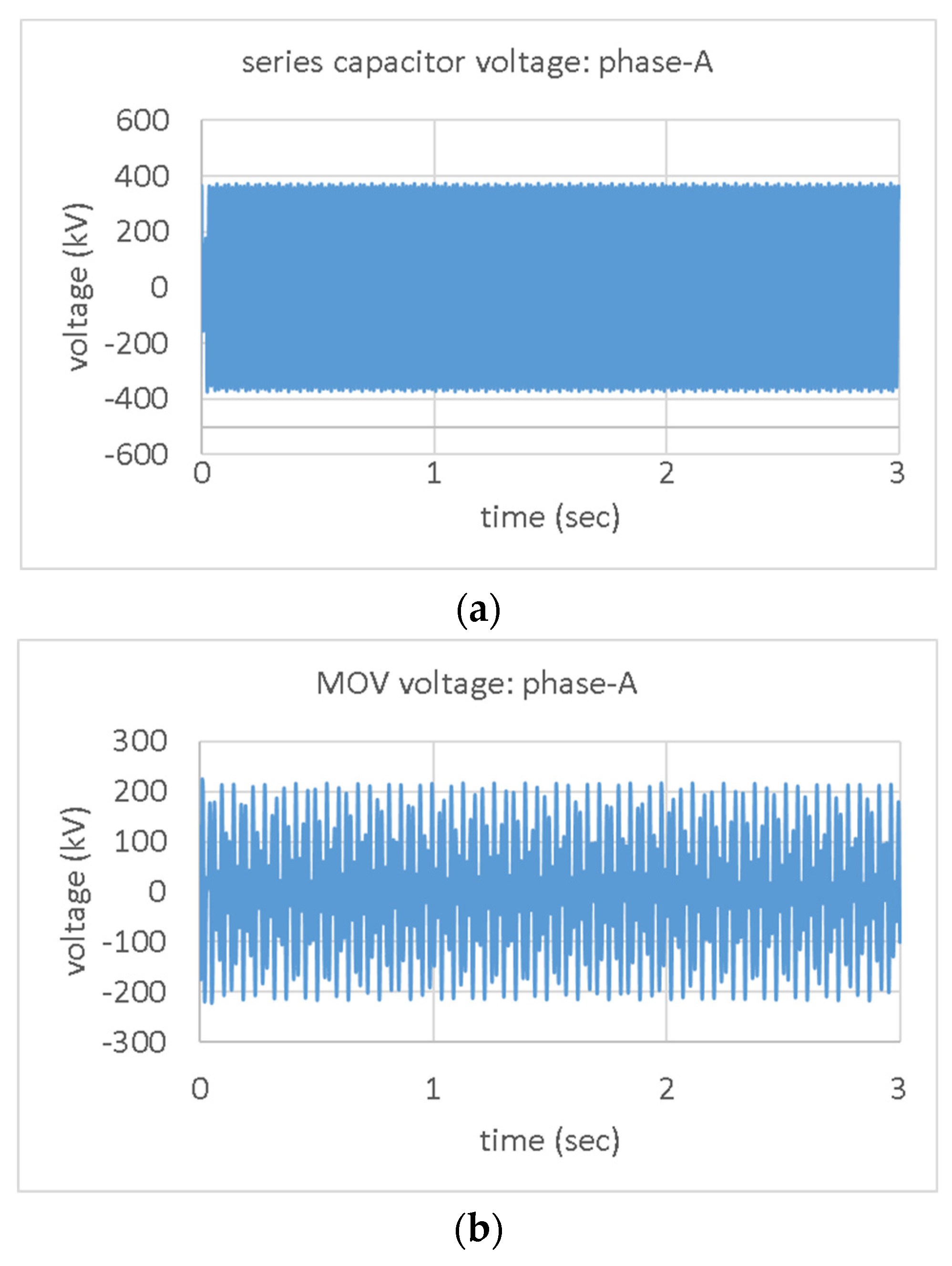
In Figure 19, it shows the currents of the generator, capacitor, and MOV. It can be seen that the MOV shares excessive currents following the fault. This leads to the current flowing through the generator and MOV being limited. In Figure 20, it shows the voltages of the capacitor and the MOV. It is seen that, following the disturbance, the capacitor voltage and the MOV voltage are limited due to the excessive current flowing through the MOV. In Figure 21, it shows the absorbed power of MOV. It can be seen that a high rating is needed for the MOV.
7.2. PMSG Wind Farm Situation
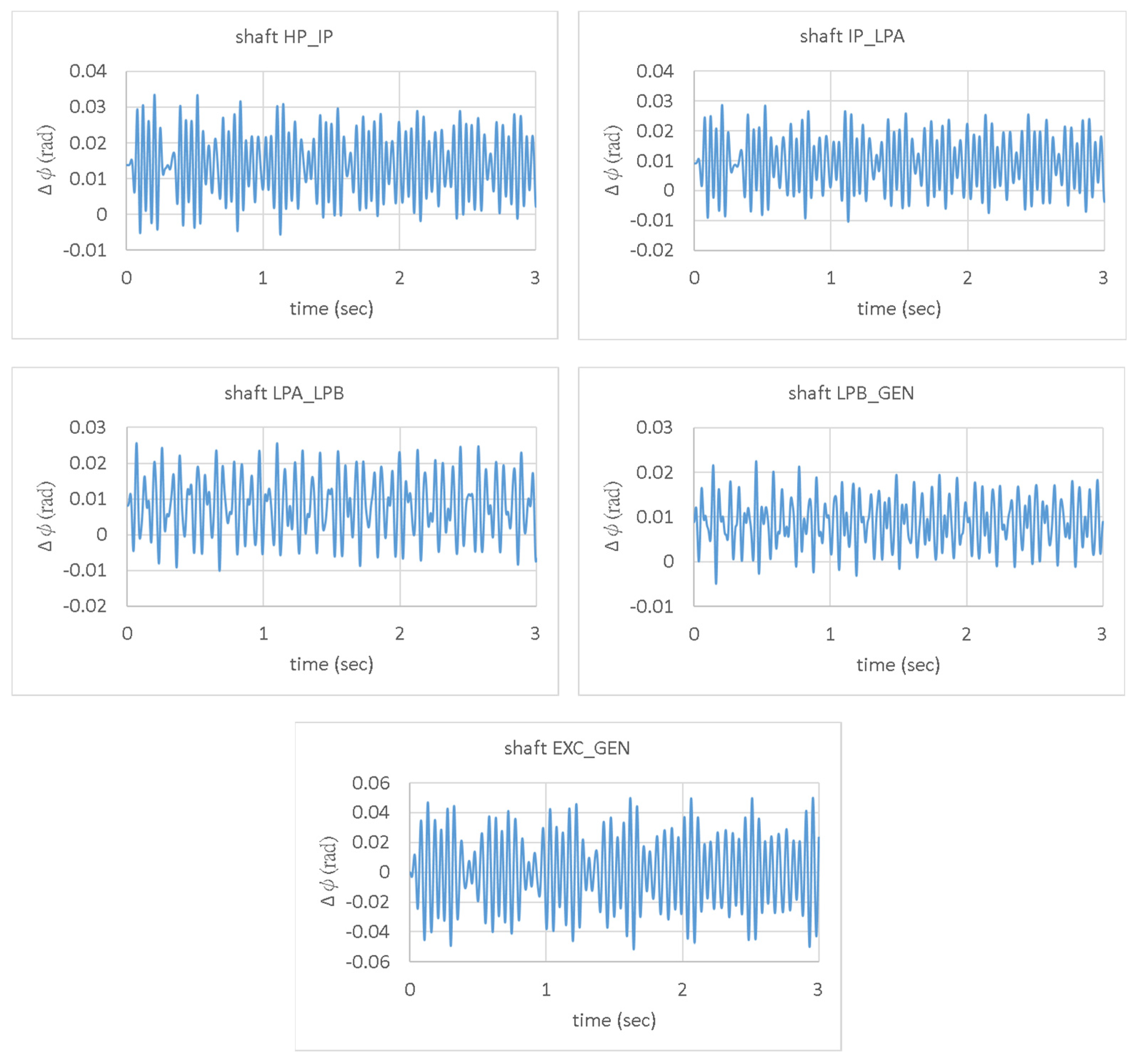
For the integration of a 600 MW PMSG wind farm, the turbine shaft transient responses with MOV are shown in Figure 22. The simulation events remain the same as in Section 7.1. It can be seen that the responses at the HP_IP, the IP_LPA, and the LPB_GEN shafts are obviously unstable. Therefore, the MOV is futile for stabilizing the unstable torsional responses, which is different from the DFIG wind farm situation.
8. Conclusions
The impact of the integration of different types of wind farms into a series compensated transmission system has been studied in this paper. The focus of this paper is placed in the transition period of the energy transition, which is different from the research in the past. In such a special situation, not only is the wind farm integrated into the power system, but also the traditional generators still operate with reduced power. As compared with the previous research, the studies in the paper have four aspects of advancement. The first is that the effect of the penetration rate is further studied in addition to the compensation factor. The relationship between the compensation factor and the penetration rate thus becomes clear. The second finding is that the factors causing sub-synchronous torsional vibrations are caused not only by the IGE of DFIGs but also by the de-rating operations of traditional generator units. Moreover, the influence degree of the two factors has been compared, and which one is more significant has been verified. The third is that the effect of MOV, which is standard equipment in modern series capacitors, on the SSR generated by the DFIG-based wind farm and the series compensated transmission system has been studied and proved to be effective in improving the vibrations. The fourth is that the effect of PMSG wind farms is studied in addition to the DFIG wind farms, which is usually ignored in the SSR issues of series compensated transmission systems. Moreover, the effect of MOV and turbine damping when integrating the two types of wind farm has been studied and proved to be different. In conclusion, it is found in the paper that all the compensation factors, the penetration rate, and the wind farm type play significant roles. Therefore, in order to avoid the sub-synchronous torsional vibrations, one should not only focus on the compensation factor, but also pay attention to the types of wind farm as well as the penetration rate. In Table 8, it summarizes some of the noteworthy results of the comparative studies on the two types of wind farms.
Funding
This research received no external funding.
Data Availability Statement
The study did not report any data.
Conflicts of Interest
The authors declare no conflict of interest.
Appendix A
The induction generator effect is an electrical resonance phenomenon, independent of the generator shaft torsional modes. The generator can interact with the electric power system to result in a negative effective resistance at a natural frequency below the fundamental frequency. If the negative resistance is greater than the network resistance, self-excited sub-synchronous current and electromagnetic torque in the machine can result. IGE can happen to both the induction generators and the synchronous generators.
Appendix A.1. Induction Generator
In Figure A1, it shows the equivalent circuit of an induction generator/motor. The rotor resistance, as shown in (A1), is dependent on the slip ratio(s). If the slip ratio becomes negative, the effective rotor resistance turns negative.
Figure A1.
Equivalent circuit of an induction generator.

Appendix A.2. Synchronous Generator
For a synchronous generator, field and damper winding characteristics can contribute to IGE. At frequencies () below the system frequency (), the effective generator resistance will be negative, as revealed in (A2).
- : d-axis transient open-circuit time constant;
- : system frequency;
- : base frequency;
- : reactance;
- : transient reactance.
References
- Bollen, M.H.J.; Yang, K. Harmonic Aspects of Wind Power Integration. J. Mod. Power Syst. Clean Energy 2013, 1, 14–21. [Google Scholar] [CrossRef]
- Varma, R.K.; Rahman, S.A.; Vanderheide, T.; Dang, M.D.N. Harmonic Impact of a 20-MW PV Solar Farm on a Utility Distribution network. IEEE Power Energy Technol. Syst. J. 2016, 3, 89–98. [Google Scholar] [CrossRef]
- Shi, J.; Lee, W.J.; Liu, X. Generation Scheduling Optimization of Wind-Energy Storage System Based on Wind Power Output Fluctuation Features. IEEE Trans. Ind. Appl. 2018, 54, 10–17. [Google Scholar] [CrossRef]
- Lin, J.; Sun, Y.; Song, Y.; Gao, W.; Sorensen, P. Wind Power Fluctuation Smoothing Controller Bbased on Risk Assessment of Grid Frequency Deviation in an Isolated system. IEEE Trans. Sustain. Energy 2013, 4, 379–392. [Google Scholar] [CrossRef]
- Vittal, E.; O’Malley, M.; Keane, A. A Steady-State Voltage Stability Analysis of Power Systems with High Penetrations of Wind. IEEE Trans. Power Syst. 2010, 25, 433–442. [Google Scholar] [CrossRef]
- Chowdhury, M.A.; Shen, W.; Hosseinzadeh, N.; Pota, H.R. Transient Stability of Power System Integrated with Doubly Fed Iinduction Generator Wind Farms. IET Renew. Power Gener. 2015, 9, 184–194. [Google Scholar] [CrossRef]
- Yang, L.; Xu, Z.; Ostergaard, J.; Dong, Z.Y.; Wong, K.P. Advanced Control Strategy of DFIG Wind Turbines for Power System Fault Ride Through. IEEE Trans. Power Syst. 2012, 27, 713–722. [Google Scholar] [CrossRef]
- Conroy, J.F.; Watson, R. Low-Voltage Ride-Through of a Full Converter Wind Turbine with Permanent Magnet Generator. IET Renew. Power Gener. 2007, 1, 182–189. [Google Scholar] [CrossRef]
- Tsourakis, G.; Nomikos, B.M.; Vournas, C.D. Effect of Wind Parks with Doubly Fed Asynchronous Generators on Small-Signal Stability. Electr. Power Syst. Res. 2009, 79, 190–200. [Google Scholar] [CrossRef]
- Bu, S.Q.; Du, W.; Wang, H.F.; Chen, Z.; Xiao, L.Y.; Li, H.F. Probabilistic Analysis of Small-Signal Stability of Large-Scale Power Systems as Aaffected by Penetration of Wind Generation. IEEE Trans. Power Syst. 2012, 27, 762–770. [Google Scholar] [CrossRef]
- Hughes, F.M.; Anaya-Lara, O.; Jenkins, N.; Strbac, G. A Power System Stabilizer for DFIG-Based Wind Generation. IEEE Trans. Power Syst. 2006, 21, 763–772. [Google Scholar] [CrossRef]
- Fernandez, R.D.; Mantz, R.J.; Battaiotto, P.E. Impact of Wind Farms on a Power Ssystem. An Eigenvalue Analysis Approach. Renew. Energy 2007, 32, 1676–1688. [Google Scholar] [CrossRef]
- Jafarian, M.; Ranjbar, A.M. Interaction of the Dynamics of Doubly Fed Wind Generators with Power System Electromechanical Oscillations. IET Renew. Power Gener. 2013, 7, 89–97. [Google Scholar] [CrossRef]
- Mehta, B.; Bhatt, P.; Pandya, V. Small Signal Stability Analysis of Power Systems with DFIG Based Wind Power Penetration. Int. J. Electr. Power Energy Syst. 2014, 58, 64–67. [Google Scholar] [CrossRef]
- Faried, S.O.; Billinton, R.; Aboreshaid, S. Probabilistic Evaluation of Transient Stability of a Power System Incorporating Wind Farms. IET Renew. Power Gener. 2010, 4, 299–307. [Google Scholar] [CrossRef]
- Li, H.; Zhao, B.; Yang, C.; Chen, H.W.; Chen, Z. Analysis and Estimation of Transient Sstability for a Grid-Connected Wind Turbine with Induction Generator. Renew. Energy 2011, 36, 1469–1476. [Google Scholar] [CrossRef]
- Dicorato, M.; Forte, G.; Trovato, M. Wind Farm Stability Analysis in the Presence of Variable-Speed Generators. Energy 2012, 39, 40–47. [Google Scholar] [CrossRef]
- Kuang, H.; Zheng, L.; Li, S.; Ding, X. Voltage Stability Improvement of Wind Power Grid-Connected Ssystem Using TCSC-STATCOM control. IET Renew. Power Gener. 2019, 13, 215–219. [Google Scholar] [CrossRef]
- Ren, W.; Larsen, E. A Refined Frequency Scan Approach to Sub-Synchronous Control Interaction (SSCI) Study of Wind Farms. IEEE Trans. Power Syst. 2016, 31, 3904–3912. [Google Scholar] [CrossRef]
- Zhang, X.; Xie, X.; Shair, J.; Liu, H.; Li, Y.; Li, Y. A Grid-Side Subsynchronous Damping Controller to Mitigate Unstable SSCI and its Hardware-in-the-Loop Tests. IEEE Trans. Sustain. Energy 2020, 11, 1548–1558. [Google Scholar] [CrossRef]
- Li, P.; Wang, J.; Xiong, L.; Ma, M.; Wang, Z.; Huang, S. Robust Sub-Synchronous Damping Controller to Mitigate SSCI in Series-Compensated DFIG Based Wind Park. IET Gener. Transm. Distrib. 2020, 14, 1762–1769. [Google Scholar] [CrossRef]
- Varma, R.K.; Moharana, A. SSR in Double-Cage Induction Generator-Based Wind Farm Connected to Series-Compensated Transmission Line. IEEE Trans. Power Syst. 2013, 28, 2573–2583. [Google Scholar] [CrossRef]
- Mahalakshmi, R.; Sindhu Thampatty, K.C. Analysis of SSR in Grid Integrated Series Compensated SCIG Based Wind Turbine Generators-Alaboratory Model. Int. J. Electr. Eng. Inform. 2021, 13, 336–353. [Google Scholar]
- Moharana, A.; Varma, R.K.; Seethapathy, R. Subsynchronous Impact of Series Compensation on Induction Generator Based Wind Farm. Electr. Power Compon. Syst. 2013, 41, 1041–1058. [Google Scholar] [CrossRef]
- Chen, W.; Teng, Z.; Zhao, J.; Qiu, J. Small-Signal Performance of Type 4 Wind Turbine Generator-Based Clusters in Power Systems. Energies 2018, 11, 1486. [Google Scholar] [CrossRef] [Green Version]
- Hansen, A.D.; Iov, F.; Sorensen, P.; Cutululis, N.; Jauch, C.; Blaabjerg, F. Dynamic Wind Turbine Models in Power System Simulation Tool, 2nd ed.; Riso-R-1400; Riso National Laboratory, Technical University of Denmark: Roskilde, Denmark, 2007. [Google Scholar]
- Hamon, C. Doubly-Fed Induction Generator Modeling and Control in DigSilent Power Factory. Master’s Thesis, KTH School of Electrical Engineering, Stockholm, Sweden, 2010. [Google Scholar]
Figure 1.
System studied.

Figure 2.
Lumped mass-damping-spring model of the turbine-and-generator mechanism.

Figure 3.
DFIG model.

Figure 4.
PMSG model.

Figure 5.
Torsional vibrations under the normal situation.

Figure 6.
Generator current and its frequency spectrum.

Figure 7.
Damping ratios of torsional modes for the incorporation of the DFIG wind farm.

Figure 8.
(a) Shaft torsional responses for the integration of a 100 MW DFIG wind farm. (b) Shaft torsional responses for the integration of a 200 MW DFIG wind farm.
Figure 8.
(a) Shaft torsional responses for the integration of a 100 MW DFIG wind farm. (b) Shaft torsional responses for the integration of a 200 MW DFIG wind farm.


Figure 9.
Generator currents and torsional vibrations for different penetration rates of DFIG wind power, (a) 12.5%, (b) 37.5%, (c) 62.5%, and (d) 87.5%.
Figure 9.
Generator currents and torsional vibrations for different penetration rates of DFIG wind power, (a) 12.5%, (b) 37.5%, (c) 62.5%, and (d) 87.5%.


Figure 10.
Frequency of resonance current.

Figure 11.
Generator current, (a) without and (b) with 100 MW DFIG wind farm.

Figure 12.
Shaft torsional responses for the integration of a 100 MW DFIG wind farm under the compensation of Bc = 0.0135 S.
Figure 12.
Shaft torsional responses for the integration of a 100 MW DFIG wind farm under the compensation of Bc = 0.0135 S.

Figure 13.
Damping ratios of torsional modes for the integration of the PMSG wind farm.

Figure 14.
Damping ratios of mode 5 for the integration of different types of wind farm.

Figure 15.
(a) Shafts torsional responses for the integration of 400 MW PMSG wind farm. (b) Shafts torsional responses for the integration of 600 MW PMSG wind farm.
Figure 15.
(a) Shafts torsional responses for the integration of 400 MW PMSG wind farm. (b) Shafts torsional responses for the integration of 600 MW PMSG wind farm.


Figure 16.
Torsional vibrations for different penetration rates of PMSG wind power. (a) 12.5%. (b) 37.5%. (c) 62.5%. (d) 87.5%.
Figure 16.
Torsional vibrations for different penetration rates of PMSG wind power. (a) 12.5%. (b) 37.5%. (c) 62.5%. (d) 87.5%.

Figure 17.
The MOV characteristics.

Figure 18.
Turbine shaft transient responses with MOV for DFIG wind farm integration.

Figure 19.
Currents of (a) generator, (b) capacitor, and (c) MOV.

Figure 20.
Voltages of (a) capacitor and (b) MOV.

Figure 21.
Absorbed power of MOV.

Figure 22.
Turbine shaft transient responses with MOV for the incorporation of PMSG wind farm.


Table 1.
Parameters of the mass-damping-spring model.
| Parameter | Value |
|---|---|
| JHP | 1166.619 kgm2 |
| DHP | 200 Nm/rad |
| KHP_IP | 45,693,376 Nms/rad |
| JIP | 1953.917 kgm2 |
| DIP | 200 Nm/rad |
| KIP_LPA | 82,682,688 Nms/rad |
| JLPA | 10,783.35 kgm2 |
| DLPA | 400 Nm/rad |
| KLPA_LPB | 123,182,504 Nms/rad |
| JLPB | 11,104.15 kgm2 |
| DLPB | 400 Nm/rad |
| KLPB_GEN | 167,732,544 Nms/rad |
| JEXC | 429.6976 kgm2 |
| DEXC | 0 Nm/rad |
| KEXC_GEN | 6,675,404 Nms/rad |
Table 2.
Torsional modes of the steam turbine generator unit.
| Mode | Frequency | Damping Ratio |
|---|---|---|
| 1 | 47.5 Hz | 0.001947 |
| 2 | 32.0 Hz | 0.000865 |
| 3 | 25.4 Hz | 0.005457 |
| 4 | 20.2 Hz | 0.000401 |
| 5 | 15.5 Hz | 0.003348 |
Table 3.
Compensation factor.
| Bc (S) | Compensation Factor (%) | Resonant Mode |
|---|---|---|
| 0.00962 | 74 | 20.2 Hz |
| 0.0128 | 56 | 25.4 Hz |
| 0.0175 | 41 | 32.0 Hz |
Table 4.
Stability for various compensation factors and rating factors.
| Compensation Factor | Penetration Rate | ||||
|---|---|---|---|---|---|
| 13% | 16% | 19% | 22% | 25% | |
| 65% | stable | stable | unstable | unstable | unstable |
| 51% | stable | stable | stable | unstable | unstable |
| 47% | stable | stable | stable | unstable | unstable |
| 45% | stable | stable | stable | stable | unstable |
Table 5.
(a) Stability under various turbine mass damping conditions (b) Stability for different turbine shaft damping levels.
Table 5.
(a) Stability under various turbine mass damping conditions (b) Stability for different turbine shaft damping levels.
| (a) Damping Coefficient (Nm/rad) | PWind Farm (MW) | ||||
| DHP | DIP | DLPA | DLPB | 100 | 200 |
| 0 | 0 | 0 | 0 | stable | unstable |
| 200 | 200 | 400 | 400 | stable | unstable |
| 400 | 400 | 800 | 800 | stable | unstable |
| 600 | 600 | 1200 | 1200 | stable | unstable |
| (b) Damping Coefficient (Nm/rad) | PWind Farm (MW) | ||||
| DHP_IP | DIP_LPA | DLPA_LPB | DLPB_GEN | 100 | 200 |
| 0 | 0 | 0 | 0 | stable | unstable |
| 300 | 300 | 300 | 300 | stable | unstable |
| 600 | 600 | 600 | 600 | stable | unstable |
| 1200 | 1200 | 1200 | 1200 | stable | unstable |
Table 6.
Cases for studies on turbine damping.
| Case | DHP | DIP | DLPA | DLPB |
|---|---|---|---|---|
| 1 | 400 | 400 | 800 | 800 |
| 2 | 300 | 300 | 600 | 600 |
| 3 | 200 | 200 | 400 | 400 |
| 4 | 0 | 0 | 0 | 0 |
Note: D in Nm/rad.
Table 7.
(a) Torsional mode damping ratios for case 1. (b) Torsional mode damping ratios for case 2. (c) Torsional mode damping ratios for case 3. (d) Torsional mode damping ratios for case 4.
Table 7.
(a) Torsional mode damping ratios for case 1. (b) Torsional mode damping ratios for case 2. (c) Torsional mode damping ratios for case 3. (d) Torsional mode damping ratios for case 4.
| (a) Penetration Rate | 50% | 62.5% | 75% | 87.5% |
| mode1 | 0.001433 | 0.001145 | 0.000856 | 0.000568 |
| mode2 | 0.000751 | 0.000666 | 0.000579 | 0.000492 |
| mode3 | 0.003264 | 0.00224 | 0.001216 | 0.000191 |
| mode4 | 0.000267 | 0.000201 | 0.000135 | 6.84 × 10⁻⁵ |
| mode5 | 0.002387 | 0.001883 | 0.001374 | 0.000858 |
| (b) Penetration Rate | 50% | 62.5% | 75% | 87.5% |
| mode1 | 0.001113 | 0.000825 | 0.000537 | 0.000249 |
| mode2 | 0.000736 | 0.000658 | 0.000573 | 0.000444 |
| mode3 | 0.002413 | 0.001402 | 0.000385 | −0.000673 |
| mode4 | 0.000240 | 0.000180 | 0.000118 | 0.000043 |
| mode5 | 0.002498 | 0.002109 | 0.001702 | 0.001187 |
| (c) Penetration Rate | 50% | 62.5% | 75% | 87.5% |
| mode1 | 0.000795 | 0.000506 | 0.000218 | −7 × 10⁻⁵ |
| mode2 | 0.000525 | 0.000439 | 0.000353 | 0.000266 |
| mode3 | 0.001364 | 0.000341 | −0.00068 | −0.00171 |
| mode4 | 0.000138 | 7.21 × 10⁻⁵ | 5.88 × 10⁻⁶ | −6.1 × 10⁻⁵ |
| mode5 | 0.001368 | 0.000864 | 0.000355 | −0.00016 |
| (d) Penetration Rate | 37.5% | 50% | 62.5% | 75% |
| mode1 | 0.000444 | 0.000156 | −0.000131 | −0.000419 |
| mode2 | 0.000467 | 0.000397 | 0.000319 | 0.000234 |
| mode3 | 0.000570 | −0.000435 | −0.001446 | −0.002463 |
| mode4 | 0.000104 | 0.000046 | −0.000014 | −0.000076 |
| mode5 | 0.001339 | 0.000969 | 0.000581 | 0.000173 |
Table 8.
Summary of the comparative studies.
| Item | Wind Farm Type | |
|---|---|---|
| DFIG | PMSG | |
| The dominant factor influencing the behavior of steam turbine generator torsional responses | IGE of DFIGs | De-rating operations of steam turbine generators |
| Effect of steam turbine damping on torsional responses of steam turbine generators | Irrelevant | Significant |
| Effect of MOV on torsional responses of steam turbine generators | Significant | Futile |
| Allowable penetration rate that will not give rise to instability | Low | High |
Publisher’s Note: MDPI stays neutral with regard to jurisdictional claims in published maps and institutional affiliations. |
© 2022 by the author. Licensee MDPI, Basel, Switzerland. This article is an open access article distributed under the terms and conditions of the Creative Commons Attribution (CC BY) license (https://creativecommons.org/licenses/by/4.0/).
Share and Cite
MDPI and ACS Style
Lin, C.H. Comparison of Impact on Turbine Shafts Torsional Behavior for Integration of Two Types of Wind Farm into a Series-Compensated Transmission System. Energies 2022, 15, 6796. https://0-doi-org.brum.beds.ac.uk/10.3390/en15186796
AMA Style
Lin CH. Comparison of Impact on Turbine Shafts Torsional Behavior for Integration of Two Types of Wind Farm into a Series-Compensated Transmission System. Energies. 2022; 15(18):6796. https://0-doi-org.brum.beds.ac.uk/10.3390/en15186796
Chicago/Turabian StyleLin, Chi Hsiang. 2022. "Comparison of Impact on Turbine Shafts Torsional Behavior for Integration of Two Types of Wind Farm into a Series-Compensated Transmission System" Energies 15, no. 18: 6796. https://0-doi-org.brum.beds.ac.uk/10.3390/en15186796
Note that from the first issue of 2016, this journal uses article numbers instead of page numbers. See further details here.