
Prototyping and Experimental Investigation of Digital Hydraulically Driven Knee Exoskeleton
by
 ,
,
Rituraj Rituraj
1,*,
Rudolf Scheidl
1,*,
Peter Ladner
2,
Martin Lauber
2 and
Andreas Plöckinger
2 1
Institute of Machine Design and Hydraulic Drives, Johannes Kepler University, 4040 Linz, Austria
2
Linz Center of Mechatronics, 4040 Linz, Austria
*
Authors to whom correspondence should be addressed.
Energies 2022, 15(22), 8695; https://0-doi-org.brum.beds.ac.uk/10.3390/en15228695
Submission received: 31 October 2022
/
Revised: 15 November 2022
/
Accepted: 17 November 2022
/
Published: 19 November 2022
(This article belongs to the Special Issue Application and Analysis in Fluid Power Systems)
Abstract
:Digital hydraulic drives are known for their superior efficiency, power density, and robustness. Such advantages make them an attractive alternative (to electric drives) for actuation of exoskeleton devices. This work presents development of a prototype for such a digital hydraulically driven knee exoskeleton and its experimental testing. The device uses two miniature hydraulic cylinders and a novel mechanism to translate the linear motion to rotary motion. The device is controlled via a passive control method in the stance phase and a simplified model predictive control method in the swing phase. In this work, the design of the exoskeleton device is optimized with respect to compactness and weight. Next, the features of the design are further refined to ensure that the device is able to support the operational loads. This design is then realized into a prototype with a mixture of inhouse manufactured parts and procured components. Finally, via experimental tests, the performance of the design and the control strategy are investigated. Certain drawbacks related to valve size and overall weight are observed in the prototype, which will be addressed in future studies.

1. Introduction
Exoskeletons are wearable devices that augment the physical strength of their wearers. Such devices are used in a wide variety of applications. The medical application constitutes rehabilitation of the motion and strength of the limbs of patients suffering from limb injuries and post-stroke gait dysfunction [1,2]. Furthermore, exoskeletons are used by industry workers to help them in lifting heavy objects and performing strenuous activities without risking fatigue and injuries [3]. Soldiers, firefighters, and rescue workers can also benefit from exoskeletons for these reasons [4,5].
Exoskeleton devices of different types and capabilities have been developed by both researchers and industries in the past. A systematic review of past exoskeletons can be found in [6]. This reference as well as an internal literature survey by the authors’ research group [7] reveal that most of the powered exoskeleton devices being researched and available in the market are electro-mechanically driven.
However, hydraulic drives offer key advantages compared to electro-mechanical drives that can make them a better alternative drive technology for powered exoskeletons. Hydraulic drives are power-dense, which can allow a significant reduction in the mass and space occupied by the exoskeleton device. Moreover, hydraulic drives can be easily configured for energy recuperation functionality, which improves the efficiency of the drive, thus allowing a reduction in the size of the power source. Furthermore, hydraulic drives facilitate motion locking without power supply. Finally, damped motion is easily achievable with hydraulic drives, which allows for smooth and natural motion patterns.
Nevertheless, a number of challenges have prevented hydraulically driven exoskeletons from dominating the exoskeleton market. First, novel hydro-mechanical designs need to be developed that allow integration of the hydraulic drive in the exoskeleton device in a compact fashion. Second, miniature hydraulic components are needed to assemble a compact lightweight hydraulic drive. Third, fast and efficient control strategies appropriate for the hydraulic drives are needed for actuation of the exoskeleton. Last but not least, the image of hydraulics as a big, heavy, and obsolete technology needs revamping, which, until now, has prevented most researchers from pursuing hydraulic drives as an option for exoskeleton actuation.
One of the earliest hydraulically driven exoskeletons was the Berkeley Lower Extremity Exoskeleton (BLEEX), developed at the University of California, Berkeley [8,9,10]. This exoskeleton augmented the power at the hip, knee, and ankle joints. Further improvements led to development of exoskeleton devices ExoHiker and ExoClimber, which were claimed to be more comfortable to the wearers [11]. Around the same time, the company Sarcos unveiled its full-body exoskeleton XOS for military applications [12]. While BLEEX used linear hydraulic actuators and mechanisms for motion transformation, XOS used rotary actuators directly at the limb joints [13]. Recent works on hydraulically driven exoskeletons have focused on the control methods [14,15,16,17], development of compact hydraulic power units [18], and alternate working fluids [19]. However, a key limitation of these exoskeleton devices is that they use traditional servovalve-based resistance control, which is known for its poor efficiency. To overcome this limitation of traditional hydraulic systems, Kaminaga et al. proposed electro-hydraulic systems for actuation of joints in humanoid robots [20] followed by knee exoskeletons [21]. The design and control was focused particularly on achieving enhanced back-drivability [22]. The knee joint power assist exoskeleton developed by them used rotary actuators (vane motors) at the knee joint [23,24] and consisted of additional passive joints to allow secondary knee movements [25]. However, usage of hydraulic motors presents the challenges of internal leakages (leading to efficiency and controllability concerns) and low compactness. Therefore, recently, Lee et al. [26] and Jiang et al. [27] have explored electro-hydraulic systems with hydraulic cylinders instead of hydraulic motors for actuation of exoskeleton devices. In their recent knee exoskeleton design, Lee et al. [28] added a multi-axial structure at the knee joint to minimize misalignments. Last, Sun et al. [29] proposed a lightweight electrohydrostatic actuator (LEHA) for knee exoskeletons where they eliminated some accessory components of traditional EHA and custom-designed components to reduce the weight and volume of their exoskeleton device.
In recent decades, digital hydraulics has emerged as an innovative technology that promises several advantages compared to the traditional hydraulics technologies in terms of high force and power density, reliability, robustness, and inexpensiveness [30]. These advantages make digital hydraulics an ideal candidate for actuation of exoskeleton devices, where compactness and robustness of the drive, lightness of the power source, and precision of motion are key requirements. The leg exoskeleton developed by Cao et al. [31], which used switching control, can be considered as the earliest implementation of digital hydraulic concepts in the exoskeleton devices.
In recent years, the authors’ research group has made efforts to leverage the aforementioned advantages of digital hydraulics in development of lower limb exoskeleton devices. In 2017, the first design of a digital hydraulically driven knee exoskeleton was proposed [7,32]. This exoskeleton consisted of a digital hydraulic cylinder driving the knee joint via a four-bar linkage mechanism. A key limitation of this design was the need of multi-chamber cylinders to realize the digital cylinder, which are known to be expensive. In 2021, the authors proposed a novel design of knee exoskeleton that consists of a unique mechanism to enable digital actuation of the exoskeleton with two simple hydraulic cylinders instead of a multi-chamber cylinder [33].
In the work presented in this article, the authors move towards realization of the aforementioned exoskeleton design. The design is first optimized with respect to its size and weight. Next, refined designs of each of the parts are developed, with a focus on their load carrying capabilities. Afterwards, a prototype of the exoskeleton device based on this design is fabricated. Finally, experimental studies are conducted to investigate the performance of the device and the control strategy proposed by the authors elsewhere [34].
Overall, this article showcases successful realization of the concept of digital hydraulically driven exoskeletons. It presents to the research community and industry a power-dense hydraulic alternative to the electromechanically driven exoskeletons. Furthermore, this work brings digital hydraulics technology (and with it, its several advantages) into the field of hydraulically driven exoskeletons.
This article is divided into eight sections including this introductory section. The design of the knee exoskeleton device is presented in Section 2. Section 3 presents the details of the design optimization study. The information related to prototype development is presented in Section 4. The control strategy proposed by the authors is briefly presented in Section 5. The experimental tests and the results are described in Section 6. Section 7 presents a discussion of the work presented in this article in relation to past works. Finally, the key conclusions of this work are provided in Section 8.
2. Knee Exoskeleton Design
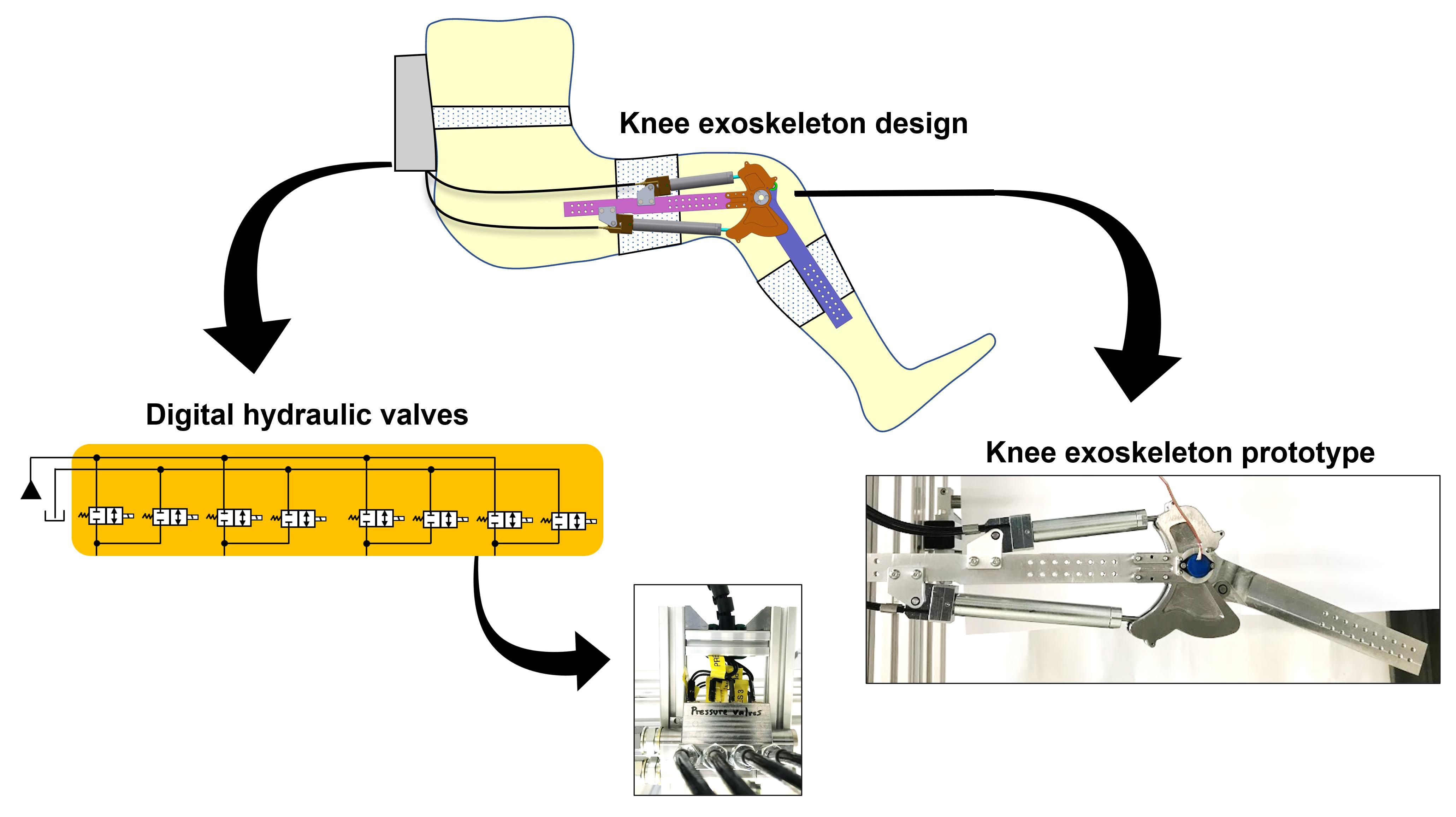
The knee exoskeleton design conceived by the authors is shown in Figure 1. The design consists of the thigh and shank parts, which are attachable to the corresponding limb parts of a human. The parts are connected via a revolute joint at the knee. Motion actuation is performed by two mechanisms, each consisting of a hydraulic cylinder and a connecting rod. The joint between the cylinder rod and connecting rod for each mechanism contains a guide pin that is constrained to move along a curved path. This path is present in the form of grooves on the guide plates. There are two guide plates on either side of the mechanisms to support the guide pins (the front guide plate is hidden in Figure 1). The geometric feature of the guide curve (along with the length of the linkages in the mechanisms) dictates the transmission ratios of the mechanisms (Section 2.2).
2.1. Hydraulic Drive
As shown in Figure 1, the digital hydraulic system driving the exoskeleton device consists of a pressure source, tank, digital valves (highlighted in yellow), and two hydraulic cylinders. The digital 2/2-way valves connect each cylinder chamber to the pressure source and tank.
There are eight 2/2-way valves in the hydraulic drive, and each valve can have two possible positions (on and off). Thus, the drive has 16 unique valve configurations, as illustrated in Figure 2.
2.2. Transmission Ratio
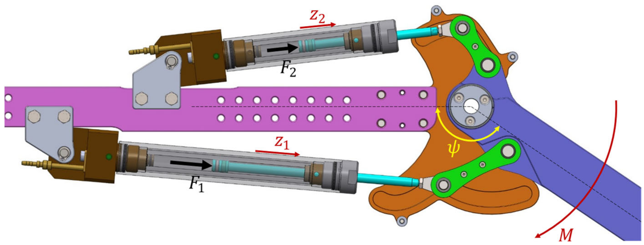
The transmission ratio of a mechanism () is defined as the ratio of the linear motion of the pistons in the cylinders and the angular motion of the knee joint:
where is the piston position in the cylinder and is the knee angle, as indicated in Figure 3.
The transmission ratio establishes the following relationship between the forces at the hydraulic cylinders () and the torque delivered at the knee joint () [33]:
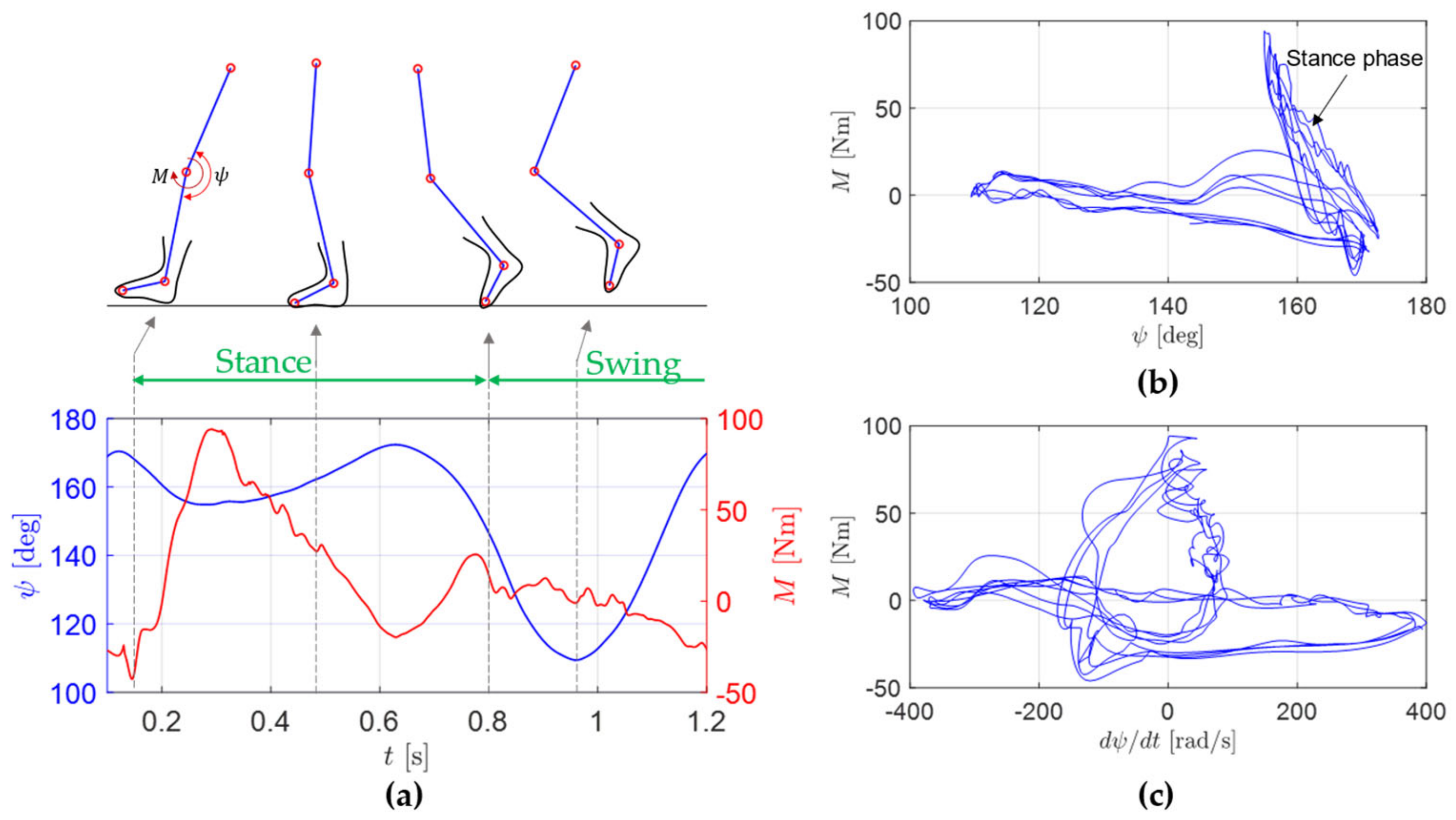
To determine this knee torque requirement, the limb motion dynamics data from HuMoD database [35] are utilized. The database developed by researchers at TU Darmstadt, Germany [36] contains the biomechanical measurements (motion of the limb joints during typical gait cycles) and anthropomorphic parameters (length and mass of the limb parts) of the test subjects. This information is utilized in a multi-body numerical model of the human leg developed by the authors (a brief description is present in Appendix A) to determine the knee torque requirement in a typical gait cycle.
Figure 4a shows the knee angle and knee torque variation over a gait cycle. In the stance phase (where the foot touches the ground and the leg supports the load of the body), the knee torque requirement is high (up to 100 Nm). In contrast, in the swing phase (where the foot is off the ground), the knee torque remains low.
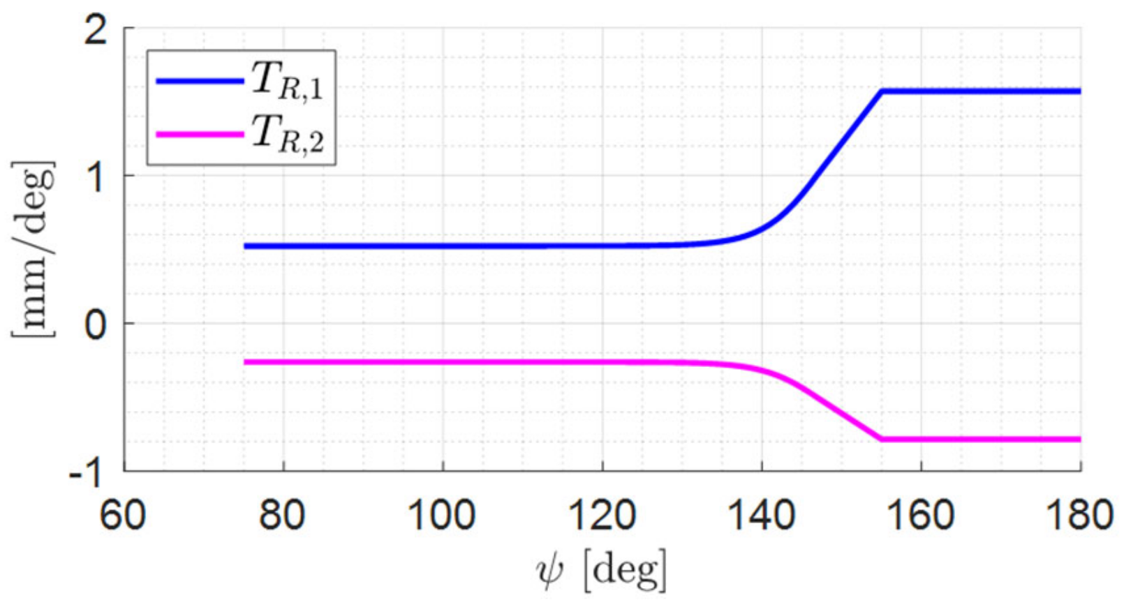
It is further notable from Figure 4b that the knee torque is high for knee angle and remains low for lower knee angles. This allows the mechanisms to be designed such that their transmission ratios are low for and high for (Figure 5). Low transmission ratio for the majority of the knee angular span allows a smaller piston stroke of the hydraulic cylinders (as per Equation (1)), whereas high transmission ratio at peak torque requirement ensures a low hydraulic force requirement (as per Equation (2)), which enables using small hydraulic cylinders (in terms of bore size) working at medium pressure levels (200 bar).
The relationship between the transmission ratios of the two mechanisms is chosen as:
with the negative sign indicating the opposite motion of the pistons for a given knee angular motion. Consequently, the knee torque expression from Equation (2) simplifies to:
Here, the cylinder force is:
If the area ratio of the cylinders is chosen as:
Equation (4) simplifies to:
From this expression, the cylinder bore diameter requirement can be determined. In particular, for the source pressure of 200 bar and the transmission ratio characteristic from Figure 5, the maximum torque (100 Nm) can be achieved with cylinders of bore diameter 8 mm.
Next, defining the effective force as,
the following expression is obtained:
For each of the 16 valve configurations shown in Figure 2, each of the pressure terms in Equation (9) is either equal to the source pressure or the tank pressure. Thus, each valve configuration corresponds to a unique effective force. Figure 6 shows uniform stepping of the effective force, which is a direct result of the conditions imposed on the transmission ratios (Equation (3)) and the area ratios (Equation (6)).
3. Design Optimization Study
A major requirement of the exoskeleton device is that it should be compact and lightweight while providing its necessary function. To determine such a compact and lightweight design of the knee exoskeleton proposed by the authors, a design optimization study is conducted.
3.1. Objective Functions
For the user’s comfort, it is important that the lateral width of the exoskeleton device (indicated as in Figure 7) is as small as possible. In the exoskeleton design, this dimension is decided by the maximum distance between the guide curves of the two mechanisms. Thus, the first optimization objective is:
where and represent the guide curves of the two mechanisms.
The second optimization objective is related to loading at the guide curves. As shown in the inset of Figure 7, the guide curve needs to support the loads from the hydraulic cylinder and the connecting rod. Supporting higher loads will require thicker plates made of stronger material, which will lead to an increase in the weight of these plates. Thus, minimization of the load on the guide plate forms the second objective.
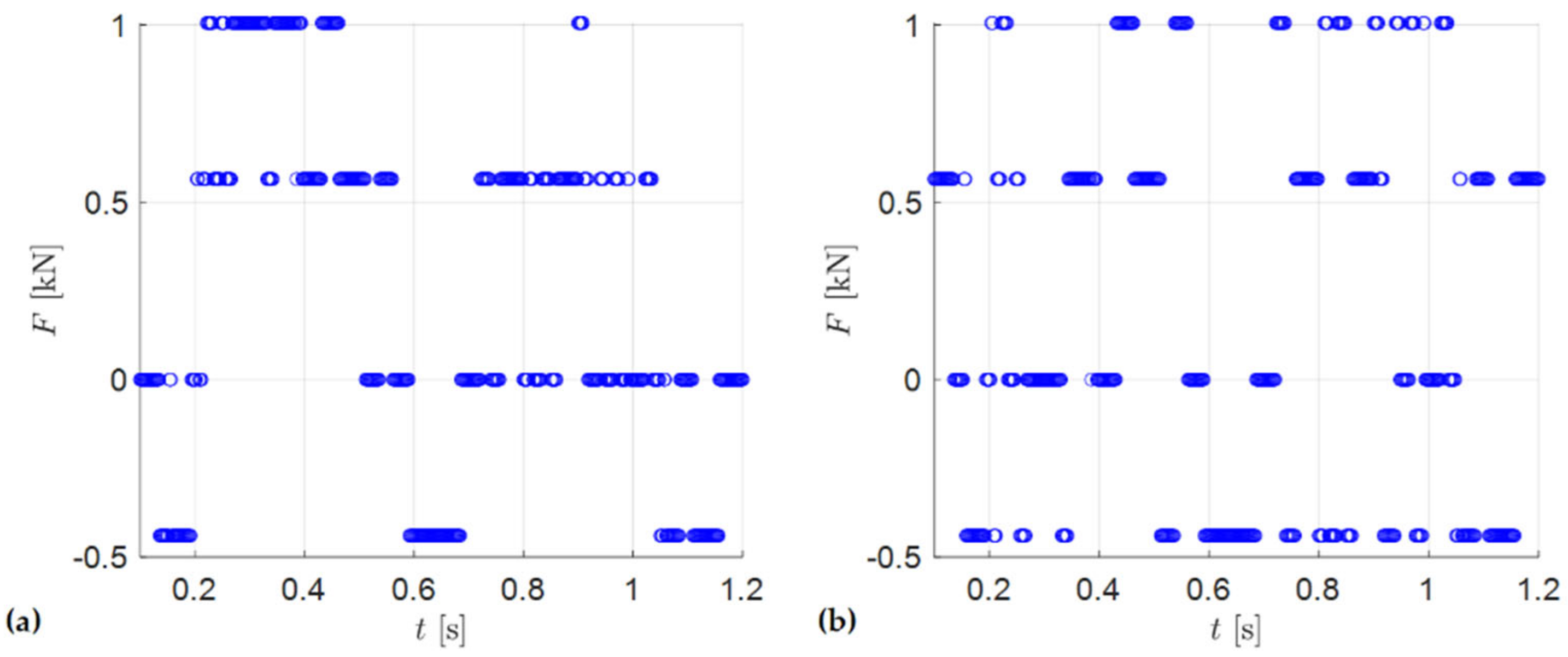
To determine the load on the guide plates and the contact force , the gait cycle is divided into discrete time steps. For each time step in a gait cycle, from the knowledge of the knee torque requirement and the mechanism transmission ratio, the effective force requirement is determined (Equation (8)). The nearest discrete force level deliverable from the drive (shown in Figure 6) is chosen and the corresponding force from each cylinder () is determined. Figure 8 shows the forces for each cylinder, where the four levels of forces observed are the result of four pressurization cases: (a) ; (b) ; (c) ; (d) .
Next, the contact force at the guide plate is evaluated as:
where and are the angles that the cylinder and connecting rod form with the tangent to the guide curve (as illustrated in the inset of Figure 7).
Thus, the second objective function is:
3.2. Optimization Variables
The design variables for the optimization study are the dimensions and , as indicated in Figure 7. Table 1 shows the bounds imposed on these variables in the optimization process. The lower bounds of the crank lengths ( and ) are set to 20 mm to allow enough space at the knee joint for installation of an angle sensor (shown in Section 4.4). The lower bounds of the connecting rods ( and ) are set to 20 mm to allow enough space for realization of the revolute joints at their ends. The upper bounds of these linkages are set to 60 mm since linkages longer than this will lead to designs with lateral width () much higher than the typical width of the knee.
The distance of each cylinder base mounting from the knee joint ( and ) is influenced by the stroke of that cylinder. The stroke of each cylinder is determined from the transmission ratio of the respective mechanism and the angular span of the knee joint. For the knee angle range , the stroke values of the two cylinders are determined to be 90 mm and 45 mm. The higher values in the bounds of and account for the extra distance due to the lengths of the cylinder base and cylinder rods in extension. The y-coordinates of the cylinder base mounting ( and ) are limited to [30, 40] mm range. The lower bound ensures that a realistic mounting of the cylinders on the shank part is achievable, whereas the higher bound ensures the compactness of the device.
3.3. Optimization Constraints
The following constraints are imposed on the optimization problem:
- The design must satisfy the transmission ratio requirements described in Section 2.2.
- The design must be kinematically feasible for the full range of knee motion.
- During the full range of knee motion, interference between different parts of the exoskeleton device must be avoided.
- It can be observed that the groove for mechanism 1 has a relatively sharp peak near the middle. If the curvature of the groove at this peak becomes too high, the knee motion may experience jerky behavior when the guide pin passes through this region. To avoid this, the curvature of the groove must be smaller than a certain value (170 m−1 is considered as an appropriate limit).
3.4. Optimization Procedure and Results
The multi-objective optimization problem described in the preceding subsections is solved using the NSGA II algorithm [37] in MATLAB environment. The initial design space is populated with 1000 designs and the optimization algorithm is executed for 100 generations.
Figure 9 shows the results obtained from the optimization study in terms of the approximate pareto-front between the two objectives (minimization of the device width and minimization of the contact force at the guide plates). The existence of the pareto-front indicates that there is a clear trade-off between these objectives and no single design performs the best with respect to both the objectives.
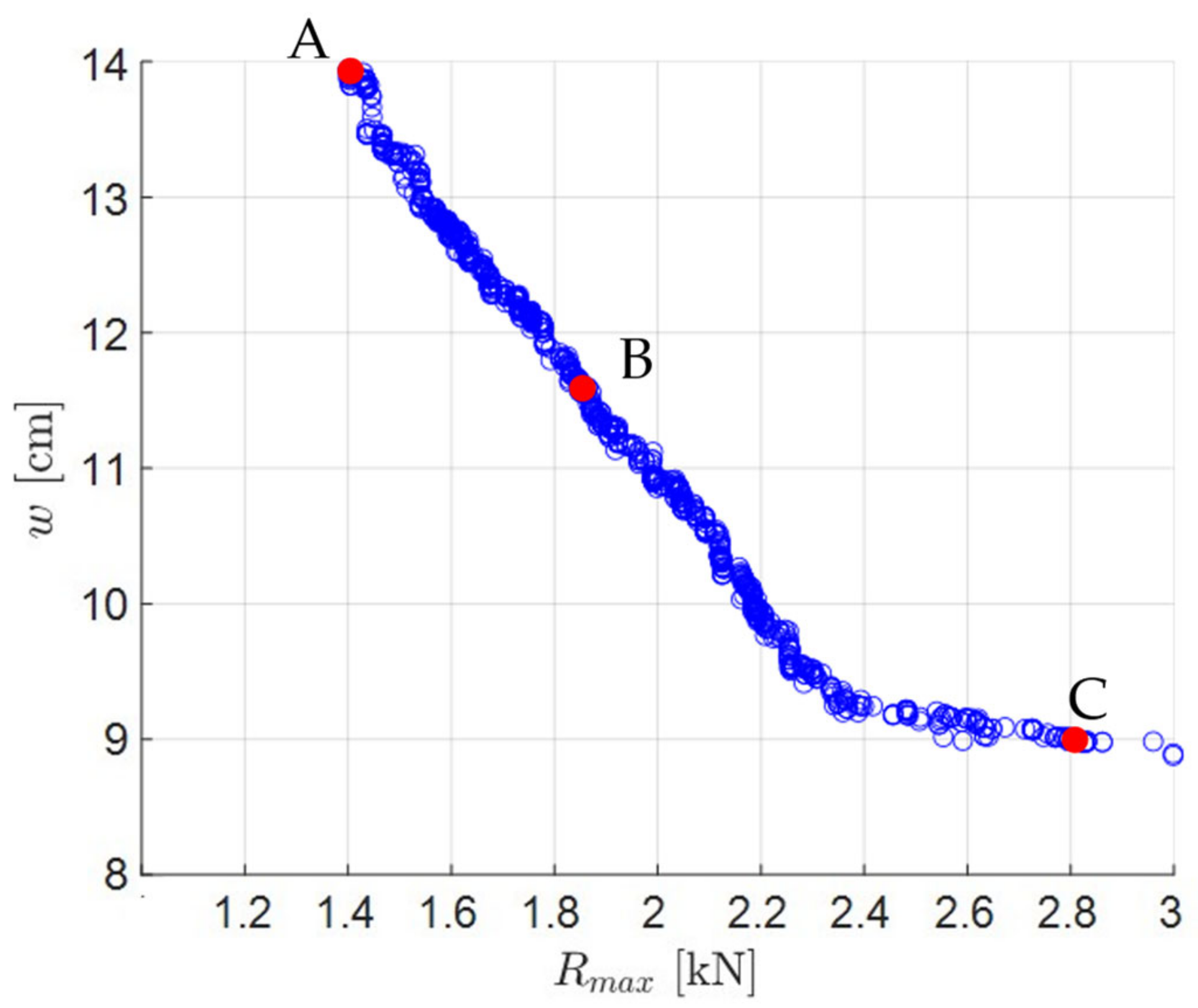
Three designs chosen from the pareto-front are shown in Figure 10. Design A has a smaller contact force (1.4 kN) but is much larger in size (14 cm width). On the other hand, design C has a smaller size (9 cm width) but exhibits high contact force (2.8 kN). Design B is a good compromise between the two extreme designs ( kN cm) and, hence, is chosen in this work. The illustrations of the exoskeleton device in Figure 1, Figure 3, and Figure 7 show this chosen design. The values of the design variables for this design are reported in Table 2.
It is notable that the inverse relationship between the device size and contact force in Figure 9 is the result of the fact that, as the size of the device is reduced, the angle between the connecting rod and guide groove ( in Figure 7) needs to increase, resulting in the increase in the contact force at the guide groove. This observation is illustrated for the three designs in Figure 10, where the value of for the highest knee angle configuration is reported.
4. Prototype Development
The exoskeleton design chosen from the optimization study in the previous section is realized in the form of a prototype. In the following subsections, key details related to the development/procurement of each component of the prototype and its integration in the prototype are presented.
4.1. Hydraulic Cylinders
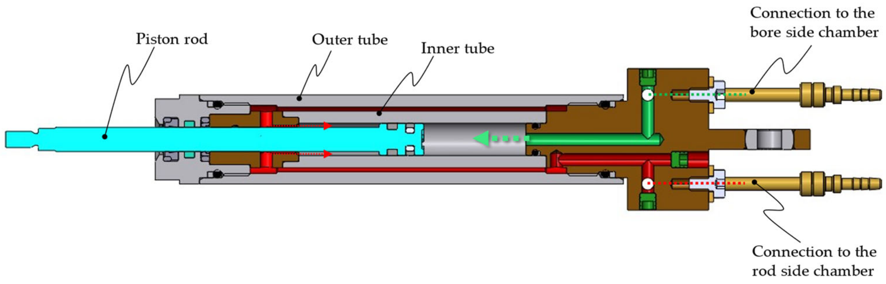
The miniature hydraulic cylinders are obtained from HAWE Micro Fluid GmbH [38]. As shown in Figure 11, the cylinder design is based on the twin-tube principle, which allows location of both bore and rod side chamber ports at the cylinder base. The annular region between the outer and inner tubes allows fluid flow between the rod side chamber and the cylinder base.
The strokes of the cylinders are 90 mm and 45 mm, which fulfils the requirements of the exoskeleton design. The bore and rod diameter of the cylinders are 8 mm and 6 mm, respectively, resulting in the area ratio of 2.29:1. As this cylinder is an off-the-shelf component from HAWE, the desired area ratio of 4:1 could not be fulfilled. This results in non-uniformity of the force steps deliverable by the hydraulic drive. This non-uniformity is visible in Figure 12, which shows the forces for different valve configurations. The interpretation of each valve configuration in terms of the state of pressurization/depressurization of each of the cylinder chambers is illustrated in Table 3. From Figure 12, the force step non-uniformity is moderate and, thus, is tolerable for the sake of the first prototype.
4.2. Linkage Parts and Guide Plates
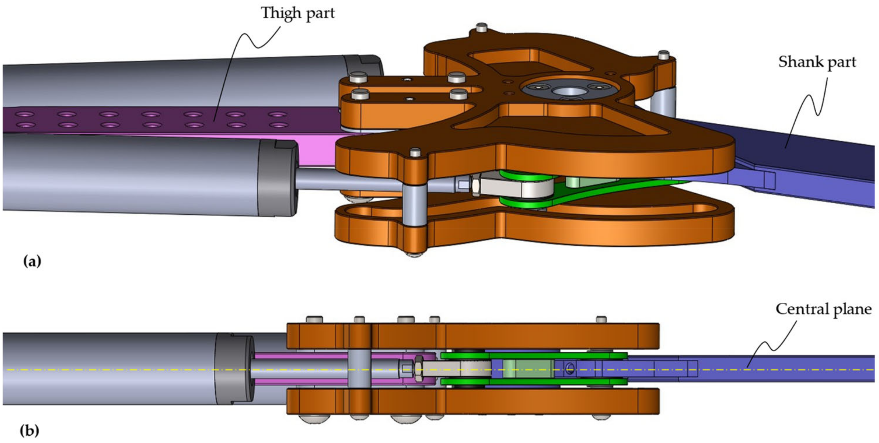
In the mechanical design of the exoskeleton device, the thigh part, the shank part, and the hydraulic cylinders are aligned on the same plane (referred to as the central plane in Figure 13). This prevents the rise of any lateral moment during exoskeleton operation.
To link these coplanar cylinder rod and shank parts, the connecting rod part is realized via two individual parts that are interconnected via spacer elements (Figure 14). Similarly, there are two guide plates that are interconnected via spacer elements (Figure 13). On the upper side (mechanism 2 side) of the device, there are two such connections. In contrast, the lower side (mechanism 1 side) has only one interconnection due to the space constraint arising from the presence of the shank part on this side.
To determine the appropriate dimensions of the key loaded parts (i.e., connecting rod elements, guide plates, and shank) and their material type, stress analyses are conducted using Finite Element Analysis (FEA) tool in Solidworks Simulation environment [39]. Brief details of this study are presented in the following subsections.
4.2.1. Connecting Rod Linkage
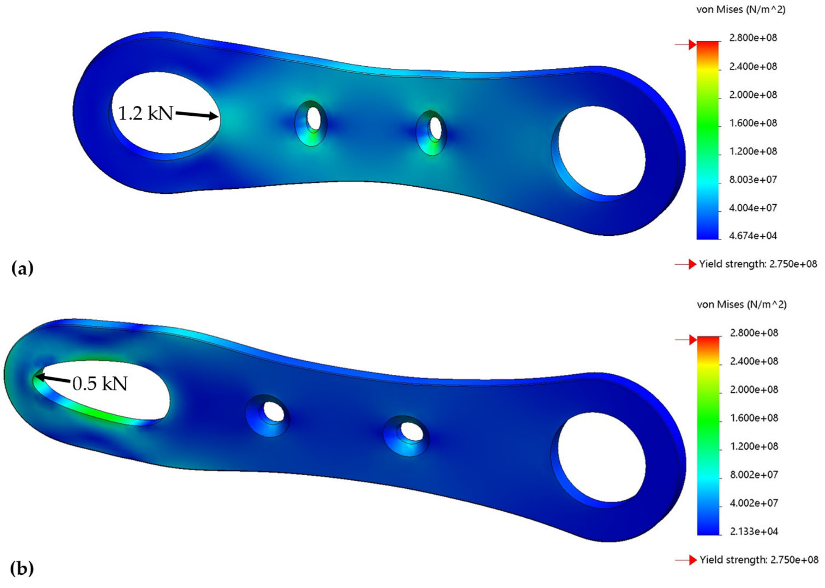
From the knowledge of the force at the hydraulic cylinder (Figure 8) and the orientation of the cylinder and the connecting rod (inset of Figure 7), the force experienced by the connecting rod linkage is determined as:
Figure 15 shows the forces acting on the connecting rod linkages. Higher force level at higher knee angles is a direct consequence of transmission ratio amplification as well as the high knee torque demand at these knee angles.
From Figure 15 and the fact that the connecting rod linkage is realized via two parts, the maximum load to be supported by each part is 1.2 kN force in compression and 0.5 kN force in tension. Figure 16 shows the stress experienced by these parts with 2 mm thickness. As the stress remains below 200 MPa, using steel E360 material ( 360 MPa) provides a decent factor of safety (1.8) for prototype purposes.
4.2.2. Guide Plates
The guide plates need to support the load exerted by the guide pins of the two mechanisms. This contact force evaluation was explained in Section 3.1 (Equation (11)). Figure 17 shows the variation in these forces with the knee angle. The angle of is the most severe position, where each of the two plates must support 1 kN load at the groove for mechanism 1 and 0.9 kN load at the groove for mechanism 2. These forces are acting outwards on the grooves from the knee joint perspective. The inwards forces are low (0.5 kN on mechanism 1 and 0.4 kN on mechanism 2) and compressive, and, thus, the material between the grooves and the knee joint can easily support them. Hence, the stress analysis is focused mainly on the outward loads.
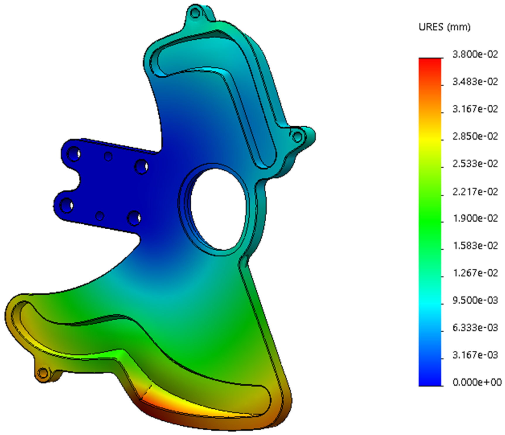
Figure 18 shows that the maximum stress experienced by the guide plate is ~150 MPa. Thus, using steel E360 material ( 360 MPa) provides a decent factor of safety (2.4). Furthermore, the maximum deformation of the guide groove remains below 40 μm (Figure 19), which is tolerable by the bearing at the guide pin.
4.2.3. Shank Part
The portion of the shank part near the knee joint is critical from the strength perspective since there are three linkage connections (connections with the thigh part and two connecting rods) next to each other. Via an iterative procedure (involving design modification and stress analysis), the design of the shank part is developed such that it can handle the stresses involved.
The shank part is most stressed at the highest knee torque demand scenario when connecting rod 1 pushes the shank with a force of 2.3 kN and connecting rod 2 pulls with the force of 0.9 kN (as per Figure 15). Another scenario where the shank is significantly stressed is when the torque demand is moderate, but, to match the demand, both cylinders apply a pushing force. From Equation (4), it can be understood how the difference in the two high forces scaled by the transmission ratios can match a desired low torque.
Figure 20 shows the chosen design of the shank where the stresses remain below 75 MPa for both extreme scenarios, and, thus, using aluminum AW 5083 material (193 MPa) allows a good factor of safety (2.6).
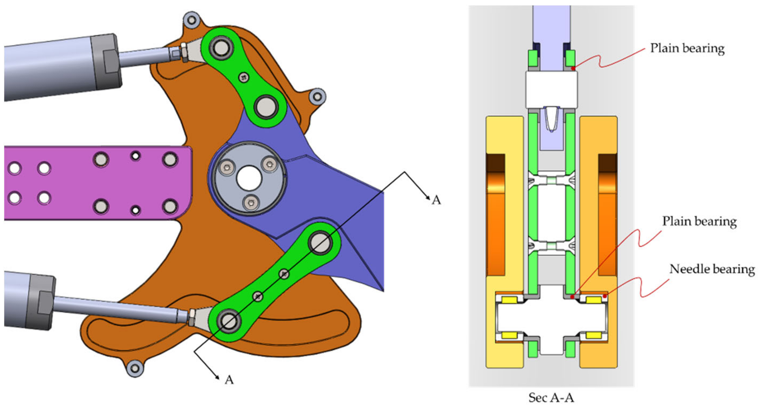
4.2.4. Bearings
At all the joints, plain bearings from Igus [40] are used. These bearings are made of special material Iglidur and are known for being extremely wear-resistant, robust, and self-lubricating [41]. With the compressive strength of 100 MPa, the bearings of appropriate dimensions manufactured from this material are able to sustain the loads experienced in the normal operation of the device.
Finally, at the guide pin, to allow the pin to move in the guide curve with little friction, needle bearings are used. Figure 21 shows the sectioned view of the design to reveal the bearings used.
4.3. Valves
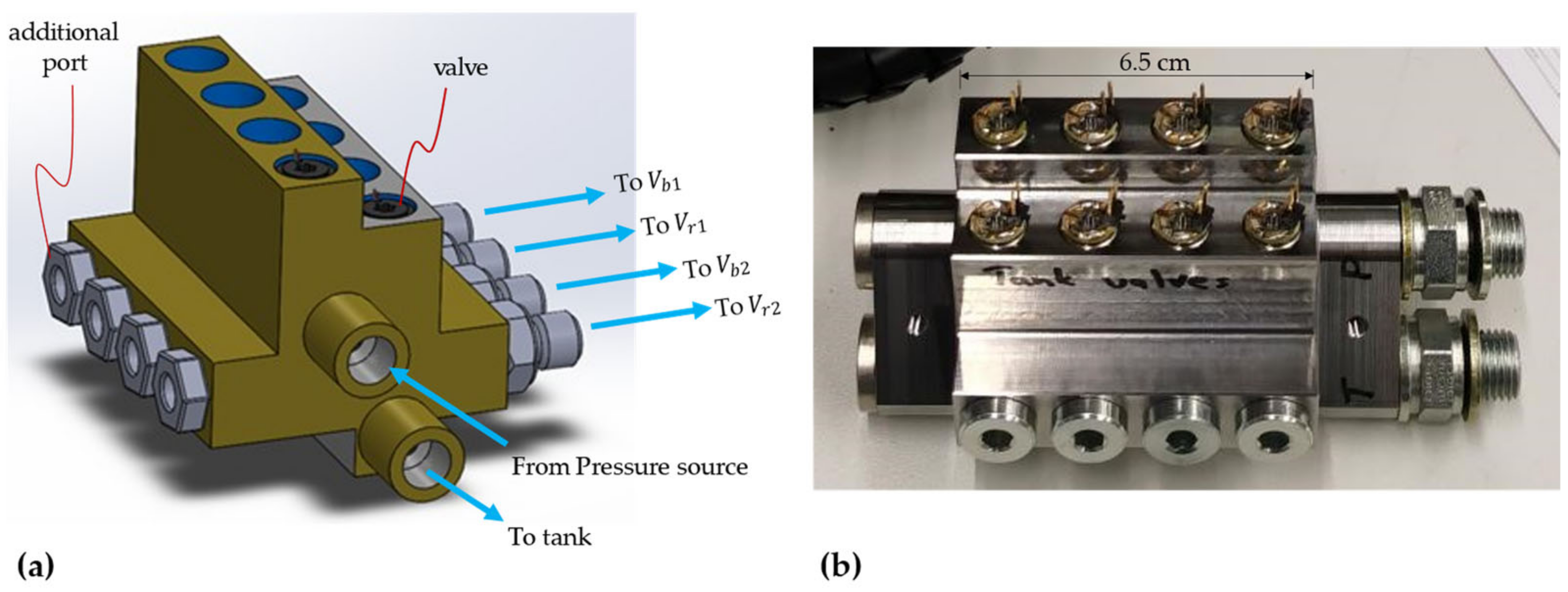
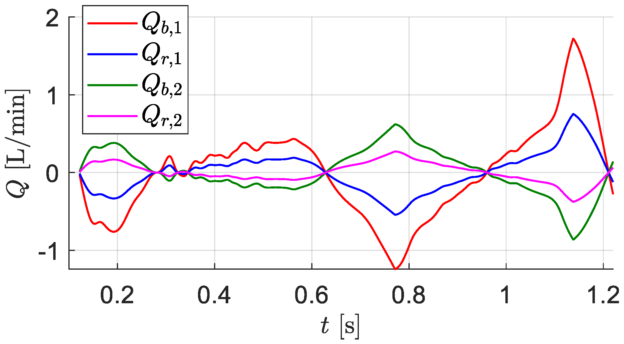
The miniature 2/2-way valves were obtained from researchers at Tampere University, Finland [42]. The eight valves are assembled in a compact fashion in a uniquely designed valve manifold, as shown in Figure 22. The flow capacity of each valve is 1.2 L/min at the pressure drop of 35 bar. The flows in the hydraulic drive during actuation of the gait cycle remain below 0.5 L/min except for one hydraulic line (connecting to the bore chamber of cylinder 1) in the swing phase, as shown in Figure 23, which goes up to 1.75 L/min. Thus, it is arguable that the pressure drop in this valve is too high for efficient operation and a larger valve would be preferable. However, this valve offers a key advantage of compactness, and such compact valves cannot be found elsewhere in the market.
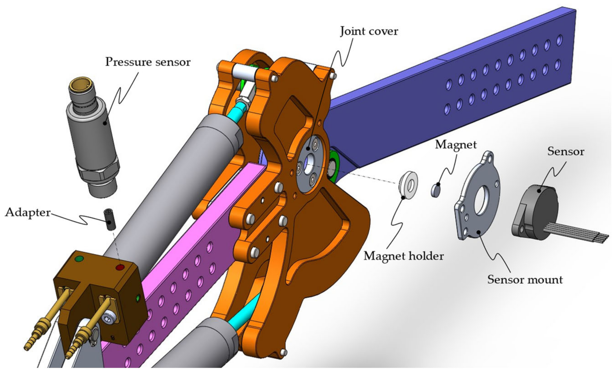
4.4. Sensors
For the control strategy described later in Section 5, the only information needed from the exoskeleton device is the knee angle. Thus, an angle sensor is integrated into the exoskeleton device. The hall effect sensor (model ETx25K) from Megatron is chosen due to its compact size [43]. The sensor’s accuracy of is adequate for the controller’s operation.
Figure 24 shows the integration of this sensor in the device. A magnet holder is fabricated out of a plastic material that has a circular groove for the sensor magnet. The magnet is inserted into this groove and then the holder with the magnet is press-fitted into the joint cover (which rotates with the shank). Next, a sensor holder is fabricated and mounted to the guide plate. Finally, the sensor is mounted on the sensor holder. This arrangement ensures a precise distance between the magnet and the sensor, which is important for sensor’s proper functionality.
5. Exoskeleton Control Strategy
Control of an exoskeleton device depends on the functional requirements of the device. In this work, the authors consider the use case of patients suffering from paraplegia where they are unable to control their leg. Thus, the exoskeleton controller makes all the decisions in a gait cycle without any input from the user. The controller is tasked with following the characteristics of a typical gait cycle (i.e., track the knee angle observed in a typical gait cycle) and providing the necessary torque at the knee.
Two different strategies have been proposed by the authors for different phases in the gait cycle, a brief description of which is presented in the following subsections (a detailed description can be found in [34]).
5.1. Passive Control in the Stance Phase
From the typical knee motion characteristics in a gait cycle (Figure 4), it can be observed that the stance phase involves an inverse linear relationship between knee angle and knee torque. That is, as the knee angle decreases, the knee torque increases and vice versa. Thus, the knee motion in the stance phase can be realized via an elastic element in the knee joint. For the hydraulically driven knee exoskeleton proposed by the authors, the compressibility of the hydraulic oil can be exploited to achieve this elastic behavior.
As shown in Figure 25, during knee flexion, cylinder chambers and reduce in size. Thus, in the stance phase, both valves connecting to each of these chambers are turned off. As a result, when the knee flexes at the beginning of the stance phase, the hydraulic oil in these chambers becomes compressed. Consequently, the pressure in the chambers rises, resulting in an increase in the torque delivered by the drive. The opposite occurs in the knee extension at the latter part of the stance phase.
To ensure that the pressure in the cylinder chambers remains below their rated pressure (200 bar) in this elastic operation, extra volumes ( and ) are added to the isolated cylinder chambers.
The size of these volumes can be determined via simple analysis, starting from the pressure build up equation for a closed volume (consisting of the cylinder chamber of area and length , and the extra volume ):
Here, is the bulk modulus of the fluid. Integrating the equation from the beginning of the elastic phase (instant a) to the middle of the elastic phase (instant b) and simplifying, the following expression for is obtained:
From the design of the mechanism, the piston positions (, ) in the cylinder at different knee angles are known. Further, the mechanism is designed so that the cylinder pressure of 200 bar can supply the necessary peak torque in the stance phase. Thus, from instant a to b, the pressure should rise from 0 bar to 200 bar, i.e., in Equation (15), bar. For a hydraulic fluid with bulk modulus of 14,000 bar, the sizes of these volumes are determined to be 85 mL and 19 mL. However, the presence of air in the fluid may lower the size requirements of these volumes. In the prototype, the valve block has additional ports (Figure 22), where these volumes of variable sizes (realized via appropriate fittings) can be mounted.
5.2. Model Predictive Control in the Swing Phase
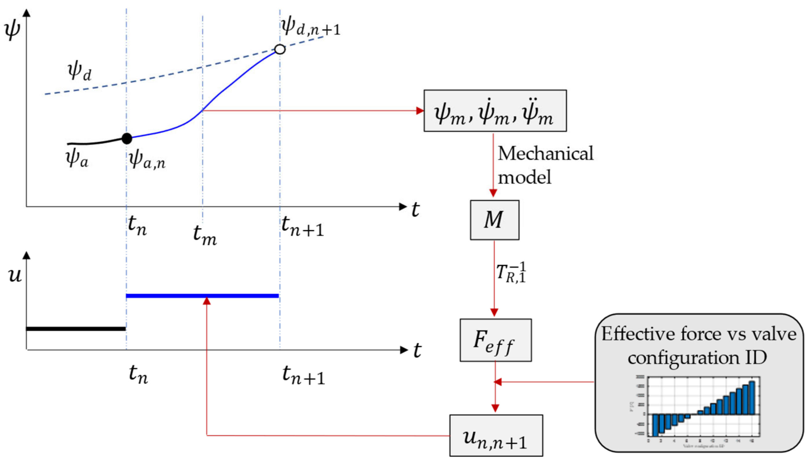
In the swing phase, the exoskeleton device needs to track a desired knee motion typical of a gait cycle. To achieve this, a simplified form of model predictive control is employed.
The control strategy is presented concisely in Figure 26. At time step , the controller uses the information of the current actual knee angle () and the desired knee angle at the next time step () to come up with a path (described by a 3rd order polynomial curve) to connect the current trajectory and the desired trajectory. This path is shown in blue in the figure. For this path, the knee angular position, velocity, and acceleration at the mid time () are determined. This information is used in the mechanical model of limb motion (Appendix A) to determine the required knee torque. Next, from the transmission ratio information, the effective force requirement from the hydraulic drive is determined. Finally, a valve configuration (out of 16) is chosen that corresponds to the nearest digital force deliverable from the drive. This valve configuration is commanded by the controller at the current time step.
6. Experimental Tests
Testing of novel exoskeleton devices is typically carried out in two phases. The first phase involves testing the operation of the exoskeleton without human in the loop. This phase is important for safety purposes. Once the motion of the exoskeleton device is found to be satisfactory and safe, then the second phase of testing is conducted with human wearing the exoskeleton device.
In this work, first-phase tests are conducted. The details of the experimental setup and test results are presented in the following subsections.
6.1. Experimental Setup
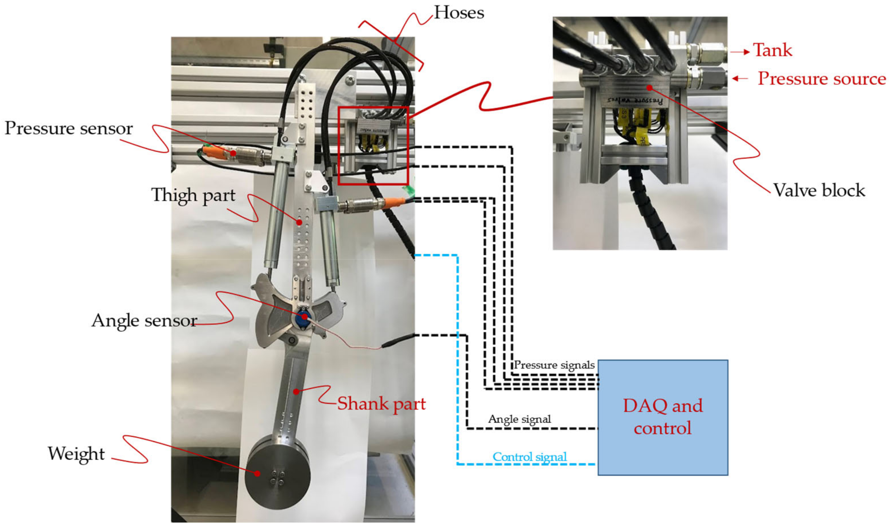
The exoskeleton prototype is mounted on a test rig, as shown in Figure 27. Two weights (1 kg each) are added on each side of the shank part to partially simulate the weight of the shank and foot of the wearer. The angle sensor attached to the knee joint measures the knee angle and transmits it to the data acquisition and control system. As described in Section 5.2, the measured knee angle is used in the motion control strategy. The pressure sensors are also present in the test setup for monitoring purposes. The details of the sensors used in the test setup are reported in Table 4.
The hydraulic power supply used in this work is a traditional supply system available to the authors that is capable of supplying flow at a preset pressure level. For an exoskeleton device that would eventually be worn by a user, the hydraulic power supply will comprise a miniature pressure-controlled electrohydraulic pump that could fit in the backpack of the user. Focus on this aspect of hydraulic power supply will be a task for the future.
Since the weights attached to the shank part are 2/5th of the typical weight of the shank and foot [35], the supply pressure is also set to 2/5th of the design pressure, i.e., 80 bar.
For data acquisition and control, a B&R X20 PLC system [45] is chosen. The system is flexible and can easily be adapted for any given I/O configuration, e.g., analog signals from the pressure sensors, bus connections, and driving the digital valves via “boost and hold” command [42].
The controller model described in Section 5.2 is implemented in MATLAB/Simulink environment. The Simulink model is then imported into the programming tool “Automation Studio” from B&R using “Automation Studio Target for Simulink” software (which allows automatic code generation from the Simulink model). Finally, “Automation Studio” establishes a TCP/IP connection with the B&R target system.
During tests, the measurements are recorded with a sampling time of 0.5 milliseconds, and postprocessing is completed in the MATLAB environment.
6.2. Test Trajectory
The goal of the tests in this work is to validate the motion control strategy proposed by the authors for the swing phase (Section 5.2) and the capability of the exoskeleton device to follow the desired motion. As shown in Figure 28a, the knee angle trajectory in the swing phase can be approximated via a cosine curve. The equation describing this curve is:
This cosine curve is repeated to generate a test trajectory (Figure 28b), which is then used in the experiments.
6.3. Test Results
The experiments are conducted on the test setup using the control strategy described in Section 5.2. The only difference is the mechanical model, which, for the case of the test setup, is:
where is the moment of inertia of the weights around the knee joint, is the torque delivered by the hydraulic drive, is the mass of the weights, is the acceleration due to gravity, and is the distance of the center of mass of the weights from the knee joint. Here, the inertia of the shank part is neglected since it is much lighter (~8 times) compared to the weights.
The exoskeleton device is asked to follow the test trajectory detailed in Section 6.2. The controller time step is set to 50 milliseconds.
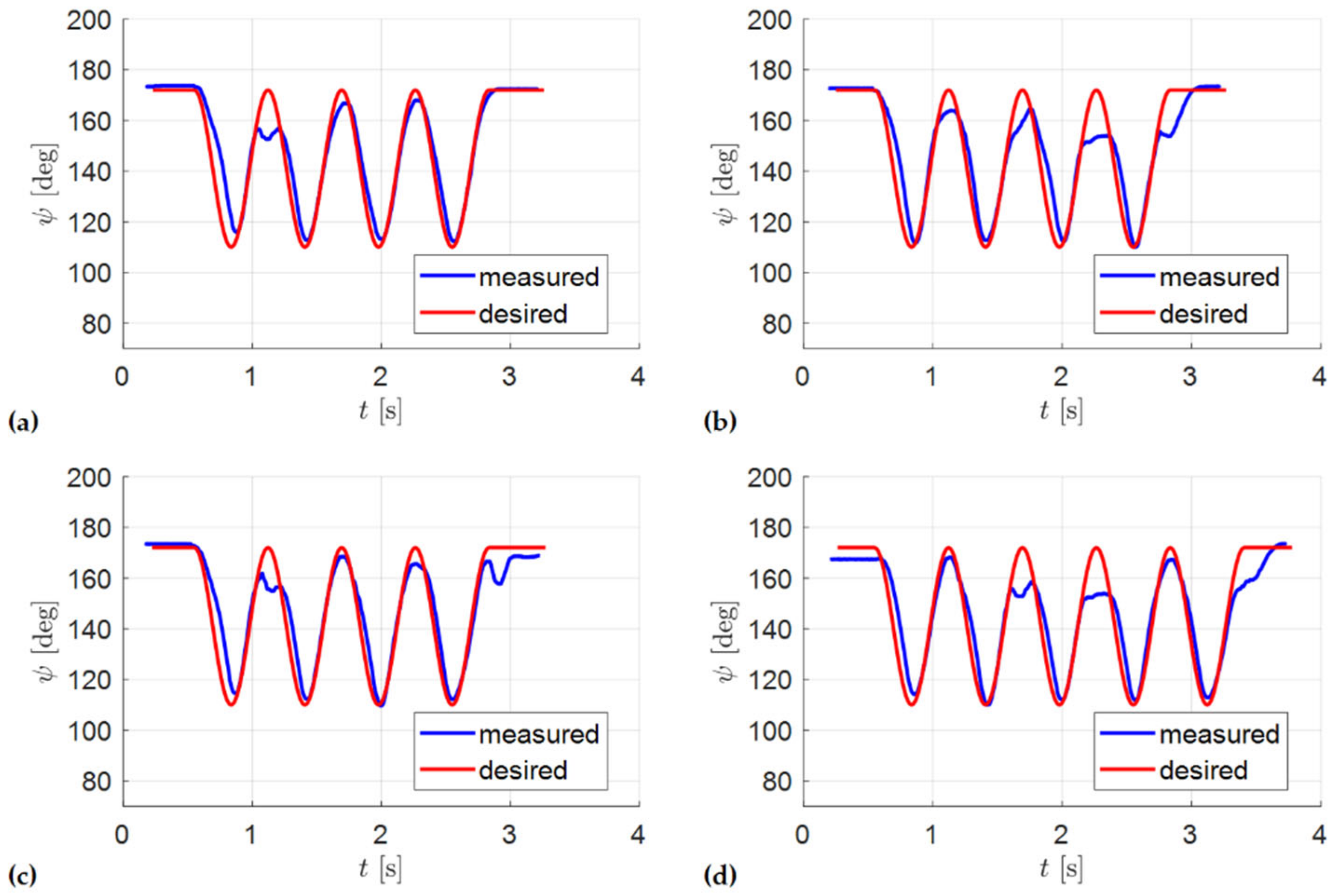
Figure 29 shows the results from four sets of experiments. The conditions for the experiments are identical except for the initial knee angle and the pressure level of the source, which varies slightly between the experiments. The results indicate that the exoskeleton device is able to track the desired trajectory reasonably well. However, at some instances, it fails to reach the full knee extension as desired.
For a quantitative analysis of the results, the error between the measured trajectory and desired trajectory is defined as:
The mean error (), its standard deviation (), and maximum error () for the four sets of measurements are reported in Table 5. The error statistics are very similar across the experiments. Mean error of is deemed to be tolerable by the user. However, the maximum error of is of concern, which is caused by the inability of the device to reach full extension for some instances.
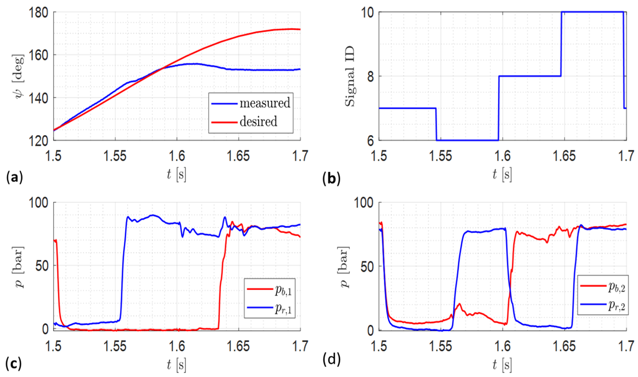
A closer investigation into this discrepancy is illustrated via Figure 30. At s, the controller commands the valve configuration of . As per Table 3, the state of the cylinder chambers should be: . However, as per Figure 30c, chamber starts to pressurize only at s. Thus, for ms, the state of the chambers is , which corresponds to . Consequently, as per Figure 12, instead of negligible force (), the drive delivers very high negative force, resulting in a sharp deceleration of the knee angle and a deviation from the desired trajectory.
The delayed pressurization of chamber is explained via the following arguments. During knee extension, chamber expands quickly. As gravity is helping the extension, the force needed from the drive is negative. From Figure 12, the valve configuration will remain below 7, i.e., chamber remains connected to the tank. Thus, is a fast-expanding chamber connected to tank, which needs high flow from the tank so that the chamber pressure can remain close to the tank pressure. However, the smallness of the valve (described in Section 4.3) restricts the amount of flow from the tank to the chamber. Consequently, the chamber pressure goes sub-atmospheric. Due the typical presence of entrained air in the fluid, its bulk modulus falls severely at such low pressures. Thus, when the chamber is connected to the pressure source, it takes more time to pressurize.
It is notable that this discrepancy in trajectory tracking only occurs in a specific situation near the end of knee extension when the controller commands a valve configuration that requires pressurized . At different instances, when the controller commands other valve configurations that do not require pressurization of this chamber, the discrepancy does not appear.
This issue can be addressed by using a larger valve that allows high enough flow to ensure that the pressure in chamber does not fall below the atmospheric pressure. However, the availability of larger valves in a compact arrangement remains a challenge, and, thus, other alternatives are needed to be investigated in the future.
7. Discussion
The digital hydraulically driven knee exoskeleton developed and tested in this work presents a significant advancement in terms of using hydraulics technology for actuation of exoskeleton devices. Compared to the traditional hydraulics technology used by past exoskeletons [8,12,14,15,18], the digital hydraulically driven exoskeleton device promises higher compactness, efficiency, and robustness. The compactness is illustrated in this work via the size of the valve block containing eight 2/2-way valves. Since the operations performed by the device in this work and the past devices in the literature are different, a direct efficiency comparison is not possible at this stage. However, the next phase of full gait cycle testing with user-in-loop will allow this direct efficiency comparison.
Another key advantage of the exoskeleton device presented in this work is that, since it is designed for paraplegic patients, it is capable of supplying 100% of the torque requirement at the knee joint. In contrast, most of the past works on exoskeleton development deal with partial disability or power augmentation. Thus, the devices developed are capable of supplying only up to 30% to 50% of the knee torque [15,23].
Since paraplegic patients are unable to control their leg, the controller of the exoskeleton device developed in this work makes all the decisions in the gait cycle. A simplified model predictive controller is proven (in this work and authors’ past works [34]) to be sufficient for this task. In contrast, the devices developed for patients with partial disability and for power augmentation should account for the interaction between the force supplied by the human and the device. Thus, researchers working on such devices have used a variety of complex control strategies, ranging from cascade force control [14] to joint torque control [15] and repetitive learning control [16].
In the future, the authors would also like to extend the use case of their exoskeleton device to patients who can partially control their knee. A key challenge in this regard is identification of the motion intent of the wearer. Several approaches for motion intent identification have been proposed by other researchers [46]; however, one compatible with the drive system used in this work needs to be investigated.
The final discussion point is that of the prototype weight. The first-generation prototype developed in this work has been observed to be too heavy for users’ comfort (2.8 kg). In contrast, Sun et al.’s LEHA weighs 2.5 kg (including the power supply) [29]. The reason behind this high weight (despite the optimized design) primarily lies in the twin-tube cylinder design. Such a design unnecessarily increases the amount of material used, thus increasing the weight (the cylinders weigh 0.62 kg and 0.54 kg, respectively). However, this is an obvious limitation of using off-the-shelf components. Sun et al. were able to achieve a low weight of their device by custom-designing the components. In the future, the prospects of inhouse manufacturing of cylinders will also be explored by the authors, which could address the weight issue and also enable an area ratio of 4:1, which is ideal for uniform force stepping of the digital drive. Furthermore, the simplicity of the guide plate design results in its high weight (0.4 kg each). In the next generation of the prototype, the guide plate design could be further optimized by developing a truss-frame-type structure, which will significantly lower its weight.
8. Conclusions
This article presents development and first-phase testing of a novel digital hydraulically driven knee exoskeleton prototype, the idea of which was conceived by the authors in their previous works. Via a multi-objective optimization study, a design is developed that is optimal with respect to its size and weight. The designs of the linkage parts are further refined while ensuring that each part can safely support the load exerted on it over a typical operational cycle. Subsequently, the prototype is manufactured and assembled with procured hydraulic cylinders, valves, and sensors. Finally, first-phase testing (without human) is conducted, where the prototype is mounted on a test stand and the controller is tasked with following a given trajectory that resembles the swing motion in a typical gait cycle. The results indicate that the prototype is able to track the desired motion, except with occasional discrepancies at full knee extension.
In the future, investigations to address the aforementioned discrepancy need to be conducted. These should be followed by testing the full gait cycle operation with a human in the loop.
Overall, the novel digital hydraulically driven knee exoskeleton device prototyped and tested in this work is a significant step towards bringing the advantages of digital hydraulics technology to the field of hydraulically driven exoskeleton devices. This can pave the way for widespread adoption of power-dense hydraulics technology in actuation of exoskeletons. The resulting compact lightweight exoskeleton devices will ultimately improve the comfort level of the wearers.
Furthermore, this work also showcases the gaps in the current hydraulics components’ availability (e.g., miniature yet efficient valves and lightweight cylinders), which has historically hindered usage of hydraulics technology in exoskeleton actuation. This can be interpreted as an exciting opportunity for the industry and the research community for further research and development in this regard.
Author Contributions
Conceptualization, R.R., R.S. and P.L.; methodology, R.R., M.L. and A.P.; software, R.R. and A.P.; validation, R.R.; formal analysis, R.R., R.S. and M.L.; investigation, R.R.; resources, R.S. and P.L.; data curation, R.R.; writing—original draft preparation, R.R.; writing—review and editing, R.R. and R.S.; visualization, R.R. and M.L.; supervision, R.S. and P.L.; project administration, R.S. and P.L.; funding acquisition, R.S. All authors have read and agreed to the published version of the manuscript.
Funding
This work was completed in the framework of the COMET K2 Center on Symbiotic Mechatronics, which is funded by the Austrian Federal Government, the State Upper Austria, and by its Scientific and Industrial Partners.
Data Availability Statement
Not applicable.
Acknowledgments
Open Access Funding by the University of Linz. The authors thank Miika Paloniitty and Matti Linjama from Tampere University for providing the miniature hydraulic valves for this research work.
Conflicts of Interest
The authors declare no conflict of interest. The funders had no role in the design of the study; in the collection, analyses, or interpretation of data; in the writing of the manuscript; or in the decision to publish the results.
Nomenclature
| Area | |
| Guide curve | |
| Force | |
| Acceleration due to gravity | |
| Moment of inertia | |
| Bulk modulus of the fluid | |
| Kinetic energy of the system | |
| Length of the connecting rod | |
| Knee torque | |
| Mass | |
| P | Pressure source |
| Potential energy | |
| Flow rate | |
| Contact force at the guide curve | |
| Crank length | |
| T | Tank |
| Time | |
| Transmission ratio | |
| Valve configuration | |
| V | Volume |
| v | Valve |
| W | Work |
| w | Lateral width of the exoskeleton device |
| x, y | Coordinate positions |
| z | Piston position in the cylinder |
| Greek letters | |
| α | Angle between the connecting rod and the tangent to the guide curve |
| γ | Angle between the hydraulic cylinder rod and the tangent to the guide curve |
| Angle between the crank and the shank | |
| Yield strength | |
| Angular position of limb part | |
| Knee angle | |
| Subscripts | |
| 1,2 | Mechanism identifier |
| Actual | |
| Bore side of hydraulic cylinder | |
| Connecting rod | |
| Desired | |
| Friction | |
| Middle | |
| Measured | |
| Time step | |
| Rod side of hydraulic cylinder | |
| Source | |
| Abbreviations | |
| Effective | |
| Hydraulic |
Appendix A. Mechanical Model of Lower Limb Motion
The mechanical model of limb motion has been presented by the authors in previous works [33,34]. However, for the sake of completeness, the authors recapitulate the model in this appendix.
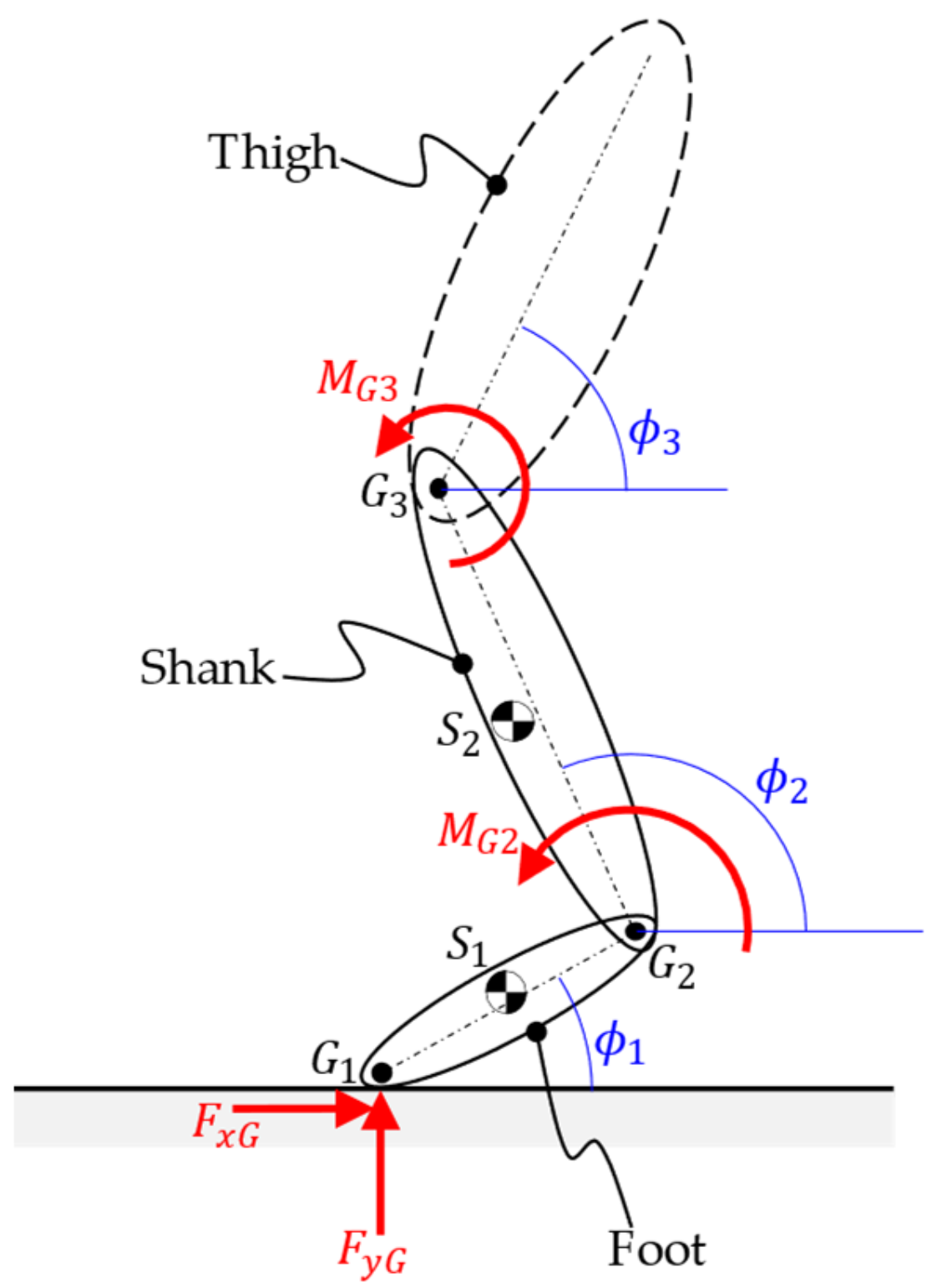
The lower limb motion is modelled via a planar system comprising foot, shank, and thigh. The motion of the upper body is until the thigh is considered to be known from the HuMoD database. Thus, the knee and ankle joint motions are the DOFs (degrees of freedom) considered in the model.
Figure A1.
Planar view of limb with variables present in the mechanical model.

The kinetic and potential energy of the system is expressible as:
where is the mass, is the position of the center of mass, is the moment of inertia, is the angular position of the limb part, and is the unit vector in vertical direction.
Next, the virtual work due to torques at the joints () and the ground reaction force () is:
Substituting these expressions into the Lagrange equation of motion and simplifying, the following expression for the knee torque is obtained:
where and are the effective masses of foot and shank, is the ground reaction term, and contains the terms related to the centripetal force, gravity, and the force from thigh. The complete expressions are lengthy, and, hence, are not shown here.
References
- Li, S.; Francisco, G.E.; Zhou, P. Post-stroke hemiplegic gait: New perspective and insights. Front. Physiol. 2018, 9, 1021. [Google Scholar] [CrossRef] [PubMed] [Green Version]
- Nilsson, A.; Vreede, K.S.; Häglund, V.; Kawamoto, H.; Sankai, Y.; Borg, J. Gait training early after stroke with a new exoskeleton—The hybrid assistive limb: A study of safety and feasibility. J. NeuroEng. Rehabil. 2014, 11, 92. [Google Scholar] [CrossRef] [PubMed] [Green Version]
- Voilqué, A.; Masood, J.; Fauroux, J.C.; Sabourin, L.; Guezet, O. Industrial Exoskeleton Technology: Classification, Structural Analysis, and Structural Complexity Indicator. In Proceedings of the 2019 Wearable Robotics Association Conference (WearRAcon), Scottsdale, AZ, USA, 25–27 March 2019; pp. 13–20. [Google Scholar]
- Proud, J.K.; Lai, D.T.H.; Mudie, K.L.; Carstairs, G.L.; Billing, D.C.; Garofolini, A.; Begg, R.K. Exoskeleton application to military manual handling tasks. Hum. Factors 2022, 64, 527–554. [Google Scholar] [CrossRef] [PubMed]
- Osipov, A. Fire exoskeleton to facilitate the work of the fireman. E3S Web. Conf. 2019, 126, 00015. [Google Scholar] [CrossRef]
- De la Tejera, J.A.; Bustamante-Bello, R.; Ramirez-Mendoza, R.A.; Izquierdo-Reyes, J. Systematic review of exoskeletons towards a general categorization model proposal. Appl. Sci. 2021, 11, 76. [Google Scholar] [CrossRef]
- Scheidl, R. Digital Fluid Power for Exoskeleton Actuation—Guidelines, Opportunities, Challenges. In Proceedings of the Ninth Workshop on Digital Fluid Power, Aalborg, Denmark, 7–8 September 2017. [Google Scholar]
- Zoss, A.; Kazerooni, H.; Chu, A. On the Mechanical Design of the Berkeley Lower Extremity Exoskeleton (BLEEX). In Proceedings of the 2005 IEEE/RSJ International Conference on Intelligent Robots and Systems, Edmonton, AB, Canada, 2–6 August 2005; pp. 3465–3472. [Google Scholar]
- Zoss, A.B.; Kazerooni, H.; Chu, A. Biomechanical design of the Berkeley Lower Extremity Exoskeleton (BLEEX). IEEE/ASME Trans. Mechatron. 2006, 11, 128–138. [Google Scholar] [CrossRef]
- Kazerooni, H.; Racine, J.-L.; Huang, L.; Steger, R. On the Control of the Berkeley Lower Extremity Exoskeleton (BLEEX). In Proceedings of the 2005 IEEE International Conference on Robotics and Automation, Barcelona, Spain, 18–22 April 2005; pp. 4353–4360. [Google Scholar]
- Xie, H.; Li, X.; Li, W.; Li, X. The Proceeding of the Research on Human Exoskeleton. In Advances in Intelligent Systems Research; Atlantis Press: Amsterdam, The Netherlands, 2014; pp. 754–758. [Google Scholar]
- Karlin, S. Raiding Iron Man’s Closet [Geek Life]. IEEE Spectr. 2011, 48, 25. [Google Scholar] [CrossRef] [Green Version]
- Huo, W.; Mohammed, S.; Moreno, J.C.; Amirat, Y. Lower limb wearable robots for assistance and rehabilitation: A state of the art. IEEE Syst. J. 2016, 10, 1068–1081. [Google Scholar] [CrossRef]
- Chen, S.; Chen, Z.; Yao, B.; Zhu, X.; Zhu, S.; Wang, Q.; Song, Y. Adaptive robust cascade force control of 1-DOF hydraulic exoskeleton for human performance augmentation. IEEE/ASME Trans. Mechatron. 2017, 22, 589–600. [Google Scholar] [CrossRef]
- Kim, H.; Shin, Y.J.; Kim, J. Design and locomotion control of a hydraulic lower extremity exoskeleton for mobility augmentation. Mechatronics 2017, 46, 32–45. [Google Scholar] [CrossRef]
- Yang, Y.; Dong, X.; Liu, X.; Huang, D. Robust repetitive learning-based trajectory tracking control for a leg exoskeleton driven by hybrid hydraulic system. IEEE Access 2020, 8, 27705–27714. [Google Scholar] [CrossRef]
- Chen, S.; Han, T.; Dong, F.; Lu, L.; Liu, H.; Tian, X.; Han, J. Precision interaction force control of an underactuated hydraulic stance leg exoskeleton considering the constraint from the wearer. Machines 2021, 9, 96. [Google Scholar] [CrossRef]
- Ouyang, X.; Ding, S.; Fan, B.; Li, P.Y.; Yang, H. Development of a novel compact hydraulic power unit for the exoskeleton robot. Mechatronics 2016, 38, 68–75. [Google Scholar] [CrossRef]
- Kosaki, T.; Li, S. A water-hydraulic upper-limb assistive exoskeleton system with displacement estimation. J. Robot. Mechatron. 2020, 30, 149–156. [Google Scholar] [CrossRef]
- Kaminaga, H.; Ono, J.; Nakashima, Y.; Nakamura, Y. Development of Backdrivable Hydraulic Joint Mechanism for Knee Joint of Humanoid Robots. In Proceedings of the 2009 IEEE International Conference on Robotics and Automation, Kobe, Japan, 12–17 May 2009; pp. 1577–1582. [Google Scholar]
- Kaminaga, H.; Amari, T.; Niwa, Y.; Nakamura, Y. Electro-Hydrostatic Actuators with Series Dissipative Property and Their Application to Power Assist Devices. In Proceedings of the 2010 3rd IEEE RAS & EMBS International Conference on Biomedical Robotics and Biomechatronics, Tokyo, Japan, 26–29 September 2010; pp. 76–81. [Google Scholar]
- Kaminaga, H.; Tanaka, H.; Nakamura, Y. Mechanism and Control of Knee Power Augmenting Device with Backdrivable Electro-Hydrostatic Actuator. In Proceedings of the 13th World Congress in Mechanism and Machine Science, Guanajuato, Mexico, 19–23 June 2011. [Google Scholar]
- Kaminaga, H.; Amari, T.; Niwa, Y.; Nakamura, Y. Development of Knee Power Assist Using Backdrivable Electro-Hydrostatic Actuator. In Proceedings of the 2010 IEEE/RSJ International Conference on Intelligent Robots and Systems, Taipei, Taiwan, 18–22 October 2010; pp. 5517–5524. [Google Scholar]
- Tanaka, H.; Kaminaga, H.; Nakamura, Y. Pressure feedback control based on singular perturbation method of an electro-hydrostatic actuator for an exoskeletal power-assist system. J. Robot. Mechatron. 2012, 24, 354–362. [Google Scholar] [CrossRef]
- Kurosawa, H.; Walker, P.S.; Abe, S.; Garg, A.; Hunter, T. Geometry and motion of the knee for implant and orthotic design. J. Biomech. 1985, 18, 487–499. [Google Scholar] [CrossRef]
- Lee, D.; Song, B.; Park, S.Y.; Baek, Y.S. Development and control of an electro-hydraulic actuator system for an exoskeleton robot. Appl. Sci. 2019, 9, 4295. [Google Scholar] [CrossRef] [Green Version]
- Jiang, J.; Wang, Y.; Cao, H.; Zhu, J.; Zhang, X. A novel pump-valve coordinated controlled hydraulic system for the lower extremity exoskeleton. Trans. Inst. Meas. Control 2020, 42, 2872–2884. [Google Scholar] [CrossRef]
- Lee, T.; Lee, D.; Song, B.; Baek, Y.S. Design and control of a polycentric knee exoskeleton using an electro-hydraulic actuator. Sensors 2020, 20, 211. [Google Scholar] [CrossRef] [Green Version]
- Sun, M.; Ouyang, X.; Mattila, J.; Chen, Z.; Yang, H.; Liu, H. Lightweight electrohydrostatic actuator drive solution for exoskeleton robots. IEEE/ASME Trans. Mechatron. 2022, 1–12. [Google Scholar] [CrossRef]
- Scheidl, R.; Linjama, M.; Schmidt, S. Is the future of fluid power digital? Proc. Inst. Mech. Eng. Part I J. Syst. Control. Eng. 2012, 226, 721–723. [Google Scholar] [CrossRef]
- Cao, H.; Ling, Z.; Zhu, J.; Wang, Y.; Wang, W. Design Frame of a Leg Exoskeleton for Load-Carrying Augmentation. In Proceedings of the 2009 IEEE International Conference on Robotics and Biomimetics (ROBIO), Guangxi, China, 13–19 December 2009; pp. 426–431. [Google Scholar]
- Holl, E.; Scheidl, R.; Eshkabilov, S. Simulation Study of a Digital Hydraulic Drive for a Knee Joint Exoskeleton. In Proceedings of the ASME/BATH 2017 Symposium on Fluid Power and Motion Control, Sarasota, FL, USA, 4 December 2017. [Google Scholar]
- Rituraj, R.; Scheidl, R.; Ladner, P.; Lauber, M. A Novel Design Concept of Digital Hydraulic Drive for Knee Exoskeleton. In Proceedings of the ASME/BATH 2021 Symposium on Fluid Power and Motion Control, Virtual, 13 December 2021. [Google Scholar]
- Rituraj, R.; Scheidl, R. Advancements in the Control Strategy for Digital Hydraulically Driven Knee Exoskeleton. In Proceedings of the ASME/BATH 2022 Symposium on Fluid Power and Motion Control, Bath, UK, 19 September 2022. [Google Scholar]
- HuMoD. Available online: https://www.sim.informatik.tu-darmstadt.de/res/ds/humod/ (accessed on 30 March 2022).
- Wojtusch, J.; Von Stryk, O. HuMoD—A Versatile and Open Database for the Investigation, Modeling and Simulation of Human Motion Dynamics on Actuation Level. In Proceedings of the 2015 IEEE-RAS 15th International Conference on Humanoid Robots (Humanoids), Seoul, Republic of Korea, 3–5 November 2015; pp. 74–79. [Google Scholar]
- Deb, K.; Pratap, A.; Agarwal, S.; Meyarivan, T. A fast and elitist multiobjective genetic algorithm: NSGA-II. IEEE Trans. Evol. Comput. 2002, 6, 182–197. [Google Scholar] [CrossRef] [Green Version]
- HAWE Micro Fluid GmbH. Available online: www.hawe.com (accessed on 22 February 2022).
- SOLIDWORKS Simulation. Available online: https://www.solidworks.com/domain/simulation (accessed on 1 June 2022).
- Igus. Available online: https://www.igus.co.uk/ (accessed on 3 July 2022).
- Iglidur. Available online: https://www.igus.co.uk/info/plain-bearings-x-material-data (accessed on 3 July 2022).
- Linjama, M.; Paloniitty, M.; Tiainen, L.; Huhtala, K. Mechatronic design of digital hydraulic micro valve package. Procedia Eng. 2015, 106, 97–107. [Google Scholar] [CrossRef]
- Megatron Kit Encoder Etx25K. Available online: https://www.megatron.de/en/products/angle-sensors/encoder-etx25k-with-3d-hall-as-kit-versions.html (accessed on 30 July 2022).
- Autosen AP019 Pressure Sensor. Available online: https://autosen.com/en/Process-Sensors/Pressure-sensors/Electronic-pressure-sensor-G1-4M-AP019 (accessed on 7 August 2022).
- B&R X20 System. Available online: https://www.br-automation.com/en/products/plc-systems/x20-system/ (accessed on 7 August 2022).
- Yang, J.; He, Y.; Shi, P.; Yu, H. A review on human intent understanding and compliance control strategies for lower limb exoskeletons. Proc. Inst. Mech. Eng. Part I J. Syst. Control. Eng. 2022, 236, 1067–1086. [Google Scholar] [CrossRef]
Figure 1.
Knee exoskeleton attached to the human leg (left); details of the exoskeleton design and the digital hydraulic drive (right).
Figure 1.
Knee exoskeleton attached to the human leg (left); details of the exoskeleton design and the digital hydraulic drive (right).

Figure 2.
Valve positions for 16 unique valve configurations.

Figure 3.
Illustration of the piston positions (), knee angle (), cylinder forces ), and knee torque ().
Figure 3.
Illustration of the piston positions (), knee angle (), cylinder forces ), and knee torque ().

Figure 4.
(a) Knee angle and torque over one gait cycle; (b) knee torque vs. knee angle over multiple gait cycles; (c) knee torque vs. knee angular speed over multiple gait cycles.
Figure 4.
(a) Knee angle and torque over one gait cycle; (b) knee torque vs. knee angle over multiple gait cycles; (c) knee torque vs. knee angular speed over multiple gait cycles.

Figure 5.
Transmission ratios of the two mechanisms.

Figure 6.
Effective force delivered by the hydraulic drive for different valve configurations.

Figure 7.
Illustration of critical geometrical dimensions used in the optimization problem. Inset shows the angles formed by the cylinder rod and connecting rod with the tangent of the guide curve at the guide pin.
Figure 7.
Illustration of critical geometrical dimensions used in the optimization problem. Inset shows the angles formed by the cylinder rod and connecting rod with the tangent of the guide curve at the guide pin.

Figure 8.
Force delivered by the hydraulic cylinders to support the required knee torque at different knee angles: (a) cylinder for mechanism 1; (b) cylinder for mechanism 2.
Figure 8.
Force delivered by the hydraulic cylinders to support the required knee torque at different knee angles: (a) cylinder for mechanism 1; (b) cylinder for mechanism 2.

Figure 9.
Approximate pareto-front obtained from the optimization study.

Figure 10.
Three designs from the pareto-front: (a) design A; (b) design B; (c) design C. Mechanisms 1 and 2 are shown in blue and magenta, respectively. The guide groove profiles are shown in green.
Figure 10.
Three designs from the pareto-front: (a) design A; (b) design B; (c) design C. Mechanisms 1 and 2 are shown in blue and magenta, respectively. The guide groove profiles are shown in green.

Figure 11.
Sectioned view of the hydraulic cylinder from HAWE, illustrating the twin-tube design and the internal flow channels.
Figure 11.
Sectioned view of the hydraulic cylinder from HAWE, illustrating the twin-tube design and the internal flow channels.

Figure 12.
Effective force for different valve configurations using HAWE cylinders.

Figure 13.
Illustration of the central plane and coplanarity of different linkages: (a) tilted view of the design; (b) bottom view of the design indicating the coplanarity of the thigh (magenta), cylinder (grey), and shank (blue) parts.
Figure 13.
Illustration of the central plane and coplanarity of different linkages: (a) tilted view of the design; (b) bottom view of the design indicating the coplanarity of the thigh (magenta), cylinder (grey), and shank (blue) parts.

Figure 14.
Realization of the connecting rod linkage in the prototype.

Figure 15.
Forces (positive being compressive, negative being tensile) acting on the connecting rod linkages: (a) mechanism 1; (b) mechanism 2.
Figure 15.
Forces (positive being compressive, negative being tensile) acting on the connecting rod linkages: (a) mechanism 1; (b) mechanism 2.

Figure 16.
Stress analysis of the connecting rod elements in (a) compression and (b) tension.

Figure 17.
Forces (positive being outwards, negative being inwards) acting on the grooves of the guide plates: (a) grooves for mechanism 1; (b) grooves for mechanism 2.
Figure 17.
Forces (positive being outwards, negative being inwards) acting on the grooves of the guide plates: (a) grooves for mechanism 1; (b) grooves for mechanism 2.

Figure 18.
Stress analysis of the guide plate with the contact force exerted at the location of the guide pins for the knee angle of .
Figure 18.
Stress analysis of the guide plate with the contact force exerted at the location of the guide pins for the knee angle of .

Figure 19.
Deformation of the guide plate under the forces shown in Figure 18.
Figure 19.
Deformation of the guide plate under the forces shown in Figure 18.

Figure 20.
Stress analysis of the shank part: (a) high torque transfer case; (b) high internal force case.
Figure 20.
Stress analysis of the shank part: (a) high torque transfer case; (b) high internal force case.

Figure 21.
Illustration of the bearings (plain bearings from Igus and needle bearings) used in the design.
Figure 21.
Illustration of the bearings (plain bearings from Igus and needle bearings) used in the design.

Figure 22.
Valve manifold housing eight 2/2-way valves: (a) CAD; (b) procured valve block.

Figure 23.
Flow in and out of the cylinder chambers over a gait cycle.

Figure 24.
Sensor integration into the exoskeleton design.

Figure 25.
The valve configurations to realize the elastic behavior in the stance phase.

Figure 26.
Illustration of the control strategy used in the swing phase of the gait cycle.

Figure 27.
Experimental setup showing the exoskeleton device mounted on a test rig and connections to the data acquisition (DAQ) and control system. The inset indicates the valve block and connections to the pressure source and tank.
Figure 27.
Experimental setup showing the exoskeleton device mounted on a test rig and connections to the data acquisition (DAQ) and control system. The inset indicates the valve block and connections to the pressure source and tank.

Figure 28.
(a) Knee angle and a cosine curve approximation in the swing phase; (b) the repeating cosine curve used as the test trajectory.
Figure 28.
(a) Knee angle and a cosine curve approximation in the swing phase; (b) the repeating cosine curve used as the test trajectory.

Figure 29.
Results in the form of knee angle measured and desired (from the planned trajectory) for four sets of experiments: (a) Experiment A; (b) Experiment B; (c) Experiment C; (d) Experiment D.
Figure 29.
Results in the form of knee angle measured and desired (from the planned trajectory) for four sets of experiments: (a) Experiment A; (b) Experiment B; (c) Experiment C; (d) Experiment D.

Figure 30.
(a) Zoomed view of plot from Figure 29d; (b) valve configurations commanded by the controller; (c) pressure in cylinder 1 chambers; (d) pressure in cylinder 2 chambers.
Figure 30.
(a) Zoomed view of plot from Figure 29d; (b) valve configurations commanded by the controller; (c) pressure in cylinder 1 chambers; (d) pressure in cylinder 2 chambers.


Table 1.
Lower () and upper () bounds of the design variables in the optimization problem.
| 20 | 20 | 20 | 180 | 30 | 130 | 30 | 0 | 30 | ||
| 60 | 60 | 60 | 60 | 350 | 40 | 300 | 40 | 80 | 190 |
Table 2.
Values of the design variables for the chosen design (design B).
| 38.9 | 29.6 | 48.7 | 30.2 | 281.7 | 31.3 | 210.0 | 30.0 | 55.4 | 174.2 |
Table 3.
Cylinder chamber state for different valve configurations (). and are the bore and rod side chambers of cylinder 1/2. Chamber state of 1 and 0 indicate pressurized and depressurized, respectively.
Table 3.
Cylinder chamber state for different valve configurations (). and are the bore and rod side chambers of cylinder 1/2. Chamber state of 1 and 0 indicate pressurized and depressurized, respectively.
| 1 | 2 | 3 | 4 | 5 | 6 | 7 | 8 | 9 | 10 | 11 | 12 | 13 | 14 | 15 | 16 | |
|---|---|---|---|---|---|---|---|---|---|---|---|---|---|---|---|---|
| 0 | 0 | 0 | 0 | 0 | 0 | 0 | 1 | 0 | 1 | 1 | 1 | 1 | 1 | 1 | 1 | |
| 1 | 1 | 0 | 1 | 0 | 1 | 0 | 1 | 0 | 1 | 0 | 1 | 0 | 1 | 0 | 0 | |
| 1 | 1 | 1 | 0 | 1 | 0 | 0 | 1 | 0 | 1 | 1 | 0 | 1 | 0 | 0 | 0 | |
| 0 | 1 | 0 | 0 | 1 | 1 | 0 | 0 | 1 | 1 | 0 | 0 | 1 | 1 | 0 | 1 |
Table 4.
Specification of the sensors used in the tests.
| Sensor | Model | Accuracy | Measuring Range | Resolution |
|---|---|---|---|---|
| Angle sensor | Megatron ETx25K | |||
| Pressure sensor | Autosen AP019 | bar | - |
Table 5.
Statistics for the error between the measured and desired trajectories.
| Error Statistics | (a) | (b) | (c) | (d) |
|---|---|---|---|---|
Publisher’s Note: MDPI stays neutral with regard to jurisdictional claims in published maps and institutional affiliations. |
© 2022 by the authors. Licensee MDPI, Basel, Switzerland. This article is an open access article distributed under the terms and conditions of the Creative Commons Attribution (CC BY) license (https://creativecommons.org/licenses/by/4.0/).
Share and Cite
MDPI and ACS Style
Rituraj, R.; Scheidl, R.; Ladner, P.; Lauber, M.; Plöckinger, A. Prototyping and Experimental Investigation of Digital Hydraulically Driven Knee Exoskeleton. Energies 2022, 15, 8695. https://0-doi-org.brum.beds.ac.uk/10.3390/en15228695
AMA Style
Rituraj R, Scheidl R, Ladner P, Lauber M, Plöckinger A. Prototyping and Experimental Investigation of Digital Hydraulically Driven Knee Exoskeleton. Energies. 2022; 15(22):8695. https://0-doi-org.brum.beds.ac.uk/10.3390/en15228695
Chicago/Turabian StyleRituraj, Rituraj, Rudolf Scheidl, Peter Ladner, Martin Lauber, and Andreas Plöckinger. 2022. "Prototyping and Experimental Investigation of Digital Hydraulically Driven Knee Exoskeleton" Energies 15, no. 22: 8695. https://0-doi-org.brum.beds.ac.uk/10.3390/en15228695
Note that from the first issue of 2016, this journal uses article numbers instead of page numbers. See further details here.