
Study on Stability of Gas Pressure Regulator with a Built-In Silencer
by
Dmitry Stadnik
,
Victor Sverbilov
*,
Vladimir Ilyukhin
,
Alexander Igolkin
,
Maxim Balyaba
and
Evgeniy Shakhmatov
Automatic Systems of Power Plants Department, Institute of Engine and Power Plants Engineering, Samara University, Moskovskoye Shosse 34, 443086 Samara, Russia
*
Author to whom correspondence should be addressed.
Energies 2023, 16(1), 372; https://0-doi-org.brum.beds.ac.uk/10.3390/en16010372
Submission received: 14 November 2022
/
Revised: 24 December 2022
/
Accepted: 25 December 2022
/
Published: 28 December 2022
(This article belongs to the Special Issue Application and Analysis in Fluid Power Systems)
Abstract
:Gas pressure regulators are widely used in gas transportation and distribution systems. They are designed for deep pressure reduction and maintainance with high accuracy over a wide flow range. Operation at a high pressure drop is accompanied by a high level of noise, for reduction of which, silencers are used. However, installation of a noise suppressor into the regulator design has a significant impact on its static and dynamic characteristics. This can lead to a decrease of accuracy, loss of stability and occurrence of self-oscillations of the valve. These, in turn, lead to increasing noise and vibration, wear of contact surfaces and premature failure of the regulator. The paper presents results of a study of dynamic characteristics of a modernized serial regulator with a built-in noise suppressor. A mathematical model was compiled and its study was carried out in the SimulationX software package. The joint influence on the system stability of the parameters of the muffler and the block of throttles, designed to adjust the static characteristic of the regulator, is considered. It is shown that the proper choice of throttle resistances can ensure the stability of the control system in a wide range of gas flow rates. The results can be used when designing regulators with built-in noise suppressors.
1. Introduction
To supply and distribute natural gas to industrial enterprises and settlements with the required pressure, degree of purification and odorization, gas distribution stations (GDS) and gas delivery points (GDP) are built into gas pipeline networks. Pressure-reducing valves are widely used in GDSs and GDPs as the key devices for strong reduction of gas pressure (from 7–5 MPa to 1–0.6 MPa) and to keep outlet pressure constant with high accuracy over a wide range of gas flow rates. The gas velocity under such pressure drops reaches supersonic values, which results in intensive flow and pressure ripples. In certain cases, noise levels exceed the maximum permissible values by 25–35 dB (A). Regulator operation under intense dynamic loads from the flow side is often accompanied by self-oscillation of moving elements, which leads to a further increase of noise and vibration, to a decrease of control accuracy, to excessive gas consumption and to failure of the regulator itself [1]. Thus, reducing the noise and vibration of such systems is an urgent and important task, both from an environmental and an economic point of view.
A fundamental analysis of the nature of noise and vibration sources in gas systems has been presented by Baumann and Coney in [2], Chapter 15. It has been shown that unsteady gas flows and their interaction with solid objects produce so-called aerodynamic noise. The same flows can also generate structure-born noise by exciting structural modes of vibration in surfaces bounding the flow. The main source types and various noise mechanisms have been considered associated with turbulent jets, spoilers and airfoils, boundary layers and separated flow over wall cavities, and valves. It has been shown that regulator noise can come from two interactive sources: mechanical vibration of the valve and aerodynamic loading. Moreover, in many cases, mechanical vibration and instability of the valve are caused by high-speed turbulent jets. Therefore, decreasing the flow rate will result in a significant reduction of noise from both sources. The most efficient method to reduce the speed of flow considered by Baumann and Coney is a stepwise throttling [2]. Installation of throttles in series after the valve, so that each operates subsonically, leads to a reduction of pressure drop across the valve. By changing the number of throttles and their area, it is possible to ensure a smooth decrease of pressure and, as a result, a decrease of the acoustic power generated by the system.
The influence of stepwise throttling on the acoustic characteristics and noise of gas pipeline systems is widely covered in the literature. For example, a multi-stage pressure reducing valve was proposed and studied by Chen et al. to achieve better noise control performances [3,4]. This reducing valve is composed of three-stage sleeves, one-stage valve core and one-stage perforated plate. It can completely achieve a five-stage pressure-reducing process. Experimental and numerical results show that compared to the traditional valve, the new one has a significant advantage in terms of noise level and energy consumption.
In another work, Chen et al. presented a multi-stage pressure reducer of a similar design in combination with a multi-stage muffler [5]. The regulator was intended for strong reduction (from 7 to 1 MPa) and control of pressure in the hydrogen transport system of fuel cell electric vehicles. The five-stage muffler installed downstream from the multi-stage reducing valve was designed to complete the entire pressure-reducing process and help decreasing noise and vibration in the system. The muffler parameters were determined to ensure the best noise control and least energy consumption of the reducing valve [3,4,5].
However, the in-line installation of a silencer leads to a significant change to the static and dynamic characteristics of the system and may provoke instability and self-exited oscillation of the regulator. Therefore, the study of the system stability and the reasonable choice of the parameters of the regulator and silencer are important to reduce the noise level generated by GDS.
The muffler’s effect on the simplest spring-loaded pressure reducing valve performances was studied by Stadnik et al. [6]. A silencer in the form of a plate with an orifice was installed downstream from the throttling section of the valve. It was shown that an increase of the muffler resistance leads to an increase of the time of transition process and to a decrease of accuracy and stability range of the reducer operational parameters. To achieve high efficiency of the muffler in the entire area of the operating parameters, it is necessary to increase the valve’s damping factor.
Vujic and Radojkovic proposed a nonlinear dynamic model of a membrane-type direct-acting regulator [7]. The cavity of its sensing element is separated from the output volume by a diaphragm with an orifice. The model showed the self-exciting oscillations in the system with certain amplitude and frequency. The proposed design allows for an increase of the damping of the valve and, thus, to a reduction of the amplitude of self-exited oscillation; however, it cannot provide stability. Moreover, in presence of a muffler, it reduces the accuracy of pressure control.
Zafer and Luecke proposed a nonlinear model and analyzed the behavior of a self-regulating high-pressure gas regulator [8]. A linear version of the model was also developed, which made it possible to analyze the stability of the system with changes in various design parameters using the root locus techniques. It was shown that significant effects on stability have following parameters: the damping coefficient, the sensing diaphragm area and upper and lower chamber volumes. However, the possibility of changing them is limited by requirements for the size of the regulator and the control accuracy.
Shahani et al. developed a mathematical model and analyzed the dynamic performances of the direct-acting gas pressure regulator. The influence of various parameters on the quality of transient processes was analyzed by numerical simulation. The regulator stability was estimated indirectly based on the analysis of the quality of transient processes [9].
Golli et al. studied the dynamics of the pilot-controlled pressure regulator of distribution stations in France’s natural gas transmission network [10]. A mathematical model of the system was developed and the dynamic behavior of the gas pressure regulator was investigated. It was found that the regulator is unstable over the entire range of operating parameters, and the amplitude of the downstream pressure oscillations depends significantly on the downstream volume. The operating conditions were defined that maintain the downstream pressure oscillations within a given tolerance.
Sun et al. studied a dual-stage gas pressure-reducing regulator used for the pressurized system of an aerospace flight vehicle. It consists of two spring-loaded valves connected in series. The mathematical model was developed and transient processes were analyzed including changes in the pressure, flow rate, temperature and the displacement of control valves for various values of the design and setting parameters of the system. It was found that the stability of the regulator is directly related to the second stage structure parameters, and the output pressure could be stabilized if the first stage is unstable [11].
Reference pressure is used in dome-loaded pressure regulators instead of the adjusting spring in the regulators above. The advantages of such regulators are their high performance and the absence of any static error. A nonlinear dynamic model of the dome-loaded pressure regulator is presented by Nabi et al. in [12]. The influence of design parameters on the transients of the regulator at various command pressures is considered. The results obtained are in good agreement with the experimental data and can be used in designing a regulator with the required dynamic characteristics.
As noted above, one of the most effective ways to reduce noise is to install a silencer in the regulator structure directly behind the valve. Such a design can lead to a significant change in the static and dynamic characteristics due to the appearance of an additional cavity and hydraulic resistance in the control loop. A study on the influence of such a noise suppressor on the dynamics of a static (spring-loaded) controller is presented in [6]. It is shown that improving the acoustic efficiency of the muffler can lead to instability of the regulator; and to ensure stability, it is necessary to increase the damping coefficient of the valve. In the case of an astatic regulator, which has greater static accuracy but is less stable due to the lack of hard feedback (spring force), the stability problem may be more acute.
A study of dynamics of the astatic controller with a built-in noise suppressor is presented in the authors’ previous paper [13]. The influence of the muffler parameters and the cavity volume between the valve and the muffler on stability and dynamic characteristics of the regulator are shown.
This work is a continuation of the previous studies [13] and is devoted to the dynamics of a modernized regulator with a built-in noise suppressor. A throttle block is introduced into the regulator design to adjust the static characteristics in various operating conditions. This significantly changes its block diagram and affects the dynamic characteristics of the controller. Therefore, the main goal of this work is to update the mathematical model of the controller and evaluate the influence of the throttle block on its dynamics and stability. In addition, this paper considers the effect of gas leakage through the seal of the piston of the sensing element. The need for such an analysis is due to the fact that improving the control accuracy and sensitivity by reducing the friction forces between the piston and the regulator body can lead to increasing the gas leakage through the seal and affect the dynamic properties of the regulator.
2. Simulation Model
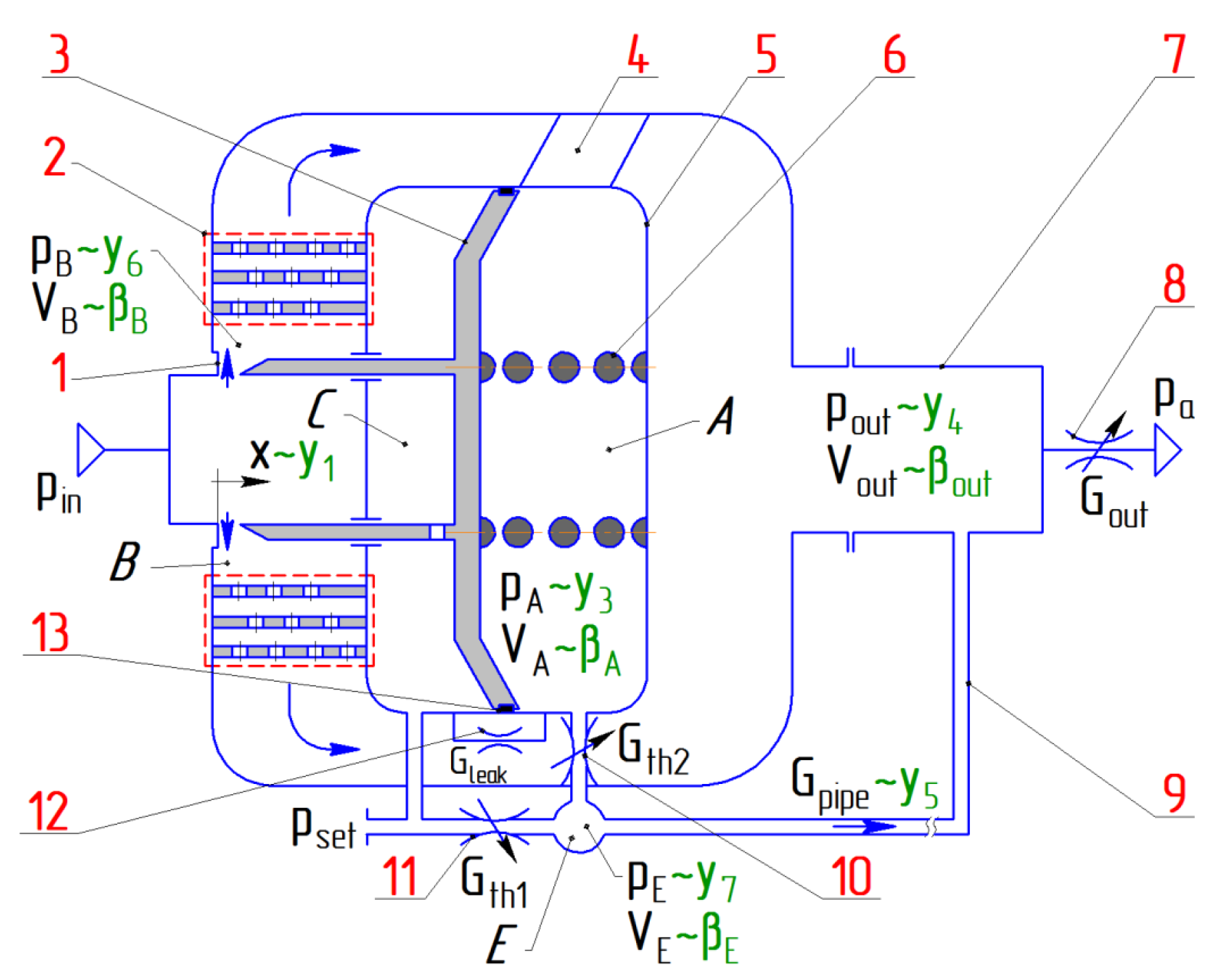
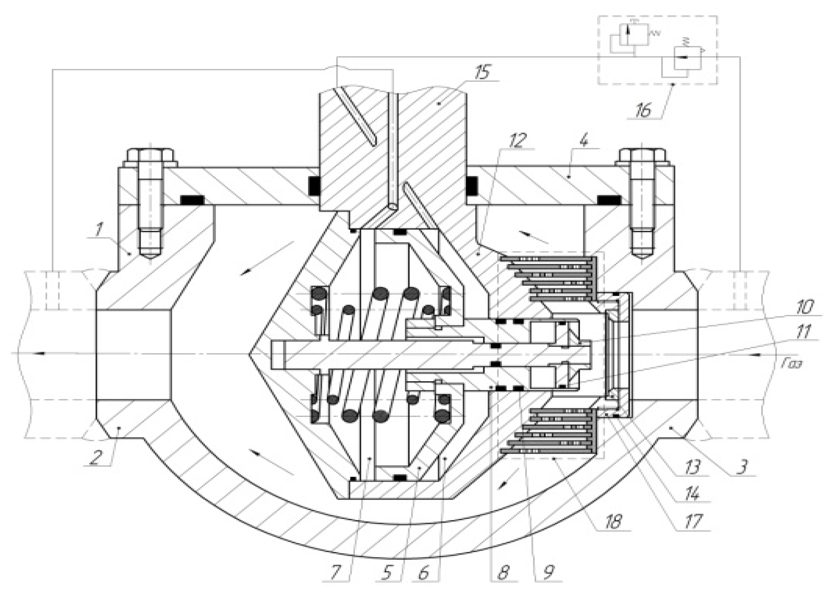
A schematic diagram of the studied gas pressure regulator is shown in Figure 1 with noise muffler 2 and throttle assembly 10, 11. The muffler design is shown in details in Appendix A (Figure A1 and Figure A2). The regulator’s task is to maintain a constant pressure pout in the outlet cavity Vout upsteam metering valve 8. The pressure value is determined by the setting pressure pset supplied to cavity C.
The system operates as follows. Gas with pressure pin enters the inlet of the regulator. In the absence of flow Gout (metering valve 8 is closed), the pressures in chambers A and C are equal to the setting pressure pset and valve 3 is pressed against the seat 1 by the force of the spring 6. When metering valve 8 is opened, the pressure in the outlet cavity and in cavity A, connected by the feedback pipeline 9, drops, and valve 3 opens, taking a position in accordance with the value of the steady-state flow rate in the system Gout. In this case, due to the low stiffness of the spring 6, the static pressure in cavity A and the pressure in the outlet cavity will slightly differ from the setting pressure pset.
Throttles 10 and 11 ensure the interaction of the cavities of the valve device with each other and with the feedback pipeline 9. Throttle 11 connects the control cavity with the feedback pipeline, thus contributing to increased sensitivity when setting the control pressure in the system by means of a setpoint reducer (not shown in the diagram). Throttle 10 sets the speed of filling the cavity A, thereby affecting the control rate. To simulate the gas leak from cavity A to cavity C through seal 13, throttle 12 is used.
In this study, we consider a silencer, which is a set of six perforated cylindrical thin-walled partitions (Figure A2). The area of the perforation holes increases from the first partition to the last one. The partitions are located at a close distance from each other, which makes it possible to neglect the volumes of the chambers between them. The muffler block can be installed both in close proximity to the throttling section of the regulator, and at some distance from it. In this regard, volume VB of the intermediate cavity B is included in the design model and can be different.
When compiling the model, the following assumptions are made: the working medium is an ideal gas, the processes of gas pressure changes in the cavities of the system are isentropic, the pressure drop across metering valve 8 is supercritical, and dry friction forces are negligible.
Variables used in the model are listed in Nomenclature table below. Indexes leak, set, th1, th2, A, B, C, E, out, pipe refer to throttling sections, cavities and feedback piping in accordance with Figure 1.
Then, the equation of motion of the valve as a dynamic element with lumped parameters can be represented as:
where m is the mass of the valve; J is the stiffness of the spring; D is the damping ratio; F0 is the spring pretension force; and Ap is the area of the sensing element of the valve; pA is the pressure in cavity A; pset is the set pressure in cavity C, taken constant.
Based on the Saint-Venant and Wanzel equation, the gas flow through the valve is determined by:
where Cd is the discharge coefficient; k is adiabatic exponent; R is specific gas constant; ds is the valve seat diameter; pin is the inlet pressure; pB is the pressure in cavity B.
Considering that the cavities of the muffler are negligible in comparison with the volumes of the cavities of the rest of the system, the muffler is considered as an active resistance. In this case, the equation for the mass flow rate through the muffler:
where kmuf is the muffler conductivity coefficient; —pressure drop over the muffler.
Assuming supercritical mode of the gas flow through the metering valve (), we can write the Saint-Venant and Wanzel equation:
where Aout is the area of a metering valve; pout is the outlet pressure.
Assuming that only the subcritical flow regime takes place at throttles 10, 11 and 12, and also assuming relatively small pressure drops, the flow equations can be written in a simplified form:
Taking into account the throttle block, the energy equations for variable mass of gas in cavities A and E can be written as:
As a feedback pipeline, we consider a pipeline of constant cross-section with a gas flow model in lumped parameters neglecting heat exchange with the environment. Then, the mass flow equation taking into account active and reactive resistances is:
where —reactive resistance of the pipe; —active resistance of the pipe for laminar flow.
To obtain more general solutions, it is expedient to represent the system of Equations (1)–(10) in dimensionless form. To do this, we introduce next dimensionless parameters characterizing valve displacement and speed, pressures in cavities A, B, E, and in the outlet cavity and gas flow rate in the feedback pipeline:
, , ,
, ,
Here, the maximum valve lift and the set pressure are taken as nominal values for the valve displacement and pressure: .
To switch to dimensionless time, the natural frequency of the valve unit as of a spring-mass system is used: , .
After transformations, the system of equations in dimensionless form looks as follows:
The calculated values of the controller parameters and the coefficients of Equation (11) are given in Table 1.
In the study of the stability of the steady state, the pressure pC in the control cavity C is assumed to be constant pC = pref = pset. Its value is determined by the setting of the setpoint reducer. For small deviations from the steady state, the pressure in the control cavity C always exceeds the pressure in cavity A and in the outlet cavity, i.e., pC > pA > pE > pout. Therefore, the gas flow in the throttles 10, 11 and 12 always occurs in the same direction at any flow rate not equal to zero. This allows for the avoidance of any uncertainty in the linearization of equations and provides stability analysis by the method of small deviations.
3. Steady State Characteristics of the Regulator
To find the steady state points at which the system stability can be studied, the system of Equation (11) at must be solved. The steady state characteristics of the regulator with and without a muffler were obtained in the authors’ previous work [13] and are presented in Figure 2.
As follows from Figure 2, the presence of a silencer does not affect the operation mode of the system with an increase of flow rate as long as the pressure drop across the throttling section of the valve is maintained at supercritical. However, as the flow rate increases, the pressure drop across the muffler increases too, and the pressure drop across the valve decreases, and when passing through the point with a flow rate of q = 5.9, the characteristic stratifies when the pressure pB upstream from the muffler reaches values corresponding to the subcritical flow through the valve.
The steady state characteristic in Figure 2 was obtained under the assumption that there is no gas leakage through the seal between cavity A and control cavity C [13]. However, experimental studies show the presence of a significant leakage between these cavities. To compensate for it and to adjust the steady state characteristic, throttles 10 and 11 are installed, and throttle 12 is introduced into the design model to simulate the leakage.
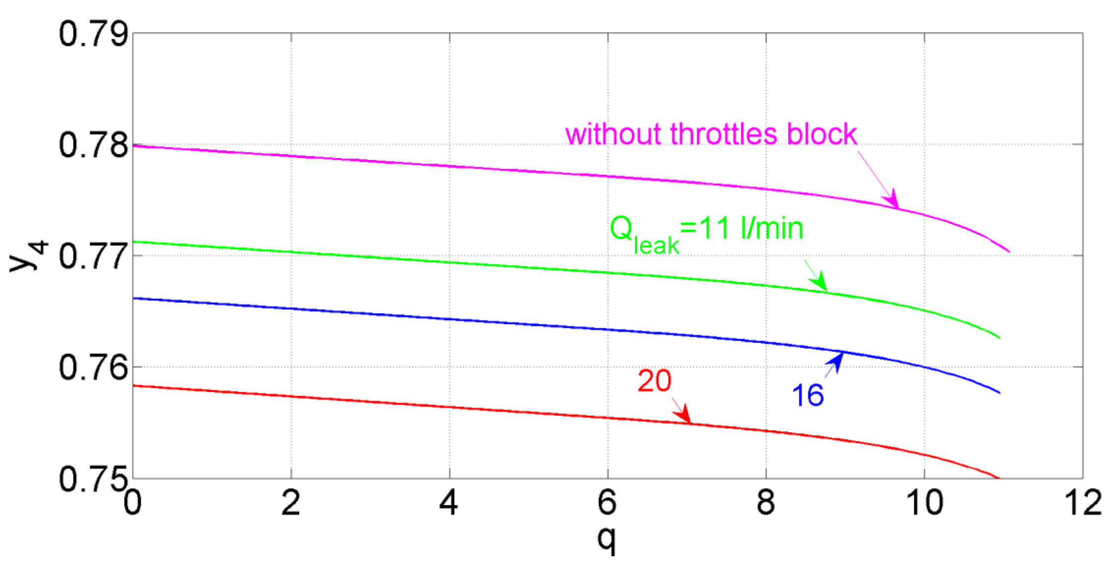
The steady state characteristic of the automatic control system in the presence of leaks between control cavity C and cavity A is shown in Figure 3.
As can be seen from the graphs, an increase of leakage leads to a decrease of the steady-state pressure in the output cavity (the equidistant displacement of the curve at with respect to the curve for a system without leakage is about 2%). This is due to the fact that additional gas flow into cavity A leads to an increase of pressure in it. In turn, an increase of pressure in cavity A leads to a decrease of the flow area of the valve (so that the balance of forces acting on the valve remains equal to zero with an increase of pressure in cavity A, the spring force must decrease). With a decrease of the valve flow area, the gas flow rate entering the output cavity decreases, as a result of which the pressure in it decreases.
4. Stability Analysis
To assess the stability of the system “in the small”, a method is used based on the analysis of the eigenvalues of the Jacobi matrix composed of the partial derivatives of the functions of the right-hand side of differential Equation (11) at the steady state points.
The Routh–Hurwitz criterion is used to analyze the eigenvalues of the characteristic equation and construct stability regions [14]. This classical criterion identifies the conditions when the poles of a polynomial cross into the right hand half plane and hence would be considered as unstable.
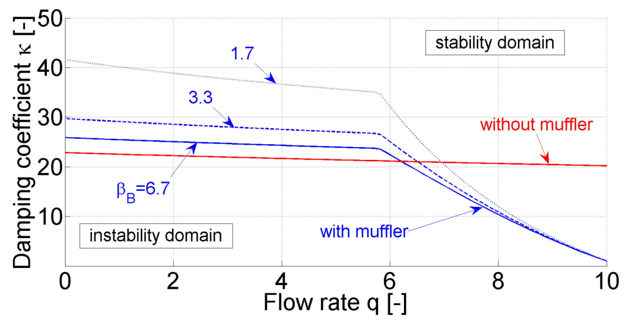
Figure 4 shows the deformation of the stability boundary when the stiffness of cavity B changes for a given stiffness of the outlet cavity in the flow rate range q from 0 to 10. These results were obtained in the authors’ previous work [13]. The curves on the graph are plotted for the boundary values of the damping coefficient k in accordance with the parameter values given in Table 1 and correspond to the minimum of the system damping required. From the analysis of the obtained graph, it follows that with an increase of the flow rate q and an increase of the stiffness of cavity B, the required damping decreases. It should also be noted that there is an inflection point in the curves associated with a change in the flow regime at the valve.
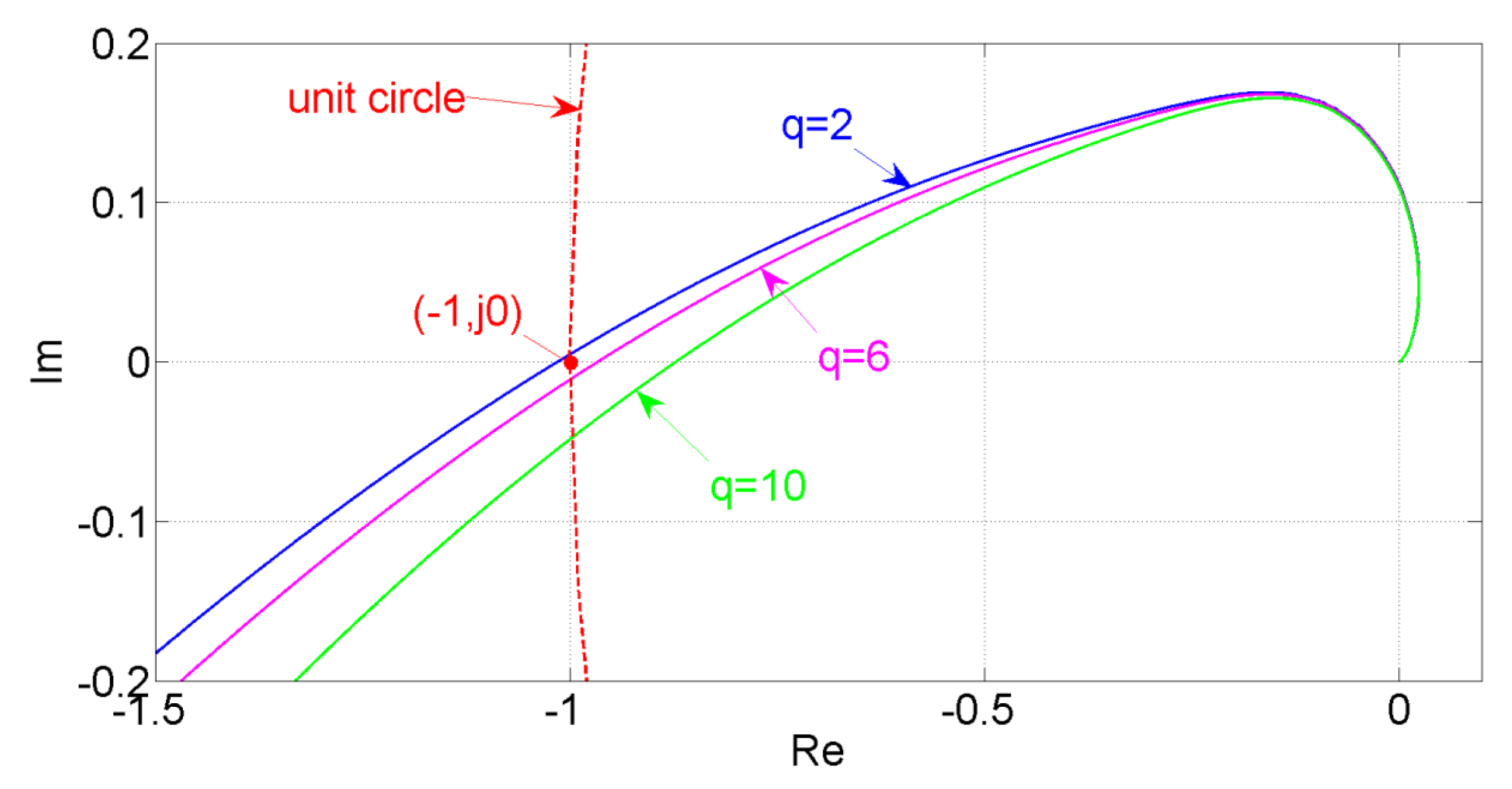
In the absence of a muffler, with increasing flow in the system, a slight decrease of the required damping is observed, which is explained by a decrease of the controller gain (the controller gain can be found by linearizing Equation (1) of the valve movement). Since with an increase of the flow rate, the value of the valve displacement y1 increases and the pressure in the outlet cavity y4 decreases, the gain decreases as well, which means that the coverage of the Nyquist plot, the point (−1; j0) on the complex plane will decrease (Figure 5).
Two characteristic zones can be distinguished for the stability boundary of the system with a silencer (Figure 4). In the region with supercritical flow through the valve, the required damping is greater than in the system without a silencer due to the appearance of cavity B and, accordingly, a time delay in the feedback loop. Moreover, the lower the stiffness of the cavity B is, the greater the delay and, accordingly, the required damping. As the flow rate in the system increases, the flow regime at the valve changes to subcritical at q = 5.9, which is accompanied by a decrease of the required damping. This is due to the change to the controller gain, which, in accordance with the steady-state characteristics, begins to decrease faster with increasing flow rate than in the supercritical mode. At the same time, with the onset of the subcritical flow regime, the pressure drop across the muffler becomes greater than that across the valve. As a result, the constant resistance of the muffler serves as an additional source of damping.
5. Influence of the Block of Throttles on the Stability of the Regulator with a Silencer
Figure 6 shows the stability domain in the plane of dimensionless flow rate q and stiffness of the outlet cavity. The stability limits are calculated at constant values of the area of throttles 10 and 11 (Figure 1). It can be noted that taking into account the choke block in the presence of leakage between the cavities of the valve device leads to a significant expansion of the stability domain in comparison with that for the original system. The presence of gas leakage between the cavities contributes to additional energy dissipation during valve oscillations. Moreover, with an increase of leakage, the stability region expands, since there is “an equalization” of pressures between the cavities and, consequently, a decrease of the disturbing force.
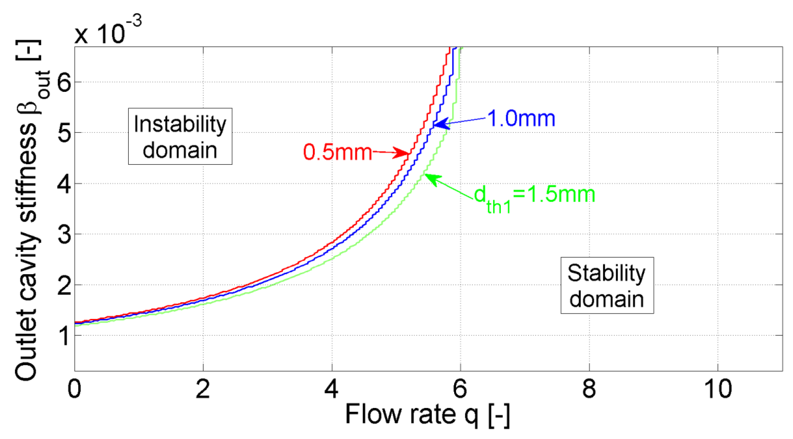
It should be noted that the throttle 10 also significantly contributes to the damping of the system due to the influence of its active resistance for the propagation of the pressure signal between the outlet cavity and cavity A (Figure 7). A decrease of the flow area of this throttle leads to an increase of pressure losses and an expansion of the stability region.
Changing the flow area of throttle 11 affects the system stability to a lesser extent in comparison with the parameters described above (Figure 8). This is due to the absence of a direct influence of this parameter on the pressure in cavity A. However, a decrease of the flow area of throttle 11 leads to an expansion of the stability domain due to an increase of pressure losses by analogy with throttle 10.
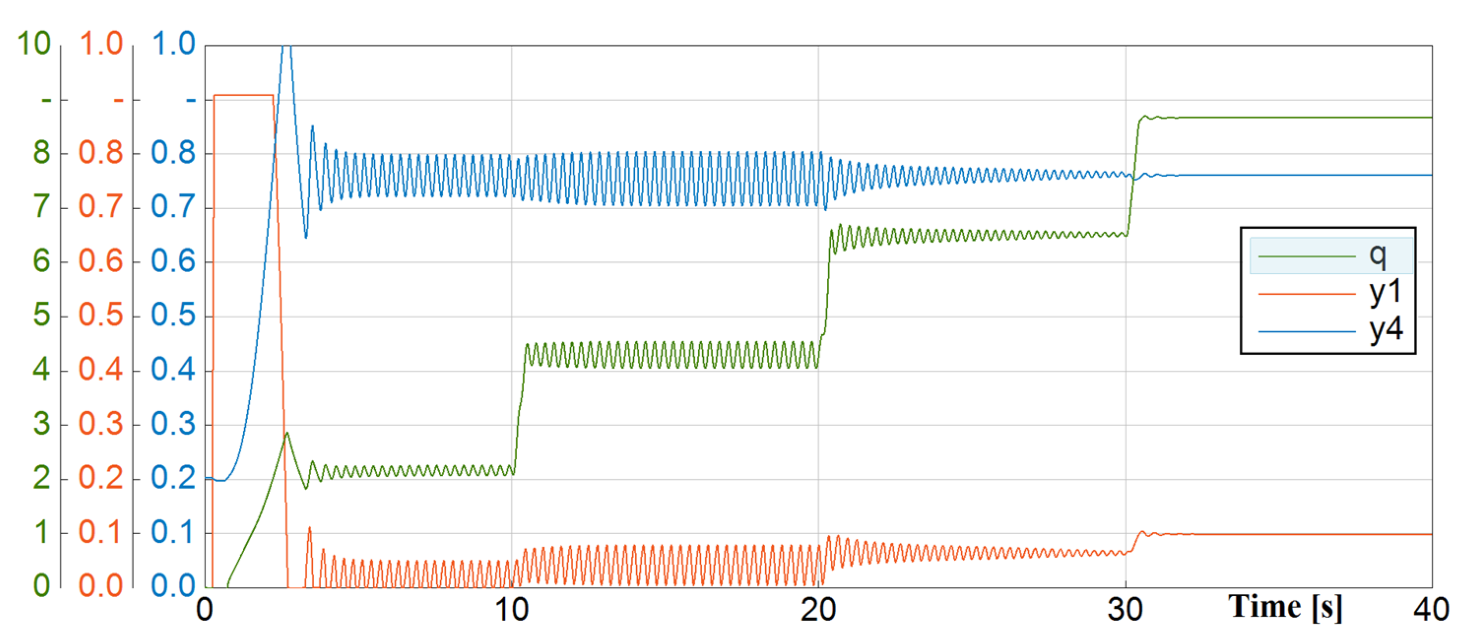
Figure 9 shows the simulation results in the form of transient processes of changes in valve position, pressure in the outlet cavity and flow rate in the system with a stepwise increase of the flow area of metering valve 8 (Figure 1). The obtained calculations show that for the selected combination of parameters over the flow rate range from q = 0 to q = 5, the system has unstable equilibrium points, which is consistent with the research results above.
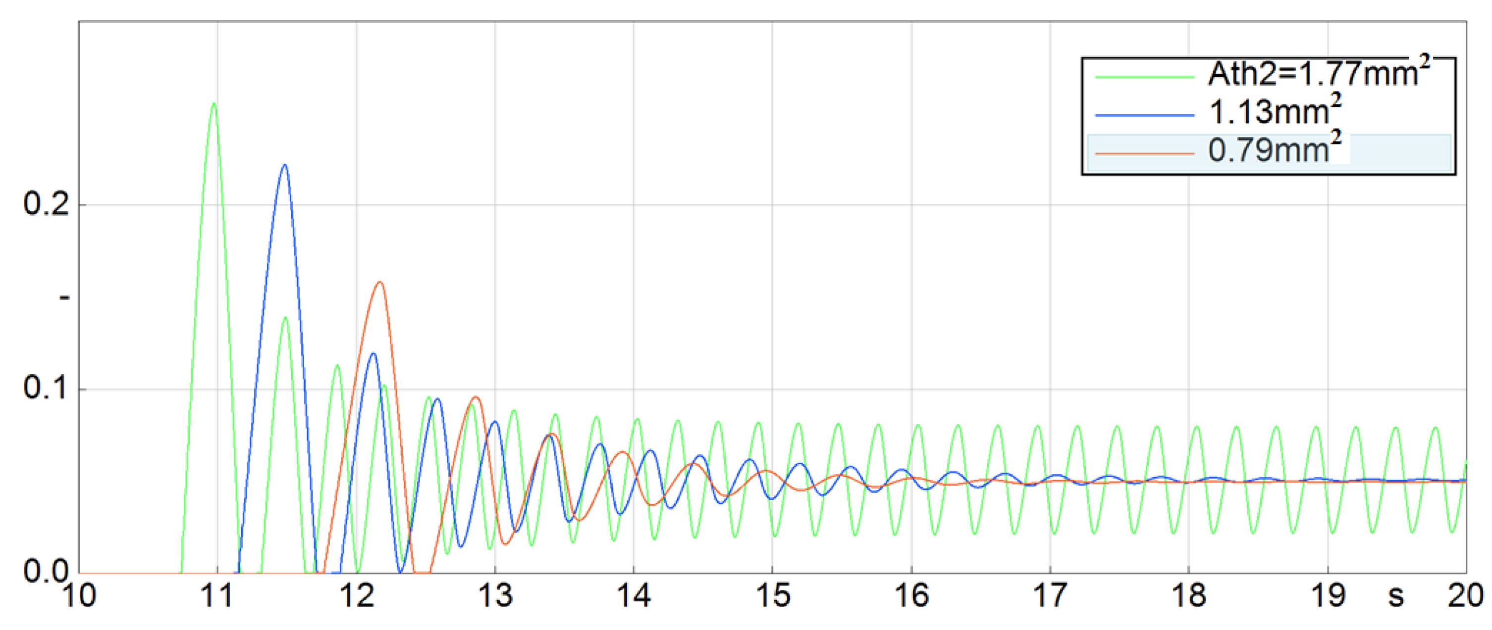
Figure 10 and Figure 11 show the simulation results in the form of transient processes in the valve position with a stepwise opening of metering valve 8 by an amount corresponding to the flow rate q = 5. From the analysis of the results, it follows that with an increase of leakage between cavities A and C, the step response time, the amplitude and frequency of oscillation decrease and the system becomes more stable.
A decrease of the flow area of the throttle 10 contributes to a decrease of the oscillation of transient processes and an increase of the stability of the system; however, this reduces the control rate due to an increase of the filling time of cavity A.
The analysis shows a significant effect of leakage in the valve device simulated by throttle 12 and throttle 10 installed in the feedback pipeline on dynamic properties of the automatic control system. In this case, throttle 10 affects both the stability and control rate. The study of the effect of leakage, as an unforeseen phenomenon in the system, shows that the presence of a bypass flow between the cavities can have a beneficial effect on the stability of the system with a slight decrease of accuracy. In this regard, according to preliminary data, to increase the reliability and resource of the gas downstream pressure controller (of the considered typical design), a regular gas bypass between the control cavities of the actuator can be used by installing an adjustable throttle. A more detailed estimation can be given based on the results of future experimental studies.
6. Conclusions
The article presents a mathematical model of a modernized gas pressure regulator with a built-in noise suppressor. An assessment of the influence of the parameters of the silencer and the package of chokes on the stability and dynamic characteristics of the regulator is given. It is shown that the installation of a silencer contributes to an increase of the stability of the system in the range of high gas flow rates, when a subcritical flow regime is realized on the valve. In the range of relatively low gas flow rates, the installation of a silencer reduces stability. However, the stability region expands with a decrease of the volume of the cavity between the valve and the muffler. The obtained results make it possible to optimize the design of the regulator based on the requirements of the stability and acoustic efficiency of the muffler.
The work also investigates the effect of gas leakage through the seal of the piston of the sensing element. It is shown that the presence of a certain leakage in the regulator of this design can have a positive effect on stability with a slight decrease of accuracy. A more detailed assessment can be given based on the results of experimental studies with various seal designs. The design of the sensing piston seal affects not only the amount of gas leakage, but also the friction force of the piston, which, in turn, affects the accuracy and stability of the regulator. According to the results of experimental studies, the mathematical model of the regulator can be adjusted by taking into account the friction force.
In general, theoretical studies confirm the adequacy of the mathematical model of the modernized gas pressure controller with the built-in silencer and the package of chokes. The model can be used when designing a regulator and analyzing its dynamic performances and stability as part of a gas-transmission system. Future research will be directed to experimental studies of this regulator across the entire range of required static and dynamic characteristics and acoustic efficiency of the muffler.
Author Contributions
Conceptualization, V.S. and D.S.; methodology, V.S.; software, D.S.; validation, V.I. and M.B.; formal analysis, V.S.; investigation, D.S.; resources, A.I.; data curation, D.S.; writing—original draft preparation, D.S.; writing—review and editing, V.S. and E.S.; supervision, V.S. and A.I.; project administration, E.S.; funding acquisition, A.I. All authors have read and agreed to the published version of the manuscript.
Funding
This research received no external funding.
Data Availability Statement
No new data were created or analyzed in this study. Data sharing is not applicable to this article.
Acknowledgments
The authors are grateful to Ministry of Education and Science of the Russian Federation for their administrative and technical support.
Conflicts of Interest
The authors declare no conflict of interest.
Nomenclature
| A | Area | [m2] |
| a | Sound speed | [m/s] |
| Cd | Discharge coefficient | [-] |
| D | Viscous drag coefficient | [Ns/m] |
| d | Diameter | [m] |
| F | Force | [N] |
| G | Mass flow rate | [kg/s] |
| J | Spring stiffness | [N/m] |
| l | Length | [m] |
| m | Mass of moving unit | [kg] |
| p | Pressure | [Pa] |
| R | Specific gas constant | J/kg/K |
| T | Temperature | [K] |
| V | Volume | [m3] |
| x | Valve displacement | [m] |
| ρ | Density | [kg/m3] |
| ν | Kinematic viscosity | [m2/s] |
| ω | Cyclic frequency | [1/s] |
Appendix A
Figure A1.
Investigated gas pressure regulator with built-in muffler (no 18).

Figure A2.
Muffler block disassembled.

References
- Pressure Regulators in Gas-Fired Power Plant Feed Applications, White Paper, D352835X012. Available online: https://www.emerson.com/documents/automation/white-papers-pressure-regulators-in-gas-fired-power-plant-feed-applications-fisher-en-en-6157412.pdf (accessed on 20 January 2022).
- Ver, I.L.; Beranek, L.L. (Eds.) Noise and Vibration Control Engineering: Principles and Applications, 2nd ed.; Wiley: Hoboken, NJ, USA, 2006. [Google Scholar]
- Chen, F.; Qian, J.; Chen, M.; Zhang, M.; Chen, L.; Jin, Z. Turbulent compressible flow analysis on multistage high pressure reducing valve. Flow Meas. Instrum. 2018, 61, 26–37. [Google Scholar] [CrossRef]
- Chen, F.; Gao, Z.; Qian, J.; Jin, Z. Numerical study on flow characteristics in high multi-stage pressure reducing valve, Advances in Numerical Modeling for Turbomachinery Flow Optimization. In Proceedings of the Fluid Machinery, Industrial and Environmental Applications of Fluid Mechanics, Pumping Machinery, ASME 2017 Fluids Engineering Division Summer Meeting, Waikoloa, HI, USA, 30 July–3 August 2017; Volume 1A, p. V01AT03A013. [Google Scholar] [CrossRef]
- Chen, F.; Zhang, M.; Qian, J.; Chen, L.; Jin, Z. Pressure analysis on two-step high pressure reducing system for hydrogen fuel cell electric vehicle. Int. J. Hydrogen Energy 2017, 42, 11541–11552. [Google Scholar] [CrossRef]
- Stadnik, D.M.; Igolkin, A.A.; Sverbilov, V.Y.; Afanasev, K.M. The muffler performance effect on pressure reducing valve dynamics. Procedia Eng. 2017, 176, 706–717. [Google Scholar] [CrossRef]
- Vujić, D.; Radojković, S. Dynamic model of gas pressure regulator. Facta Univ. Ser. Mech. Autom. Control Rob. 2001, 3, 269–276. [Google Scholar]
- Zafer, N.; Luecke, G.R. Stability of gas pressure regulators. Appl. Math. Model. 2008, 32, 61–82. [Google Scholar] [CrossRef] [Green Version]
- Shahani, A.R.; Esmaili, H.; Aryaei, A.; Mohammadi, S.; Najar, M. Dynamic simulation of a high pressure regulator. J. Comput. Appl. Res. Mech. Eng. 2011, 1, 17–28. [Google Scholar] [CrossRef]
- El Golli, R.; Bézian, J.-J.; Delenne, B.; Menu, F. Modeling of a pressure regulator. Int. J. Press. Vessel. Pip. 2007, 84, 234–243. [Google Scholar]
- Sun, B.; Xu, Q.; Chen, Y. Dynamic modeling and simulation of a pressurized system used in flight vehicle. Chin. J. Aeronaut. 2018, 31, 1232–1248. [Google Scholar] [CrossRef]
- Nabi, A.; Wacholder, E.; Daan, J. Dynamic model for a dome-loaded pressure regulator. J. Dyn. Sys. Meas. Control 2000, 122, 290–297. [Google Scholar] [CrossRef]
- Shakhmatov, E.V.; Igolkin, A.A.; Sverbilov, V.Y.; Stadnik, D.M.; Ilyukhin, V.N. Studies of the Characteristics of a Gas Pressure Regulator with a Noise Suppressor. J. Mach. Manuf. Reliab. 2021, 50, 481–488. [Google Scholar] [CrossRef]
- Sagharchi, F. Routh-Hurwitz Stability Criterion. MATLAB Central File Exchange. Retrieved 18 December 2022. Available online: https://www.mathworks.com/matlabcentral/fileexchange/17483-routh-hurwitz-stability-criterion (accessed on 30 September 2022).
Figure 1.
Schematic diagram and main nomenclature for the GPR with muffler. 1—valve seat; 2—muffler; 3—piston/sensing element/valve; 4—pylon; 5—valve body-; 6—spring; 7—outlet pipe; 8—metering valve; 9—feedback pipe; 10, 11—variable throttle; 12—leak simulator; 13—seal.
Figure 1.
Schematic diagram and main nomenclature for the GPR with muffler. 1—valve seat; 2—muffler; 3—piston/sensing element/valve; 4—pylon; 5—valve body-; 6—spring; 7—outlet pipe; 8—metering valve; 9—feedback pipe; 10, 11—variable throttle; 12—leak simulator; 13—seal.

Figure 2.
Steady state characteristic of the regulator: the valve displacement y1 as a function of the flow rate q [13].
Figure 2.
Steady state characteristic of the regulator: the valve displacement y1 as a function of the flow rate q [13].

Figure 3.
Output pressure y4 as a function of flow rate q at various leakages between cavities A and C ( ).
Figure 3.
Output pressure y4 as a function of flow rate q at various leakages between cavities A and C ( ).

Figure 4.
Stability boundaries for various stiffness of the cavity B [13].
Figure 4.
Stability boundaries for various stiffness of the cavity B [13].

Figure 5.
Nyquist plot for various flow rates q.

Figure 6.
Stability domains at various leakage value k for the constant areas of throttles 10 and 11 ( ).
Figure 6.
Stability domains at various leakage value k for the constant areas of throttles 10 and 11 ( ).

Figure 7.
Stability domains at various diameter of throttle 10 for the constant values of leakage and area of throttle 11 Ath1 ( ).
Figure 7.
Stability domains at various diameter of throttle 10 for the constant values of leakage and area of throttle 11 Ath1 ( ).

Figure 8.
Stability domains at various diameter of throttle 11 for the constant values of leakage and area of throttle 10 ( ).
Figure 8.
Stability domains at various diameter of throttle 11 for the constant values of leakage and area of throttle 10 ( ).

Figure 9.
Time responses for flow rate q, valve displacement y1 and output pressure y4 with a stepwise increase of the area of metering valve 8 at the constant values of leakage, areas of throttles 10 and 11, and outlet cavity stiffness (; ; ).
Figure 9.
Time responses for flow rate q, valve displacement y1 and output pressure y4 with a stepwise increase of the area of metering valve 8 at the constant values of leakage, areas of throttles 10 and 11, and outlet cavity stiffness (; ; ).

Figure 10.
Valve displacement y1 step responses for various leakage Qleak with a stepwise increase of the area of metering valve 8 at the constant values of areas of throttles 10 and 11, and outlet cavity stiffness ().
Figure 10.
Valve displacement y1 step responses for various leakage Qleak with a stepwise increase of the area of metering valve 8 at the constant values of areas of throttles 10 and 11, and outlet cavity stiffness ().

Figure 11.
Valve displacement y1 for various area of throttle 10 (Ath2) with a stepwise increase of the area of metering valve 8 at the constant values of area of throttle 11 leakage , and outlet cavity stiffness .
Figure 11.
Valve displacement y1 for various area of throttle 10 (Ath2) with a stepwise increase of the area of metering valve 8 at the constant values of area of throttle 11 leakage , and outlet cavity stiffness .


Table 1.
Parameters of the studied controller.
| Name | Symbol | Definition | Value |
|---|---|---|---|
| Reference pressure | 0.5 [MPa] | ||
| Reference displacement | 11 [mm] | ||
| 27.7 | |||
| Natural frequency of the valve | 120 [rad/s] | ||
| Flow rate coefficient | q | 0–12 | |
| Muffler conductivity coefficient | 0.34 × 10⁻⁶ [kg/s/Pa] | ||
| Relative inlet pressure | Kp | 10 | |
| Spring preload ratio | 4.77 | ||
| Stiffness of cavity B | 0.2–6.7 | ||
| Stiffness of cavity A | 0.54–0.90 | ||
| Outlet cavity stiffness | 3.3 × 10⁻⁴–3 × 10⁻² | ||
| Stiffness of cavity E | 2 × 10⁸ [1/m/s] | ||
| Reference stiffness of cavity A | 4.2 × 10⁶ [1/m/s] | ||
| Damping coefficient | 0–300 | ||
| Natural frequencies ratio factor | 0.55 | ||
| Feedback pipeline natural frequency factor | 105.0 | ||
| Acoustic capacitance factor | 1.43 × 10⁻⁹ | ||
| Feedback pipeline loss factor | 0.2–20 | ||
| Subcritical flow rate coefficient | Sub | 304.2 | |
| Supercritical flow rate coefficient | Sup | 78.7 | |
| 2 × 10⁻¹⁰–2 × 10⁻⁹ [m·s] | |||
| 8 × 10⁻¹⁰–7 × 10⁻⁹ [m·s] | |||
| 8 × 10⁻¹⁰–7 × 10⁻⁹ [m·s] | |||
| E | 0.004 [s/m] | ||
| B | 0.0019 [s/m] | ||
| Reference area of the valve | 0.0014 [m2] |
Disclaimer/Publisher’s Note: The statements, opinions and data contained in all publications are solely those of the individual author(s) and contributor(s) and not of MDPI and/or the editor(s). MDPI and/or the editor(s) disclaim responsibility for any injury to people or property resulting from any ideas, methods, instructions or products referred to in the content. |
© 2022 by the authors. Licensee MDPI, Basel, Switzerland. This article is an open access article distributed under the terms and conditions of the Creative Commons Attribution (CC BY) license (https://creativecommons.org/licenses/by/4.0/).
Share and Cite
MDPI and ACS Style
Stadnik, D.; Sverbilov, V.; Ilyukhin, V.; Igolkin, A.; Balyaba, M.; Shakhmatov, E. Study on Stability of Gas Pressure Regulator with a Built-In Silencer. Energies 2023, 16, 372. https://0-doi-org.brum.beds.ac.uk/10.3390/en16010372
AMA Style
Stadnik D, Sverbilov V, Ilyukhin V, Igolkin A, Balyaba M, Shakhmatov E. Study on Stability of Gas Pressure Regulator with a Built-In Silencer. Energies. 2023; 16(1):372. https://0-doi-org.brum.beds.ac.uk/10.3390/en16010372
Chicago/Turabian StyleStadnik, Dmitry, Victor Sverbilov, Vladimir Ilyukhin, Alexander Igolkin, Maxim Balyaba, and Evgeniy Shakhmatov. 2023. "Study on Stability of Gas Pressure Regulator with a Built-In Silencer" Energies 16, no. 1: 372. https://0-doi-org.brum.beds.ac.uk/10.3390/en16010372
Note that from the first issue of 2016, this journal uses article numbers instead of page numbers. See further details here.