
Design Modifications for a Thermoelectric Distiller with Feedback Control

1
The Mechanical and Industrial Engineering Department, Applied Science Private University, Amman 11931, Jordan
2
Mechanical Engineering Department, King Fahd University for Petroleum and Minerals, Dhahran 31261, Saudi Arabia
*
Author to whom correspondence should be addressed.
Energies 2022, 15(24), 9612; https://0-doi-org.brum.beds.ac.uk/10.3390/en15249612
Submission received: 5 November 2022
/
Revised: 14 December 2022
/
Accepted: 15 December 2022
/
Published: 18 December 2022
(This article belongs to the Special Issue Advanced Studies of Thermoelectric Systems)
Abstract
:In this paper, a modified design for a thermoelectric distiller is proposed, constructed, and tested. The design modifications include adding an inclined cover for the thermoelectric module and a cooling fan. The thermoelectric module and the fan were operated by an open loop or a feedback control to have the desired productivity. As the distiller productivity depends on the operating conditions, these operating conditions are investigated to find the best performance with the highest pure water productivity. Furthermore. a comparison between the closed and the open loop for driving the cooling fan with different operating conditions is conducted. In this work, the mathematical model of the proposed distiller is derived. Experimental results illustrate the robustness of the proposed approach and they show that the suggested thermoelectric distiller with feedback control, for both cases with MPC and PID controllers, can increase pure water productivity by up to 150% when compared with the open loop thermoelectric distiller.
1. Introduction
Distilled water is essential in many human practices, as it is used for many industrial and medical applications, such as the manufacture of medicines, laboratory analyzes, the manufacture of batteries, and ironing clothes [1]. However, the process of producing distilled water is challenged by the high energy consumption, due to the need to evaporate the water before condensing it [2]. It should be noted that the latent energy and the heat capacity of water are significantly high, leading to the consumption of a lot of energy, most of which is wasted. This high energy consumption is reflected in the environment since most distillation devices depend on electrical energy generated mostly from burning fossil fuels. Therefore, the active research community has studied several methods to obtain energy-efficient, low-cost, environment-friendly, and high-yield distillers.
Recently, many environment-friendly distillation designs tackled the challenge of adding a thermoelectric module (TEM) within the distiller apparatuses. TEM is a semiconductor device, that works based on the Seebeck effect. Thus, TEM is used in two ways. The first TEM application includes converting electrical energy to heat flux. The second usage opposes the first one because the TEM is exposed to heat flux converted into electrical energy. Recently, there has been considerable interest in TEM scientific research, in particular for the environment-friendly distillation process, and this is due to TEM’s interesting properties. One of its remarkable properties is its ability to heat and cool simultaneously. In other words, TEM can generate heat flux or pump heat energy between its hot and cold sides. This process results in temperature differences between TEM sides. Because of this property, TEM can be utilized for water distillers, mainly considering three methodologies: (1) TEM is used as a secondary element for increasing the water condensation rate by placing the TEM cold side in touch with the vapor. Several works considered using the thermoelectric module to enhance the vapor condensation in solar distillers [3,4,5,6]. (2) TEM is a secondary element to increase water evaporation in solar distillers. In this case, the TEM hot side is attached to the saline water tank or the solar distiller basin [7]. (3) TEM is a primary source for heating the saline water and cooling the vapor. In this case, the TEM hot side is attached to the hot tank while the other TEM side is placed on the distiller cold tank. This way, the TEM restores the heat from the vapor and pumps it back to the hot tank for heating and boiling the saline water. Recently, several research methodologies were proposed considering TEM as a primary element. For example, the multi-stage design [8], the concentric design of the thermoelectric distiller [9,10], and the usage of thermoelectric distiller in urine–water recovery systems inside spacecraft [10,11]. Additionally, recent works tackled the use of the thermoelectric module to enhance vapor condensation and cooling in solar distillers [3,12].
Another interesting study presented thermoelectric utilization to improve saline water evaporation and condensation [13,14]. Such a proposed device employed a pump for recirculating the saline water between the water basin and the heat exchanger coupled to the hot side of the thermoelectric module. The cold side of the thermoelectric module is used for vapor condensation. This approach shows better energy conservation. However, the limitation of using a pump for water circulation will increase the required operational power. Moreover, to the best of our knowledge, no control strategy is proposed resulting in optimal productivity. A promising work proposed a simplified mathematical model for a thermoelectric-based distiller and compared it through experimental validation [15]; it proposed a new distiller design that is very efficient and has lower power consumption with high-purity water production. Nonetheless, the shortcoming of the work by [15] is wasting 45% of the input water through the system vent. This considerable loss is due to the vapor production rate being higher than the condensation rate. As a result, a considerable amount of vapor comes out of the distiller through a vent to conserve the constant pressure in the system. Similar work proposes a thermoelectric-based distiller by deriving a polynomial function for predicting the water evaporation rate with time [16]. The second TEM property is the ability to generate electrical power through the temperature difference between hot and cold sides. This property is employed to generate electricity from the heat losses in distillers [17]. The main challenge with this type of TEM application is its low efficiency since the thermoelectric generator efficiency is less than 20% [18]. This limitation reduces the TEM usage as a generator for low-temperature harvesting applications (e.g., water distillers).
Motivated by the abovementioned challenges, in this work, a modified TEM distiller is proposed, where the TEM is considered as a primary element such that both hot and cold sides are utilized in the evaporation and condensation stages. The main objective of this work is to improve the productivity of the TEM distiller through different design modifications summarized as follows:
- The main contribution is the modified thermoelectric design. This new design includes adding a heat sink with a fan to the distiller cold tank outer face to attenuate the heat effect from the system. This facilitates controlling the temperature of the distiller cold tank.
- Proposing a closed loop feedback control method where the output performance is compared with standard open loop control methods.
- Proposing and implementing two feedback control systems, PID and MPC controllers, to control the operation of the thermoelectric distiller by manipulating the rotational speed of the fan and the TEM input voltage in the MPC case. The proposed control strategy successfully handles various unknown disturbances keeping the system at the desired operating conditions.
- Additionally, an inclined cover of the thermoelectric distiller has been introduced to facilitate the collection of condensed drops of distilled water.
2. System Description
In this section, the proposed system parts and working principles are illustrated. Main distiller design modifications will be presented, followed by the mathematical model of the system, which consists mainly of energy and heat balance equations. Finally both steady-state and dynamic thermal model is derived.
2.1. The Proposed Thermoelectric Distiller Design
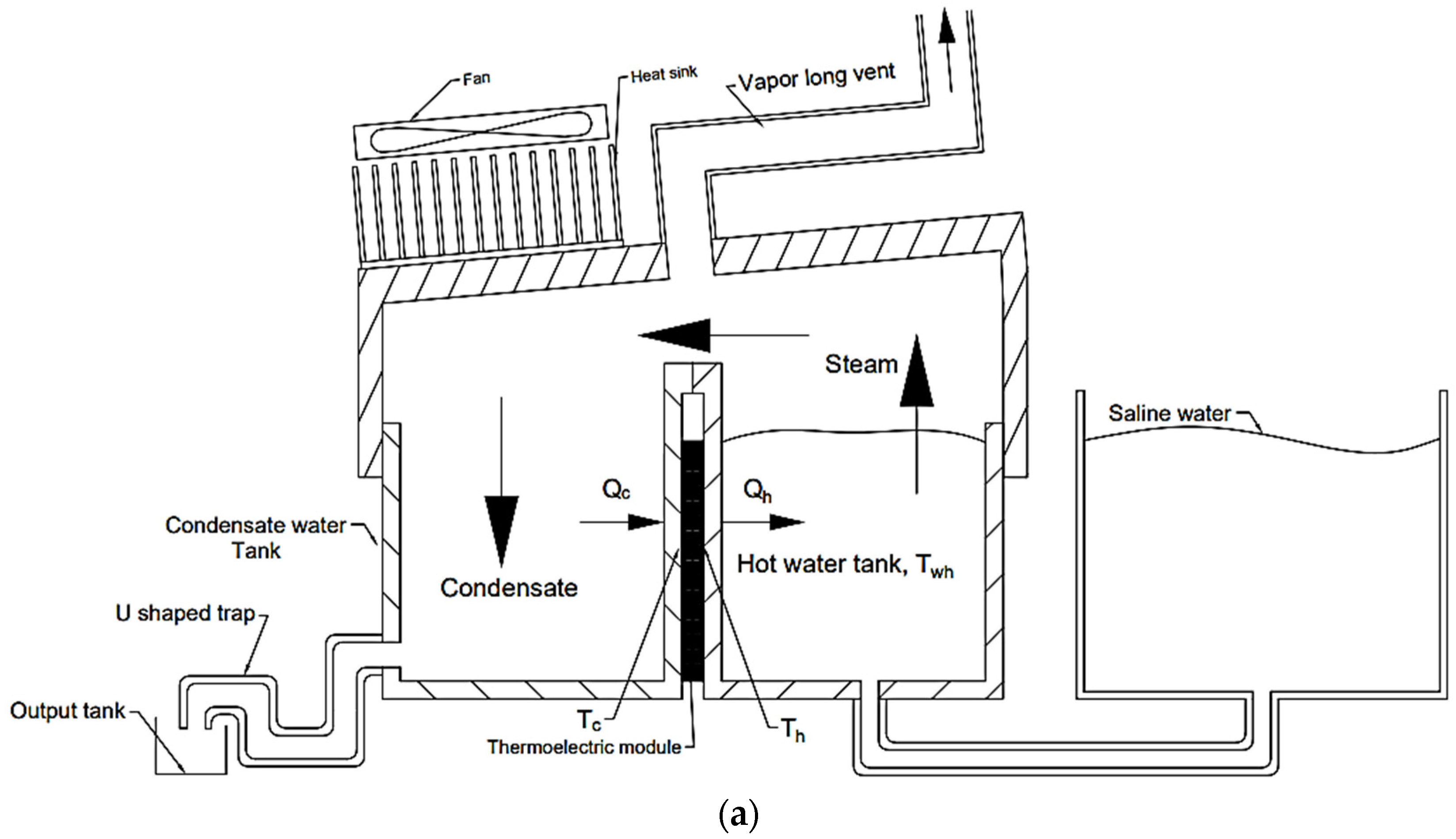
The proposed design of the thermoelectric module distiller (TEMD) uses the hot side of the thermoelectric module (TEM) to heat the water to the boiling point. The cold side is used to condensate the vapor and to recover a part of the vapor’s latent heat to the hot side for reusing it. Figure 1 shows the main parts of the TEMD, which are two separate (casted aluminum) tanks, hot and cold tanks (9 × 5 × 5 cm each tank), a cover, and two TEM modules. The right tank includes hot water (saline water), and the left tank is for distilled water. The two TEMs are sandwiched between these two tanks in parallel. The condensed water in the cold tank loses a part of its latent heat to be pumped back to the hot tank by TEM. As a result, the waste energy will be reduced. However, heat losses occur in the hot and cold tanks to the surroundings, and vapor escapes from the vent when the distiller pressure increases. So, to keep the system in steady, a heat sink with a cooling fan is used to increase cooling and prevent water vapor from accumulating inside the system by condensing it and avoiding any vapor losses. The heat sink is fixed on the top of the cover over the cold tank. The fan is mounted above the heat sink. The primary function of the fan and the heat sink is to get rid of the excessive amount of energy to keep the process in a balanced state with maximum productivity.
The saline water tank is piped with the hot tank from both bottoms. This connection decreases heat loss because hot water has a lower density than cold water. As a result, the hot water will not flow through the pipe, minimizing heat losses. On the other hand, controlling the water level in the hot tank will be easily obtained by controlling the water level in the saline water tank. The water level is very low in the cold tank, and the condensed water film will cover the inside walls. The cold tank is attached to a U-shaped pipe to prevent the vapor from escaping from the tank while allowing only the distilled water to leave. A vent through the cover of the distiller is connected with a long pipe. This arrangement is required to keep the inside pressure near the atmospheric pressure and to prevent vapor accumulation in the hot tank.
The inside cover face is inclined to make the condensate water drops slide to the cold tank, which increases productivity.
2.2. Mathematical Modeling of the System
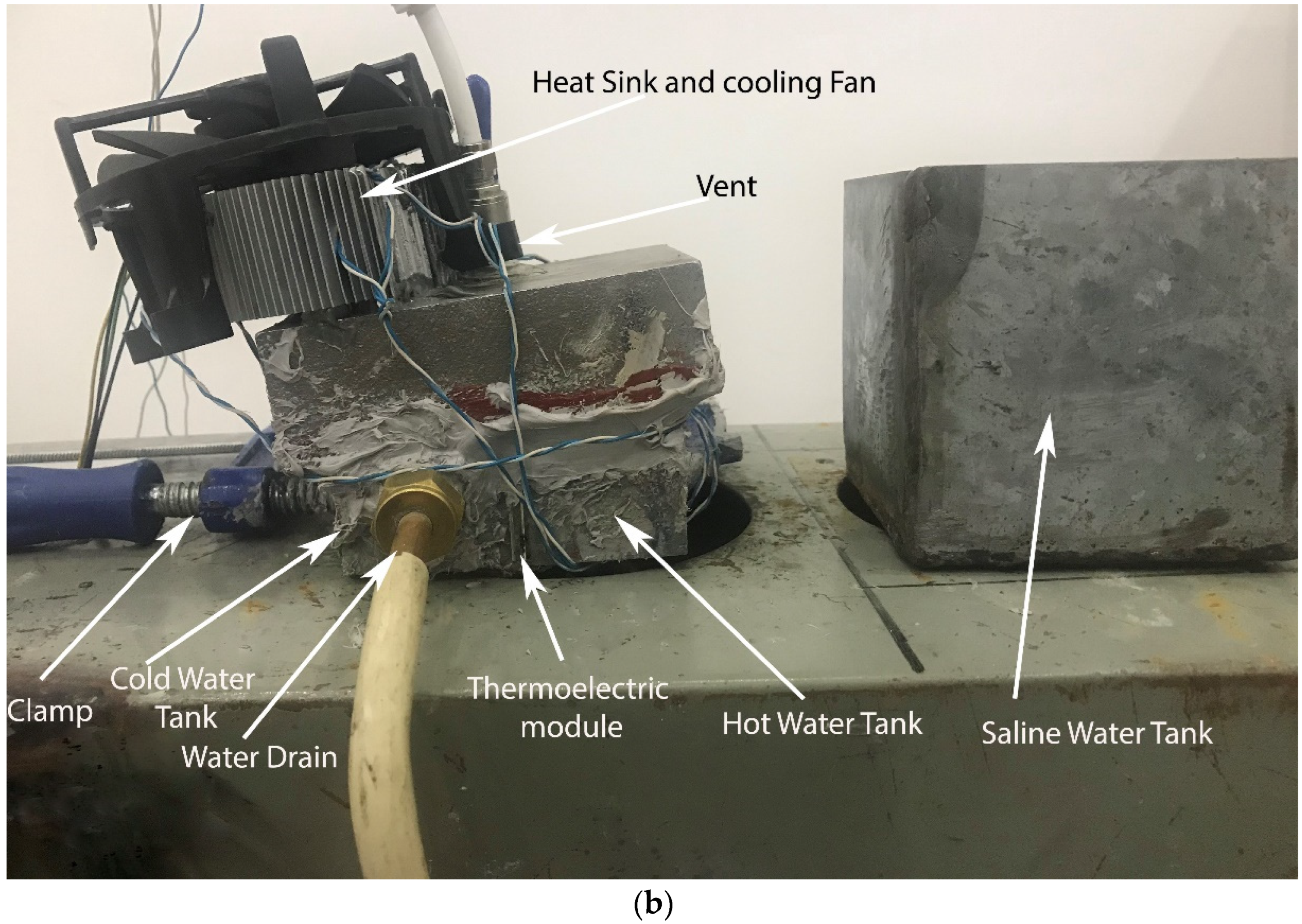
In this section, a mathematical model of the proposed system is derived. A similar model was validated in [15]. This model represents energy balance, mass balance, and heat transfer equations. The thermal model can be simplified into three main areas: the TEM model, the hot tank model, and the cold tank model, as shown in Figure 2.
The first thermal zone is TEM. The TEM model is given in [18,19]. Since we have an number of the TEMs connected thermally in parallel, and electrically in series, the equations will be as follows:
where and are, respectively, the heat flow rate to the hot side and the heat flow rate entering from the cold side of the thermoelectric module. is the Seebeck coefficient, is the electric resistance, k is the thermal conductance of the thermoelectric module, and . The thermoelectric module type used is TEC1-19908, and its characteristics are validated experimentally by applying a simple least square fitting procedure for collected voltage, current, and temperature readings as in Equation (3). The TEM characteristics are ≅ 0.088 V/K, R ≅ 2.38 , and k ≅ 0.8889 W/K.
The second thermal zone is for the hot tank. Heat convection from the hot side of TEM to the water inside the hot tank is found using Equation (4), and heat loss from the water in the hot tank to the surroundings is found in Equation (5):
The resultant dynamic energy balance equation is:
The related steady energy balance equation is:
The vapor loss due to the vent and the corresponding vapor energy loss are given in the following equation:
The third thermal zone is the cold tank volume. Equation (9) represents the convection heat transfer from the cold side of TEM to the condensed water film that covers the cold tank walls. Equations (10) and (11) formulate heat loss from the vapor and the condensed water film to the surroundings. For simplification, the thermal resistance is assumed to be the same for both losses.
Equation (12) represents the dynamic heat balance in the cold tank, which can be used to find the condensation mass flow rate.
Equation (13) represents the steady-state heat balance.
Note that the in the cold tank depends on the fan rotational speed.
- (A)
- To simplify the model, the following assumptions were used:
- (B)
- while boiling.
- (C)
- in the hot tank.
- (D)
- The distiller pressure is equal to the atmospheric pressure due to the small vent in the design.
- (E)
- The thermal heat transfer resistances Rh, Rc, and Rout are constants.
Vapor loss can be calculated by , and it is found experimentally, where .
The system coefficient of performance can be calculated using the following equations:
The distiller mathematical model shows a strong relation between the fan and TEM’s input currents and the system states. The following section discusses developing a control system that manipulates the voltage inputs for both the fan and TEM for obtaining better productivity.
3. Control System Description and the Model Identification
In this section, different control methodologies are proposed. Some of the methodologies are not suitable with the proposed system and others are too complicated. Then, the usage of two controller types are discussed.
3.1. The Power Circuit of TEMD System
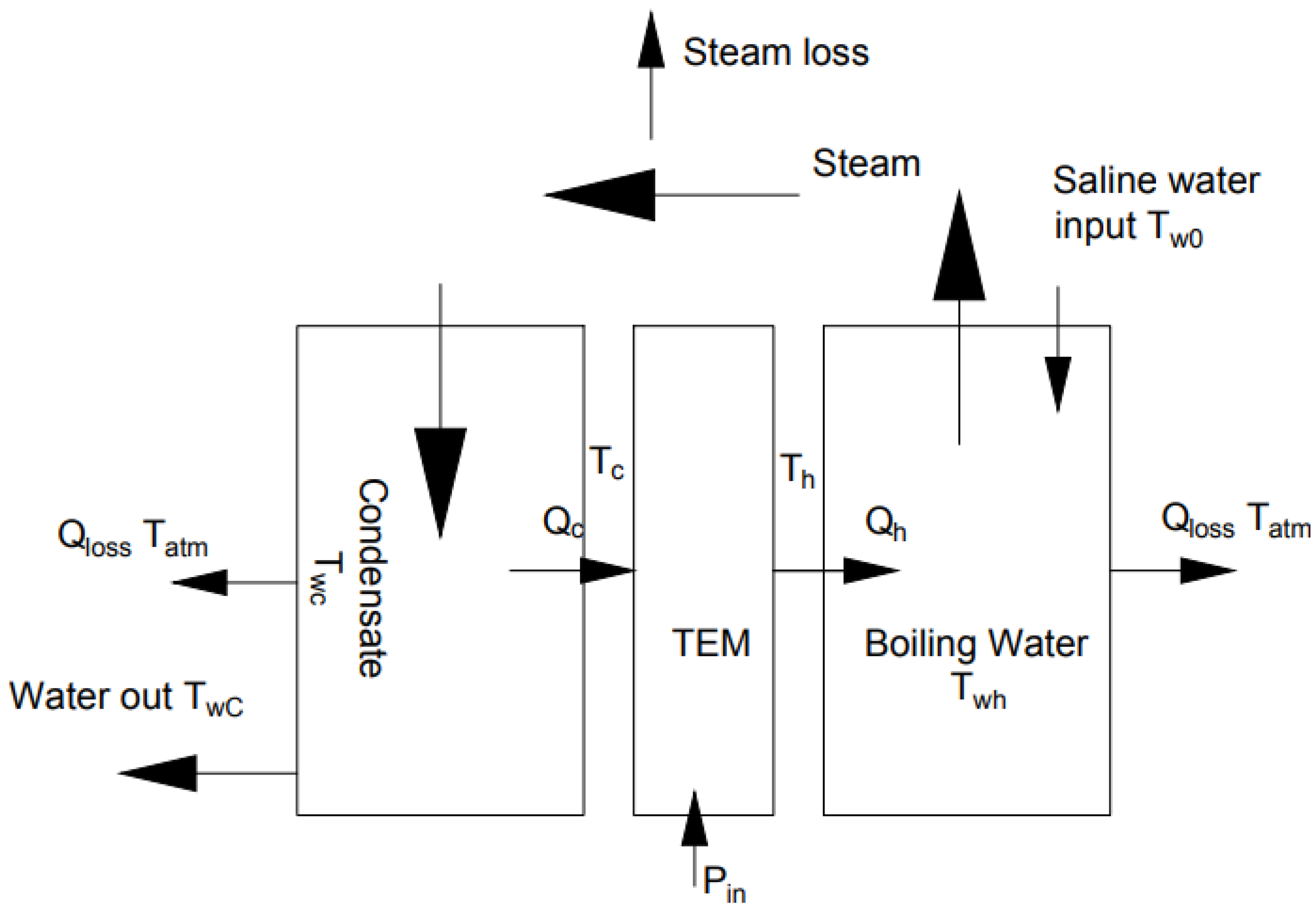
The TEMD hardware consists of the hot tank, cold tank, saline water tank, and cover. All of these are cast aluminum, except the saline tank, which is made from a 1.0 mm galvanized steel sheet. Aluminum has high thermal conductivity and can help to cool the cold tank. On the other side, insulation means are needed on the hot tank to reduce energy losses. Figure 3 shows the schematic diagram of the TEMD as an electrothermal system. The electrical components are 24 VDC power supply generated by a photovoltaic system, a 12 buck converter, 2 PWM drivers, two TEMs, and two thermocouples with a MAX 6675 interface. The Arduino Mega is used to control the process, and it is connected to a PC and programmed with Simulink and MATLAB. The data are collected by using Simulink software. The TEM input voltage is set constant at 14 VDC with the PID controller, and the MPC controller controls its value, as will be discussed in the next section. The fan voltage is the controller command in both PID and MPC controllers. The fan is used to cool the cold side of the TEMD.
3.2. Control Methodology
Previous work has tackled driving the thermoelectric distiller in open loop control [15]. This paper proposes two principal control methodologies: open loop and closed loop control. With an open loop, two cases are conducted, the first case is running the thermoelectric distiller without a cooling fan, and this case is like the previous work done in [15]. This open loop case showed that the vapor production rate is higher than the condensation rate; this main drawback led to increased vapor pressure in the distiller. The second open loop case has the cooling fan at full speed by setting the highest input voltage to the fan motor. In both open loop systems, the TEM’s voltage is set constant such that the PWM voltage source is set to 14 VDC. In the results section, these open loop cases will be compared with proposed closed loop methodologies.
The second principal methodology is a closed loop system. This paper proposes closed loop control to drive the thermoelectric based water distillation process and guarantee maximum productivity. This target can be achieved by keeping the system balanced by having the water evaporation rate equal to the water condensation rate, so that the vapor loss will be minimized, and, as a result, the lost energy will be minimized. Since the vapor production rate is more than the condensation rate, an external cooling device is needed to keep the system balanced. This work adds a fan and heat sink to the TEMD system. The fan will run to minimize the extra vapor produced and keep the system balanced at a high heat recovery state. It was realized that when the fan runs at full rotational speed, more heat will be removed from the system, which will decrease the recovered energy by TEM to the hot tank. At this point, using a fan at full rotational speed will drop the system efficiency. On the other hand, if the fan is stopped, more vapors will be accumulated, and the vapor will escape from the system vent having more energy loss (the open loop case). So, it should be an optimum operating point in the middle with a certain value of the fan speed with maximum productivity and minimized energy losses.
Three proposed closed loop strategies may possibly be used for obtaining maximum productivity, as follows:
- The first one is keeping a constant voltage for the TEM and controlling the fan rotational speed based on the pressure inside the system with no vapor vent. So, if the vapor production increases, the pressure will rise accordingly, and the controller will increase the fan speed to reduce the vapor and the pressure. This method was experimentally found to be difficult since the distiller vapor pressure value varies rapidly, and it requires to keep the system working at the equilibrium point by controlling the system’s input and output water flows. This control approach is similar to the steam power plant control system. Therefore, this method is not considered in this research.
- The second methodology considers the TEM cold side temperature as a feedback signal and the fan input voltage as a control command, while keeping the vent open with constant voltage at the TEM input. The controller’s response is simplified into two steps: 1—TEM cold side temperature increases, and more vapor will be generated in the TEMD. 2—Then the controller will increase the fan speed to condense more vapor and keep the system at a stable operating point, sustaining lower pressure and decreasing the vapor losses. Experimentally the TEM cold side temperature indicates the amount of vapor inside the system. However, the energy harvested from the vapor’s latent heat will decrease if the fan’s rotational speed is increased. A PID controller is implemented with this strategy and compared with the third one. The optimum value of the fan’s rotational speed will be discussed in the results section.
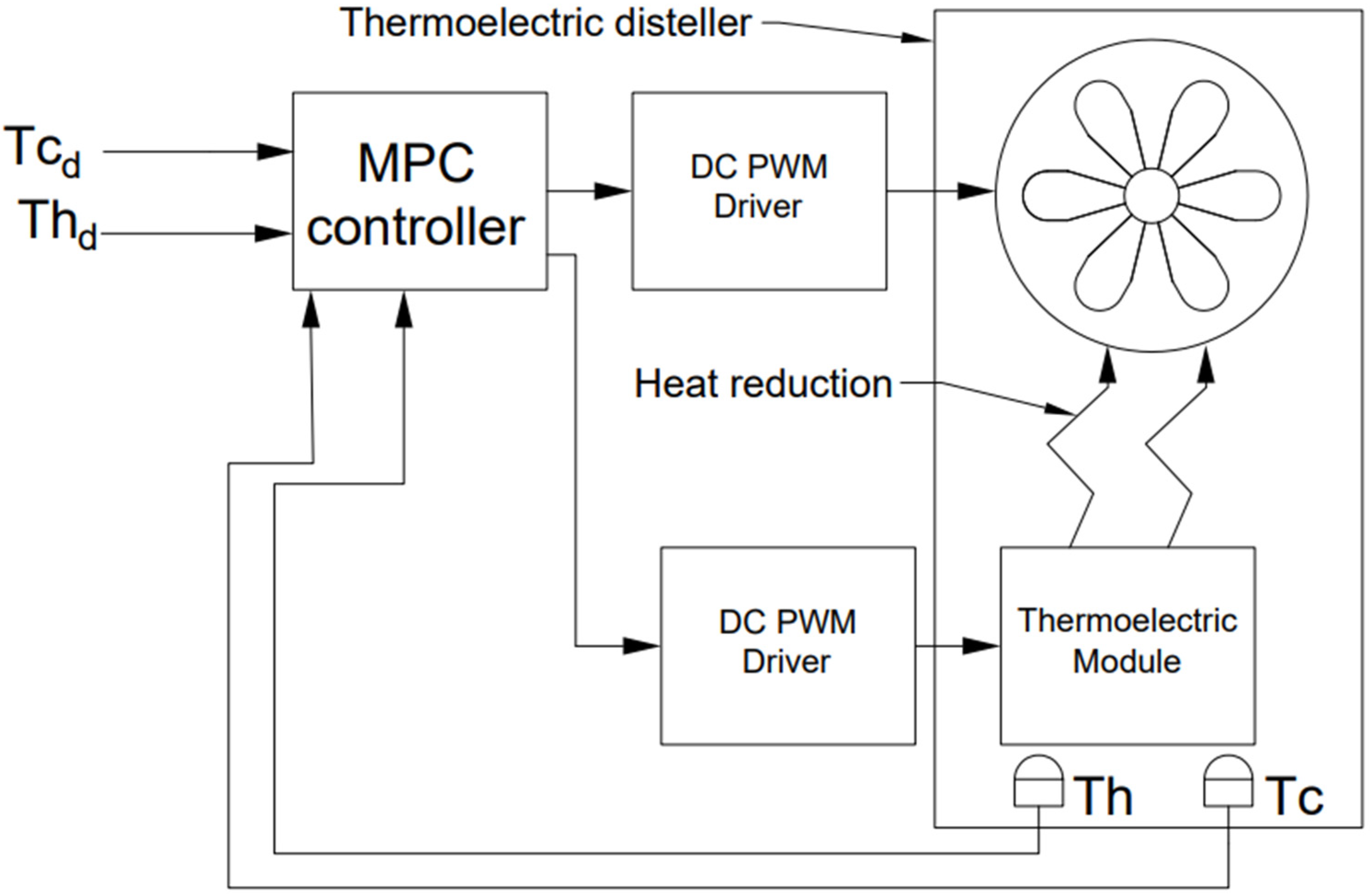
- The third control methodology considers more input signals and , compared with the second strategy, which uses only . The third strategy deals with two control commands: the fan and TEM voltages. So, the system will be a multi-input and multi-output system. The controller will drive the system using a well-known control method called Model Predictive Control (MPC). Using a predefined mathematical model, this method predicts the system’s behavior with the control commands. So, the controller will generate the optimum control commands that perform the best dynamic responses from studying the system’s mathematical model. This third method is implemented and compared with the second control methodology.
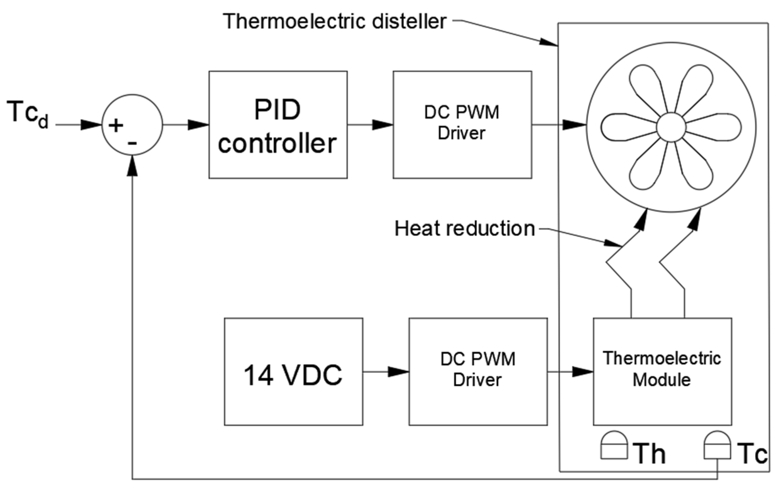
3.3. PID and MPC Control System Schematic Diagrams
Figure 4 shows the schematic diagram of the suggested control system with a PID Controller. The PID controller is a common and a famous controller type, where the error signal is derived as in Equation (17); then, the control command , current or voltage in our case, is calculated using Equation (18). Three terms are used in this controller (proportional, integral, and derivative terms), and three parameters (, , and ) have to be tuned appropriately. PID controller tuning can be implemented by software once the system’s mathematical model is given. The system model is found experimentally, and will be discussed in the following subsection. In the PID controller case, the distiller has two inputs: the TEM input voltage and the fan input voltage. The TEM voltage is set to be a constant. The PID controller manipulates the fan voltage to keep the at the desired value .
Figure 5 shows the schematic diagram of the suggested control system with the MPC controller. In the case of the MPC controller, the distiller has two inputs: the TEM input voltage and the fan input voltage. Temperature sensors send the feedback to the controller, and both of them are manipulated by the controller. The MPC controller is an optimal controller type [19]. MPC predicts the system dynamics for a finite length of time, called a prediction horizon. The system model is required and found experimentally, as will be discussed in the following subsection. Using the control command , MPC minimizes a quadratic cost function as shown in Equation (19).
where is the system state weight.
are the desired values, in our case and .
are the system states, in our case and .
are the weights of the control commands.
are the system control commands, in our case the TEM and fan voltages.
3.4. System Identification: MPC and PID Controller Tuning
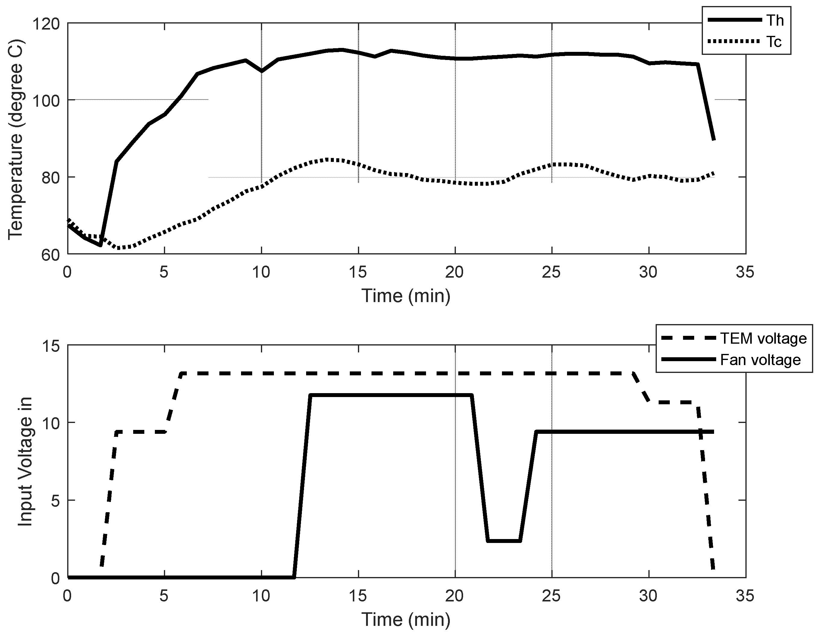
A properly identified TEMD model is crucial for tuning the PID and MPC controllers. TEMD model is complicated since the heat transfer coefficients are functions of steam pressure inside the system. One easy method to simplify this model is using MATLAB identification tools that give an approximated model around the operating points. The identification method starts with running the model in open loop and collecting the output values accordingly during a specific time interval. Since the TEMD system has two inputs (TEM voltage and fan voltage) and two outputs (Th and Tc), this control system can be considered a multi-input multi-output (MIMO) system. The curves of input voltages and output temperatures of this system are shown in Figure 6.
It is noted that, at the beginning when switching the system on, the Tc will decrease slightly due to the Seebeck effect. Then after a short time, Th will increase, and the Tc will increase accordingly while keeping a temperature difference.
These results are used in the identification toolbox in MATLAB with command N4SID to have the best approximated discrete state-space model in Equations (20) and (21). The identified model was found with sample time equaling 1 s and A, B, C, and D matrices as shown below. The identified model is a 95% fit with a final prediction error (FPE) of 0.01427 and a mean squared Error (MSE) of 0.2683. These values indicate that this model is accepted.
where and .
The values of tuning parameters for PID controller are found to be , , and . The PID controller has a limited range of voltage equal [0–12] VDC with the clamping anti-wind up method. In addition, this model is fed into the MPC toolbox in MATLAB.
4. Experimental Results
This section discusses the results of the open loop and closed loop control strategies, suggests optimal operating conditions found experimentally, and compares the experimental results of the closed loop strategies (PID and MPC), including the system dynamics with both PID and MPC controllers.
4.1. Open Loop Experimental Results
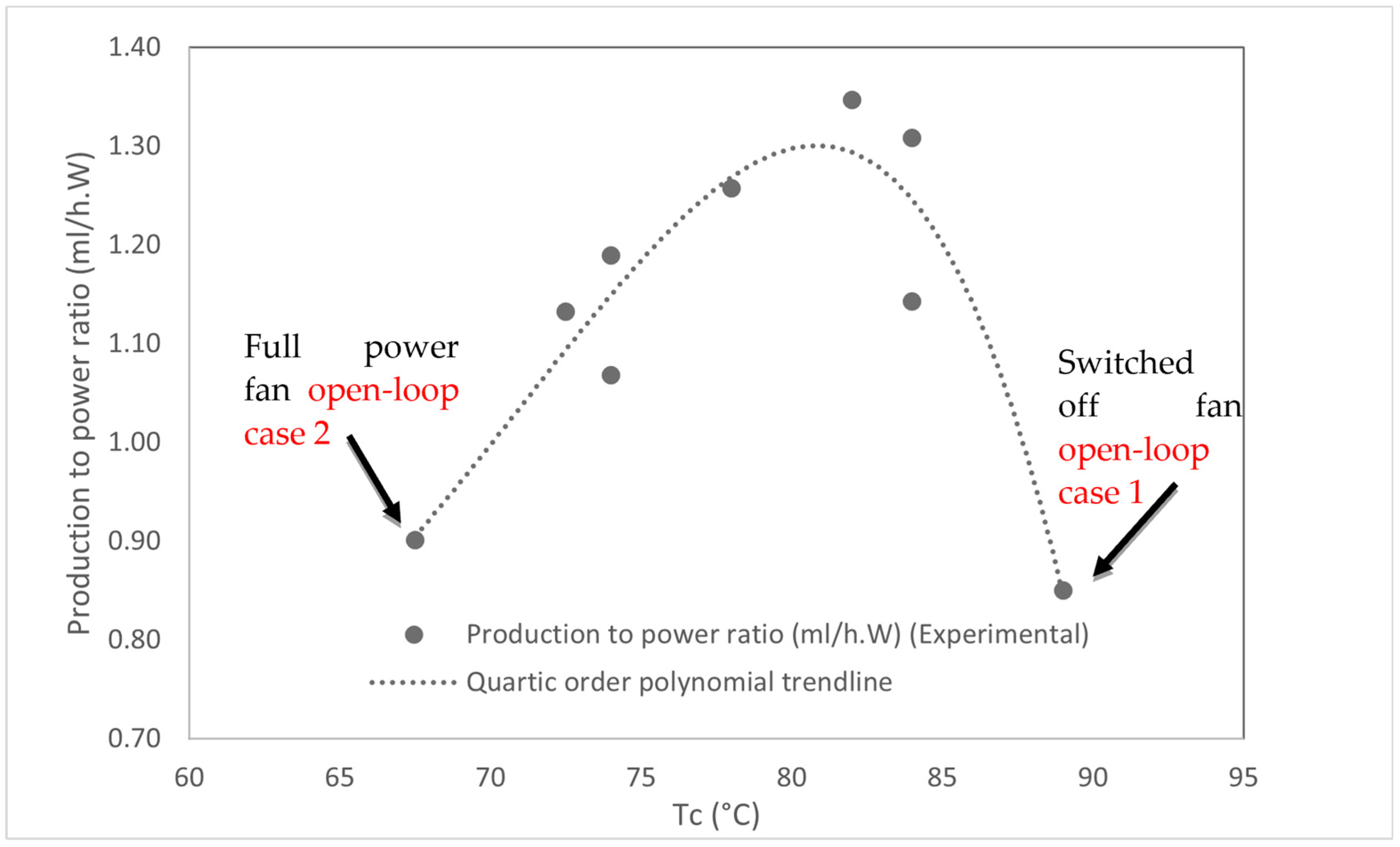
Two open loop cases were discussed in previous sections; the first case is running the distiller without a cooling fan, and the experimental results show system productivity equal to 120 mL/h of purified water. The results of the second open loop case with maximum fan speed show 125 mL/h purified water productivity. Both cases have approximately low production rates and low productivity to power ratios, as shown in Table 1. The explanation for this decrease in productivity is due to water loss in the vent in case 1, and the increase of energy loss with the fan in case 2. For more details, refer to Section 3.2.
4.2. Closed Loop Optimum Operating Conditions
The approach used in this paper is to find the optimal operating point experimentally and then compare the two proposed closed loop control strategies. Consequently, many experimental tests were performed to find the relation between the system productivity and operating conditions and . Table 1 shows the experimental results with different set points. Compared to previous work [14], the productivity to power ratio is decreased because of the heat loss in the electronic devices and PWM drivers. That causes transistors to consume extra heat loss due to the high frequency switching with the PWM method.
The productivity to power ratio varies with respect to as shown in Figure 7. The best production to power ratio is at set point . mainly depends on the hot water temperature in the hot tank, and since it is constant (equal to 98 ), there are no major changes in . The behavior of the system can be illustrated as follows: low Tc id caused by the high cooling from the fan, so the system will lose more energy and the evaporation rate will decrease. On the other hand, high Tc means low cooling from the fan; the vapor will accumulate due to the weakened condensation rate, and then vapor losses will increase via the vent, which will reduce productivity. As shown in Table 1, the optimum production to power ratio is at Tc = 82 ℃, which is 150% more compared to open loop operating conditions: (1) fan switched off and (2) full fan power.
In summary, water productivity in the proposed operating conditions with closed loop control is higher than the value of the open loop thermoelectric distiller. This shows that the control of the TEM cold side temperature plays an important role in thermoelectric efficiency and productivity. The resultant specific energy consumption (SEC) at the max productivity is equal to 742 . Note that the best operating conditions found experimentally are not fixed, and they may vary if the distiller design changes. The max productivity rate to power ratio is 1.35 mL/(W·h) compared with 0.49 mL/(W·h) by previous thermoelectric based distiller proposed in [13].
4.3. Testing PID Controller
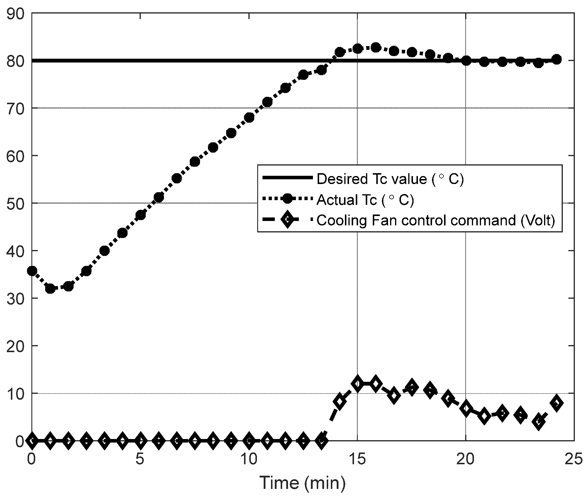
The PID controller is added to the system then the system is closed loop operated. Figure 8 shows the system response with the proposed PID controller, where the settling time is 20 min. This controller is used to regulate the system in the desired operating conditions, in this case keeping at .
4.4. Comparing PID with MPC Controllers
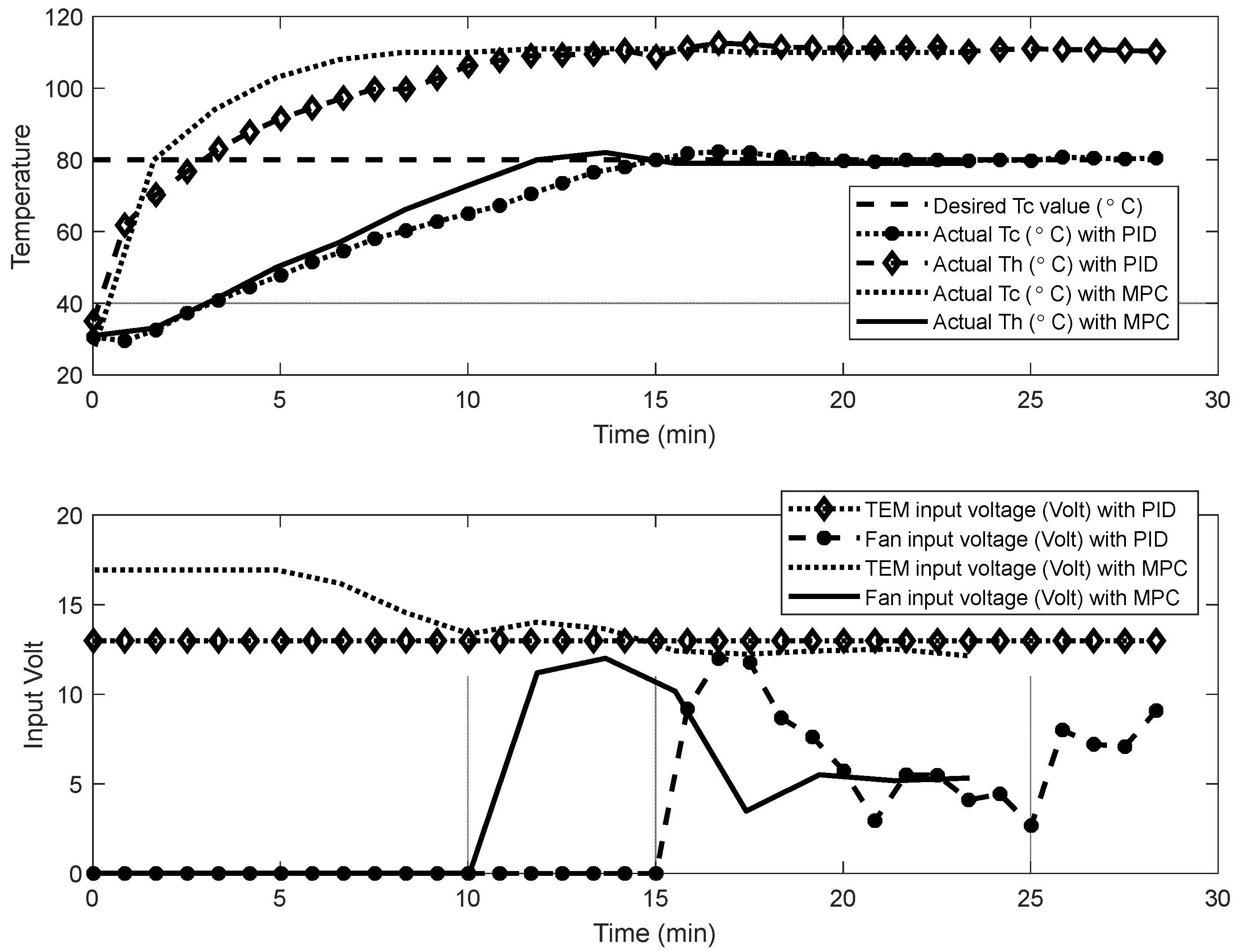
The model predictive controller (MPC) is a multi-input and multi-output controller that can, in this case, send two control commands: the TEM input voltage and fan input voltage for regulating the two outputs, and values. This control approach is compared with the well-tuned PID controller, and the results were found as shown in Figure 9. The MPC shows faster system performance with less settling time. This result was expected since the MPC controller controls the TEM voltage and the fan speed, compared with only controlling the fan speed with PID controller.
The operating conditions of the modified design were determined experimentally by studying the effect of varying the cold and hot side temperatures on the system’s productivity. Two control methodologies were proposed, PID and MPC, and both strategies were used to keep the system working at specified operating conditions. First, the system model around the operating point is determined experimentally, and then the PID and the MPC controllers are adjusted based on this model. The effect of the added design modifications on the thermoelectric distiller design is clear. The total collected distilled water during 20 min from the previous design thermoelectric distiller was 0.85 mL/(W·h) [13], and the total collected distilled water from the modified thermoelectric distiller was 1.35 mL/(W·h). The MPC controller leads to better dynamic performance than the PID controller.
5. Conclusions
The performance of a novel design of a thermoelectric distiller is investigated. The design modifications include the addition of an inclined cover of the thermoelectric module, a heat sink with a controlled cooling fan, using two feedback control systems with PID and MPC controllers, and the suggestion of a special control strategy to handle various disturbances and variables to keep the system in a steady state at the desired operating conditions. Different operating conditions are investigated to find the best performance with the highest pure water productivity. In this work, the mathematical model of the proposed distiller is derived. A comparison between PID and MPC controllers with different operating conditions is conducted. The system with the MPC controller has better dynamic performance than the system with PID controller. Experimentation results show that a thermoelectric module with the proposed design and operating conditions, for both cases with MPC and PID controllers, increase productivity by up to 150%, compared with the open loop thermoelectric distiller. This increase is obtained at the optimum operating conditions because of increasing the heat recovery and vapor productivity and decreasing the vapor loss in the vent. The results show higher productivity with less water losses compared with previous thermoelectric distillers.
Author Contributions
The study conception and design were performed by M.T.N., D.A. and S.A. contributed to the study conception and design. The controller design was performed by M.T.N., and data collection and analysis were performed by M.T.N. and D.A. The first draft of the manuscript was written by M.T.N. All authors have read and agreed to the published version of the manuscript.
Funding
The work is part of a funded project at Applied Science Private University with number DRGS-2021-2022-2.
Data Availability Statement
All data are provided in the manuscript in the form of tables or figures.
Acknowledgments
The authors are grateful to Applied Science Private University, Amman, Jordan for the full financial support granted to this research project.
Conflicts of Interest
The authors declare no conflict of interest.
Nomenclature
| Symbol | Description |
| The Seebeck effect coefficient (V/K) | |
| The heat capacity of the water (kJ/(kg·K)) | |
| COPh | Coefficient of performance for heating process in the TEM |
| COPc | Coefficient of performance for cooling process in the TEM |
| Enthalpy of the vapor (kJ/kg) | |
| Enthalpy of the output water at 45 (kJ/kg) | |
| The latent heat of the boiled water (kJ/kg) | |
| Enthalpy of the inlet water at 25 (kJ/kg) | |
| The TEM inlet current. | |
| PID controller proportional gain | |
| PID controller derivative gain | |
| PID controller integral gain | |
| Thermal conductivity of the TEM (W/K) | |
| The mass flow rate of the inlet water. | |
| The mass flow rate of the produced vapor | |
| The mass flow rate of the produced water (condensation) | |
| The total water mass in the hot tank | |
| Vapor loss flow rate outside the tanks from the vent | |
| The number of TEM connected in parallel | |
| The electrical power consumed by the TEMD | |
| Electrical power input to TEMs (W) | |
| Heat flux of the TEM cold side (W) | |
| Heat flux of the TEM hot side (W) | |
| Heat losses from the hot or the cold tank to surroundings | |
| Thermal resistance between the TEM cold side and the vapor (K/W) | |
| Thermal resistance between the TEM hot side and the hot tank water (K/W) | |
| The TEM electrical resistance | |
| The thermal resistance between the system and the environment (K/W) | |
| Hot water density | |
| Condensate water density | |
| TEM hot side temperature | |
| TEM cold side temperature | |
| Temperature of the water in the hot tank | |
| Temperature of the vapor | |
| Temperature of the water in the cold tank | |
| Temperature of the surrounded environment (25 ) | |
| Total dissolved solids | |
| The voltage source value | |
| Condensate water drops covers inside of the cold tank wall. | |
| Hot water volume inside of the hot tank. |
Abbreviations
| Symbol | Description |
| A | Amber |
| Degree Celsius | |
| MPC | Model predictive controller |
| MIMO | Multi-input multi-output system |
| PID | Proportional integral derivative controller |
| PWM | Pulse-width modulation |
| ppm | Part per million |
| TEM | Thermoelectric module |
| TDS | Total dissolved solids |
| TEMD | Thermoelectric module-based distiller |
| VDC | DC voltage |
References
- Abou Assi, R.; Ng, T.F.; Tang, J.R.; Hassan, M.S.; Chan, S.Y. Statistical Analysis of Green Laboratory Practice Survey: Conservation on Non-Distilled Water from Distillation Process. Water 2021, 13, 2018. [Google Scholar] [CrossRef]
- Al-Karaghouli, A.; Kazmerski, L.L. Energy Consumption and Water Production Cost of Conventional and Renewable-Energy-Powered Desalination Processes. Renew. Sustain. Energy Rev. 2013, 24, 343–356. [Google Scholar] [CrossRef]
- Al-Nimr, M.A.; Al-Ammari, W.A. A Novel Hybrid and Interactive Solar System Consists of Stirling Engine vacuum Evaporator thermoelectric Cooler for Electricity Generation and Water Distillation. Renew. Energy 2020, 153, 1053–1066. [Google Scholar] [CrossRef]
- Parsa, S.M.; Rahbar, A.; Koleini, M.H.; Aberoumand, S.; Afrand, M.; Amidpour, M. A Renewable Energy-Driven Thermoelectric-Utilized Solar Still with External Condenser Loaded by Silver/Nanofluid for Simultaneously Water Disinfection and Desalination. Desalination 2020, 480, 114354. [Google Scholar] [CrossRef]
- Das, D.; Bordoloi, U.; Kalita, P.; Boehm, R.; Kamble, A. Solar Still Distillate Enhancement Techniques and Recent Developments. Groundw. Sustain. Dev. 2020, 10, 100360. [Google Scholar] [CrossRef]
- Alwan, N.; Ahmed, A.; Majeed, M.; Shcheklein, S.; Yaqoob, S.; Nayyar, A.; Nam, Y.; Abouhawwash, M. Enhancement of the Evaporation and Condensation Processes of a Solar Still with an Ultrasound Cotton Tent and a Thermoelectric Cooling Chamber. Electronics 2022, 11, 284. [Google Scholar] [CrossRef]
- Al-Nimr, M.A.; Qananba, K.S. A Solar Hybrid Thermoelectric Generator and Distillation System. Int. J. Green Energy 2018, 15, 473–488. [Google Scholar] [CrossRef]
- Stout, B.; Peebles, R. High Temperature Peltier Effect Water Distiller. U.S. Patent 6,893,540, 17 May 2005. [Google Scholar]
- Milton, M. Peltier Effect Concentric Still. U.S. Patent 3,393,130, 16 July 1968. [Google Scholar]
- Trusch, R.B. Thermoelectric Integrated Membrane Evaporation System. U.S. Patent 4,316,774, 23 February 1982. [Google Scholar]
- Samsonov, N.M.; Bobe, L.S.; Rifert, V.G.; Barabash, P.A.; Komolov, V.V.; Margulis, V.I.; Novikov, V.M.; Pinsky, B.Y.; Protasov, N.N.; Rakov, V.V.; et al. System and a Rotary Vacuum Distiller for Water Recovery from Aqueous Solutions, Preferably from Urine Aboard Spacecraft. U.S. Patent 6,258,215, 10 July 2001. [Google Scholar]
- Shoeibi, S.; Rahbar, N.; Esfahlani, A.A.; Kargarsharifabad, H. Application of Simultaneous Thermoelectric Cooling and Heating to Improve the Performance of a Solar Still: An Experimental Study and Exergy Analysis. Appl. Energy 2020, 263, 114581. [Google Scholar] [CrossRef]
- Al-Madhhachi, H. Solar Powered Thermoelectric Distillation System. Ph.D Thesis, Cardiff University, Cardiff, UK, 2017. [Google Scholar]
- Al-Madhhachi, H.; Phillips, M.; Gao, M. Validation of Vapour/Water Production in a Thermoelectric Distillation System; Avestia Publishing: Ottawa, ON, Canada, 2017; p. 117-1. [Google Scholar]
- Nasir, M.T.; Afaneh, D.; Abdallah, S. High Productivity Thermoelectric Based Distiller. Desalination Water Treat. 2020, 206, 125–132. [Google Scholar] [CrossRef]
- Sasongko, S.B.; Sanyoto, G.J.; Buchori, L. Study of Performance: An Improved Distillation Using Thermoelectric Modules. Chem. Eng. Trans. 2021, 89, 649–654. [Google Scholar]
- Khanmohammadi, S.; Chaghakaboodi, H.A.; Musharavati, F. A New Design of Solar Tower System Amplified with a Thermoelectric Unit to Produce Distilled Water and Power. Appl. Therm. Eng. 2021, 197, 117406. [Google Scholar] [CrossRef]
- Snyder, G.J.; Ursell, T.S. Thermoelectric Efficiency and Compatibility. Phys. Rev. Lett. 2003, 91, 148301. [Google Scholar] [CrossRef] [PubMed] [Green Version]
- Mayne, D.Q.; Rawlings, J.B.; Rao, C.V.; Scokaert, P.O. Constrained Model Predictive Control: Stability and Optimality. Automatica 2000, 36, 789–814. [Google Scholar] [CrossRef]
Figure 1.
(a) TEMD schematic diagram. (b) TEMD experimental setup.


Figure 2.
The thermal model diagram of TEMD.

Figure 3.
Control schematic diagram of TEMD.

Figure 4.
Schematic diagram of the system with PID Controller.

Figure 5.
The schematic diagram of the system with MPC controller.

Figure 6.
The open loop system temperature responses based on the manually adjusted input voltages.

Figure 7.
The system’s production to power ratio with different Tc values and constant TEM voltage = 14 VDC.
Figure 7.
The system’s production to power ratio with different Tc values and constant TEM voltage = 14 VDC.

Figure 8.
The system response with the proposed PID controller.

Figure 9.
TEMD dynamic performance with the PID and MPC controllers.


Table 1.
Experimental results.
| TEM PWM Voltage (Volt) | 24VDC Power Supply Current (Amp) | TEM Power (Watt) | TDS (ppm) | Th (°C) | Tc (°C) | Productivity (ml/h) | Production to Power Ratio (ml/(W·h)) | Fan Operation |
|---|---|---|---|---|---|---|---|---|
| (Set Point for Controlled Cases) | ||||||||
| 14.2 | 5.78 | 138.72 | 54 | 110 | 67.5 * | 125 | 0.9 | Full power (open loop case 2) |
| 14 | 5.81 | 139.44 | 62 | 111 | 72.5 | 157.9 | 1.13 | by closed loop feedback controller |
| 14 | 5.85 | 140.4 | 68 | 111 | 74 | 150 | 1.07 | |
| 14 | 5.84 | 140.16 | 70 | 111 | 74 | 166.7 | 1.19 | |
| 14 | 5.85 | 140.4 | 74 | 111.5 | 78 | 176.5 | 1.26 | |
| 14 | 5.8 | 139.2 | 75 | 112.3 | 82 | 187.5 | 1.35 | |
| 14 | 6.08 | 145.92 | 83 | 112 | 84 | 166.7 | 1.14 | |
| 14 | 5.97 | 143.28 | 115 | 111 | 84 | 187.5 | 1.31 | |
| 14 | 5.88 | 141.12 | 180 | 112 | 89 * | 120 | 0.85 | Off (open loop case 1) |
* Without control (open loop).
Publisher’s Note: MDPI stays neutral with regard to jurisdictional claims in published maps and institutional affiliations. |
© 2022 by the authors. Licensee MDPI, Basel, Switzerland. This article is an open access article distributed under the terms and conditions of the Creative Commons Attribution (CC BY) license (https://creativecommons.org/licenses/by/4.0/).
Share and Cite
MDPI and ACS Style
Nasir, M.T.; Afaneh, D.; Abdallah, S. Design Modifications for a Thermoelectric Distiller with Feedback Control. Energies 2022, 15, 9612. https://0-doi-org.brum.beds.ac.uk/10.3390/en15249612
AMA Style
Nasir MT, Afaneh D, Abdallah S. Design Modifications for a Thermoelectric Distiller with Feedback Control. Energies. 2022; 15(24):9612. https://0-doi-org.brum.beds.ac.uk/10.3390/en15249612
Chicago/Turabian StyleNasir, Mohammad Tariq, Diaa Afaneh, and Salah Abdallah. 2022. "Design Modifications for a Thermoelectric Distiller with Feedback Control" Energies 15, no. 24: 9612. https://0-doi-org.brum.beds.ac.uk/10.3390/en15249612
Note that from the first issue of 2016, this journal uses article numbers instead of page numbers. See further details here.