
Employing the Peltier Effect to Control Motor Operating Temperatures

1
UniSA STEM, University of South Australia, Mawson Lakes, SA 5095, Australia
2
Lucas Solutions Pty. Ltd., Hazelwood North, VIC 3840, Australia
3
Joint and Operations Analysis Division, Defence Science and Technology Group, Melbourne, VIC 3207, Australia
*
Author to whom correspondence should be addressed.
Energies 2023, 16(5), 2498; https://0-doi-org.brum.beds.ac.uk/10.3390/en16052498
Submission received: 24 January 2023
/
Revised: 27 February 2023
/
Accepted: 4 March 2023
/
Published: 6 March 2023
(This article belongs to the Special Issue Advanced Studies of Thermoelectric Systems)
Abstract
:Electrical insulation failure is the most common failure mechanism in electrical machines (motors and generators). High temperatures and/or temperature gradients (HTTG) are the main drivers of insulation failure in electrical machines. HTTG combine with and augment other destructive effects from over-voltage, to voltage transients, overload and load variations, poor construction techniques, and thermal cycling. These operating conditions cause insulation damage that leads to electrical insulation failure. The insulation failure process is greatly accelerated by pollutants and moisture absorption. A simple and robust way to reduce HTTG and moisture adsorption is by maintaining constant internal temperatures. The current method to maintain elevated internal temperatures and reduce condensation issues is by internal electrical heating elements. This paper examines the effectiveness of applying thermoelectric coolers (TECs), solid-state heat pumps (Peltier devices), as heaters to raise a motor’s internal temperature by pumping heat into the motor core rather than heating the internal air. TEC technology is relatively new, and the application of TECs to heat a motor’s internal volume has not previously been explored. In this paper, we explore the hypothesis that TECs can pump heat into a motor when out of service, reducing the HTTG by maintaining high winding slot temperatures and eliminating condensation issues. This paper describes a test motor setup with simple resistive heating (traditional method), compared with the application of TECs with heat sinks, heat pipes, and a water circulation heat exchanger, to gauge the capability of TECs to heat the inner core or winding area. In this paper, we demonstrate the full integration of TECs into a motor. The results show that each of the systems incorporating the TECs would effectively pump heat into the core and keep the winding hot, eliminating condensation issues and water ingress due to thermal cycling.
1. Introduction
Electrical motors are now incorporated into every facet of today’s life and primarily convert electrical energy to mechanical energy. Their makeup consists of steel cores with insulated electrical windings, bearings, rotors, and couplings. A key material affecting the life of a motor is the electrical insulation. The electrical insulating material applied to the winding conductors used in electrical motors varies from simple enamel coatings to layers of glass/mica tape impregnated with resins. It can also consist of layers of specialized insulating material such as Nomex or Kapton. The type of insulation and the number of layers applied depend on the operating voltages and thermal conditions. The more exotic the material, the higher the costs. Its purpose is to insulate the turn conductors from each other and from the core. All insulation systems are susceptible to mechanical and thermal damage [1], and their ability to maintain their insulating property can be greatly affected by pollutants such as dirt, oil, and moisture [2].
The insulation system for small motors up to 300 kW is primarily made from enamel resins, and for large motors, a resin-impregnated fibreglass carrier with mica is normally used. When motors are in service, this insulation is affected by several operating conditions. High temperatures (HT) and temperature gradients (TG) are key issues affecting insulation integrity, but normal operating conditions such as thermal cycling, load variations, voltage fluctuations, system harmonics, and daily environmental temperature changes cause insulation aging. For motors greater than 50 kW, the air gap flow heating phenomena [3] also affect insulation life. Normal maximum running temperatures by design are set by the class of insulation used. If temperatures exceed the class temperature by 10 C, the insulation life will be halved. Variations in the operation temperature result in varying dimensional changes to the windings, insulation, core, and wedging systems. The mechanical stresses on the insulation due to different thermal expansion rates damage the insulation and result in surface damage and microcracking of the insulation [4,5]. This then enables moisture absorption and higher leakage currents [6].
New motors with new windings and insulation are nearly waterproof, as the insulation systems have little surface damage and absorb little moisture. Motors that have been in service for a long time are extremely hygroscopic [7,8], and a day of high humidity can result in an extremely low insulation resistance (IR) value [9]. Electrically testing a winding’s IR will show the serviceability of the insulation. Standards give a minimum IR value of , where E is the line voltage in kV [10].
When motors or generators are in service, they are hot, and moisture issues are rare [11]. Motors that are continually running for long periods of time suffer less from mechanical stresses, as the operational temperatures are more stable, compared to motors that are frequently started and stopped. Base-load hydro generators are good examples of electrical winding with long lives. Pumps or pressurising systems are good examples of motors that have short lives.
In all cases, as the insulation ages, electrical insulation systems become more susceptible to moisture ingress and failure [8,12]. Even motors stored for future use suffer from moisture ingress due to normal daily thermal cycling [13]. When internal air heats, it expands, causing it to bleed out of the motor. When it cools and contracts, it pulls air in with moisture from outside. Continued thermal cycling concentrates the internal moisture levels. This process affects in-service motors as well as motors stored as spares for operational backup. Over time, this daily thermal cycling can result in many litres of water being trapped inside the motor.
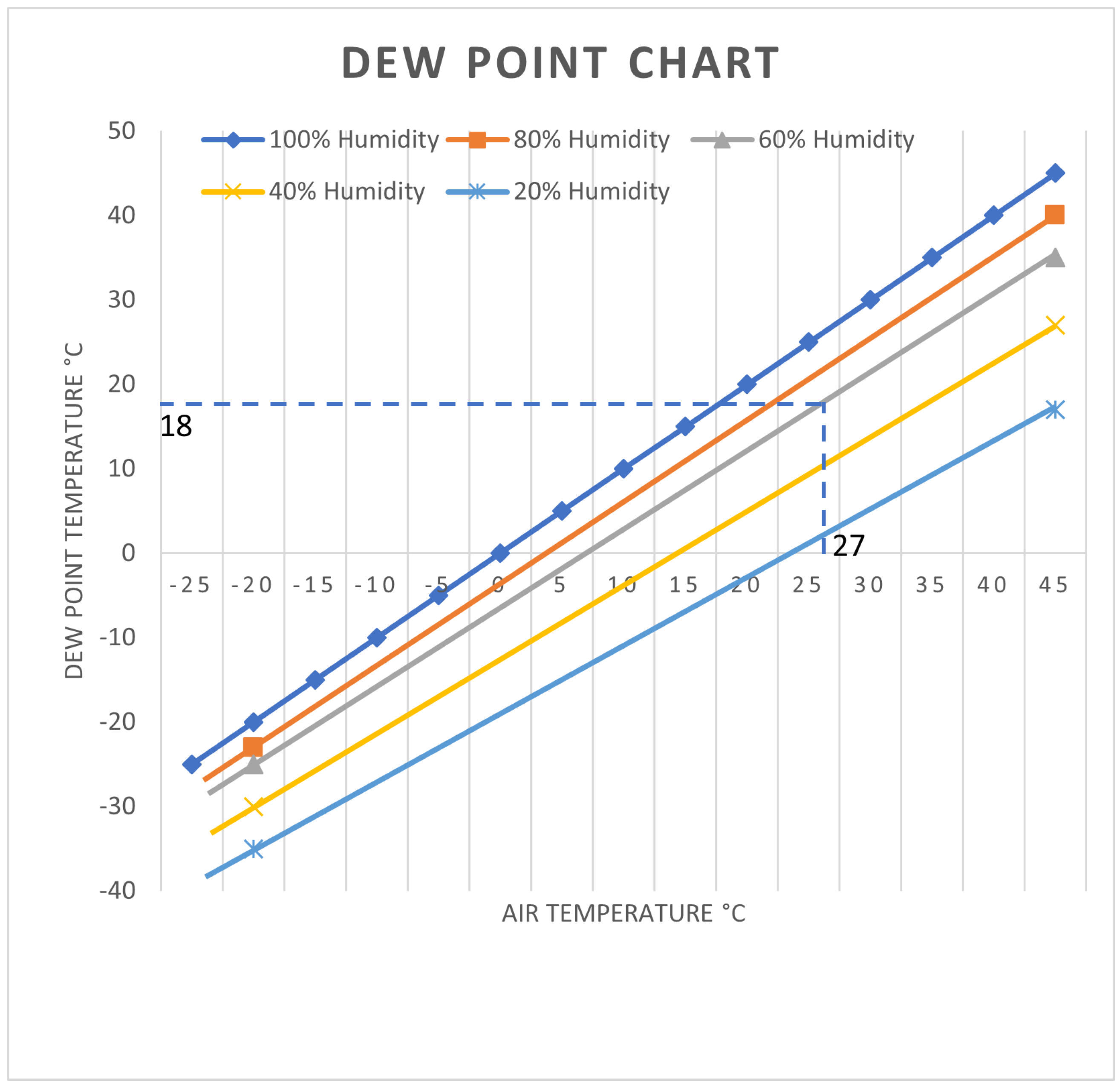
Because of the design of a motor, there is a large amount of iron in the stator and rotor cores, and they also have substantial frames. Consequently, a large mass results in a time delay in temperature stabilization with the external environment. The resulting temperature difference can result in internal condensation with the internal surfaces becoming wet and the electrical insulation absorbing high levels of moisture [8]. This high level of moisture contamination can lead to catastrophic insulation failure [14]. With hot days, cool nights, and the thermal inertia inside the machine, condensation is an issue. The point where moisture in the internal air will condense onto surfaces [15,16] or above daily temperatures [17] is called the dew point. As shown in Figure 1 [2], with an air temperature of 27 C and a humidity of 60%, the dew point is 18 C, and at 80% humidity, the dew point is 23 C. In normal conditions with cold nights and the air temperatures quickly rising when the sun rises, the conditions for internal condensation are easily reached, and internal heaters often fail to prevent internal condensation.
The degree of protection required and the practical systems to maintain motors above the dew point are dependent on a number of factors. Of immediate consideration is whether the motor is cycling in and out of service or whether it is being stored from the short- to the long term. If it is being stored, the environmental conditions become very important with internal temperature-controlled warehouses being far more protective than outside storage. To help eliminate internal condensation and moisture absorption, the internals of a motor need to be kept above the dew point [7]. The most common method employed to achieve this is the installation of resistive heaters mounted internally. Another system of heating heats the winding by circulating a low current via electronic supplies [7].
For storage, portable electric heaters inside a storage container, or for large machines, temporarily installed space heaters can be used [13]. Partial disassembly of the motor eliminates an internal environment that can result in condensation [17]. The use of waterproof bagging with several bags of desiccant (silica gel) can also be used [17]. Another option is called cocooning, sometimes used by the military, where the motor is protected and then covered with a layer of plastic sheeting; then, a continuous layer of plastic film is sprayed directly onto the motor surface [17]. Moreover, the process of slowly raising the motor temperatures while circulating dry air can remove upper level moisture contamination [18] before placing the motor back into service.
The heating methods currently employed, as described above, have difficulty in keeping motors above the dew point [2]. The resistive heaters commonly used are limited because they heat the internal air and have difficulty coping with rapid external temperature changes. Winding heating systems require extra equipment that adds to the installation and maintenance costs and is rarely applied. The cocooning option used by the military is for extreme conditions, and when in place, it is regularly renewed, increasing maintenance costs. Storage systems try to limit thermal cycling, but this is difficult to achieve.
This research investigates the application of thermoelectric coolers (TECs) to heat a motor to decrease the thermal gradients and stresses, eliminate the internal condensation issues, and stop the water absorption. The TEC module is a solid-state heat pump, and the direction the heat is pumped depends on the supply polarity applied to the module. The aim of this study is to set the TEC up to pump heat into the core to determine whether the inner core temperatures at the winding position can be controlled, providing the opportunity to keep the winding and internals hot. The TECs were incorporated into three basic systems to measure their impact on the heating system. This would help to control the condensation issues and reduce the thermal cycling stresses on the insulation and bracing systems. It is not a comparison between systems, as the system configuration requirements are dependent on the load and the environmental conditions and are different for each motor system. Any system that can improve the life of a motor and reduce the life cycle costs is worth exploring. The introduction of new technology often leads to additional environmental problems [19], but the introduction of the TEC and the ability to directly pump heat into the core will reduce the temperature differences, reducing the mechanical stresses and moisture issues without impacting other systems.
This research used a standard electrical motor integrated with sensors to monitor the temperatures at various locations using TECs to control the internal temperatures. The use of TECs to control internal temperatures has not been previously tried, and this was the first attempt to incorporate these low-cost devices into a fully instrumented motor working in standard operating conditions to improve the reliability and reduce the life cycle cost.
Section 2 explains the TEC devices available and their performance. Section 3 describes the test motor and each of the four heating setups (resistors, heat sinks, heat pipes, and a water heat exchanger) with the results from the four heating systems. Section 4 discusses the obtained results, and Section 5 concludes with the findings of the study.
2. Thermoelectric Cooling Device (Peltier Module)
The makeup of a thermoelectric cooling device is a combination of N and P type material between two ceramic plates. The most common and economical material is bismuth telluride (BiTe) or lead telluride (PbTe). These are low temperature materials that limit the operating range of the TEC. However, the base materials can be alloyed with other materials to improve the performance at various temperatures [20]. Thus, by alloying the base materials with other materials, the temperature ranges can be significantly increased to match the application.
The expected life of these units is 200,000 h, but care must be taken to not exceed the maximum ratings. There are also a variety of these units; for example, the TEC1-12715 (A$6.08) is rated for a maximum temperature of 70 C, and the TEC1-12715HTS (A$33.58) has a rating of 200 C. The cost increases in proportion to the increased temperature range.
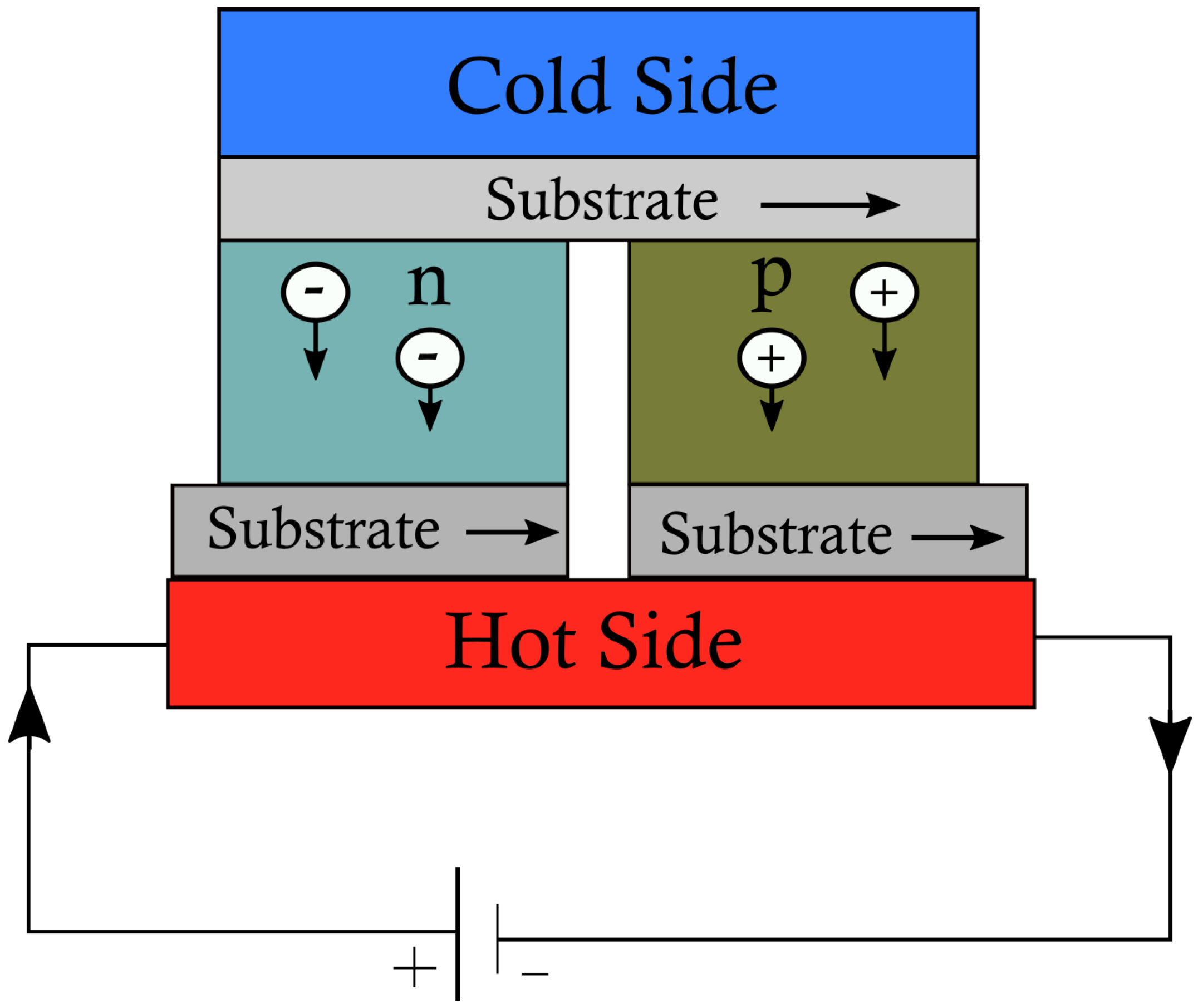
When a current passes through the TEC, heat is transferred from one plate to the other, as shown in Figure 2, and energy is pumped from one plate to the opposite plate. Today, these modules can be found in portable water coolers or heated seats in the car industry. Figure 2 shows a schematic diagram [21], and Figure 3 provides a view of the internal constructional layout.
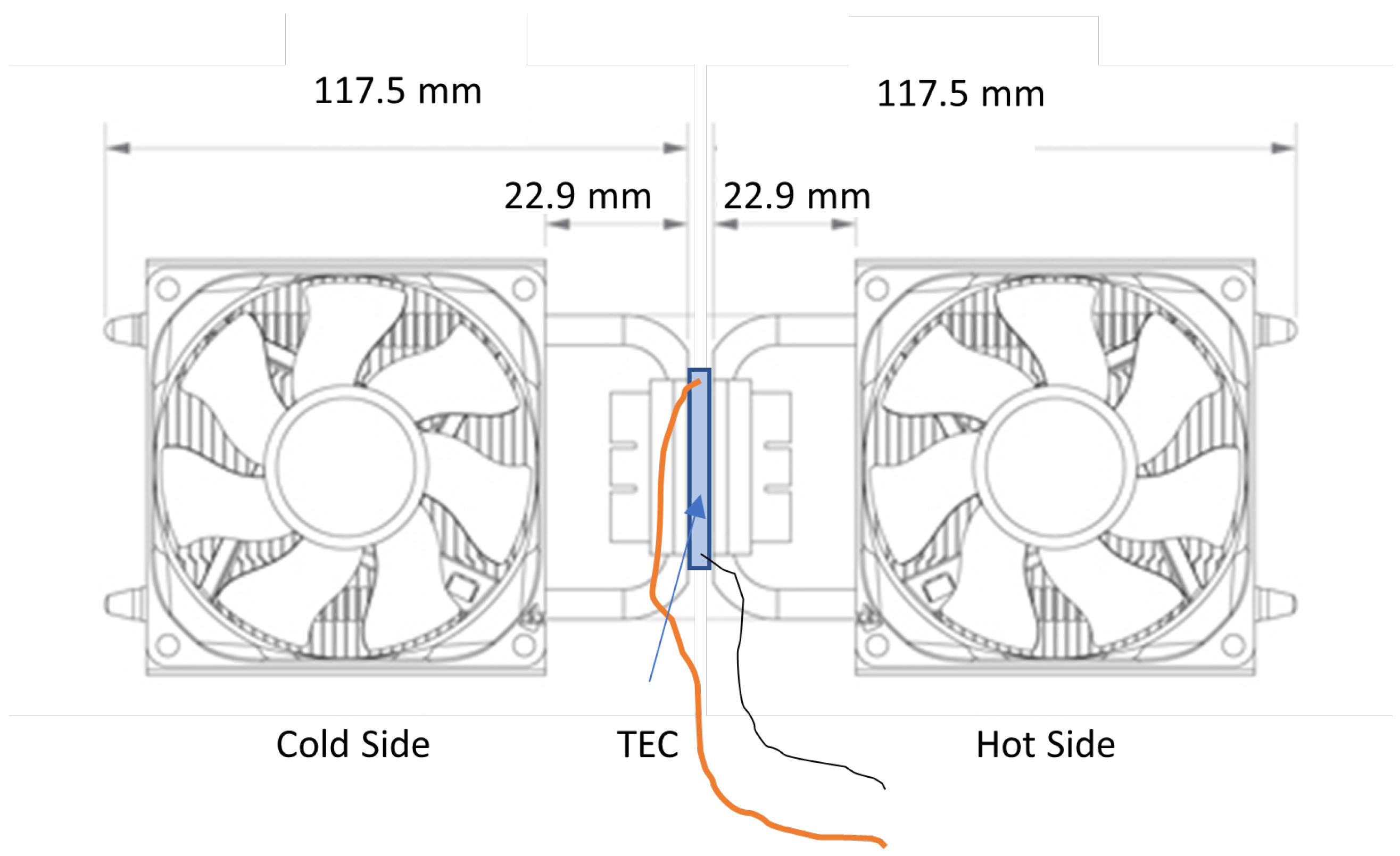
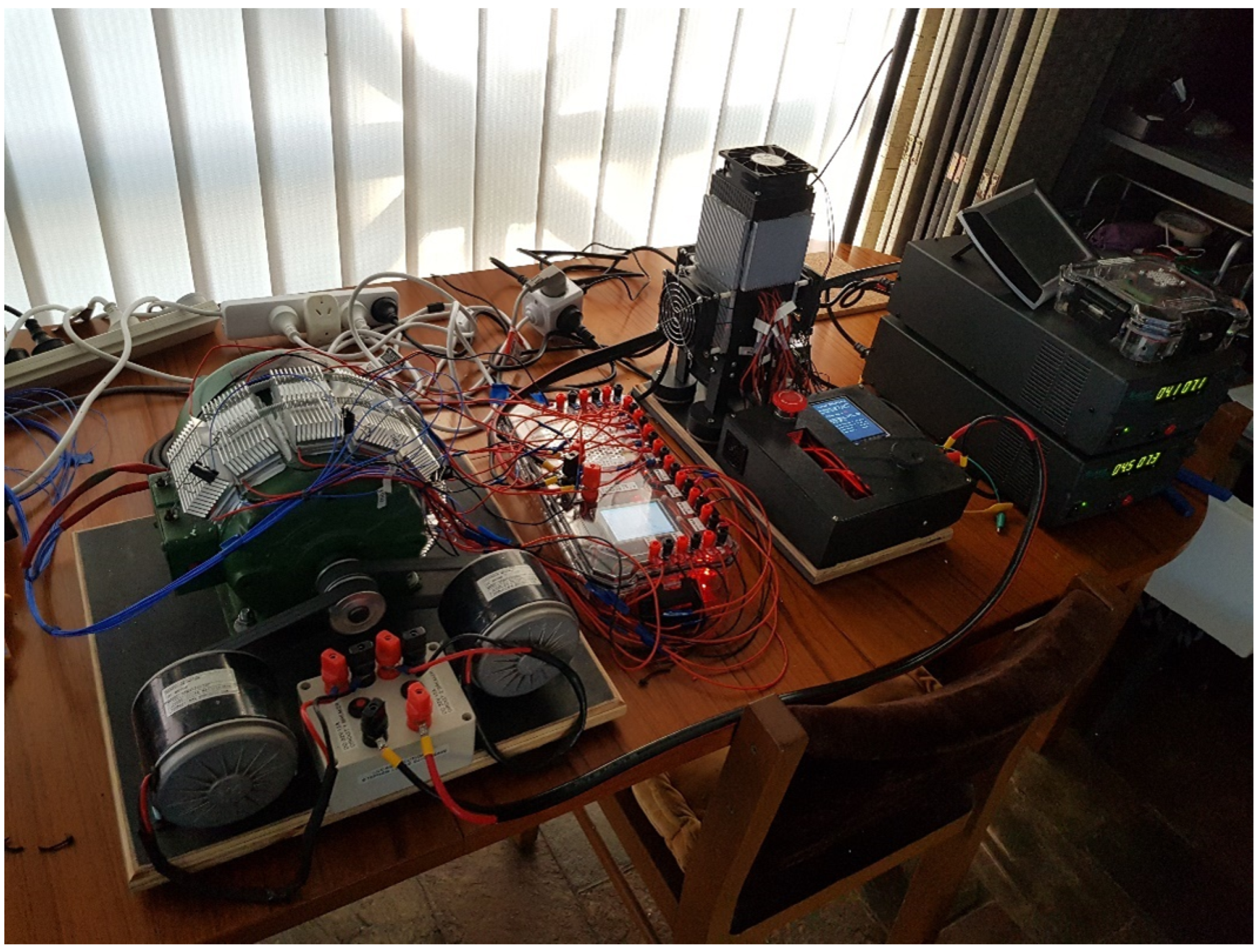
The TEC data sheets are based on the cold plate being held at 0 C. In application, the operation of the cold plate is likely to be subjected to climatic and industrial variations in temperature, so, six easily obtained TECs were tested to develop a better understanding of their operational performance. The test setup in Figure 4, also shown in Figure 9 in [22], was developed to allow the TECs to be tested and the performance characteristics to be compared.
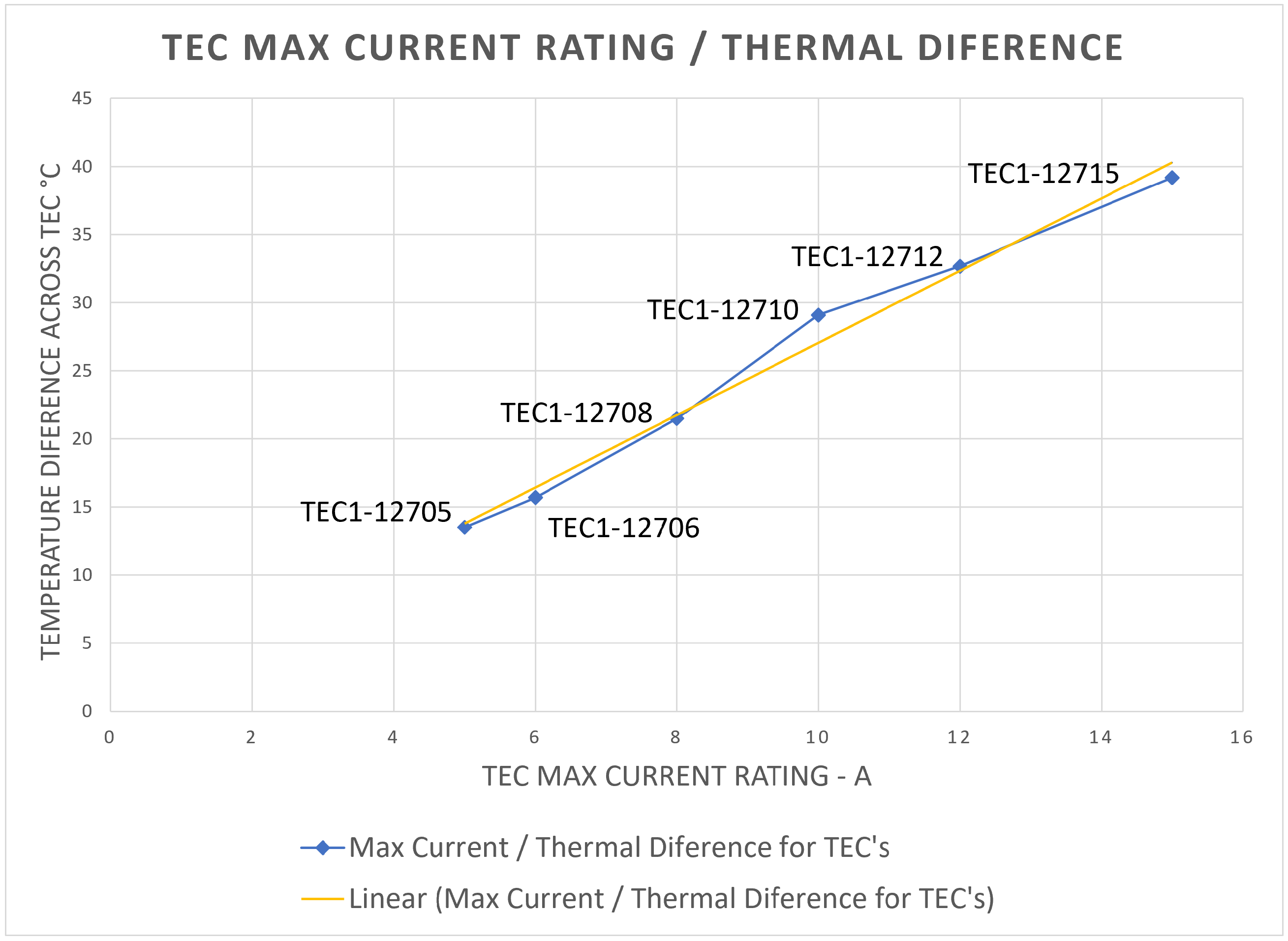
Each of the TECs was installed into the test rig in turn, and the current was increased in 0.5 A steps until its rating was reached. A plot of the TEC current rating against the temperature is shown in Figure 5. As can be seen, the temperature gains were linear in proportion to the maximum TEC current rating.
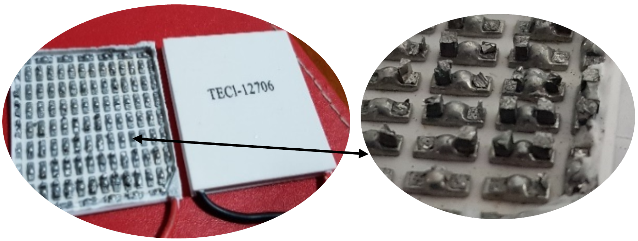
The thermoelectric cooler (Peltier Module) chosen for this project was the TEC1-12706 (Figure 3). This unit was the lowest cost unit (AUD 3.21 per module) readily available online with operational characteristics suitable for experimentation. It had a 60 W cooling capability at nominally 12 V and 6 A. Further information and specification data are readily available in [23,24].
3. Experimental Test on a Motor and the Results
Previous research [22] by the authors used TECs to heat a core sample from a section of a motor’s inner core encompassing the winding slot area. This paper explores the previously untried application of TECs to heat a single phase 3/4HP (559 W) induction test motor. Four systems were employed namely: resistors, heat sinks, heat pipes, and a water heat sink. This paper is not a comparison between the systems but rather an application of each system to gauge its effectiveness to heat up the motor from a stabilized room temperature.
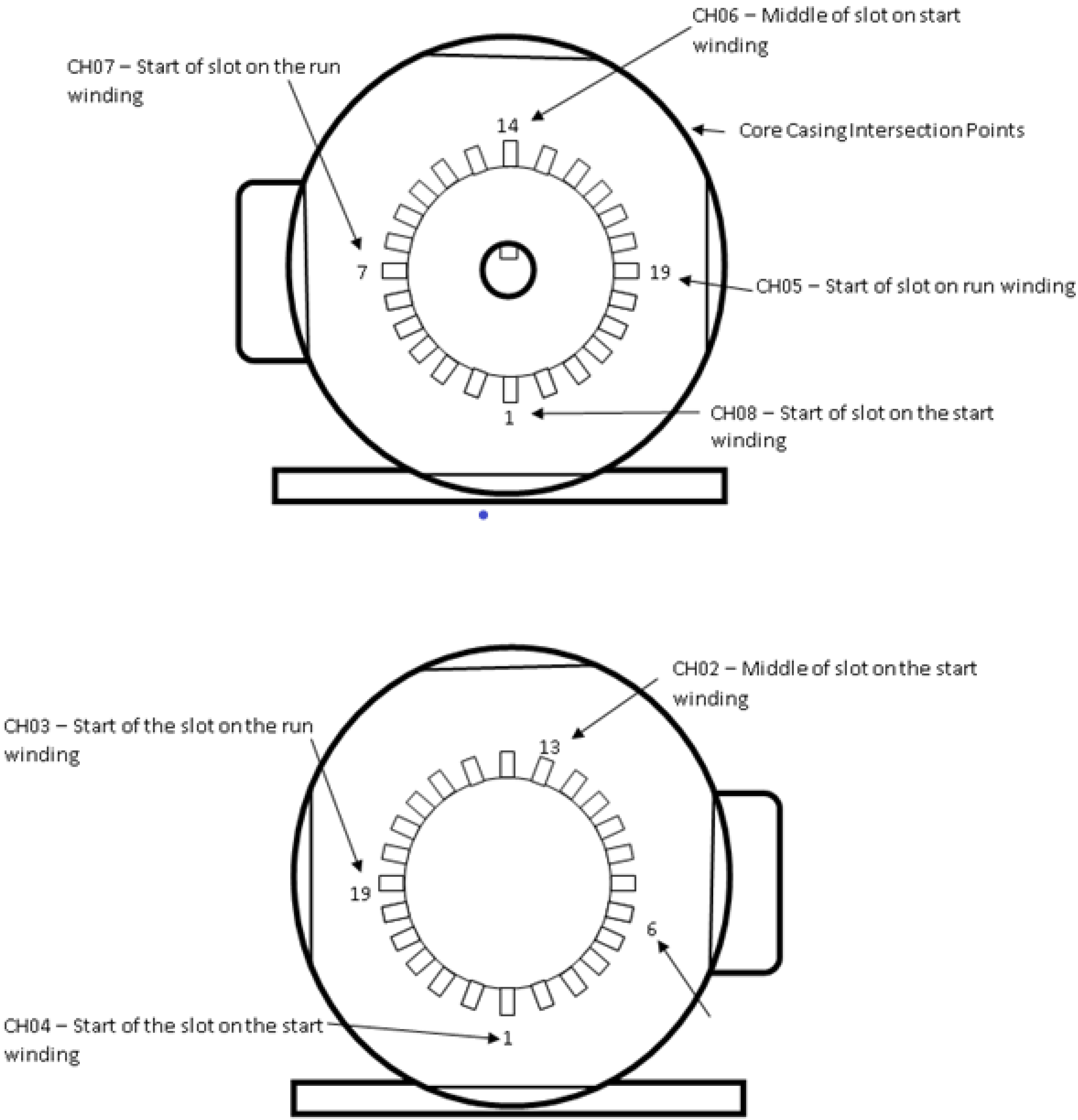
A motor with the same arrangement as a standard induction motor was selected as the test motor. The motor was dismantled and serviced (cleaned and varnished for mechanical stability, with new bearings installed), and eight new thermocouples were added to the windings as in Figure 6, to monitor and record the winding temperatures when under test. The slot area is a critical thermal area, and all data presented in this paper were taken from slot 13 (CH02, see Figure 6), as a thermocouple was inserted into the centre of the slot.
The test motor was switched off and allowed to stabilize at room temperature. There were four different configuration arrangements:
- Resistive heating;
- TECs with small heat sinks;
- TECs with heat pipe coolers;
- TECs with water circulation heat sinks.
With the motor at room temperature, the heating power supply was applied to each system. The polarity to the TECs was established so that the TEC pumped heat into the motor (the side against the motor became hot). The current supply to the configuration was adjusted in 0.5 A steps, with the input power to the resistor heaters and the TECs, and the resulting temperatures were recorded for each of the applied systems.
3.1. Resistive Heating
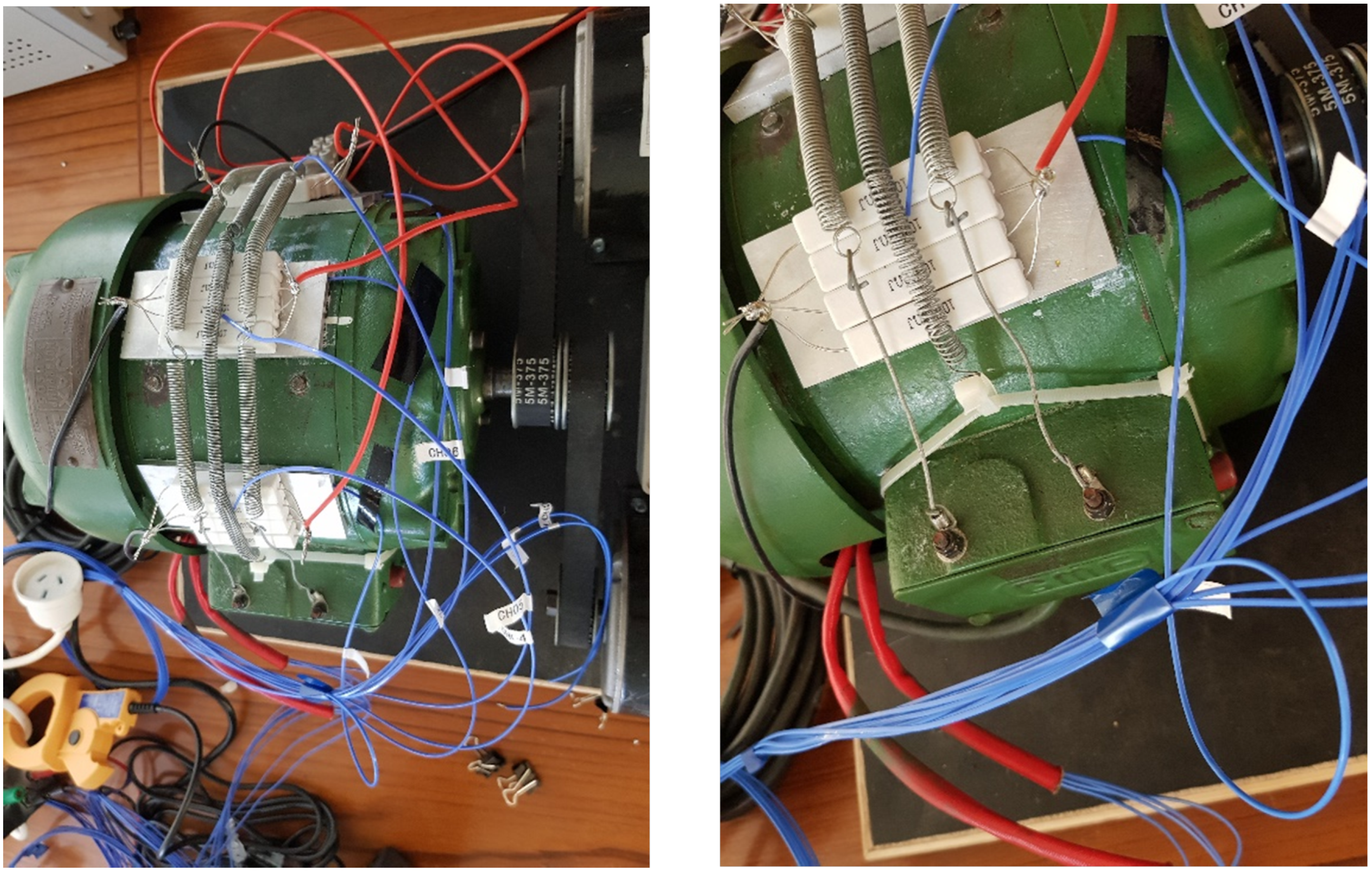
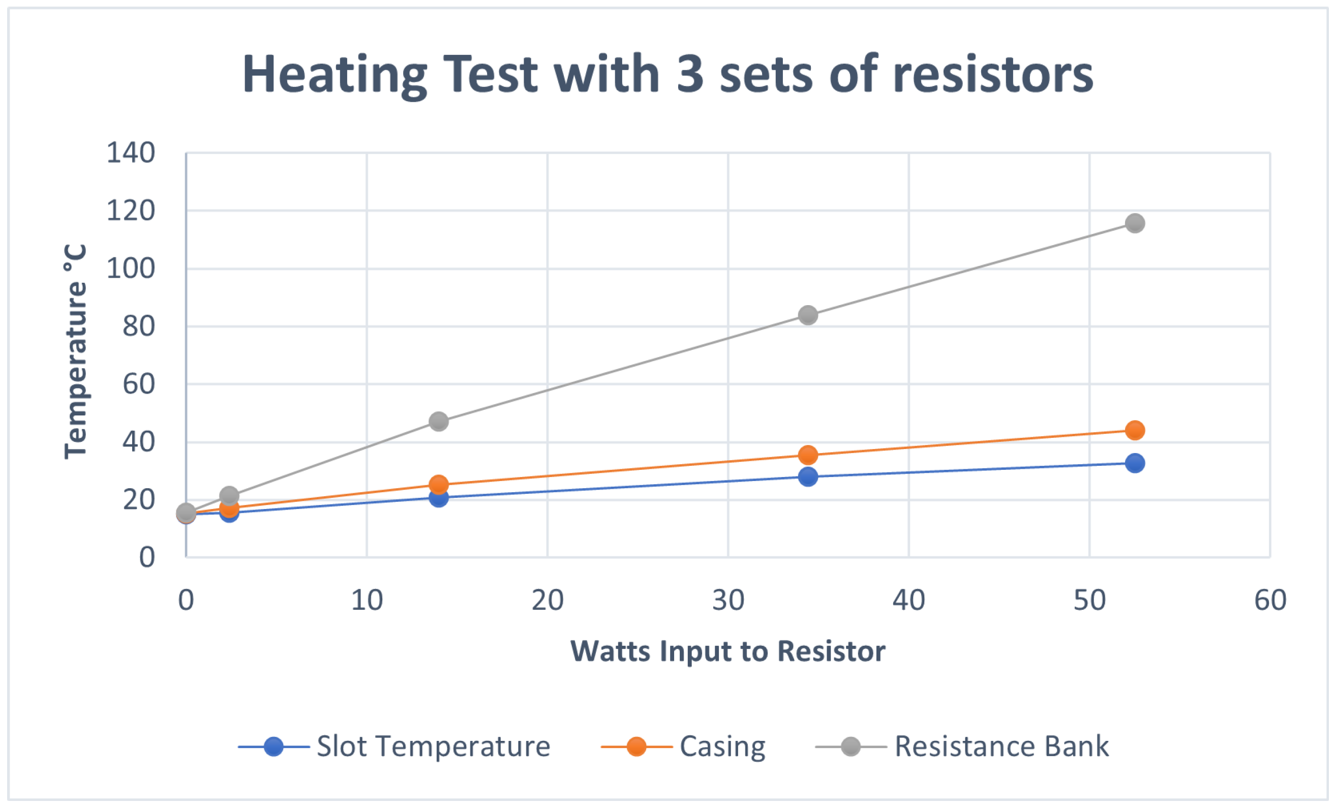
The resistive heater system is the most common heating method in motors today. The resistive heating system used in this paper comprised three resistor heating banks attached to the outer surface of the motor (see Figure 7). This arrangement heated the motor, the core, and the slot where the stator windings were inserted. Although applied in a different manner, as they are normally installed inside the motor under the windings, they did raise the winding temperatures. The slot, casing, and resistance bank temperatures at various total power inputs to the resistors were recorded and plotted in Figure 8. At a nominal 50 W input, the slot temperatures reached 32.1 C as shown in Figure 8, attaining thermal stability after 5 h.
3.2. TECs with Small Heat Sinks
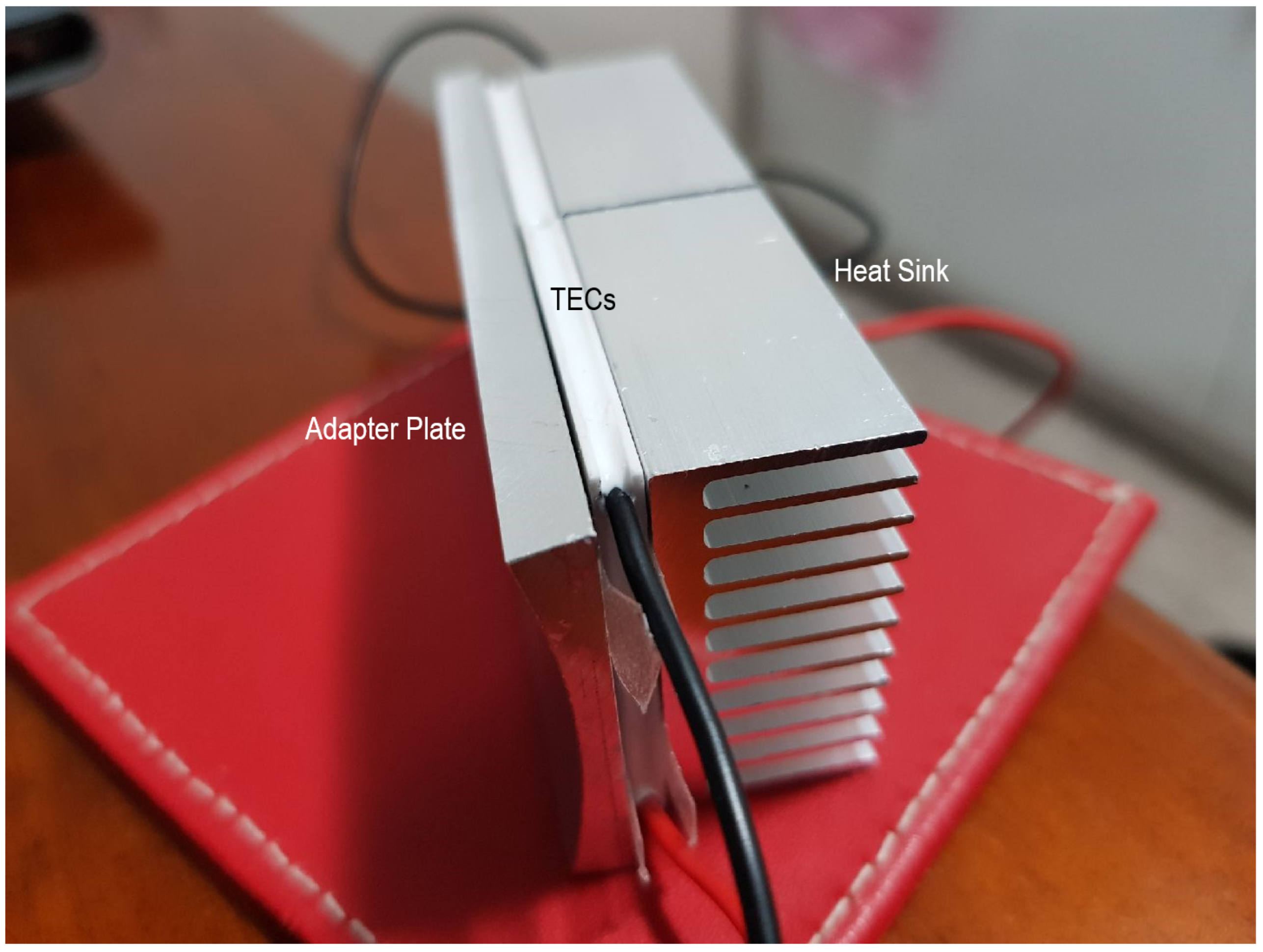
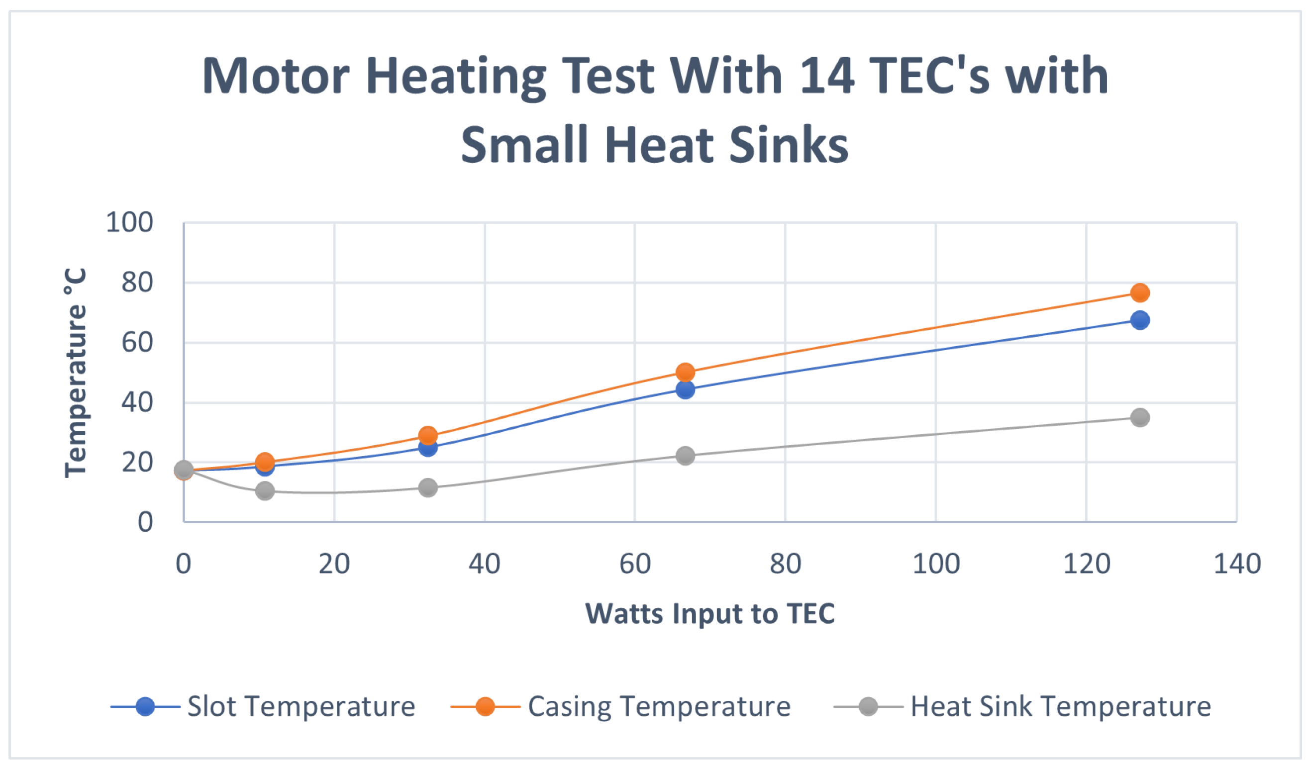
With this configuration, 14 TECs with small heat sinks were attached to the outer surface of the motor as shown in Figure 9. The TECs with small heat sinks had a small footprint, which allowed the largest application of the units to the test motor. This enabled a large coverage (14 TECs) of the casing, which minimized the losses from exposed surfaces. The mounting arrangement of the TECs was via a curved aluminium adapter plate (Figure 10), and the curve matched the diameter of the motor casing. Figure 11 shows a plot of the slot, casing, and heat sink temperatures at various total power inputs to the TECs. For a power less than 60 W, the temperature of the heat sink dropped below the atmospheric temperature due to the extraction of the heat from the environment and pumping it into the motor, coupled with the small area of the heat sinks. The temperature of the heat sink increased slightly when the input power was above 60 W due to the Joule effect. At the nominal 50 W input, the winding slot in the core reached 34.95 C, attaining thermal stability after 4.5 h (Figure 11).
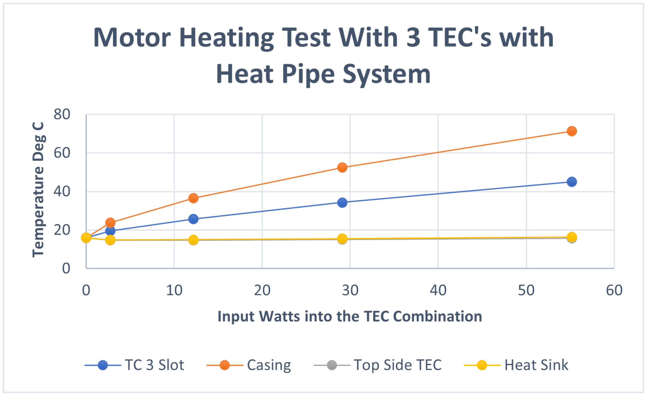
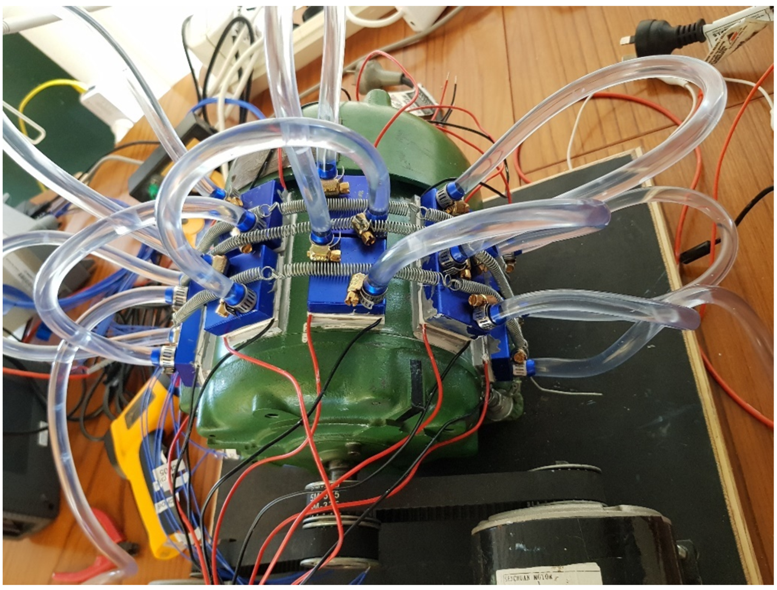
3.3. TECs with Heat Pipe Coolers
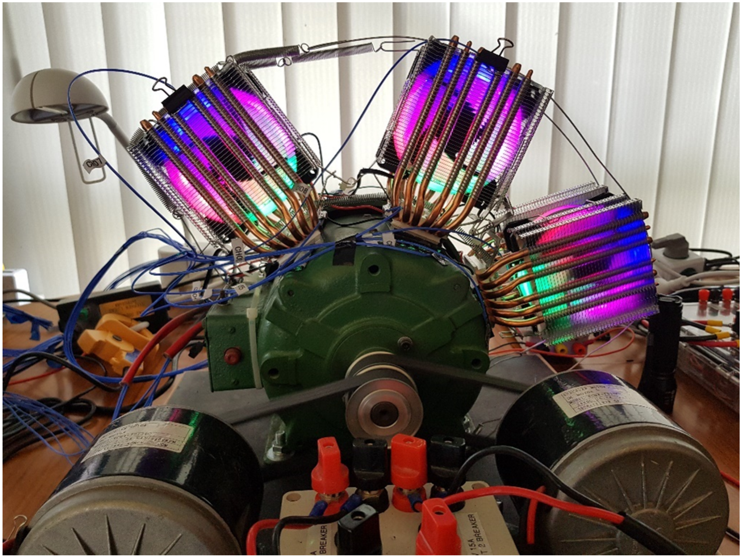
This configuration consisted of TECs with heat pipe coolers attached to the outer surface of the motor (see Figure 12). The system utilizing the heat pipe heat exchangers [25,26] took up room; hence, only three TECs were used in this configuration. The recorded slot, casing, TEC top side, and heat sink temperatures at various total power inputs to the TECs are shown in Figure 13. At the nominal 50 W input power to the inner core area, the motor slots reached 42.93 C, attaining thermal stability after 5 h (Figure 13).
The system, because of the greater area of the heat sinks, was more efficient.
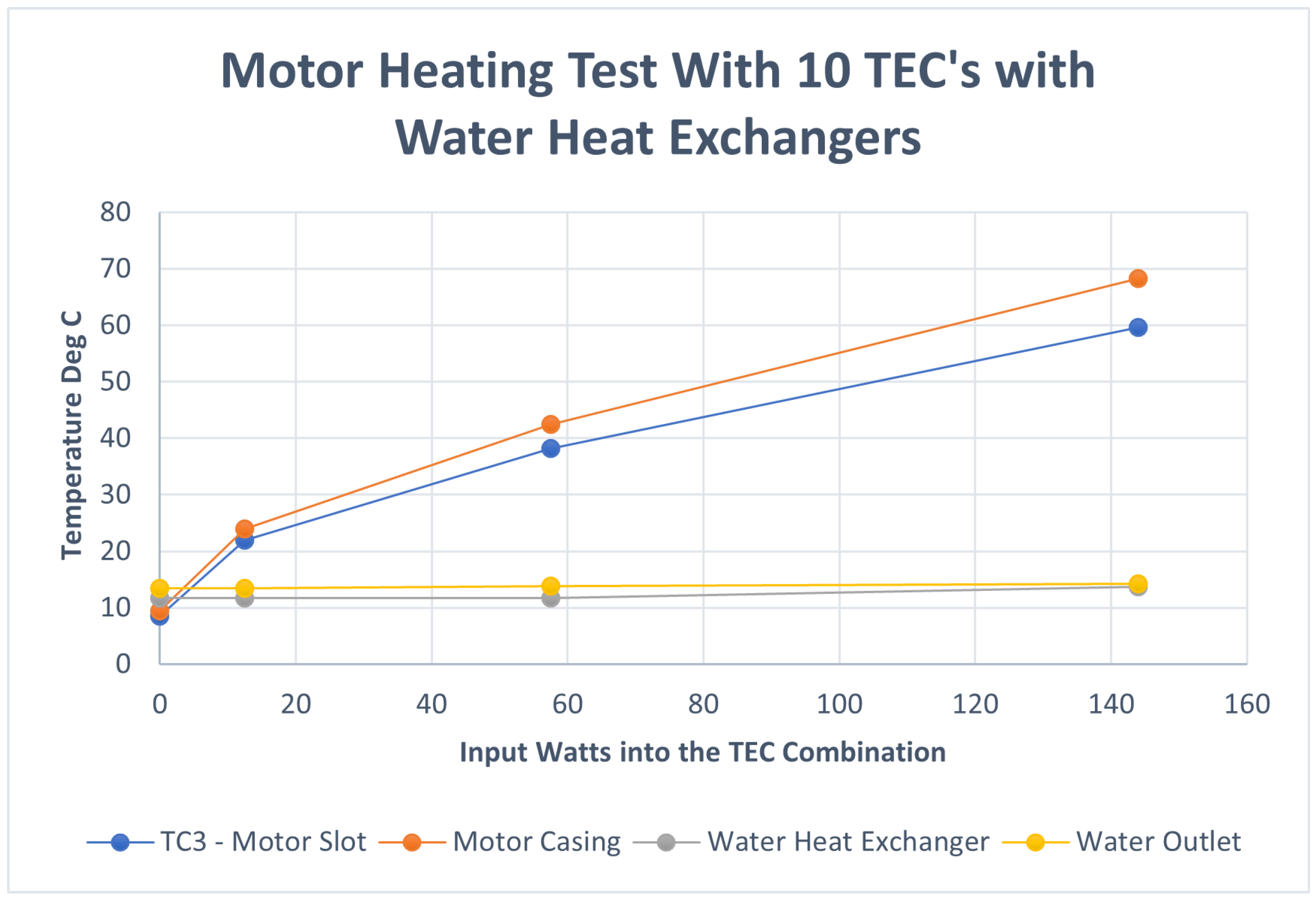
3.4. TECs with Water Circulation Heat Sinks
The configuration considered here comprised TECs with water circulation heat sinks attached to the outer surface of the motor (see Figure 14). The heating system consisted of 10 TECs with water heat sinks and water running at 12 C. This system worked similarly to the TECs with the small heat sinks. The recorded slot, casing, heat exchanger, and water outlet temperatures at various total power input to the TECs are plotted in Figure 15. With the water temperature at a low 12 C at the heat source, the TEC combination performance was slightly limited, but at the 50 W nominal input setting, it raised the inner core windings to 35.48 C, attaining thermal stability after 5 h (see Figure 15).
4. Discussion
The resistive heating system, the most common system employed by manufacturers because of its low cost and ease of installation, is normally mounted internally. In this position, it heats the internal air, limiting its ability to heat the entire volume of the machine. There is thermal loss via the external surfaces, and the internal volume conducts the heat to these surfaces. This thermal path causes a thermal lag between the internal and external temperatures and limits the resistive heating systems’ ability to stop internal condensation. The resistive system arrangement used in this study attached the resistive heating elements to the outside casing of a motor, and as this was the normal radiating surface, in this position, they could not be insulated, thus, the losses to the surroundings were high. The location had one major advantage; it was attached directly to the steel core, which conducted the heat quickly to the inner winding slot area. The results showed that at the nominal input power of 50 W, the winding temperature reached 32.14 C, only a few degrees cooler than the other systems despite its simplicity. The results also showed that this system could make a difference, especially to very small motors where there is not enough room to internally mount resistive heaters.
In the TEC and heat sink system, there was a combination of seven adapter plates and 14 TECs with heat sinks. This system was simple to install with the adapter plates. This enabled the largest coverage of the external surface, reducing the surface losses; however, the very small heat sinks limited the TEC’s ability to transfer or collect and pump the heat into the core. These worked well, and the slot temperature was easily able to be pushed up to 68 C. At the nominal input power of 50 W, the inner core reached 34.95 C. The main limitation was the very small size of the heat sinks. Larger units would have improved the TEC’s ability to draw heat from the heat sink; however, this inexpensive system worked well and proved the concept.
In the TEC and water circulation heat sink system, there were 10 TECs. This system was difficult to assemble and install, as water tubing with tube clamps was required to be fitted to each heat sink. In a water cooled system, there is a lot of extra equipment such as pumps, radiators and fans. This equipment significantly increased the required footprint for the installation and added considerably to the system costs and particularly the maintenance costs. The results were comparable with the heat sink system. The cold water holding the heat exchangers at 12 C limited the ability of the TECs to pump heat into the motor, but at the nominal input power of 50 W, the inner core reached 35.48 C.
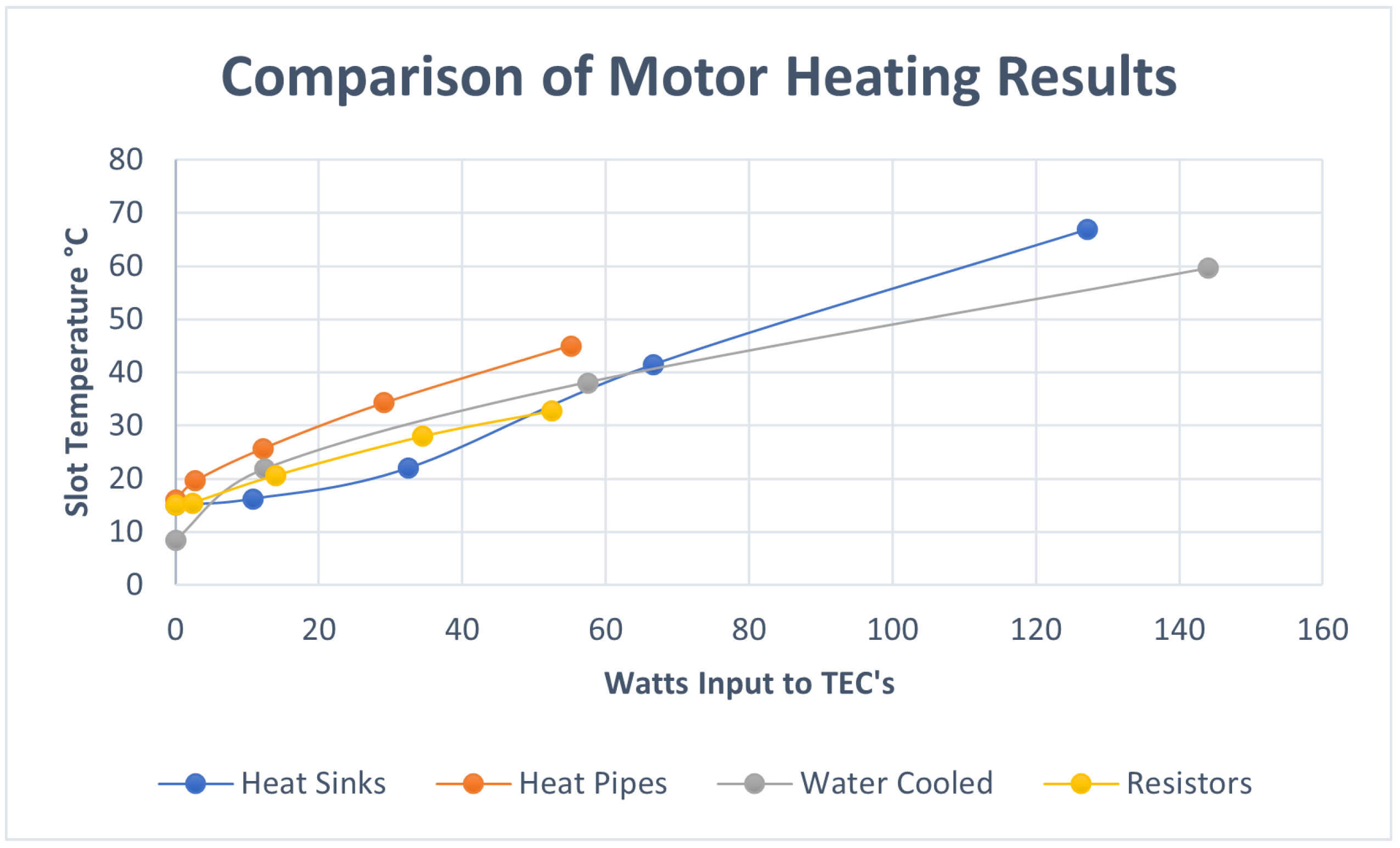
From Table 1, the three TECs connected to the fan cooled radiators via heat pipes resulted in the best result compared to the other heating systems. With a nominal input power of 50 W, the inner core reached 42.95 C. This was achieved with only a small area covered by three TECs. The advantage of this configuration was that it connected the TECs via the casing to the core, which efficiently conducted the heat to the inner core area, where the stator winding was located. This system also demonstrated the potential to locate the heat exchangers away from the motor. In confined conditions such as electric cars and portable compressor stations, this would enable the heat exchangers to be in a more appropriate area than the motor location. The disadvantage, however, is that the fan cooled radiators need to be located in an open area and are fairly large.
The three TEC heating systems employed in this paper are commonly found in thermal control applications. The mounting of these systems to the outer surface or flat surfaces is simple as the TECs are flat units. For round motors, a simple adapter plate can be used. For ribbed motors, a more complex adapter plate is required. These systems can be used post manufacture.
The TEC systems are inexpensive and have a major advantage over the existing heating systems in that they can pump heat directly into the volume of the motor, raising the temperature well beyond the dew point and eliminating the condensation issues. For new machines, the incorporation of TECs could be implemented during the design phase and could be placed between the core and casing.
5. Conclusions
This work has demonstrated that the application of TECs can effectively pump heat into the core of electrical motors and generators, raising the core temperatures. All three TEC heat pumping systems were effective, and the choice between the approaches would be application driven. The results of applying the TECs in these three cases showed that for all three arrangements, the application of 50 W of power to the TECs resulted in an increase in the slot temperature of a 500 W induction motor to more than 20 C above the ambient temperature.
TECs can pump heat in either direction, and previous studies have shown that TECs can pump heat out of a motor. A future study will examine the viability of dynamically managing a stable electrical motor core temperature in a varying ambient environment by utilizing controlled TECs to pump heat into and out of the core as required.
Author Contributions
Conceptualization, S.L., R.M. and J.C.; Investigation, S.L.; Project administration, R.M.; Resources, M.L. and J.C.; Supervision, R.M. and M.L.; Writing—original draft preparation, S.L. and R.M. Writing—review and editing, S.L., T.O., J.C., M.L. and R.M. All authors have read and agreed to the published version of the manuscript.
Funding
This research received no external funding.
Data Availability Statement
The data presented in this study are available on request from the corresponding author.
Conflicts of Interest
The authors declare no conflict of interest.
References
- Maughan, C.; Gibbs, E.; Giaquinto, E. Mechanical testing of high voltage stator insulation systems. IEEE Trans. Power Appar. Syst. 1946, PAS-89, 1946–1954. [Google Scholar] [CrossRef]
- Cowern, E. Keep Your Motor Dry in Damp Environments. 2001. Available online: https://www.ecmweb.com/content/article/20886991/keep-your-motor-dry-in-damp-environmrnts (accessed on 19 September 2012).
- Kim, C.; Lee, K. Numerical Investigation of the Air-Gap Flow Heating Phenomena in Large-Capacity Induction Motors. Int. J. Heat Mass Transf. 2017, 10, 7. [Google Scholar] [CrossRef]
- Jeftenic, I.; Stankovic, K.; Kartalovic, N.; Loncar, B. Life Expectancy Determination of Form-Wound Coil Isolation of High-Voltage Motor. In Proceedings of the 2016 IEEE International Power Modulator and High Voltage Conference (IPMHVC), San Francisco, CA, USA, 6–9 July 2016. [Google Scholar] [CrossRef]
- Nemirovskiy, A.; Kichigina, G.; Sergievskaya, I.; Udaratin, A.; Alyunov, A.; Gracheva, Y. Improving the Efficiency of Electroosmotic Drying of Electric Motors Insulation. E3s Web Conf. 2020, 178, 01061. [Google Scholar] [CrossRef]
- Khudonogov, A.M.; Khudonogov, I.A.; Dulskiy, E.Y.; Ivanov, P.Y.; Lobytsin, I.O.; Khamnaeva, A.A. Reliability Analysis of Power Equipment of Traction Rolling Stock Within the Eastern Region. IOP Conf. Ser. Mater. Sci. Eng. 2020, 760, 012018. [Google Scholar] [CrossRef]
- Zhang, P.; Du, Y.; Habetler, T.G.; Lu, B. A Nonintrusive Winding Heating Method for Induction Motor Using Soft Starter for Preventing Moisture Condensation. IEEE Trans. Ind. Appl. 2011, 48, 117–123. [Google Scholar] [CrossRef]
- Keithly, W.R.; Axe, S.P. A unique solution to improving motor winding life in medium-voltage motors. IEEE Trans. Ind. Appl. 1984, IA-20, 514–518. [Google Scholar] [CrossRef]
- Li, W.; Cotton, I.; Lowndes, R. Effects of Electrical Conductivity of Contamination on Tracking Formation in Aerospace Electrical Systems. In Lecture Notes in Electrical Engineering, Proceedings of the 21st International Symposium on High Voltage Engineering, Budapest, Hungary, 26–30 August 2019; Németh, B., Ed.; Springer: Cham, Switzerland, 2020; Volume 599, p. 599. [Google Scholar] [CrossRef]
- EASA. EASA Technical Manual. 2002. Available online: https://easa.com/resources/easa-technical-manual (accessed on 19 September 2012).
- Gallonia, E.; Parisia, P.; Marignettib, F.; Volpec, G. CFD Analyses of a Radial Fan for Electric Motor Cooling. Therm. Sci. Eng. Prog. 2018, 8, 470–476. [Google Scholar] [CrossRef]
- Giangrande, P.; Madonna, V.; Nuzzo, S.; Galea, M. Moving Toward a Reliability-Oriented Design Approach of Low-Voltage Electrical Machines by Including Insulation Thermal Aging Considerations. IEEE Trans. Transp. Electrif. 2020, 6, 16–27. [Google Scholar] [CrossRef]
- Pai, V.S. Preservation of large motors and generators from weather on offshore platforms. IEEE Trans. Ind. Appl. 1990, 26, 914–918. [Google Scholar] [CrossRef]
- Guastavino, F.; Torello, E.; Dardano, A.; Bono, S.; Pellegrini, M.; Vignati, L. A comparison of the short and long term behaviour of nanostructured enamels with the performances of conventi. In Proceedings of the Seventh International Conference on Machine Learning and Cybernetics, Kunming, China, 12–15 July 2008. [Google Scholar]
- Branch, F.E. Keeping Motor Windings Dry. 1991. Available online: https://www.usbr.gov/power/data/fist/fist3_4/vol3-4.pdf (accessed on 10 September 2022).
- Thomas, R. Preventing Condensation in 3-Phase AC Motors. 1996. Available online: https://www.ecmweb.com/content/article/20888577/preventing-condensation-in-3phase-ac-motors (accessed on 19 September 2012).
- Finley, W.; Wilson, C.; Burke, R. Storage of electric motors. In Conference Record of 1995. In Proceedings of the Annual Pulp and Paper Industry Technical Conference, Vancouver, BC, Canada, 6 August 1995; pp. 74–81. [Google Scholar] [CrossRef]
- Lysenko, D.A.; Konyukhov, V.Y.; Astashkov, N.P. Implementation of the control algorithm of the traction electric equipment. J. Phys. Conf. Ser. 2021, 2061, 012135. [Google Scholar] [CrossRef]
- Livotov, P.; Sekaran, A.P.C.; Mas’udah; Law, R.; Reay, D. Eco-Innovation in Process Engineering—Contradictions, Inventive Principles and Methods. Therm. Sci. Eng. Prog. 2019, 9, 14. [Google Scholar] [CrossRef] [Green Version]
- U.S. Department of Energy. Chapter 6 Innovating Clean Energy Technologies in Advanced Manufacturing Direct Thermal Energy Con 2015. p. p. 26. Available online: https://www.energy.gov/sites/default/files/2015/12/f27/QTR2015-6G-Direct-Thermal-Energy-Conversion-Materials-Devices-and-Systems.pdf (accessed on 19 September 2012).
- Sunawar, A.; Garniwa, I.; Hudaya, C. The characteristics of heat inside a parked car as energy source for thermoelectric generators. Int. J. Energy Environ. Eng. 2019, 10, 347–356. [Google Scholar] [CrossRef] [Green Version]
- Lucas, S.; Marian, R.; Lucas, M.; Ogunwa, T.; Chahl, J. Research in life extension of electrical motors by controlling the impact of the environment through employing Peltier effect. Energies 2022, 15, 7659. [Google Scholar] [CrossRef]
- Hebei, I.T. TEC1-12706 Thermoelectric Cooler. Shanghai Co Ltd. Available online: https://www.hebeiltd.com.cn (accessed on 20 November 2022).
- Espressomilkcooler. Specification of Thermoelectric Module TEC1-12706. 1997. Available online: https://espressomilkcooler.com/wp-content/uploads/2015/03/TEC1-12706-site-ready.pdf (accessed on 20 November 2022).
- Adera, S.; Antao, D.; Raj, R.; Wang, E.N. Design of Micropillar Wicks for Thin-Film Evaporation. Int. J. Heat Mass Transf. 2016, 101, 15. [Google Scholar] [CrossRef] [Green Version]
- Bai, C.; Qiu, Y.; Wei, M.; Tian, M. Converging-Shaped Small Channel for Condensation Heat Transfer Enhancement Under Varying-Gravity Conditions. Int. Commun. Heat Mass Transf. 2021, 123, 11. [Google Scholar] [CrossRef]
Figure 1.
The relationship between the air temperature, the dew point, and the humidity (adapted from [2]).
Figure 1.
The relationship between the air temperature, the dew point, and the humidity (adapted from [2]).

Figure 2.
Schematic diagram of a typical thermoelectric module (adapted from [21]).
Figure 2.
Schematic diagram of a typical thermoelectric module (adapted from [21]).

Figure 3.
The Peltier (cooling module) arrangement.

Figure 4.
The TEC test layout.

Figure 5.
The thermoelectric cooler (TEC) max current versus the temperature of the tested TECs.

Figure 6.
Schematic showing the placement of the thermocouples on the motor being tested. (Top): Front view. (Bottom): Back view.
Figure 6.
Schematic showing the placement of the thermocouples on the motor being tested. (Top): Front view. (Bottom): Back view.

Figure 7.
Resistive heating of the test motor.

Figure 8.
The graphed results of the heating with the resistors.

Figure 9.
The setup of the heating of the test motor with the TECs and small heat sinks.

Figure 10.
An adapter plate with the TEC and heat sink setup.

Figure 11.
The graphed results of the heating with the TECs and small heat sinks.

Figure 12.
The setup of the heating of the test motor with the TECs and heat pipe coolers.

Figure 13.
The graphed results of the heating with the TECs and heat pipe coolers.

Figure 14.
The setup of the heating of the test motor with the TECs and water cooled heat sinks.

Figure 15.
The graphed results of the heating with the TECs and water cooled heat sinks.

Figure 16.
Comparison of the heating setup results.


Table 1.
Comparison of the heating setups.
| Setup | Resistive Heating | Heat Sink | Heat Pipe | Water Cooled |
|---|---|---|---|---|
| Arrangement | Three heating elements | 14 TECs with heatsinks | Three TECs with heat pipes and radiators | 10 TECs with water heat exchangers |
| Arrangement Cost | AUD 15.00 | AUD 78.68 | AUD 144.78 | AUD 59.65 |
| Complexity | Simple | Slightly Difficult | Slightly more difficult | Difficult |
| Physical Size | Minimal | Small | Large but flexible | Large when including heat exchanger |
| Performance at 50 W | 32.14 C | 34.95 C | 42.93 C | 35.48 C |
| Issues | Limited effectiveness. | Adapter plates for mounting. Effectiveness limited by heat sink size. | Adapter plates for mounting. Large heat exchangers. Flexible mounting by utilisation of heat pipes. | Adapter plates for mounting. Extra maintenance. Larger install area. |
Disclaimer/Publisher’s Note: The statements, opinions and data contained in all publications are solely those of the individual author(s) and contributor(s) and not of MDPI and/or the editor(s). MDPI and/or the editor(s) disclaim responsibility for any injury to people or property resulting from any ideas, methods, instructions or products referred to in the content. |
© 2023 by the authors. Licensee MDPI, Basel, Switzerland. This article is an open access article distributed under the terms and conditions of the Creative Commons Attribution (CC BY) license (https://creativecommons.org/licenses/by/4.0/).
Share and Cite
MDPI and ACS Style
Lucas, S.; Marian, R.; Lucas, M.; Ogunwa, T.; Chahl, J. Employing the Peltier Effect to Control Motor Operating Temperatures. Energies 2023, 16, 2498. https://0-doi-org.brum.beds.ac.uk/10.3390/en16052498
AMA Style
Lucas S, Marian R, Lucas M, Ogunwa T, Chahl J. Employing the Peltier Effect to Control Motor Operating Temperatures. Energies. 2023; 16(5):2498. https://0-doi-org.brum.beds.ac.uk/10.3390/en16052498
Chicago/Turabian StyleLucas, Stephen, Romeo Marian, Michael Lucas, Titilayo Ogunwa, and Javaan Chahl. 2023. "Employing the Peltier Effect to Control Motor Operating Temperatures" Energies 16, no. 5: 2498. https://0-doi-org.brum.beds.ac.uk/10.3390/en16052498
Note that from the first issue of 2016, this journal uses article numbers instead of page numbers. See further details here.