Article

Establishment and Solution of Four Variable Water Hammer Mathematical Model for Conveying Pipe

1
College of Petroleum Engineering, Southwest Petroleum University, Chengdu 610500, China
2
CNPC Key Laboratory of Oil & Gas Storage and Transportation, Southwest Petroleum University, Chengdu 610500, China
3
CCDC Downhole Service Company, Chengdu 610500, China
*
Author to whom correspondence should be addressed.
Submission received: 7 January 2022 / Revised: 9 February 2022 / Accepted: 11 February 2022 / Published: 14 February 2022
(This article belongs to the Collection State of the Art Geo-Energy Technology in China)

Abstract

:
Transient flow in pipe is a much debated topic in the field of hydrodynamics. The water hammer effect caused by instantaneous valve closing is an important branch of transient flow. At present, the fluid density is regarded as a constant in the study of the water hammer effect in pipe. When there is gas in the pipe, the variation range of density is large, and the pressure-wave velocity should also change continuously along the pipe. This study considers the interaction between pipeline fluid motion and water hammer wave propagation based on the essence of water hammer, with the pressure, velocity, density and overflow area set as variables. A new set of water hammer calculation equations was deduced and solved numerically. The effects of different valve closing time, flow rate and gas content on pressure distribution and the water hammer effect were studied. It was found that with the increase in valve closing time, the maximum fluctuating pressure at the pipe end decreased, and the time of peak value also lagged behind. When the valve closing time increased from 5 s to 25 s, the difference in water hammer pressure was 0.72 MPa, and the difference in velocity fluctuation amplitude was 0.076 m/s. The findings confirm: the greater the flow, the greater the pressure change at the pipe end; the faster the speed change, the more obvious the water hammer effect. High-volume flows were greatly disturbed by instantaneous obstacles such as valve closing. With the increase of time, the pressure fluctuation gradually attenuated along the pipe length. The place with the greatest water hammer effect was near the valve. Under the coupling effect of time and tube length, the shorter the time and the shorter the tube length, the more obvious the pressure fluctuation. Findings also confirm: the larger the gas content, the smaller the fluctuation peak of pipe end pressure; the longer the water hammer cycle, the smaller the pressure-wave velocity. The actual pressure fluctuation value was obviously lower than that without gas, and the size of the pressure wave mainly depended on the gas content. When the gas content increased from 1% to 9%, the difference of water hammer pressure was 0.41 MPa.

1. Introduction

Since the mid nineteenth century, the unsteady flow of fluid has been a much discussed topic for scholars. In steady flow, the parameter at any point does not change with time; while in unsteady flow, the parameter at any point is a function of time and changes with it [1,2]. When boundary conditions at the end of a pipeline change, the steady flow in the pipeline will also change accordingly, manifested as a sudden change in the flow rate and pressure of the fluid, which causes momentum conversion. The occurrence time of this phenomenon is generally very short, so it is called transient flow, also known as water hammer or water hammer [3,4]. At present, the most representative work on water hammer is “Transient Flow” written by Professor Streeter, an American hydraulicsist [5]. This monograph systematically explains the types of water hammer process, the mechanism and derivation of water hammer, the applicable conditions of the model and the corresponding solution method, etc. Today, the method of characteristics (MOC), first proposed in the monograph, are widely used to characterize the water hammer process.
The classical transient flow models of pressurized pipe flow all use a reservoir-pipe-valve system as the research object and close the valve as the research condition [6,7]. The mathematical model includes the motion equation and the continuity equation. The pipeline element is selected as the control body. The momentum equation is established by the momentum change of the fluid entering and exiting the control body, and the continuity equation is established by the mass conservation of the fluid entering and exiting the control body. When the valve is closed, a short section of fluid at the valve stops flowing instantaneously, and the next section of fluid next to this section of fluid and in the upstream direction is blocked, decelerating to a standstill. By analogy, the fluid in the tube gradually stops moving along the upstream direction. Since the kinetic energy of the fluid is reduced and converted into pressure energy, the pressure in the tube gradually increases along the upstream direction. That is, a pressure wave propagates upstream at a wave velocity a [8,9]. Figure 1 shows the movement of the liquid in a horizontal pipeline after the valve is suddenly closed at the end of a pipeline, ignoring the friction and local loss.
In recent years, many scholars have performed research on the transient flow in fluid pipelines. Baba [11] considered the numerical calculation of the transient flow model of a hydrogen-natural gas mixture in pipelines with different types of valves. The influence of the valve function was analyzed, and the calculation results under different mass ratios and gas mixture flow parameters were given. Wahba [12] used one-dimensional and two-dimensional water hammer models to numerically study the attenuation of turbulence in pipelines. The one-dimensional model was solved by the characteristic line method, and the two-dimensional model was solved by the semidiscretization method and the fourth-order Runge—Kutta method. Kandil [13] used the characteristic line method to numerically solve the water hammer equation and studied pressure fluctuations by changing the elastic modulus of the pipeline and Poisson’s ratio. Hossam [14] first used the wave characteristic line method to numerically simulate the transient flow in a viscoelastic pipe, re-derived the Joukowsky equation of the elastic pipe, and derived the quadratic equation of energy conservation in the viscoelastic pipe. Khamoushi [15] proposed a one-dimensional model of transient flow in non-Newtonian fluids, using Zielke’s unsteady friction solution for power law fluids and cross fluids. The time increment updated the weight function of the Zielke model. Abdeldayem [16] studied and explored the performance of different unsteady friction models in terms of accuracy, efficiency, and reliability to determine the most suitable model for engineering practice. Through comparison, it was found that Vítkovský’s unsteady friction model is the most suitable. Taking the reservoir-pipe-valve system as an example, the effectiveness of the method was verified by experimental data. Lashkarbolok [17] used radial-basis functions and least-squares optimization technology to solve the numerical solution of one-dimensional equations governing transient pipe flow. The method can deal with geometrically nonuniform pipes by employing an arbitrary distribution of scattering nodes in the space domain. Aliabadi [18] studied fluid-structure interaction (FSI) during water hammer in a viscoelastic (VE) pipe in the frequency domain. The main aim was to investigate pressure and stress waves using the transfer matrix method (TMM) in a typical reservoir-VE pipe-valve (RPV) system. Both major coupling mechanisms, namely Poisson and junction, are taken into account. Firouzi [19] proposed a time-varying reliability method to predict the failure risk of pipeline strength reduction due to the combination of water hammer pressure and corrosion and proposed the coupling model of pitting corrosion and water hammer pressure. It was found that with an increase in the average incidence of water hammer, the risk of pipeline failure increases, and the sudden closure of pipeline valves will have a destructive impact on the safety of a pipe network. Henclik [20] proposed an original concept of applying a shock response spectrum (SRS) method to water hammer events. The method is shortly presented, its numerical approach developed, and its application to water hammer loads described. SRS computations and analysis of water hammer experimental results measured at a laboratory pipeline are performed and concluded. Chen [21] constructed a fluid-solid coupling 4 equation model applied to high-temperature and high-pressure oil and gas based on the fluid-solid coupling theory and selected the best coupling method and combined the characteristic line method to obtain the pressure-wave velocity. Zhu [22,23] conducted a transient flow experiment using a sudden valve closing of a gas-liquid two-phase pressurized pipe flow and used the experiment to verify that the pressure-wave velocity of a pressurized pipe flow transient flow model was corrected by the gas content rate. At the same time, considering the nonconstant friction and the viscoelasticity of the pipe, the influence on gas flow and pressure-wave dissipation was studied, and the relevant parameters were checked. Fu [24,25] used the split-phase flow model to simulate the liquid column separation caused by transient flow in the pressure pipe flow and also considered the influence of the pipe stress wave on the pressure wave. Due to the existence of nonconservative terms in the model and to ensure the convergence of the results, this model needed to be solved separately while relaxation parameters were introduced. Han [26] examined bridging the water hammer in long-distance pipelines. He based his study on classic water hammer theory, considering the growth and reduction of cavities, the air content in the pipeline, and the water hammer after the instantaneous change in the pressure in the corrugated tube, among other factors. The process was described in semianalytical mathematics, and the influence of the growth and reduction time of cavities, the size of the gas content, and the relative elevation of the highest point of the pipeline to the horizontal section on bridging the water hammer pressure was analyzed.
After investigation, it was found that a large number of domestic and foreign literatures regard the fluid density in the conveying pipe as a constant. When the fluid in the tube is all liquid, the error caused by the fluid density as a constant is within the engineering allowable range. However, when there is gas (natural gas, etc.) in the tube, the gas has different degrees of compressibility and the density varies widely. Treating it as a constant violates the actual process of fluid flow in the tube. The density is closely related to the pressure-wave speed, which should also be constantly changing along the pipeline.
Furthermore, when calculating water hammer pressure, earlier researchers did not consider the change and inconsistency of the research object at the beginning and end of the period due to fluid inflow and outflow in the dt period. Based on the essence of water hammer, the interaction between pipeline fluid motion and water hammer wave propagation is considered in this paper, and the pressure, velocity, density and overflow area are set as variables. A new set of water hammer calculation equations is deduced and solved numerically. The effects of different valve closing time, flow rate and gas content on pressure distribution and water hammer effect are studied. Such calculations of the propagation process of the water hammer wave are more reasonable and reliable.

2. Mathematical Model

2.1. Fluid Motion Equation

Taking the water body in the flow section of length x as the research object, this paper tracks it to study the water body in the flow section. The analysis diagram of the interaction between the pipe water movement and the water hammer wave propagation is shown in Figure 2. The initial length of the stream segment is set to x. The liquid in the flow section between section 1-1 and section 2-2 at the initial time is taken as the research object. Taking into account the original flow of the liquid, after the dt period, the flow segment 1-2 moves to a new position 1′-2′, and the crest of the water hammer wave also propagates to the position of section 1′-1′.
As shown in Figure 2, after the dt period, section 1-1 of the studied control body moves to the position of section 1′-1. The movement distance is ds. The water hammer wave moves from section 2-2 to Section 1′-1′ at wave speed c. The movement distance is y, and section 2-2 moves to Section 2′-2′.
At the beginning of dt, the momentum of the liquid in the 1-2 flow section is:
ρ + ρ s x 2 A + A s x 2 v + v s x 2 x = ρ A v x + 1 2 ρ A v s x 2 + 1 4 ρ A s v s + A ρ s v s + v ρ s A s x 3 + 1 8 ρ s A s v s x 4 ρ A v x + 1 2 ρ A v s x 2
At the end of time dt, the average density of the fluid in the 1′-2′ flow section is:
ρ ˜ = 1 2 ρ + ρ s d s + t ρ + ρ s d s d t + ρ + ρ s x + d l + t ρ + ρ s x + d l d t    ρ + ρ s d s + ρ t d t + 1 2 ρ s x
In the same way, at the end of time dt, the average area of the fluid in the 1′-2′ flow section is:
A ˜ A + A s d s + A t d t + 1 2 A s x
The average velocity of the fluid in the 1′-2′ stream section is:
v ˜ v + v s d s + v t d t + 1 2 v s x
Therefore, at the end of time dt, the fluid momentum in the 1′-2′ flow section is:
m o = ρ + ρ s d s + ρ t d t + 1 2 ρ s x A + A s d s + A t d t + 1 2 A s x v + v s d s + v t d t + 1 2 v s x y + d l = ρ A v x + ρ A v s x d s + ρ A v t x d t + 1 2 ρ A v s x 2 + ρ A v x v s d t
At the time of dt, the increase of momentum in the studied control body is:
m o = ρ A v x + ρ A v s x d s + ρ A v t x d t + 1 2 ρ A v s x 2 + ρ A v x v s d t ρ A v x + 1 2 ρ A v s x 2 = ρ A v s x d s + ρ A v t x d t + 1 2 ρ A v s x 2
The external force acting on the control body includes the hydrodynamic pressure of the cross-section at both ends, the hydrodynamic pressure of the side, gravity and the frictional resistance of the pipe wall. Because the distance of the control body movement in the dt period is very small, when analyzing the combined external force it receives, the analysis of the 1-2 flow section is equivalent to the 1′-2′ analysis. Therefore, at the time of dt, the impulse of the external force received by the control body is:
ρ A v s x d s + ρ A v t x d t + ρ A v x v s d t = p A s x + p A s x + ρ g A x sin θ τ 0 χ x d t
After sorting, the formula can be obtained:
1 ρ d ρ d p + 1 A d A d p d p d t + 1 v d v d t + v s + 1 ρ v p s g v sin θ + τ 0 χ ρ A v = 0
Through the simultaneous establishment of a one-dimensional unsteady continuity equation:
1 v v t + v s + 1 ρ v p s g v sin θ + τ 0 χ ρ A v = 0
Because of z s = sin θ , substitute the above formula to obtain:
1 g v t + v g v s + 1 γ p s + z s + τ 0 χ γ A = 0
Equation (10) is the water hammer motion equation.

2.2. Fluid Continuity Equation

The derivation of a water hammer continuity equation uses the law of mass conservation and takes the fluid in the flow section with length x as the research object, as shown in Figure 2. Both ends of the pipe section are section 1-1 and section 2-2, respectively.
The difference in the quality of the liquid flowing into and out of the control body during the dt period is:
1 g v t + v g v s + 1 γ p s + z s + τ 0 χ γ A = 0
At the beginning of the dt period, the fluid quality in flow section 1-2 is:
ρ + ρ s x 2 A + A s x 2 x ρ A x + 1 2 ρ A s x 2
At the end of the dt period, the fluid quality in flow section 1-2 is:
ρ + ρ s x 2 + ρ t d t A + A s x 2 + A t d t x ρ A x + ρ A s x 2 2 + ρ A t x d t
Therefore, the fluid mass increase in flow segment 1-2 during the dt period is:
ρ A x + ρ A s x 2 2 + ρ A t x d t ρ A x + ρ A s x 2 2 = ρ A t x d t
According to the law of conservation of mass, during the dt period, the difference between the mass of fluid flowing into and out of the control body should be equal to the increase in the mass of the fluid in the control body during the same period, that is:
ρ A t + ρ A v s = 0
Equation (15) is the water hammer continuity equation derived in this paper. Therefore, the water hammer calculation equations can be obtained as:
ρ A t + ρ A v s = 0 1 g v t + v g v s + 1 γ p s + z s + τ 0 χ γ A = 0

2.3. Complete Equations of Water Hammer

Generally in engineering, it is customary to use the piezometer head H to reflect the pressure p. Therefore, substituting p = ρ g H z into the equation of motion, we can get:
d p d t = p t + v p s = ρ g H z t + v ρ g H z s = ρ g d H z d t + g H z d ρ d t
where, z t = 0 , z s = sin θ , θ is the included angle between the pipe axis and the horizontal direction.
The above formula considers the variation of liquid density ρ with time t and distance s during water hammer, which is different from the traditional water hammer equations.
Since:
p s = ρ g H z s = γ H s γ z s + g H z ρ s
Then substitute γ = ρ g , τ 0 = 1 8 f ρ v 2 and χ 0 = π D = 2 π A into the equation of motion to obtain:
v t + v v s + g H s + H z g ρ ρ s + f v v 4 π A = 0
Since the fluid elasticity equation is:
1 ρ d ρ d p = 1 K
The elastic equation of the pipe is:
1 A d A d p = D E e
The simultaneous hydroelasticity Equations (20) and (19) can be obtained:
ρ t + v ρ s ρ K ρ g H z H t + v H s + v sin θ = 0
The simultaneous elastic equation of pipe (21) and Equation (19) can be obtained:
A t + v A s 2 A K E e A π K ρ g H z H t + v H s + v sin θ = 0
After sorting, the formula can be obtained:
H t + v H s + v sin θ + 1 ρ g H z K 2 E e A π + 1 K v s = 0
Thus, the water hammer closure equations are:
v t + v v s + g H s + H z g ρ ρ s + f v v 4 π A = 0 H t + v H s + v sin θ + 1 ρ g H z K 2 E e A π + 1 K v s = 0 ρ t + v ρ s ρ K ρ g H z H t + v H s + v sin θ = 0 A t + v A s 2 A K E e A π K ρ g H z H t + v H s + v sin θ = 0

3. Model Solving and Boundary Conditions

3.1. Difference Equation

In the calculation of water hammer equations, the more common methods are the characteristic line method and the direct difference method based on the finite difference method [27,28]. Because their deformation form cannot be transformed into characteristic equations, the characteristic line method cannot be used for calculation of the Gestalt equations proposed in this paper. Instead, the direct difference method is selected for calculation.
Compatibility, convergence and stability must be considered in difference calculations [28,29,30]. Change the differential equation into a difference equation. If the computational grid is reduced, the difference equation tends to be consistent with the differential equation. For example, the solution of the difference equation converges to the solution of the differential equation, which is convergence. If the rounding error and initial error in the calculation are always controlled within a limited range, and the calculated value is close to the true solution, then this scheme is stable. For the diffusion difference scheme adopted in this paper, the stability condition is the Courant condition. Since the water hammer equation is a hyperbolic equation, its stability condition should still meet the following requirements even though the concept of water hammer wave velocity is not introduced:
Δ s Δ t v   OR   Δ s Δ t v ± 1 ρ 1 K + D E e max
In order to solve this model, the basic equation needs to be discretized and the differential equation needs to be transformed into a differential algebraic equation. Here, the diffusion difference scheme is used to solve the equation. Figure 3 shows the L-t plane of characteristic grid of the four variable water hammer model. Use X to represent the objective function head H, velocity V and density ρ and area A. Then the partial differential of X to time and position can be expressed as:
X t = X i k ξ X i k 1 + 1 ξ 2 X i + 1 k 1 + X i 1 k 1 Δ t
X z = X i + 1 k 1 X i 1 k 1 2 Δ z
By introducing Equations (27) and (28) into the water hammer closure calculation model, the following difference equations can be obtained:
v i k ξ v i   k 1 + 1 ξ 2 v i + 1   k 1 + v i 1   k 1 Δ t + v i   k 1 v i + 1   k 1 v i 1   k 1 2 Δ z + g H i + 1   k 1 H i 1   k 1 2 Δ z + H i   k 1 g ρ i   k 1 ρ i + 1   k 1 ρ i 1   k 1 2 Δ z + f v i   k 1 v i   k 1 2 D = 0
H i k ξ H i   k 1 + 1 ξ 2 H i + 1   k 1 + H i 1   k 1 Δ t + v i   k 1 H i + 1   k 1 H i 1   k 1 2 Δ z + v i   k 1 sin θ + 1 ρ g H z K 2 E e A π + 1 K v i + 1   k 1 v i 1   k 1 2 Δ z = 0
ρ i k ξ ρ i   k 1 + 1 ξ 2 ρ i + 1   k 1 + ρ i 1   k 1 Δ t + v i   k 1 ρ i + 1   k 1 ρ i 1   k 1 2 Δ z ρ i   k 1 K ρ i   k 1 g H i   k 1 z i H i k ξ H i   k 1 + 1 ξ 2 H i + 1   k 1 + H i 1   k 1 Δ t + v i   k 1 H i + 1   k 1 H i 1   k 1 2 Δ z + sin θ = 0
A i k ξ A i   k 1 + 1 ξ 2 A i + 1   k 1 + A i 1   k 1 Δ t + v i   k 1 A i + 1   k 1 A i 1   k 1 2 Δ z 2 K A i   k 1 ρ i   k 1 E e A i   k 1 π ρ i k ξ ρ i   k 1 + 1 ξ 2 ρ i + 1   k 1 + ρ i 1   k 1 Δ t + v i   k 1 ρ i + 1   k 1 ρ i 1   k 1 2 Δ z = 0
Make the following assumptions:
X H 1 = ξ H i k 1 + 1 ξ 2 H i + 1 k 1 + H i 1 k 1 ,                         X H 2 = H i + 1 k 1 H i 1 k 1 Δ t Δ z X v 1 = ξ v i k 1 + 1 ξ 2 v i + 1 k 1 + v i 1 k 1 ,                                   X v 2 = v i + 1 k 1 v i 1 k 1 Δ t Δ z X ρ 1 = ξ ρ i k 1 + 1 ξ 2 ρ i + 1 k 1 + ρ i 1 k 1 ,                               X ρ 2 = ρ i + 1 k 1 ρ i 1 k 1 Δ t Δ z X A 1 = ξ A i k 1 + 1 ξ 2 A i + 1 k 1 + A i 1 k 1 ,                     X A 2 = A i + 1 k 1 A i 1 k 1 Δ t Δ z
After sorting, the expressions of the four unknowns are as follows:
H i k = X H 1 v i k 1 X H 2 2 + Δ t sin θ X v 2 1 ρ i k 1 g H i k 1 z i K 4 E e A i k 1 π + 1 K v i k = X v 1 v i k 1 2 X v 2 g 2 X H 2 H i k 1 z i g 2 ρ i k 1 X ρ 2 f Δ t 2 D v i k 1 v i k 1 = 0 ρ i k = X ρ 1 v i k 1 2 X ρ 2 + ρ i k 1 K ρ i k 1 g H i k 1 z i H i k X H 1 + v i k 1 X H 2 2 + Δ t sin θ A i k = X A 1 v i k 1 2 X A 2 + 2 A i k 1 K ρ i k 1 E e A i k 1 π ρ i k X ρ 1 + v i k 1 2 X ρ 2
The fluid in the oil pipeline is not all liquid in the field. What happens when there is a small amount of gas in the oil pipeline? Assuming that there are only gas-liquid two phases in the pipe, the density of the gas-liquid mixture is [31]:
ρ m = ρ g C g + ρ l 1 C g
where, Cg is the gas content.
Since the density in this paper is considered a variable, according to the difference principle, we can get:
ρ m i k = ρ g i k C g i k + ρ l i k 1 C g i k
ρ m i k 1 = ρ g i k 1 C g i k 1 + ρ l i k 1 1 C g i k 1
ρ m i + 1 k 1 = ρ g i + 1 k 1 C g i + 1 k 1 + ρ l i + 1 k 1 1 C g i + 1 k 1
ρ m i 1 k 1 = ρ g i 1 k 1 C g i 1 k 1 + ρ l i 1 k 1 1 C g i 1 k 1
Accordingly, the flow rate also becomes the mixing flow rate, and its expression is:
v m = Q g + Q l A
Then according to the difference principle, we can get:
v m i k = Q g i k + Q l i k A i k
v m i   k 1 = Q g i   k 1 + Q l i   k 1 A i   k 1
v m i + 1   k 1 = Q g i + 1   k 1 + Q l i + 1   k 1 A i + 1   k 1
v m i 1   k 1 = Q g i 1   k 1 + Q l i 1   k 1 A i 1   k 1
Thus, formulas (29)–(32) are deformed as:
v m i k ξ v m i   k 1 + 1 ξ 2 v m i + 1   k 1 + v m i 1   k 1 Δ t + v m i   k 1 v m i + 1   k 1 v m i 1   k 1 2 Δ z + g H i + 1   k 1 H i 1   k 1 2 Δ z + H i   k 1 g ρ m i   k 1 ρ m i + 1   k 1 ρ m i 1   k 1 2 Δ z + f v m i   k 1 v m i   k 1 2 D = 0
H i k ξ H i   k 1 + 1 ξ 2 H i + 1   k 1 + H i 1   k 1 Δ t + v m i   k 1 H i + 1   k 1 H i 1   k 1 2 Δ z + v m i   k 1 sin θ + 1 ρ m i   k 1 g H i   k 1 z K 2 E e A i   k 1 π + 1 K v m i + 1   k 1 v m i 1   k 1 2 Δ z = 0
ρ m i k ξ ρ m i   k 1 + 1 ξ 2 ρ m i + 1   k 1 + ρ m i 1   k 1 Δ t + v i   k 1 ρ m i + 1   k 1 ρ m i 1   k 1 2 Δ z ρ m i   k 1 K ρ i   k 1 g H i   k 1 z i H i k ξ H i   k 1 + 1 ξ 2 H i + 1   k 1 + H i 1   k 1 Δ t + v i   k 1 H i + 1   k 1 H i 1   k 1 2 Δ z + sin θ = 0
A i k ξ A i   k 1 + 1 ξ 2 A i + 1   k 1 + A i 1   k 1 Δ t + v i   k 1 A i + 1   k 1 A i 1   k 1 2 Δ z 2 K A i   k 1 ρ i   k 1 E e A i   k 1 π ρ m i k ξ ρ m i   k 1 + 1 ξ 2 ρ m i + 1   k 1 + ρ m i 1   k 1 Δ t + v i   k 1 ρ m i + 1   k 1 ρ m i 1   k 1 2 Δ z = 0
The corresponding assumptions will also be changed accordingly:
X v 1 m = ξ v m i   k 1 + 1 ξ 2 v m i + 1   k 1 + v m i 1   k 1 , X v 2 m = v m i + 1   k 1 v m i 1   k 1 Δ t Δ z X ρ 1 m = ξ ρ m i   k 1 + 1 ξ 2 ρ m i + 1   k 1 + ρ m i 1   k 1 , X ρ 2 m = ρ m i + 1   k 1 ρ m i 1   k 1 Δ t Δ z
After sorting, the expressions of four unknowns considering gas-liquid two-phase are obtained as follows:
H i k = X H 1 v m i k 1 X H 2 2 + Δ t sin θ X v 2 m 1 ρ m i k 1 g H i k 1 z i K 4 E e A i k 1 π + 1 K v m i k = X v 1 m v m i k 1 2 X v 2 m g 2 X H 2 H i k 1 z i g 2 ρ m i k 1 X ρ 2 m f Δ t 2 D v m i k 1 v m i k 1 = 0 ρ m i k = X ρ 1 m v m i k 1 2 X ρ 2 m + ρ m i k 1 K ρ m i k 1 g H i k 1 z i H i k X H 1 + v m i k 1 X H 2 2 + Δ t sin θ A i k = X A 1 v m i k 1 2 X A 2 + 2 A i k 1 K ρ m i k 1 E e A i k 1 π ρ m i k X ρ 1 m + v m i k 1 2 X ρ 2 m

3.2. Boundary Conditions

The boundary point is different from the inner node. It has an equation with boundary conditions, and the number of equations is more than the number of unknowns. For the previous solutions, one is to synthesize the continuity equation and motion equation into a partial differential equation and then transform it into a difference equation. The second is not to establish the continuity equation and the motion equation, but to introduce the characteristic equation. For example, the inverse characteristic line equation can be introduced for the upstream and the along characteristic line equation can be introduced for the downstream [32,33]. For the equation form of four variables in this paper, neither method is applicable. The solution obtained by method one does not converge and cannot meet the stability condition. However, if the continuity Equation (24) is abandoned, the ideal results can be obtained by using the equation of motion (19) and Equations (20) and (21) together with the upstream boundary conditions. The downstream boundary of a simple pipeline can be treated by method one, and the results are stable and convergent.
The equations of motion (19)–(21) are used to solve the upstream boundary conditions. When the upstream is a reservoir, the reservoir water level can be regarded as constant, and the boundary condition is a constant, that is H t = 0 , from the motion equation:
v 0 k = v 0   k 1 1 X v 2 g X H 2 + H 0   k 1 z 0 ρ 0   k 1 X ρ 2 f Δ t 2 g D v 0   k 1 v 0   k 1
ρ 0 k = ρ 0   k 1 v 0   k 1 X ρ 2 + ρ 0   k 1 K ρ 0   k 1 g H 0   k 1 z 0 v 0   k 1 X A 2 + Δ t sin θ
Combine formulas (20) and (21) and substitute the calculated value to obtain:
A 0 k = A 0 k 1 v 0   k 1 X A 2 + 2 A 0   k 1 K ρ 0   k 1 E e A 0   k 1 π ρ 0 k ρ 0 k 1 + v 0   k 1 X ρ 2
where in:
X H 2 = H 1   k 1 H 0   k 1 Δ t Δ z                                 X v 2 = v 1   k 1 v 0   k 1 Δ t Δ z X ρ 2 = ρ 1   k 1 ρ 0   k 1 Δ t Δ z                                         X A 2 = A 1   k 1 A 0   k 1 Δ t Δ z
Here, the equation of motion (19) and the continuity Equation (24) are integrated into a partial differential equation and then transformed into a difference equation. The specific form is:
H t + v + v 0 H s + v 0 g v t + 1 ρ g H z K 2 E e A π + 1 K + v 0 v g v s + H z v 0 ρ ρ s + v sin θ + v 0 f v v 2 g D = 0
When the downstream end of the pipeline is a valve, it can be regarded as an orifice to obtain [34]:
v t A = v m τ k H t A H 0
where H0 is the initial head pressure of the downstream section. For downstream N section, rewrite it as:
v N k = v m τ k H N k H N 0
Solve the above equation with Equations (20), (21) and (39):
v N k = Y 1 Y 2 + Y 1 Y 2 2 2 Y 2 Y 3
When the flow rate is obtained, the following formula (37) can be obtained:
H N k = Y 1 v N k Y 3
Substitute into Equations (20) and (21) to obtain:
ρ N k = ρ N   k 1 v N   k 1 X ρ 2 + ρ N   k 1 K ρ N   k 1 g H N   k 1 z 0 H N   k H N   k 1 + v N   k 1 X A 2 + Δ t sin θ
A N k = A N k 1 v N k 1 X A 2 + 2 A N k 1 K ρ N k 1 E e A N k 1 π ρ N k ρ N k 1 + v N k 1 X ρ 2
where vm is the initial flow velocity at the downstream section of the pipeline and τk is the opening of the downstream valve.
Y 1 = v 0 g
Y 2 = v m τ k 2 2 H N 0
Y 3 = H N k 1 + v N k 1 + v 0 X H 2 v 0 v N k 1 g H v N k 1 z 0 ρ v N k 1 X ρ 2 f Δ t 2 g D v N k 1 v N k 1 + 1 ρ N k 1 g H N k 1 z N K 2 E e A N k 1 π + 1 K + v 0 v N k 1 g X v 2 + v N k 1 Δ t sin θ
X H 2 = H N   k 1 H N 1   k 1 Δ t Δ z                                         X v 2 = v N   k 1 v N 1   k 1 Δ t Δ z X ρ 2 = ρ N   k 1 ρ N 1   k 1 Δ t Δ z                                             X A 2 = A N   k 1 A N 1   k 1 Δ t Δ z
The above is the treatment of the boundary problem of a simple pipeline. Figure 4 shows the calculation flowchart.

3.3. Model Validation

To verify the accuracy of the water hammer model, a water hammer calculation was carried out on a case of a fluid pipeline in the literature, and the calculation results were compared with those in the literature [35].
As shown in Figure 5, the calculation results of water hammer are compared. The red is the calculation result of the literature, and the blue is the calculation result of the article model. It can be seen from the figure that there are certain deviations in the results, which may be caused by different mathematical models since the model in this paper considers the four variables of pressure, flow rate, density and flow area.

4. Field Application and Result Discussion

4.1. Sample Pipeline Foundation Parameters

Taking an oil pipeline X as an example, this paper simulates the pressure fluctuation in the pipeline after the valve at the end is closed and the effects of different factors such as valve closing time, flow and gas content on water hammer pressure. The buried depth of the pipeline is 1.8 m, the pipe diameter is 300 mm, and the wall thickness is 6 mm. The physical parameters of oil, soil, anticorrosion coating and pipeline are shown in Table 1. The atmospheric temperature is 20 °C, the soil temperature is 5 °C, and the oil temperature is 22 °C.

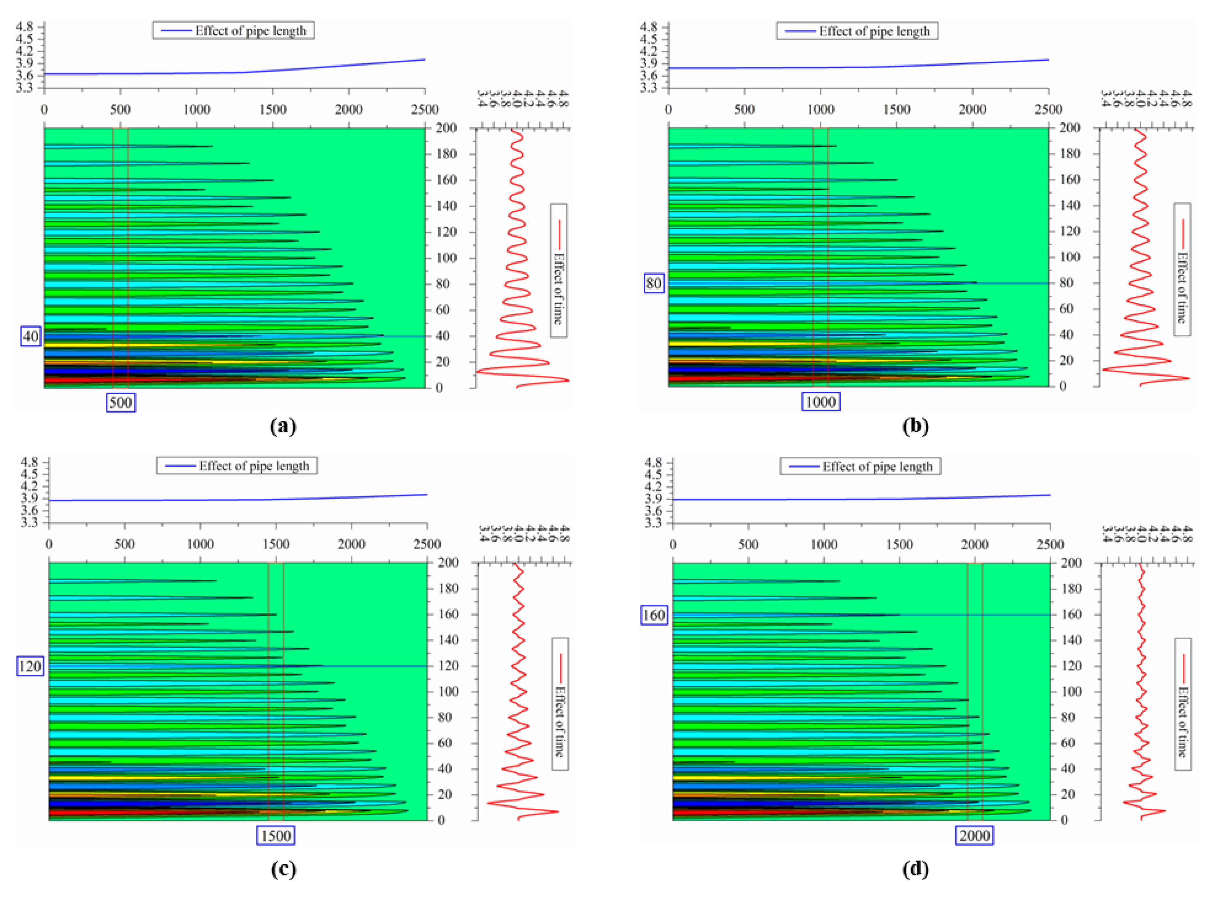
4.2. Result and Discussion

Assuming that the valve closing time is about 5 s, the valve closing index m is 1.0 (linear valve closing), and the calculation time is 200 s. Figure 6 is the change of pressure at the pipe end after valve closing. It can be seen from the figure that at the moment of valve closing, the fluid flow rate at the pipe end suddenly changes to 0, the pressure increases rapidly, reaches the peak value of 4.95 MPa at 5.08 s, then starts to decline, reaching the valley value of 3.37 MPa at 12.80 s. Due to friction along the way, the fluctuating pressure will decay quickly and finally reach the equilibrium pressure.
Take the section close to the pipe end as the research plane and calculate the fluctuation of velocity in this plane as shown in Figure 7. Before closing the valve, the initial flow velocity of the section is 2.85 m/s. When the valve is closed, the flow rate drops rapidly and fluctuates around 0. According to the principle of the Bernoulli equation, the fluctuation will become weaker and weaker over time. Finally, the fluid pressure in the pipe will be a certain value and the flow rate will be 0.
The effects of different valve closing time on the fluctuation of pressure and velocity at the pipe end are studied by the model. As shown in Figure 8a, the simulation results of fluctuating pressure at the pipe end under five different valve closing times are shown. According to the calculation, with the gradual increase of valve closing time, the maximum fluctuating pressure at the pipe end decreases, and the time of peak value lags behind. Figure 8b shows the simulation results of fluctuation velocity near the pipe end under five different valve closing times. The shorter the valve closing time, the earlier the flow rate drops to 0 and fluctuates around 0, and the greater the fluctuation range.
Figure 9 shows the influence of different flow rates on pipe end pressure. It can be seen from Figure 9a that the pressure at the pipe end first decreases and then increases at the moment of valve closing. When the flow in the pipe is 0.4 kg/s, the decline amplitude is the largest, but the rise speed is also the fastest and the peak value is the highest. Similarly, when the flow rate is 0.4 kg/s, the decline rate of pipe end pressure from peak to valley is the fastest and the valley is the smallest. That is, the greater the flow, the greater the change of pipe end pressure, the faster the speed change, and the more obvious the water hammer effect.
As Figure 9b shows, the greater the flow rate, the greater the initial flow velocity in the pipe and the fastest the decline rate of flow velocity. According to the enlarged view shown in Figure 9b, when the flow rate is large (e.g., flow rate is 0.4 kg/s), flow rate fluctuation is more intense. Moreover, there will be small fluctuations at inflection points such as falling from peak value and rising from valley value. The larger the flow, the more obvious the small fluctuations. It shows that the flow with large flow is greatly disturbed by instantaneous obstacles such as valve closing. However, with the increase of time, the impact of flow will be less and less obvious, whether it is pressure or flow rate.
After the fluctuating pressure is generated at the pipe end, it will propagate upstream along the pipeline to form a pressurization wave surface. To intuitively obtain the propagation of pressure wave in all calculation time, the three-dimensional diagram of pressure-wave propagation with pipe length and time after valve closing is drawn (Figure 10).
The effects of different pipe length and time on the fluctuating pressure in the pipe are studied, as shown in Figure 11. Figure 11a shows the pressure change chart in a 500 m section at 40 s. Pressure changes with pipe length when the blue line is 40 s. The red line shows the change of pressure with time at 500 m. By analogy, Figure 11b–d are the pressure change charts of a 1000 m section at 80 s, 1500 m section at 120 s and 2000 m section at 160 s after valve closing. The meaning of the blue line and the red line is the same as that in Figure 11a. It can be seen from the figure that the pressure fluctuation will gradually attenuate along the pipe length with the increase of time. The place with the greatest water hammer effect is near the valve. Under the coupling effect of time and tube length, the shorter the time and the shorter the tube length, the more obvious the pressure fluctuation; the longer the time and the longer the tube, the weaker the pressure fluctuation.
Through the water hammer model established in this paper, the changes of pipe end pressure and flow velocity under five conditions with gas content of 1%, 3%, 5%, 7% and 9% were calculated, respectively (Figure 12). Figure 12a shows that the greater the gas content, the smaller the fluctuation peak of pipe end pressure. The time of the first peak of pressure wave is basically the same, but the time of the first valley value begins to be different. The greater the gas content, the later the minimum pressure appears. With the increase of time, this difference becomes more and more obvious, which is reflected in a longer water hammer cycle. Since the water hammer period is the ratio of pipe length to pressure-wave velocity, the greater the void fraction, the smaller the pressure-wave velocity. Slightly different is that there is a difference in the time when the first fluctuation value of velocity wave appears. The greater the void fraction, the longer the time lag of flow rate fluctuation, as shown in Figure 12b. According to Bernoulli’s theory, pressure and velocity should be in a trade-off relationship and as the former increases, the latter decreases. Therefore, when the gas content is large, although the velocity fluctuation lags, the absolute value of velocity is large.
When there is free gas in the oil pipe, the gas will form uneven bubbles in the pipe. When the bubble is free in the oil, it can be approximately regarded as an elastic deformable body. When there is pressure fluctuation in the oil, the bubbles will be forced to compress and increase their internal energy. At this time, the bubbles are not stable, and work will be done to the surrounding oil to release energy, so that the momentum of the oil increases and compresses the surrounding bubbles. Due to energy dissipation, the increase of oil momentum is not equal to the increase of internal energy after bubble forcing, and the energy of bubble forcing comes from pressure fluctuation. Therefore, the actual pressure fluctuation value is obviously lower than that without gas, and the size of the pressure wave mainly depends on the gas content [36,37,38].

5. Conclusions

Based on the essence of water hammer, the interaction between pipeline fluid motion and water hammer wave propagation is considered, and the pressure, velocity, density and overflow area are set as variables. A new set of water hammer calculation equations is deduced and solved numerically. The effects of different valve closing time, flow rate and gas content on pressure distribution and water hammer effect were studied. The following conclusions can be drawn:
With the increase of valve closing time, the maximum fluctuating pressure at the pipe end decreases, and the time of peak value also lags behind. The shorter the valve closing time, the earlier the flow rate drops to zero and fluctuates around zero, and the greater the fluctuation range. When the valve closing time increases from 5 s to 25 s, the difference of water hammer pressure is 0.72 MPa and the difference of velocity fluctuation amplitude is 0.076 m/s.
With greater flow, the pressure change at the pipe end is greater. With faster speed changes, the water hammer effect becomes more obvious. With larger flow, flow velocity fluctuations increase, and there will be a small amplitude fluctuation. Our calculations show that the flow with large flow is greatly disturbed by instantaneous obstacles such as valve closing. However, with the increase of time, the impact of flow will be less and less obvious, whether it is pressure or flow rate.
With the increase of time, the pressure fluctuation will gradually attenuate along the pipe length. The place with the greatest water hammer effect is near the valve. Under the coupling effect of time and tube length, the shorter the time and the shorter the tube length, the more obvious the pressure fluctuation.
Our calculations show that the larger the gas content is, the smaller the fluctuation peak of pipe end pressure is, the longer the water hammer cycle is, and the smaller the pressure-wave velocity is. The actual pressure fluctuation value is obviously lower than that without gas, and the size of the pressure wave mainly depends on the gas content. When the gas content increases from 1% to 9%, the difference in water hammer pressure is 0.41 MPa. When the gas content is large, although the velocity fluctuation lags, the absolute value of velocity is large.

Author Contributions

Conceptualization, methodology, software, C.L.; investigation, J.J.; validation, formal analysis, writing—original draft preparation, writing—review and editing, J.D. All authors have read and agreed to the published version of the manuscript.

Funding

This research received no external funding.

Conflicts of Interest

The authors declare no conflict of interest.

Nomenclature

AFlow channel aream2
aPressure-wave velocitym/s
CgGas content%
DPipe diameterm
ePipe wall thicknessm
EElastic modulus of pipesMPa
fFriction coefficientdimensionless
gGravitational accelerationm/s2
HWater headm
iTime node numberdimensionless
kSpatial node numberdimensionless
KFluid compressibility coefficientdimensionless
moFluid momentumkg·m/s
pPressureMPa
QgGas flowkg/s
QlLiquid flowkg/s
ΔsDisplacement stepm
sLocationm
ΔtTime steps
tTimes
vFlow velocitym/s
vmGas-liquid mixing flow velocitym/s
xLength of flow sectionm
yMoving distancem
zPosition of reference pointm
ρFluid densitykg/m3
ρgGas densitykg/m3
ρlLiquid densitykg/m3
ρmMultiphase fluid densitykg/m3
θIncluded angle between pipeline axis and horizontal direction°
γSpecific gravitydimensionless
ξFitting coefficientdimensionless
χWet perimeterm
τ0Pipe inner wall shear stressMPa

References

  1. Ye, J.; Zeng, W.; Zhao, Z.; Yang, J.; Yang, J. Optimization of Pump Turbine Closing Operation to Minimize Water Hammer and Pulsating Pressures During Load Rejection. Energies 2020, 13, 1000. [Google Scholar] [CrossRef] [Green Version]
  2. Chen, S.; Zhang, J.; Li, G.; Yu, X. Influence Mechanism of Geometric Characteristics of Water Conveyance System on Extreme Water Hammer during Load Rejection in Pumped Storage Plants. Energies 2019, 12, 2854. [Google Scholar] [CrossRef] [Green Version]
  3. Kandil, M.; Kamal, A.M.; El-Sayed, T.A. Study the effect of pipematerials properties on the water hammer considering the fluid-structure interaction, frictionless model. Int. J. Press. Vessel. Pip. 2021, 104550. [Google Scholar] [CrossRef]
  4. Mery, H.O.; Hassan, J.M.; Ekaid, A.L. Viscoelastic loop strategy for water hammer control in a pressurized steel pipeline. Mater. Today Proc. 2021; in press. [Google Scholar] [CrossRef]
  5. Wylie, S. Transient Flow; Water Conservancy and Electric Power Press: Beijing, China, 1983. [Google Scholar]
  6. Garg, R.K.; Kumar, A. Experimental and numerical investigations of water hammer analysis in pipeline with two different materials and their combined configuration. Int. J. Press. Vessel. Pip. 2020, 188, 104219. [Google Scholar] [CrossRef]
  7. Behroozi, A.M.; Vaghefi, M. Numerical simulation of water hammer using implicit Crank-Nicolson Local Multiquadric Based Differential Quadrature. Int. J. Press. Vessel. Pip. 2020, 181, 104078. [Google Scholar] [CrossRef]
  8. Yang, J.; Lv, Y.; Liu, D.; Wang, Z. Pressure Analysis in the Draft Tube of a Pump-Turbine under Steady and Transient Conditions. Energies 2021, 14, 4732. [Google Scholar] [CrossRef]
  9. Zhang, L.; Zhang, J.; Yu, X.; Lv, J.; Zhang, X. Transient Simulation for a Pumped Storage Power Plant Considering Pressure Pulsation Based on Field Test. Energies 2019, 12, 2498. [Google Scholar] [CrossRef] [Green Version]
  10. Slawomir, H. Numerical modeling of water hammer with fluid–structure interaction in a pipeline with viscoelastic supports. J. Fluids Struct. 2018, 76, 469–487. [Google Scholar]
  11. Baba, G.A.; Norsarahaida, A. The Effect of Water Hammer on Pressure Oscillation of Hydrogen Natural Gas Transient Flow. Appl. Mech. Mater. 2014, 554, 251–255. [Google Scholar] [CrossRef]
  12. Wahba, E.M. On the Propagation and Attenuation of Turbulent Fluid Transients in Circular Pipes. J. Fluids Eng. 2015, 138, 031106. [Google Scholar] [CrossRef]
  13. Kandil, M.; Kamal, A.M.; El-Sayed, T.A. Effect pipes material on water hammer. Int. J. Press. Vessel. Pip. 2019, 179, 103996. [Google Scholar] [CrossRef]
  14. Abdel-Gawad, H.A.A.; Djebedjian, B. Modeling water hammer in viscoelastic pipes using the wave characteristic method. Appl. Math. Model. 2020, 83, 322–341. [Google Scholar] [CrossRef]
  15. Khamoushi, A.; Keramat, A.; Majd, A. One-Dimensional Simulation of Transient Flows in Non-Newtonian Fluids. J. Pipeline Syst. Eng. Pract. 2020, 11, 04020019. [Google Scholar] [CrossRef]
  16. Abdeldayem, O.M.; Ferràs, D.; van der Zwan, S.; Kennedy, M. Analysis of Unsteady Friction Models Used in Engineering Software for Water Hammer Analysis: Implementation Case in WANDA. Water 2021, 13, 495. [Google Scholar] [CrossRef]
  17. Lashkarbolok, M.; Tijsseling, A.S. Numerical simulation of water-hammer in tapered pipes using an implicit least-squares approach. Int. J. Press. Vessel. Pip. 2020, 187, 104161. [Google Scholar] [CrossRef]
  18. Aliabadi, H.K.; Ahmadi, A.; Keramat, A. Frequency response of water hammer with fluid-structure interaction in a viscoelastic pipe. Mech. Syst. Signal Process. 2020, 144, 106848. [Google Scholar] [CrossRef]
  19. Firouzi, A.; Yang, W.; Shi, W.; Li, C.Q. Failure of corrosion affected buried cast iron pipes subject to water hammer. Eng. Fail. Anal. 2021, 120, 104993. [Google Scholar] [CrossRef]
  20. Henclik, S. Application of the shock response spectrum method to severity assessment of water hammer loads. Mech. Syst. Signal Process. 2021, 157, 107649. [Google Scholar] [CrossRef]
  21. Chen, T.; Su, Z.; Zhu, J.; Li, M. Analysis and improvement of 4-equation based on FSI. Chin. J. Appl. Mech. 2016, 33, 565–569. [Google Scholar]
  22. Zhu, Y.; Wu, C.; Yuan, Y.; Shi, Z. Experimental and modeling study on gas-liquid two-phase transient flow in viscoelastic pipes. J. Harbin Inst. Technol. 2018, 50, 89–93+172. [Google Scholar]
  23. Zhu, Y.; Wu, C.; Yuan, Y.; Shi, Z. Analysis of pressure damping in air-water transient flow in viscoelastic pipes. J. Hydraul. Eng. 2018, 49, 303–312. [Google Scholar]
  24. Fu, Y.; Jiang, J.; Li, Y.; Ying, R. Calculation of pipe water hammer pressure with liquid column separation by improved two-fluid model. Trans. Chin. Soc. Agric. Eng. 2018, 34, 58–65. [Google Scholar]
  25. Fu, Y.; Jiang, J.; Li, Y.; Ying, R. Water hammer simulated method based on two-fluid model in two-phase flow. J. Huazhong Univ. Sci. Technol. 2018, 46, 126–132. [Google Scholar]
  26. Han, K.; Ding, F.; Mao, Z. Solving water column separation and cavity collapse for pipelines by semi-analytical method. Trans. Chin. Soc. Agric. Eng. 2019, 35, 33–39. [Google Scholar]
  27. Twyman, J. Transient flow analysis using the method of characteristics MOC with five-point interpolation scheme. Obras Proy. 2018, 24, 62–70. [Google Scholar] [CrossRef] [Green Version]
  28. Fan, L.; Wang, F.; Li, H. Characteristic-line-based model predictive control for hyperbolic distributed parameter systems and its application. Control. Theory Appl. 2013, 30, 1329–1334. [Google Scholar]
  29. Napolitano, M. Computational fluid dynamics in Europe, a personal view. Acta Aerodyn. Sin. 2016, 34, 139–156. [Google Scholar]
  30. Zhang, D. Discrete integrable systems: Multidimensional consistency. Acta Phys. Sin. 2020, 69, 010202. [Google Scholar] [CrossRef]
  31. Zhang, Z.; Wang, J.; Li, Y.; Liu, H.; Meng, W.; Li, L. Research on the Influence of Production Fluctuation of High-Production Gas Well on Service Security of Tubing String. Oil Gas Sci. Technol. 2021, 76, 54. [Google Scholar] [CrossRef]
  32. Nerella, R.; Rathnam, E.V. Fluid Transients and Wave Propagation in Pressurized Conduits Due to Valve Closure. Procedia Eng. 2015, 127, 1158–1164. [Google Scholar] [CrossRef] [Green Version]
  33. Henclik, S. A Numerical Approach to the Standard Model of Water Hammer with Fluid-Structure Interaction. J. Teor. Appl. Mech. 2015, 53, 543–555. [Google Scholar] [CrossRef] [Green Version]
  34. Tomaszewski, A.; Przybylinski, T.; Lackowski, M. Experimental and Numerical Analysis of Multi-Hole Orifice Flow Meter: Investigation of the Relationship between Pressure Drop and Mass Flow Rate. Sensors 2020, 20, 7281. [Google Scholar] [CrossRef] [PubMed]
  35. Ismaier, A.; Schluecker, E. Fluid dynamic interaction between water hammer and centrifugal pumps. Nucl. Eng. Des. 2009, 239, 3151–3154. [Google Scholar] [CrossRef]
  36. Zolfaghary, A.H.; Naghashzadegan, M.; Shokri, V. Comparison of Numerical Methods for Two-Fluid Model for Gas–Liquid Transient Flow Regime and Its Application in Slug Modeling Initiation. Iran. J. Sci. Technol. Trans. Mech. Eng. 2018, 43, 663–673. [Google Scholar] [CrossRef]
  37. Zhai, L.; Yang, J.; Wang, Y. An investigation of transition processes from transient gas–liquid plug to slug flow in horizontal pipe: Experiment and Cost-based recurrence analysis. Nucl. Eng. Des. 2021, 379, 111253. [Google Scholar] [CrossRef]
  38. Sondermann, C.N.; Freitas, R.; Rachid, F.; Bodstein, G. A suitability analysis of transient one-dimensional two-fluid numerical models for simulating two-phase gas-liquid flows based on benchmark problems. Comput. Fluids 2021, 229, 105070. [Google Scholar] [CrossRef]
Figure 1. The fluid movement state in the pipe after the valve is suddenly closed (ignoring friction) [10].
Energies 15 01387 g001
Figure 2. Schematic diagram of water hammer wave propagation.
Energies 15 01387 g002
Figure 3. L-t plane of characteristic grid.
Energies 15 01387 g003
Figure 4. Flowchart of calculation of water hammer four variable closed model.
Energies 15 01387 g004
Figure 5. Comparison between calculation results of the present model and literature results.
Energies 15 01387 g005
Figure 6. Pressure fluctuation at the end of the pipeline.
Energies 15 01387 g006
Figure 7. Difference of natural frequency of tubing under two model analysis methods.
Energies 15 01387 g007
Figure 8. Influence of valve closing time on pressure and velocity fluctuation at the end of a pipeline: (a) represents pressure response; (b) represents velocity response.
Energies 15 01387 g008
Figure 9. Influence of flow rate on pressure and velocity fluctuation at the end of a pipeline: (a) represents pressure response; (b) represents velocity response.
Energies 15 01387 g009
Figure 10. Three-dimensional diagram of pressure-wave propagation with pipe length and time after valve closing: (a) represents pressure response; (b) represents velocity response.
Energies 15 01387 g010
Figure 11. Effect of different pipe length and time on fluctuating pressure in pipe: (a) represents the pressure change chart in a 500 m section at 40 s; (b) represents the pressure change chart in a 1000 m section at 80 s; (c) represents the pressure change chart in a 1500 m section at 120 s; (d) represents the pressure change chart in a 2000 m section at 160 s.
Energies 15 01387 g011
Figure 12. Influence of gas content on pressure and velocity fluctuation at the end of a pipeline: (a) represents pressure response; (b) represents velocity response.
Energies 15 01387 g012
Table 1. Physical parameters of oil, soil, anticorrosion coating and pipe.
ParameterValueParameterValue
Density of oil841 kg/cm3Specific heat of soil2225 J/(K·kg)
Thermal diffusivity of oil5.91 mm2/sSpecific heat of pipe465 J/(K·kg)
Thermal conductivity of oil0.162 W/(m·K)Specific heat of anticorrosive coating2000 J/(K·kg)
Coefficient of thermal expansion of oil8.3 × 10−4 K−1Specific heat of oil1900 J/(K·kg)
Density of soil1455 kg/cm3Thermal conductivity of soil1.4 W/(m·K)
Density of pipe7850 kg/cm3Thermal conductivity of pipe48 W/(m·K)
Density of anticorrosive coating1200 kg/cm3Thermal conductivity of anticorrosive coating0.15 W/(m·K)
Publisher’s Note: MDPI stays neutral with regard to jurisdictional claims in published maps and institutional affiliations.

