
Stress and Pressure Pulsation Analysis of Low Temperature Compressor Piping System in LNG Vaporizing Station

Abstract
:1. Introduction
2. Basic Theories
2.1. Plan Wave Theory
- (1)
- Continuity equation
- (2)
- Motion equation
- (3)
- Wave equation
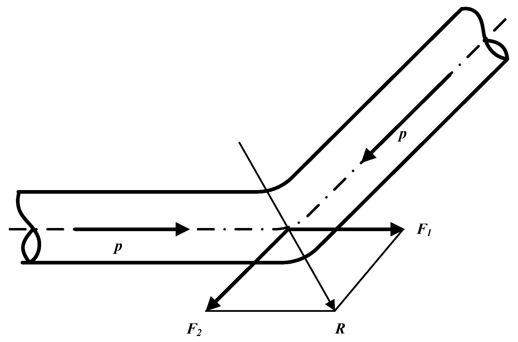
2.2. Pressure Pulsation and Unbalanced Exciting Force
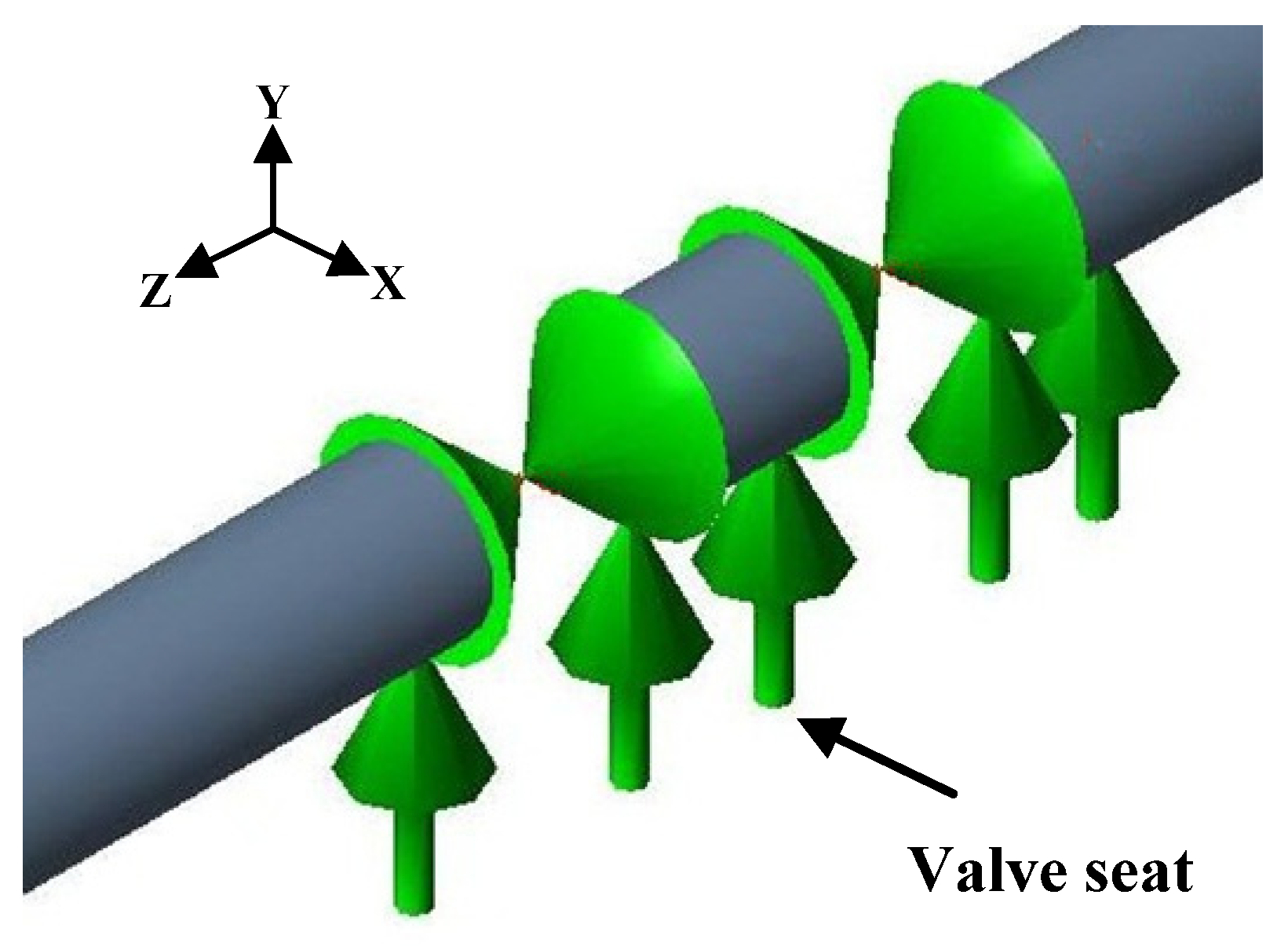
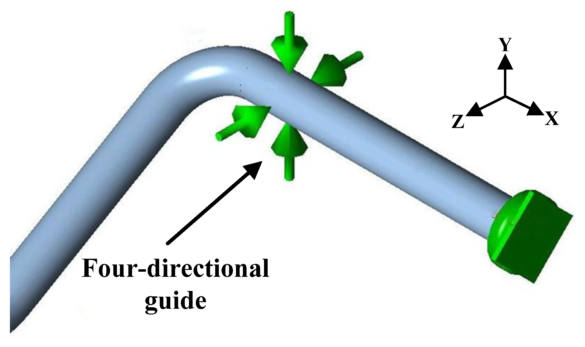
2.3. Model of Pipe and Constraints
2.4. Stress Analysis Method
- 1.
- Assumed condition
- (a)
- The assumption of small deformation: in the cross section, the local deformation of the element under load is negligible;
- (b)
- The plastic deformation and large deformation are not considered in the elastic range of the pipe material, which means the nonlinear problem of the pipe structure is not taken into account;
- (c)
- In the process of loading the aircraft remains flat;
- (d)
- Considering only the elastic changes and loads of the pipe, and Hooke’s law applies to the full load range of the tubular section;
- (e)
- Assuming that the points, the forces and moments acting on the structure are on their central axes;
- (f)
- The rotational deformation of the system is small;
- (g)
- The force is not affected by structural deformation.
- 2.
- Grid precision
- 3.
- Mass matrix of piping system
2.5. Natural Frequency and Excitation Frequency
2.6. Pipe Stress and Model Calibration
- Stress calibration
- 2.
- Model calibration
3. Case Study
3.1. Project Overview
3.2. Numerical Simulation
4. Results
4.1. Static Stress Analysis Result
- 1.
- Stress analysis result
- a.
- The stress distribution of the same type of pipe is basically the same, and the larger stress is produced at the tee or the elbow.
- b.
- The comprehensive stress of each pipe is the largest, the secondary stress is slightly less than the comprehensive stress, and the primary stress is the smallest. It shows that the temperature difference (Secondary stress) had the greatest influence on the pipe stress for the low-temperature pipeline in the LNG vaporizing station.
- c.
- The stress of compressor inlet pipe is slightly greater than the compressor outlet pipe, the stress of main suction pipe is slightly larger than the main exhaust pipe (The temperature of BOG in the compressor inlet pipe and main suction pipe is lower than the compressor inlet pipe and main exhaust pipe, but the pressure of compressor outlet pipe and main exhaust pipe is larger), indicating that the impact of temperature difference on the stress is greater than the impact of pressure.
- 2.
- Displacement analysis
- a.
- The horizontal displacement of the pipe was restricted by the bracket and support, so the horizontal displacement of the pipe was the smallest.
- b.
- Compressor inlet pipe and main suction pipe experienced larger negative axial displacements and longitudinal displacements, and the displacement was recorded to be as high as 70 mm because the low temperature of BOG in the pipe, which caused the cold contraction of the pipe.
4.2. Harmonic Analysis Result
- RC1 runs separately
- 2.
- RC1 and RC2 run together
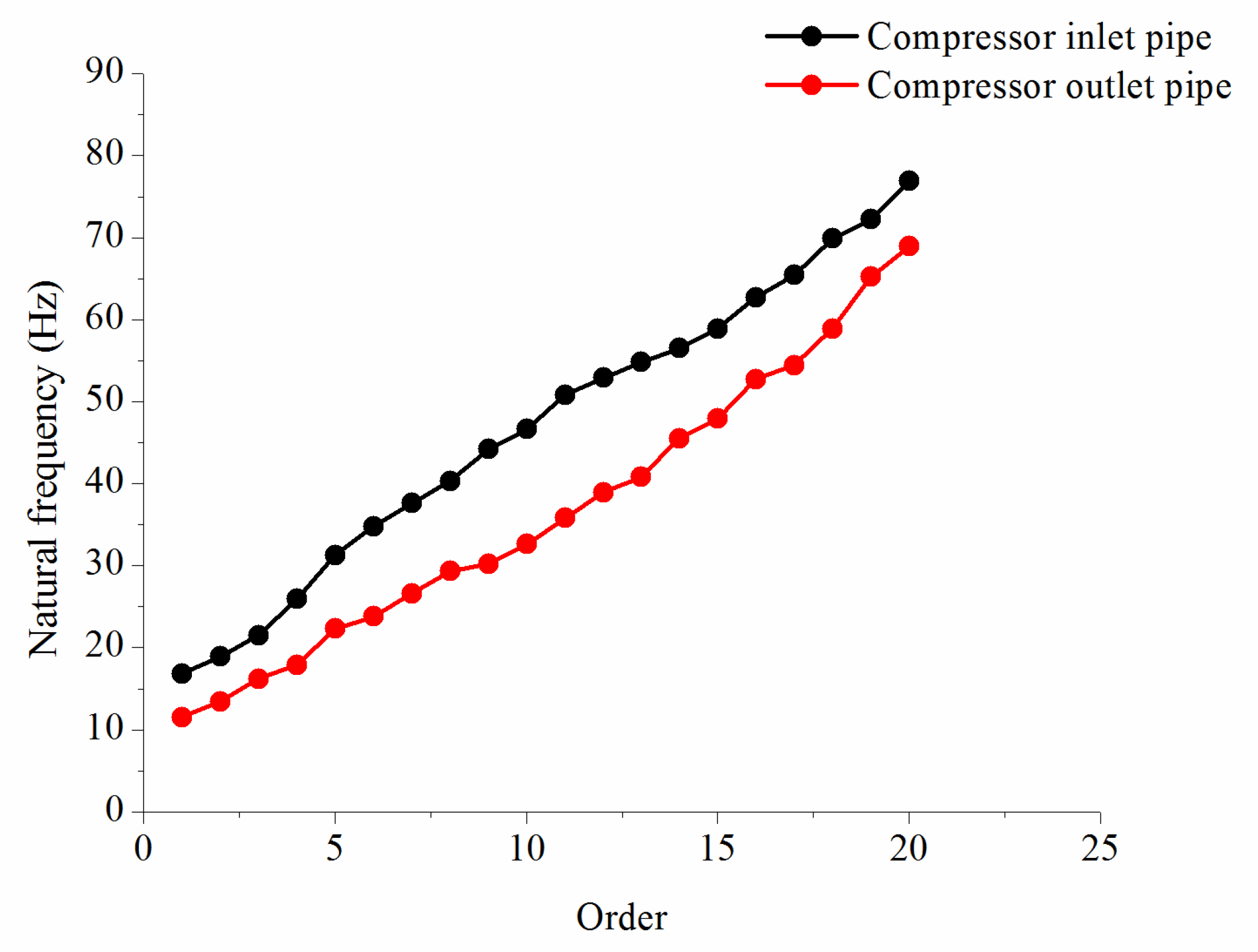
4.3. Modal Analysis Result
5. Discussion
5.1. Influence of Pipe Support Spacing
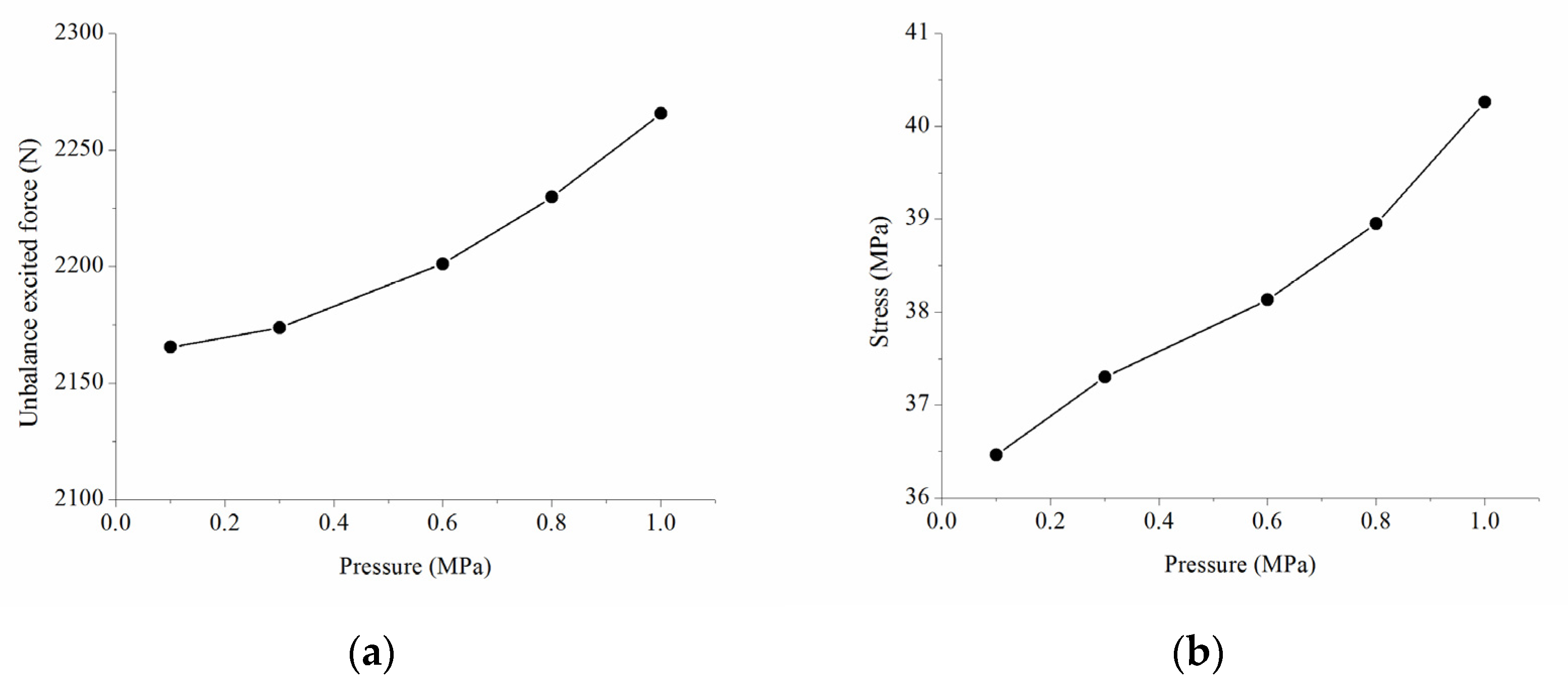
5.2. Influence of Pressure
5.3. Influence of Elbow Angle
5.4. Stress Reduction Measures
- Add constraint
- 2.
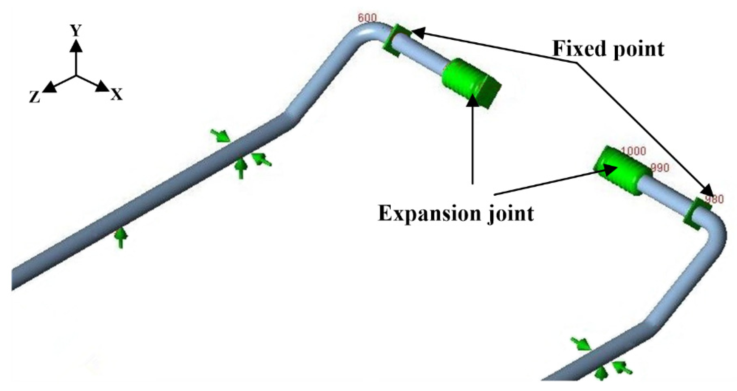
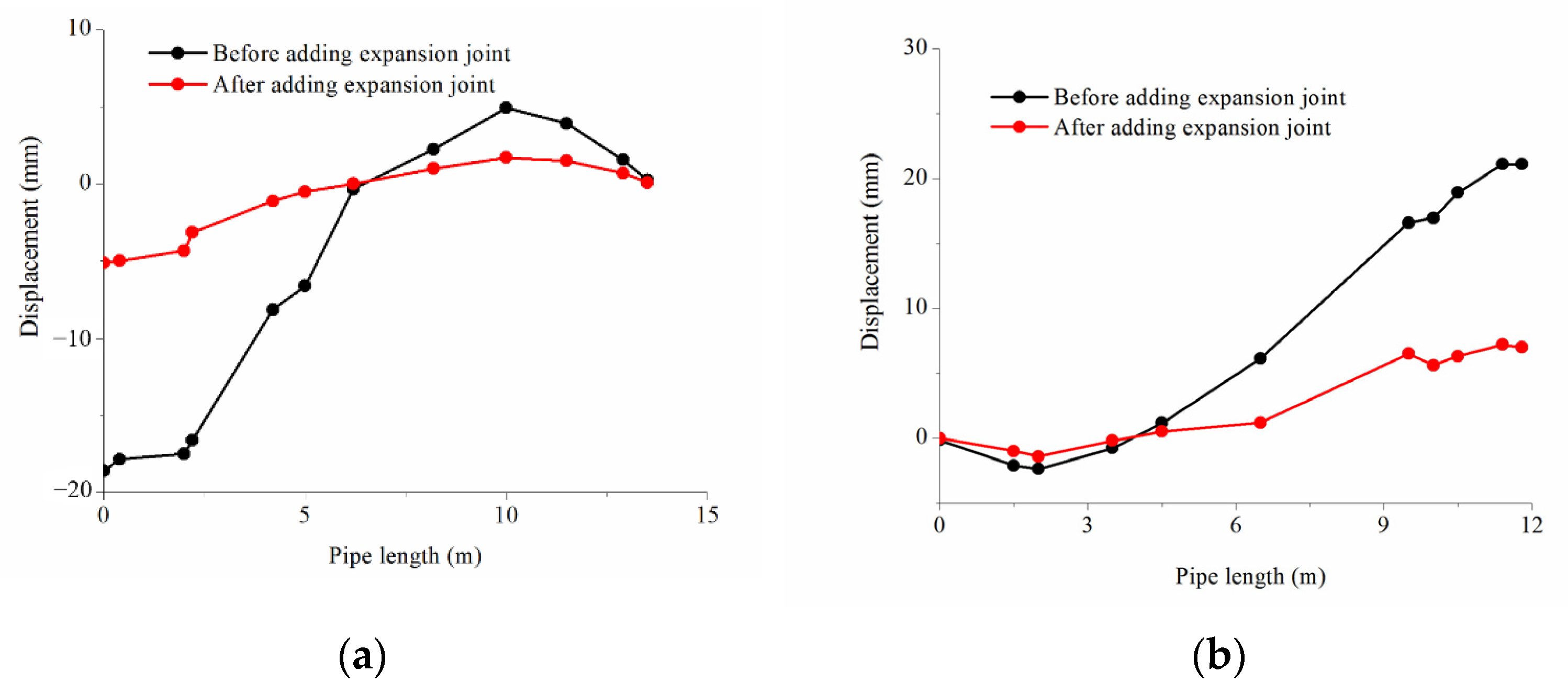
- Set expansion joint
6. Conclusions
- For a BOG compressor piping system which belongs to low-temperature piping system, the secondary stress is much larger than the primary stress, indicating that the temperature difference plays a leading role in the stress of low-temperature pipes.
- The unbalanced exciting force has great influence on the stress of the compressor outlet pipe and the main exhaust pipe, and has little influence on the stress of the compressor inlet pipe and the main suction pipe.
- Although unbalanced exciting forces are produced at the elbows and the tees, the stresses of the elbows and the tees are greatly influenced, which also has a certain impact on the straight pipes.
- The pipe stress is not only influenced by the unbalanced exciting force, but by the structure of pipe itself.
- Adding constraints or expansion joints can effectively reduce the pipe stress.
Author Contributions
Funding
Institutional Review Board Statement
Informed Consent Statement
Data Availability Statement
Conflicts of Interest
References
- Xu, Z.-D.; Shen, Y.-P.; Guo, Y.-Q. Semi-active control of structures incorporated with magnetorheological dampers using neural networks. Smart Mater. Struct. 2003, 12, 80–87. [Google Scholar] [CrossRef]
- Xu, Z.-D.; Liao, Y.X.; Ge, T.; Xu, C. Experimental and Theoretical Study of Viscoelastic Dampers with Different Matrix Rubbers. J. Eng. Mech. 2016, 142, 04016051. [Google Scholar] [CrossRef]
- Lu, H.; Xu, Z.-D.; Azimi, M.; Fu, L.; Wang, Y. An Effective Data-Driven Model for Predicting Energy Consumption of Long-Distance Oil Pipelines. J. Pipeline Syst. Eng. Pract. 2022, 13, 04022005. [Google Scholar] [CrossRef]
- Lu, H.; Iseley, T.; Matthews, J.; Liao, W. Hybrid machine learning for pullback force forecasting during horizontal directional drilling. Autom. Constr. 2021, 129, 103810. [Google Scholar] [CrossRef]
- Xu, Z.-D.; Jia, D.-H.; Zhang, X.-C. Performance tests and mathematical model considering magnetic saturation for magnetorheological damper. J. Intell. Mater. Syst. Struct. 2012, 23, 1331–1349. [Google Scholar] [CrossRef]
- GB/T 20801; Pressure Piping Code Industrial Piping Part 1: General. China Standardization Committee on Boilers and Pressure Vessels: Beijing, China, 2006.
- Chilton, E.G.; Handley, L. Pulsations in gas compressor systems. Trans. ASME 1952, 45, 214–218. [Google Scholar]
- Sun, S.Y.; Ren, T.R.; Shi, Y.M.; Cui, T.S. Optimum disposition of assembled piping system for parallel operation of multiple compressors. Int. J. Press. Vessel. Pip. 1996, 68, 145–151. [Google Scholar]
- Attenuation of Gas Pulsations Using A Perforated Tube. Available online: https://docs.lib.purdue.edu/icec/237 (accessed on 20 December 2021).
- Shin, Y.W.; Wiedermann, A.H. A Method for Suppression of Pressure Pulses in Fluid-Filled Piping—Part I: Theoretical Analysis. J. Press. Vessel Technol. 1992, 114, 60–65. [Google Scholar] [CrossRef]
- Shin, Y.W.; Bielick, E.F.; Wiedermann, A.H.; Ockert, C.E. A Method for Suppression of Pressure Pulse in Fluid-Filled Piping—Part II: Experimental Verification. J. Press. Vessel Technol. 1992, 114, 66–73. [Google Scholar] [CrossRef]
- Chen, L.L.; Xie, Z.N. A research for the optimization of the vibrating excitation in reciprocating compressor piping system. Chin. J. Appl. Mech. 1995, 12, 102–105. [Google Scholar]
- Chen, L.L.; Wang, R.; Xu, J.X. A study on the dynamic optimum of the supported stiffness for piping structure in reciprocating compressor systems. J. Xi’an Jiaotong Univ. 1996, 30, 95–100. [Google Scholar]
- Cheng, M.G. Vibration analysis and vibration reduction for inlet of water filling pump. Petro-Chem. Equip. Technol. 1995, 16, 51–52. [Google Scholar]
- Xing, K.L.; Ge, S.H.; Ding, C.S.; He, R. Theoretical analysis of a new serial pocket-type accumulator. Constr. Machin. Equip. 1997, 28, 24–26. [Google Scholar]
- Zhang, H.J. Vibration analysis and modification measures for piping of reciprocating pump. Chem. Eng. Design 2000, 10, 12–15. [Google Scholar]
- Xie, P.A.; Wang, Q. Study on attenuation of fluid-borne pulsation using accumulator. Noise Vib. Control 2000, 4, 2–5. [Google Scholar]
- Wang, Q.; Shen, R.Y.; Yao, B.Y.; Ding, W. Attenuation of vibration and pulsating pressure of pipeline using pipe attenuator. Shipbuild. China 2003, 44, 39–45. [Google Scholar]
- Xue, W.F. The Study on Vibration and Vibration Control of the Pipeline of Reciprocating Compressor. Master’s Thesis, Fuzhou University, Fujian, China, 2003. [Google Scholar]
- Xiao, G.M. The Research on Vibration Control of the Pipeline of Piston Compressor. Master’s Thesis, Southwest Jiaotong University, Chengdu, China, 2006. [Google Scholar]
- Yu, C.L.; Wei, Y.; Hu, X.M. Piping vibration analysis for the type of reciprocating compressor. China Offshore Platf. 2007, 22, 52–56. [Google Scholar]
- Chen, H.F. Study on Vibration Characteristics and Safety Evaluation of Reciprocating Compressor Pipeline. Master’s Thesis, China University of Petroleum, Qingdao, China, 2009. [Google Scholar]
- Sui, K.; Wang, J. Calculation and analysis on residential pipeline pressure pulsation. Environ. Technol. 2013, z1, 203–206. [Google Scholar]
- Lu, H.; Huang, K.; Wu, S. Vibration and Stress Analyses of Positive Displacement Pump Pipeline Systems in Oil Transportation Stations. J. Pipeline Syst. Eng. Pract. 2016, 7, 05015002. [Google Scholar] [CrossRef]
- Su, P.; Liu, Y.H.; Wang, Z.Y.; Wang, Y.B. Finite element numerical simulation on thermal stress distribution of LNG pipeline. Contemp. Chem. Industry 2013, 42, 1198–1200. [Google Scholar]
- Liu, H.F.; Xu, H.Z. The LNG pipe stress calculation and analysis. Chem. Ind. Times 2013, 27, 21–22. [Google Scholar]
- Yu, G.P.; Zhao, G.M.; Zhang, Y.X. Stress analysis of low temperature pipeline in LNG tank area. Petro-Chem. Design 2015, 32, 22–25. [Google Scholar]
- Xu, Q.; Liu, C.; Wang, X.; Cao, Y.; Yu, H.; Li, W.; Guo, L. Machine learning classification of flow regimes in a long pipeline-riser system with differential pressure signal. Chem. Eng. Sci. 2021, 233, 116402. [Google Scholar] [CrossRef]
- Xu, Q.; Liang, L.; She, Y.; Xie, X.; Guo, L. Numerical investigation on thermal hydraulic characteristics of steam jet condensation in subcooled water flow in pipes. Int. J. Heat Mass Transf. 2022, 184, 122277. [Google Scholar] [CrossRef]
- Hwang, S.-Y.; Kim, M.-S.; Lee, J.-H. Thermal Stress Analysis of Process Piping System Installed on LNG Vessel Subject to Hull Design Loads. J. Mar. Sci. Eng. 2020, 8, 926. [Google Scholar] [CrossRef]
- American Petroleum Institute. Reciprocating Compressors for Petroleum, Chemical, and Gas Industry Services; API 618; American Petroleum Institute: Washington, DC, USA, 2007. [Google Scholar]
- Lu, H.; Wu, X.; Ni, H.; Azimi, M.; Yan, X.; Niu, Y. Stress analysis of urban gas pipeline repaired by inserted hose lining method. Compos. Part B Eng. 2020, 183, 107657. [Google Scholar] [CrossRef]
- Xu, Z.-D.; Wang, D.-X.; Shi, C.-F. Model, tests and application design for viscoelastic dampers. J. Vib. Control 2011, 17, 1359–1370. [Google Scholar] [CrossRef]
- Xu, Z.-D.; Yang, Y.; Miao, A.-N. Dynamic Analysis and Parameter Optimization of Pipelines with Multidimensional Vibration Isolation and Mitigation Device. J. Pipeline Syst. Eng. Pract. 2021, 12, 04020058. [Google Scholar] [CrossRef]
- Xu, Z.-D.; Zhu, C.; Shao, L.-W. Damage Identification of Pipeline Based on Ultrasonic Guided Wave and Wavelet Denoising. J. Pipeline Syst. Eng. Pract. 2021, 12, 04021051. [Google Scholar] [CrossRef]
- George, M. Pipe Stress Analysis Theory Guide; COADE Inc., China Technical Service and Training Center: Beijing, China, 1998. [Google Scholar]
- ASME. Process Piping; B31.3; ASME: New York, NY, USA, 2013. [Google Scholar]
- Song, K.K. Industrial Pipe Stress Analysis and Engineering Applications; Press of China Petrochemical: Beijing, China, 2011. [Google Scholar]
- Xu, Z.-D.; Gai, P.-P.; Zhao, H.-Y.; Huang, X.-H.; Lu, L.-Y. Experimental and theoretical study on a building structure controlled by multi-dimensional earthquake isolation and mitigation devices. Nonlinear Dyn. 2017, 89, 723–740. [Google Scholar] [CrossRef]
- Lu, H.; Xu, Z.-D.; Iseley, T.; Matthews, J.C. Novel Data-Driven Framework for Predicting Residual Strength of Corroded Pipelines. J. Pipeline Syst. Eng. Pract. 2021, 12, 04021045. [Google Scholar] [CrossRef]
- Lu, H.; Iseley, T.; Matthews, J.; Liao, W.; Azimi, M. An ensemble model based on relevance vector machine and multi-objective salp swarm algorithm for predicting burst pressure of corroded pipelines. J. Pet. Sci. Eng. 2021, 203, 108585. [Google Scholar] [CrossRef]
- Xu, Z.-D.; Xu, F.-H.; Chen, X. Vibration suppression on a platform by using vibration isolation and mitigation devices. Nonlinear Dyn. 2016, 83, 1341–1353. [Google Scholar] [CrossRef]
- Lu, H.F. Stress and Vibration Analysis of Reciprocating Pump Piping Systems. Master’s Thesis, Southwest Petroleum University, Chengdu, China, 2016. [Google Scholar]


| Pipe Type | Main Suction Pipe | Main Exhaust Pipe | Compressor Inlet Pipe | Compressor Outlet Pipe |
|---|---|---|---|---|
| Material | 06Cr19Ni10 | 06Cr19Ni10 | 06Cr19Ni10 | 06Cr19Ni10 |
| Diameter (mm) | 219 | 219 | 219 | 219 |
| Thickness (mm) | 6.0 | 6.0 | 6.0 | 6.0 |
| Insulation thickness (mm) | 30 | 30 | 30 | 30 |
| Fluid density (kg/m3) | 0.75 | 0.75 | 0.75 | 0.75 |
| Installation temperature (°C) | 20 | 20 | 20 | 20 |
| Operation temperature (°C) | −152 | −68 | −152 | −68 |
| Operation pressure (MPa) | 0.115 | 0.6 | 0.115 | 0.6 |
| Pipe Type | Location | Pressure Pulsation (Pa) | Unbalanced Exciting Force (N) | Direction | Phase Angle (Degree) |
|---|---|---|---|---|---|
| Compressor inlet pipe | RC1-B1 | 67,394.59 | −3207.53 | X | 0 |
| RC1-B2 | 117,453.19 | −2046.08 | Z | 3.21 | |
| RC1-B3 | 402,706.47 | 19,166.12 | Y | 15.42 | |
| Compressor outlet pipe | RC1-B4 | 46,248.18 | 2201.10 | X | 0 |
| RC1-B5 | 80,599.89 | −1404.08 | Z | 2.21 | |
| RC1-B6 | 247,275.66 | 11,768.66 | Y | 10.89 | |
| Main suction pipe | T1 | 415,325.64 | −19,766.71 | Z | 16.04 |
| Main exhaust pipe | T2 | 250,621.06 | −11,927.87 | Z | 11.73 |
| Pipe Type | Location | Pressure Pulsation (Pa) | Unbalanced Exciting Force (N) | Direction | Phase Angle (Degree) |
|---|---|---|---|---|---|
| Compressor inlet pipe | RC1-B1 | 67,391.59 | −3207.53 | X | 0 |
| RC1-B2 | 117,453.19 | −2046.07 | Z | 3.21 | |
| RC1-B3 | 402,706.47 | 19,166.12 | Y | 15.42 | |
| Compressor outlet pipe | RC1-B4 | 46,248.18 | 2201.10 | X | 0 |
| RC1-B5 | 80,599.89 | −1404.08 | Z | 2.21 | |
| RC1-B6 | 247,275.69 | 11,768.66 | Y | 10.89 | |
| Main suction pipe | T3 | 415,325.64 | −19,766.71 | Z | 16.04 |
| Main exhaust pipe | T4 | 254,731.38 | −12,123.50 | Z | 11.73 |
| Pipe Type | Maximum Stress (MPa) | Location | Allowable Stress (MPa) |
|---|---|---|---|
| RC1 compressor inlet pipe | 31.76 | RC1-B1 | 205.5 |
| RC1 compressor outlet pipe | 31.85 | RC1-B4 | |
| RC2 compressor inlet pipe | 34.14 | RC2-B1 | |
| RC2 compressor outlet pipe | 44.91 | RC2-B4 | |
| Main suction pipe | 105.99 | T1 | |
| Main exhaust pipe | 108.50 | T4 |
| Parameter | Content |
|---|---|
| Cut-off frequency | 200 HZ |
| Mass model | Lumped mass model |
| Estimated value of the effective number of the eigenvalues | 8 |
| Jacobi scanning tolerance | 10−12 |
| Decomposition singular tolerance | 1010 |
| Frequency array space | 100 |
| Variable | Spacing (mm) | Stress (MPa) |
|---|---|---|
| x | 400 | 39.76 |
| 600 | 37.6 | |
| 800 | 36.04 | |
| 1000 | 38.13 | |
| 1200 | 40.52 | |
| y | 1000 | 37.53 |
| 1500 | 37.75 | |
| 2000 | 38.13 | |
| 2500 | 38.24 | |
| 3000 | 39.49 |
| Elbow Angle (Degree) | Pressure Pulsation (Pa) at RC1-B5 | Unbalanced Exciting Force at RC1-B5 (N) | Stress of RC1-B4 (MPa) |
|---|---|---|---|
| 30 | 80,599.89 | −1404.08 | 38.13 |
| 35 | 80,599.89 | −1631.31 | 39.49 |
| 40 | 80,599.89 | −1855.44 | 39.16 |
| 45 | 80,599.89 | −2076.04 | 40.51 |
| 50 | 80,599.89 | −2292.68 | 42.73 |
| 55 | 80,599.89 | −2504.96 | 39.04 |
| 60 | 80,599.89 | −2712.47 | 34.92 |
| 65 | 80,599.89 | −2914.82 | 39.71 |
| 70 | 80,599.89 | −3111.62 | 42.43 |
| 75 | 80,599.89 | −3302.49 | 45.07 |
| 80 | 80,599.89 | −3487.08 | 47.91 |
| 85 | 80,599.89 | −3665.04 | 48.30 |
| 90 | 80,599.89 | −3836.01 | 49.46 |
| Position of Constraint | Constraint Type | Constraint Expression | Stress before Adding Constraint (MPa) | Stress after Adding Constraint (MPa) | Stress Reduction Factor KR |
|---|---|---|---|---|---|
| R1 | Unidirectional constraint | +Y | 105.68 | 126.21 | 0.19 |
| R2 | +Y | 103.96 | −0.02 | ||
| R3 | +Y | 91.63 | −0.13 | ||
| R4 | +Y | 96.75 | −0.08 | ||
| R5 | +Y | 102.80 | −0.03 | ||
| R1 | Three-direction constraint | +Y, +Z, −Z | 105.68 | 133.48 | 0.26 |
| R2 | +Y, +Z, −Z | 101.47 | −0.04 | ||
| R3 | +Y, +Z, −Z | 86.32 | −0.18 | ||
| R4 | +Y, +Z, −Z | 97.05 | −0.08 | ||
| R5 | +Y, +Z, −Z | 100.52 | −0.05 |
| Axial Stiffness (N/mm) | Stress before Adding Expansion Joint (MPa) | Stress after Adding Expansion Joint (MPa) | Stress Reduction Factor KR |
|---|---|---|---|
| 200 | 38.13 | 25.93 | −0.32 |
| 300 | 30.89 | −0.19 | |
| 400 | 35.08 | −0.08 | |
| 500 | 36.60 | −0.04 | |
| 600 | 36.61 | −0.04 |
Publisher’s Note: MDPI stays neutral with regard to jurisdictional claims in published maps and institutional affiliations. |
© 2022 by the authors. Licensee MDPI, Basel, Switzerland. This article is an open access article distributed under the terms and conditions of the Creative Commons Attribution (CC BY) license (https://creativecommons.org/licenses/by/4.0/).
Share and Cite
Wang, B.; Zhang, Z.; Huang, K.; Zhang, Y.; Zhang, Z.; Gao, H.; Fu, L. Stress and Pressure Pulsation Analysis of Low Temperature Compressor Piping System in LNG Vaporizing Station. Energies 2022, 15, 1874. https://0-doi-org.brum.beds.ac.uk/10.3390/en15051874
Wang B, Zhang Z, Huang K, Zhang Y, Zhang Z, Gao H, Fu L. Stress and Pressure Pulsation Analysis of Low Temperature Compressor Piping System in LNG Vaporizing Station. Energies. 2022; 15(5):1874. https://0-doi-org.brum.beds.ac.uk/10.3390/en15051874
Chicago/Turabian StyleWang, Baoqing, Zhi Zhang, Kun Huang, Yaotong Zhang, Zhenwu Zhang, Hui Gao, and Lingdi Fu. 2022. "Stress and Pressure Pulsation Analysis of Low Temperature Compressor Piping System in LNG Vaporizing Station" Energies 15, no. 5: 1874. https://0-doi-org.brum.beds.ac.uk/10.3390/en15051874