
The Embedded System to Control the Illuminance of an Office Workplace with LED Light Sources


1
Department of Marine Electronics, Gdynia Maritime University, ul. Morska 83, 81-225 Gdynia, Poland
2
AvionX Engineering, Jeppesen Poland Sp. z o.o., ul. Arkońska 6, 80-387 Gdańsk, Poland
*
Author to whom correspondence should be addressed.
Energies 2022, 15(7), 2406; https://0-doi-org.brum.beds.ac.uk/10.3390/en15072406
Submission received: 30 January 2022
/
Revised: 28 February 2022
/
Accepted: 18 March 2022
/
Published: 25 March 2022
(This article belongs to the Special Issue Latest Advances in Electrothermal Models II)
Abstract
:In the paper, an embedded system dedicated to control lighting of the workplace is proposed. The construction of the considered lighting system with a power LED (Light Emitting Diode) and the idea of its control are presented. Some results of investigations of the constructed lighting system, particularly those of the measurements of its optical and electrical parameters, are shown and discussed. The presented results show that by using this system, it is possible to obtain a high value of lighting uniformity in the workplace at different values of the main lighting in the room. The control is fast, and none of the reaction times achieved during the tests exceeded even 1 s while ensuring a smooth change. Although the layout and algorithms used are simple, it can be considered an advantage as they do not introduce unnecessary complexity while meeting all the requirements of standards. A discussion of the obtained results is given, particularly in the range of energy savings.
1. Introduction
Proper lighting of the workplace is important for work comfort and efficiency. Therefore, the relevant lighting requirements for such a stand are formulated in legal acts and standards [1]. However, the cited documents do not contain the details of technical solutions to ensure that the desired values or parameters characterizing the lighting of the workplace are obtained.
For several years now, LED light sources have been increasingly used in lighting [2,3,4,5]. They are characterized by high efficiency of converting electrical energy into light, and at the same time, very easy regulation of the emitted luminous flux by regulating the LED forward current [2,6].
When illuminating the workplace, the value of the illuminance coming from external sources, e.g., the main room lighting or sunlight, is of great importance. In such a situation, it is possible to provide the desired illuminance value on the work surface with a lower illuminance value from a local illumination source. Limiting the value of this parameter allows reducing the value of the LED supply current and saving electrical energy.
The paper [7] presents the results of preliminary investigations on the lighting control system of the office stand. This system allows studying illumination intensity distribution, but does not allow full control of the average current value of the used point light sources. In the first phase of development, the system does not allow communicating with a PC (Personal Computer).
There are also available technologies that allow smooth lighting control, such as the system described in this paper. However, lighting devices that adapt to external lighting are currently most often available only in professional, expensive solutions prepared for the client’s needs. We may also come across devices based on machine learning and artificial intelligence. Algorithms are used in such devices to calculate the value that has been configured as appropriate, or even to learn the customer’s habits on the basis of samples from manual settings [8,9,10,11,12,13]. Unfortunately, such technologies are expensive.
The papers [6,14,15,16,17] present classic lighting systems using solid state light sources that do not use feedback signals obtained by means of illuminance sensors made in analog or digital technology to regulate the emitted luminous flux. Static control methods in the form of circuits built with the use of thyristors or MOSFETs (Metal Oxide Semiconductor Field Effect Transistors) can also be used.
The papers [8,18,19] present the results of measurements of static and dynamic parameters of selected illuminance sensors, taking into account the spectral width of the measured radiation. On the other hand, the papers [9,18,20,21,22,23,24,25,26,27,28,29] describe in detail the test stands for the regulation of illuminance with the use of illuminance sensors made in analog or digital technology.
The papers [8,9,30,31] present test stands that use feedback signals to regulate the emitted luminous flux. For this purpose, not only are illuminance sensors used, but also temperature sensors and sensors to measure the spectrum of the emitted radiation. Unfortunately, such a large number of feedback signals lead to great complexity of test stands, which often extends the control time of the emitted luminous flux even to several dozen seconds. It should also be remembered that the presented systems sometimes use very complex adaptive algorithms to control the emitted luminous flux. This extends the reaction time of the systems designed in this way. The use of adaptive algorithms and artificial intelligence algorithms, in addition to extending the reaction time of the system to changes in the intensity of external illuminance, also requires the use of the DSP (Digital Signal Processor), which significantly increases the cost of the entire device.
An important problem presented in the papers [32,33,34,35,36] is an influence of select factors on the value of illuminance emitted by solid state light sources. Widely described in the literature [3,37,38], it is also an influence of ambient temperature and self-heating on thermal and optical parameters of solid state light sources. It should be remembered that having too high a value of forward current when illuminating workplaces with a single power LED may cause an increase in its internal temperature, and significant worsening of optical parameters. The solution to this problem is the use of dedicated passive or active cooling systems described in the papers [39,40].
This paper presents a built-in system that enables automatic adjustment of the illuminance of an office workplace equipped with an LED light source. In order to simplify the topology of the device and obtain quick settings of the control system used, an iterative algorithm has been implemented in this system.
The Section 2 presents in detail the legal regulations concerning the illuminance of workplaces. The Section 3 describes the proposed system of automatic control of the illuminance of the light emitted by a point light source, taking into account the intensity of external illuminance, and presents the iterative algorithm used to adjust optical parameters. The Section 4 presents and discusses the results of static and dynamic measurements of the proposed lighting system.
2. Legal Regulations Regarding Workplace Illuminance
Not only is providing proper working conditions necessary from the legal point of view [1], it also increases the efficiency of employees and contributes to their well-being. Automatic control is used to make sure that the lighting adapts to environmental conditions, and avoid the need to manually adjust it. Such a procedure not only takes into account the employee’s comfort level but also brings about ecological benefits that are now of great importance [41]. The system ensures proper lighting, which prevents the space from being underexposed, while also preventing excessive lighting [42].
We use an LED source in the considered lighting system. Such a source is characterized by the high efficiency of converting electricity into light [43]. It also adds value to the design by allowing control of the luminous flux through easy adjustment of the power LED’s mean forward current. This allows for high accuracy and easy control with the PWM (Pulse Width Modulation) signal generated by the microcontroller. During the analysis, documents specifying the parameters and criteria for proper lighting of the workplace and measurements were taken into account [1,41,42,44,45,46,47,48,49].
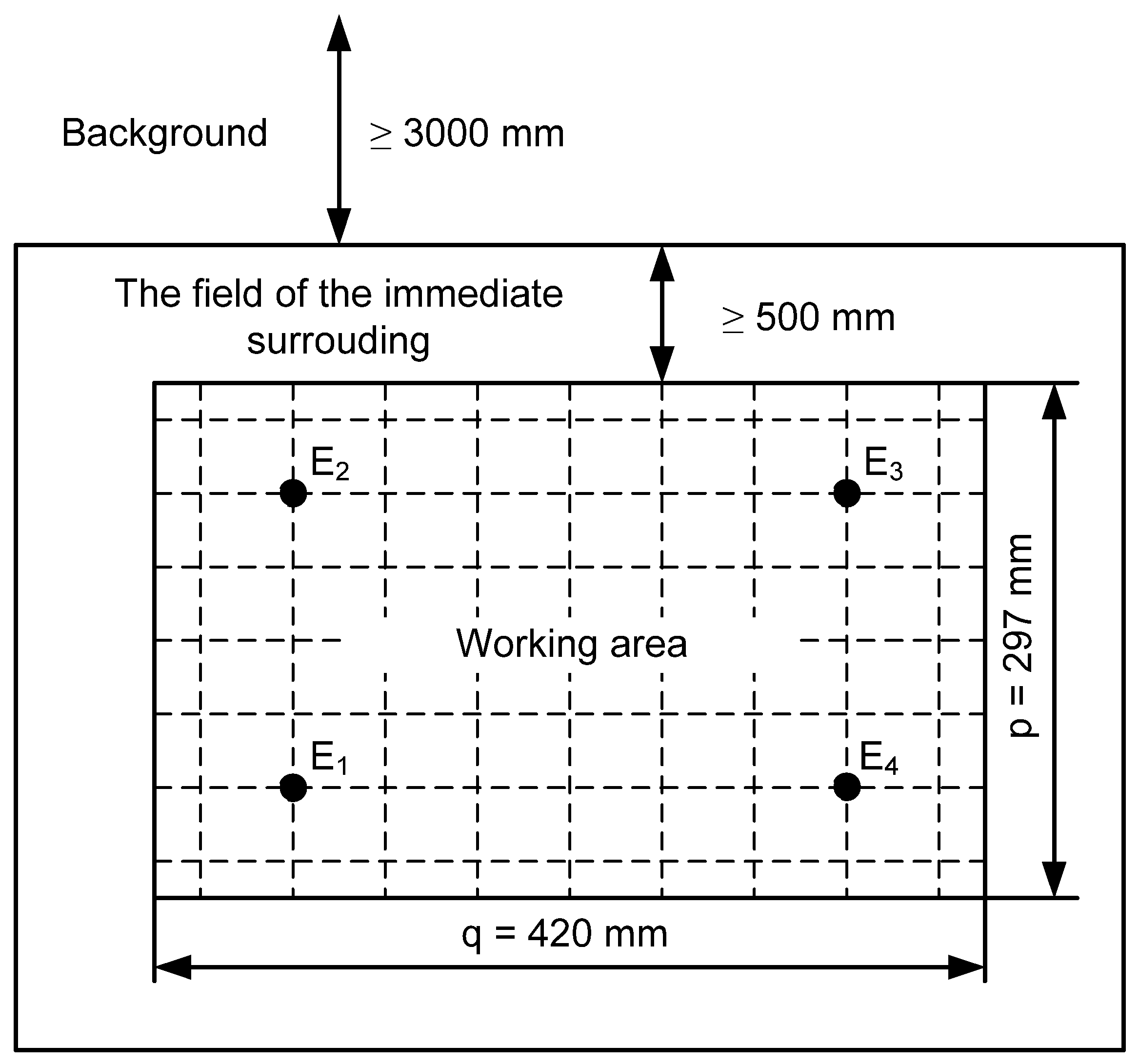
Based on the standards, a working area of A3 size (297 × 420 mm) is defined. The standards define this area—the field of the task as the space in which the visual task is performed. The surroundings of this space are called the field of the immediate surroundings. That is, the space within the field of view in the shape of a belt around the task field adjacent to it, and at least 0.5 m wide. And then the background—the area within the field of view that is located adjacent to the immediate surrounding field. The background must not contain any task field or any field of immediate vicinity, and its width is defined as at least 3 m. Figure 1 shows the dimensions of the working area and the location of the used illuminance sensors.
The controlled parameter characterizing the quality of lighting at the workplace is the illuminance [48]. Assuming that the light source is punctual, a simplified formula can be used for illuminance at point P of the plane under consideration [48] of the form
where I is the luminous intensity in the P direction, r is the distance of the light source to the point P, α is the angle of incidence of the light, and h is the distance of the light source from the plane under consideration.
In order to measure the value of the illuminance on the surface, the average illuminance should be determined. In practice, it is used to calculate the average value of illuminance from the average illuminance for a representative number of measurement points n in a given area [48].
The analyzed norms indicate only the limit values that cannot be exceeded. Therefore, in our work we use not only average values, but also extreme values, e.g., minimum illuminance, which is the lowest value of illuminance in one of selected points in a working area. The standard [1] requires that minimum values of the average illuminance should be maintained, depending on the type of visual work performed and the type of room. The normative minimum permissible average illuminance values range from 10 lx for general orientation in an illuminated room to 1 klx for prolonged and strenuous visual work.
The standard defines also the operational illuminance , from which the value of the average illuminance in the working area cannot be lower. The permissible value of the operational illuminance depends on the activity performed. For example, for activities related to the precise assembly of measuring instruments, the value of operational illuminance is 1 klx, while for the assembly of mobile devices, this value is only 750 lx [1].
In the considerations presented in this paper, the value of the uniformity of illumination δ was also used, determined by the ratio of minimum illuminance Emin to the average illuminance on surface . The standards define the lowest allowable value of δ on a given surface, according to the type of performed activities and for the immediate surroundings containing the working area. For the working area in which continuous workshop work is performed, the value of the minimum permissible value of δ is 0.65, while for occasional work, this value is only 0.4. The permissible value of δ for the working area cannot be lower than 0.7, while the value of this parameter for the area of the immediate surroundings cannot be lower than 0.5 [1].
Measurements of illuminance should be made on the rectangular working area of the dimensions equal to p and q. When interpreting the results of general lighting measurements, one should take into account the recommendation that in the place of permanent residence, the operational illuminance should not be lower than 200 lx [1].
An important parameter characterizing the illumination of the area under consideration is the smallest permissible number of measurement points on an evenly lit working area. It depends on the parameter w given by the formula:
If the value of the parameter w < 1, then it is required to measure the illuminance at 4 points, for 1 < w < 2—at 9 points, for 2 < w < 3—at 16 points, and for w > 3—at 25 points [44].
In order to determine the uniformity of the illuminance distribution δ for the working area, the quotient of the minimum illuminance Emin and the average illuminance Eav in the selected working area should be determined. The lowest value of δ cannot be lower than 0.65 for the working area in which continuous work is performed, or 0.4 for the working area in which casual work is performed.
Apart from the number of measuring points, the distances between these points are also determined. The requirements vary depending on whether the measurement is for the working area, the field of the immediate surroundings, or the background. The standard [50] recommends the use of a measurement grid with meshes in the form of rectanglers, preferably squares. The ratio of the length to the width of such a rectangle should be in the range of 0.5 to 2. The maximum distance between the measurement points x is determined using the formula [48]:
According to the standard [50], the value of x should not exceed 10 m for outdoor applications. Knowing the maximum distance between measurement points x and the length of the longer side q, it is possible to determine the minimum number of measurement points N on this side. It is an integer that is closest to the result of dividing the length of the longer side q by the distance between the measurement points x.
Based on the dependence (3), the standard [42] shows the relationship between the value of the uniformity of the illuminance of the working area, the maximum distance between the measurement points x, and the minimum number of these points N, which are presented in Table 1.
Following the above-mentioned principles, the design adopted the working area as an area of A3 size (297 × 420 mm), and thus, 4 was a sufficient number of measurement points. However, during the research, 63 regularly placed measurement points were used to plot the lighting intensity distribution. The arrangement of the illuminance sensors is shown in Figure 1.
3. Investigated Lighting Control System
Figure 2 shows the block diagram of an embedded system for controlling the lighting of an office station, the main component of which is a control system built using the STM32L475VGT6 processor (ST Microelectronics, Budapest, Hungary) [49]. This processor is a component of the Discovery B-L475E-IOT01A2 evaluation board adapted to work with IoT (Internet of Things) via the Wi-Fi module. This system uses an analog-to-digital converter to record the voltages generated by the TEMT6000 (Vishay, Malvern, PA, USA) analog illuminance sensors. In order to generate a PWM signal with a frequency equal to 5 kHz, a timer implemented in the processor is used [51]. The use of such frequency of a PWM signal allows eliminating the phenomenon of LED flickering, which can be observed at low frequency values (below 100 Hz) of this signal.
In order to galvanically separate the ground circuit of the evaluation board and the LED power supply, an optocoupler CNY17-4 (Vishay, Malvern, PA, USA) is used [52]. If the optoisolator is not used, very high RMS (Root Mean Square) values of noise at the output of the TEMT6000 illumination sensor, exceeding 50 mV, are observed, making the operation of the control algorithm impossible. In order to increase the current efficiency of the PWM signal output, the MCP1405 (Microchip, Chandler, AZ, USA) controller [53] is used. A MOSFET of the IRF540 (Vishay, Malvern, PA, USA) type is used as a device switching the LED current [42].
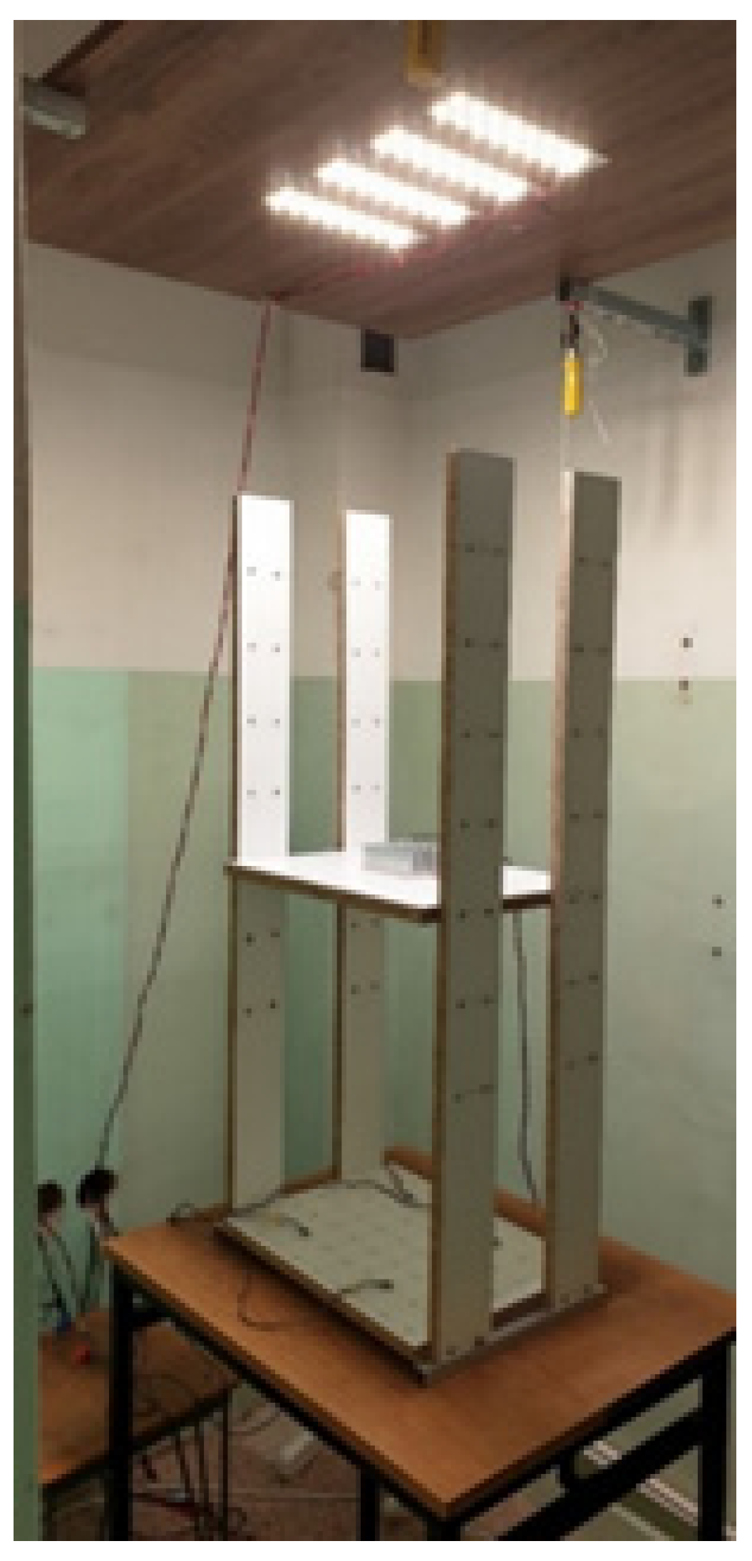
Another important task is to ensure appropriate measurement conditions. To achieve this, a test set-up is prepared to ensure stable conditions of external lighting that would enable tests to be carried out on the control system. One such condition is to ensure the possibility of changing the intensity of external lighting, which would allow the control system response to be tested. An additional advantage of the test set-up is an easy and precise change in the position of the light intensity sensors in order to investigate the distribution of the illuminance generated by the point light sources used.
The prototype test set-up presented in Figure 3 met all the established goals. Placing the set-up in a darkroom helped provide a stable environment that allowed for precise measurements of the control system.
A plate is placed at the bottom of the test set-up with 63 regularly distributed points for the placement of sensors, which allows for an easy change in the position of the sensors. The position of the sensors could be changed within the accepted working area of the dimensions of 297 × 420 mm, in 7 rows and 9 columns. The measuring surface prepared in such a way ensures that the sensors are precisely positioned each time, which allows obtaining reliable results and measurement of illumination intensity distribution. As mentioned earlier, 4 positions are selected in which sensors E1, E2, E3 and E4 are placed, as shown in Figure 1. During the investigations, the height at which the point light source controlled by the system is fixed is 50 cm.
In the presented set-up, an analog sensor is used to measure the light intensity, which is sensitive to the visible light, with the half sensitivity angle ϕ = ±60°. The photosensitive element of the optical sensor is a phototransistor. Its operating parameters are presented in Table 2.
This sensor is mounted on a PCB (Printed Circuit Board) of the dimensions of 11 × 11 mm using the SMD (Surface Mounted Devices) technology. As a result, its pins are soldered to pads (2.54 mm raster), allowing for connection to the breadboard or the main module in the form of the STM32Disco development board used in the presented system, or the Arduino development kit. The TEMT6000 optical sensor system has three GND pins—system ground, VCC—5 V supply voltage and VOUT—analog output.
The sensor TEMT6000 [54] is characterized by a narrow range of the measured illuminance values, which typically do not exceed several klx. It is caused by the properties of the phototransistor acting as a photosensitive element. Such sensors are characterized by quick saturation of the phototransistor’s output characteristic. The TEMT6000 sensor contains, apart from the phototransistor, a 10 kΩ resistor limiting the collector current. The voltage drop across this resistor is fed to the input of the analog-to-digital converter of the measuring system, which is presented in [7].
The applied illuminance sensors E1–E4 of the TEMT 6000 type are the main components of the feedback loop of the control system used to adjust the illuminance of the point light source. These sensors also respond to a change in the intensity of external lighting. The use of this type of sensors was determined by the low values of the measured illuminance, which—in the system under consideration—did not exceed 1 klx.
During the tests, the LED of the type XMLBWT-00-0000-000LT40E4 (Cree LED, Durham, NC, USA) served as a point light source, which is a part of the system during the calibration of sensors and the measurement of its static and dynamic parameters. The applied LED can work when the maximum forward current IFmax = 3 A, the total power Ptot is up to 10 W, the emitted luminous flux reaches 341 lm at forward current IF = 0.35 A, while the emission angle is 125°. While the lighting system operates, the LED is mounted on a RAD-A5723/100 heat sink. The Ring XRE module is also tested as a point source of light, which contains six diodes of the XRE-L1-0000-006F8 (Cree LED, Durham, NC, USA) type [55] connected in series with the maximum forward current IFmax = 0.7 A, which is used for investigations of the dynamics of the system. Figure 4a shows a view of LED light sources in the form of an XML2 diode [43], while Figure 4b shows the Ring XRE module.
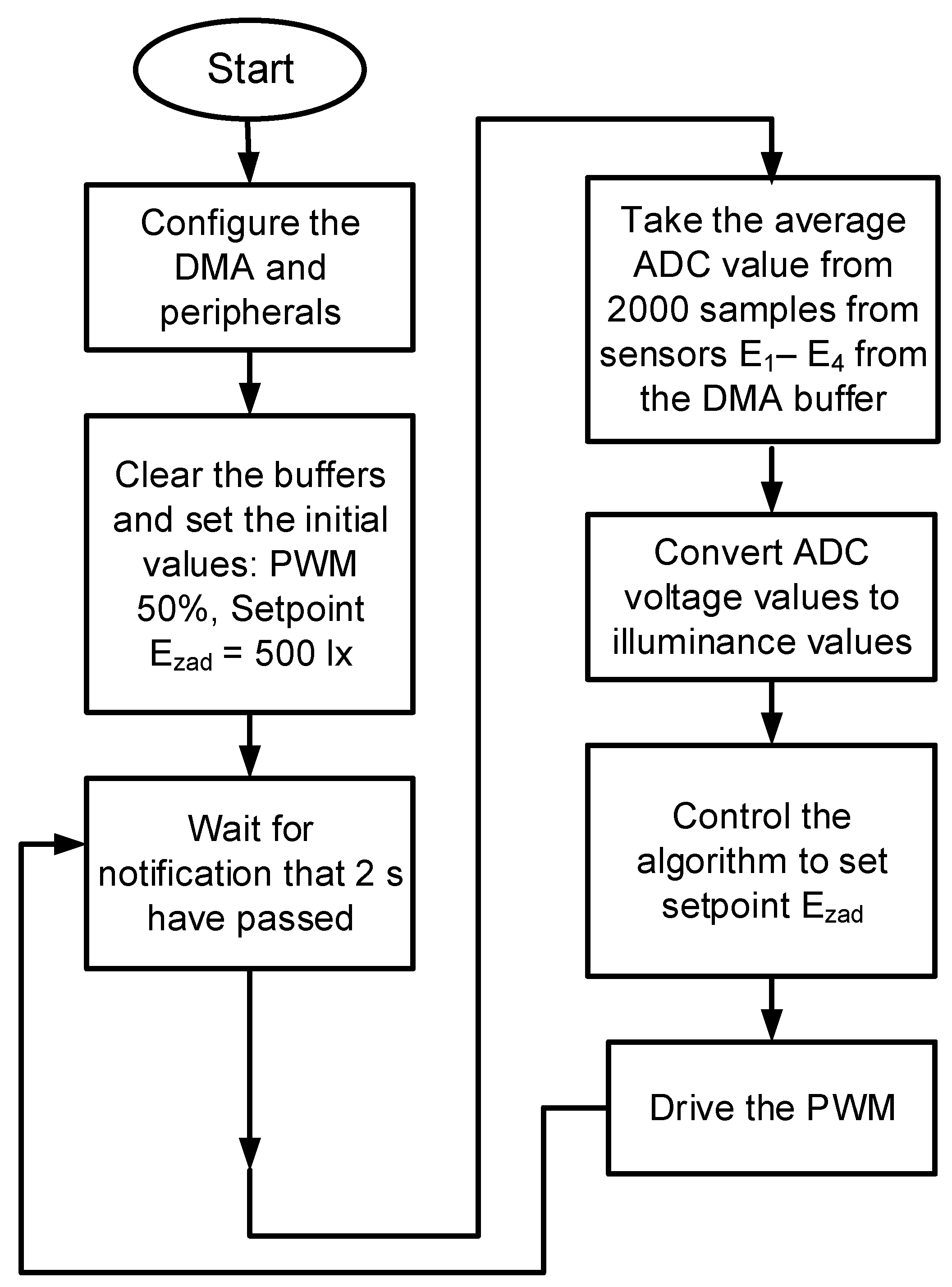
In order to control the lighting of the office station, an algorithm implemented in the STM32L4 microcontroller is prepared. The analog-to-digital converter ADC takes the data from four analog sensors of illuminance. The next step is to average the measurement results of these sensors. The transmitter takes 2000 samples from each optical sensor and averages the measurement results. The averaging operation for four sensors takes no longer than 5 s. The next step is to compare the measured value of illuminance with the value adopted as the reference value. If these values are equal, the next 2000 samples are read, while the reading is overstated or lowered in relation to the adopted standard, the average value of the LED current is adjusted using the duty cycle of the signal controlling the gate of the MOSFET.
Figure 5 shows the algorithm of the main part of the firmware. It does not contain the work of the DMA (Direct Memory Access) system, which, without using the processor’s time, copies the readings from the analog sensors on an ongoing basis and places them in the buffer. From it, they are taken every 1 ms and averaged to get rid of the noise related to the quality of the sensors. The algorithm below does not include communication with the PC application. At any time, the user, after connecting a computer with the STM32Disco evaluation kit (ST Microelectronics, Budapest, Hungary) via the USB (Universal Serial Bus) port, can download the current data from the system and send new set values. This does not stop the program; the new data are updated, and the next time the loop is run.
The control algorithm plays a key role in the operation of the system, therefore its selection was not unambiguous. Finally, a very simple iterative algorithm presented in Figure 6 is selected.
The algorithm also uses the calculated value of illuminance in the working area and compares it with the set value. It takes into account a possible error of 20 lx. If the calculated value, taking into account the error value, is different than the set value of illuminance, a correction is made, i.e., a change in the PWM signal fill value, in order to change the value of illuminance. In the case where the calculated value is lower than the set value, the algorithm increases the duty cycle of the PWM signal by the correction value, and in the case where the calculated value is higher than the set value, the correction consists of reducing the duty cycle of the PWM signal by the correction value. During the tests, the correction value was set at 2%, which is sufficient for the control system to be considered accurate, and at the same time, the control can be considered fast enough.
Although the characteristics of the algorithm used do not ensure a constant system response time (it increases with an increase in the difference between the value obtained from the sensors and the set value), the algorithm can be considered sufficient, as proved by the tests presented later in the paper. The value mentioned earlier as the error value is entered into the algorithm to ensure the stability of the circuit. It is not desirable that the illuminance should constantly change in the pursuit of perfection. The sensors are not accurate enough to ensure a constant reading of the values, and the ambient lighting conditions may change slightly. If the system fails to maintain the ideal settings in this situation, it could cause flickering of light, which leads to eye fatigue for the user staying in such conditions. This value introduces a permitted error that is not corrected, but ensures the stability of the control system and at the same time ensures its sufficient quality.
To ensure higher accuracy and a more stable system response time, it was possible to use an algorithm of higher complexity, which would not merely compare the actual value to the set value on a larger/smaller basis. The algorithm could calculate the difference between these values and, depending on its magnitude, change the duty cycle of the PWM signal by a higher or lower value.
The advantage of this solution would be to increase the speed of the system reaction time and a more stable operation of the system. The system would have to calculate by what fill value it should change the settings to obtain the set point. It was possible to use artificial intelligence algorithms for this purpose, which would have meant following the trends in the technology industry. Such a solution would have been faster, but the advantage of the solution used was that the change in settings was very smooth, thereby having a positive impact on the user’s eyesight. Additionally, during the tests, the iterative algorithm presented above turned out to be sufficient, fulfilling all the requirements. The introduction of a more elaborate algorithm could mean greater complexity of the program, which could make it more unreliable, and also, if the project is to be transferred to a device to be sold on the market, it could make it impossible to optimize the hardware, mainly the processor. More complex algorithms require processors with more computing power and memory. The used algorithm makes it possible to optimize costs and reduce electricity consumption.
The use of artificial intelligence or machine-learning algorithms would also increase the required microcontroller cache memory, which would lead to greater complexity of the control system, the need to use a more complex microcontroller architecture, and disprove the assumption, thereby increasing the cost of the entire system. Such a solution would also lead to the consumption of more electricity, which would disprove the assumption of saving energy consumed by the proposed lighting control system in the workplace.
In the papers [8,9,10,11,12,13], systems using artificial intelligence and machine-learning algorithms are proposed. However, the authors of these systems mention considerable computational effort required for the stable control of the solid-state light source, and the complexity of systems for continuous measurement of the illuminance. It leads to a need for microcontroller systems that additionally requires digital signal processing algorithms. These systems also show long operating times, exceeding even several seconds. The discussed papers also present the solutions that make use of programmable circuits, which enable the implementation of a control system, additional amounts of cache memory, and digital signal processing circuits in one integrated circuit, which significantly limits the profitability of such a project.
The advantage of the control system proposed in this paper lies in the optimization of the costs incurred, because the control system uses a very popular and cheap microcontroller from the STM32L4 family, ensuring low power consumption, which leads to savings in electricity consumption. This system, in comparison with the literature systems, is also characterized by the simplicity of the control algorithm because it uses only one feedback loop for four measurement sensors, while the literature systems use separate feedback loops for each used illuminance sensor.
4. Investigation Results
In order to verify the correct operation of the presented system, many static and dynamic tests were carried out on the previously presented test set-up. Illuminance distributions were determined for the light sources in the form of a single XML2 power LED and the LED Ring XRE module at different illuminations. Values of illuminance were previously determined by measurements with the L200 luxmeter manufactured by Sonopan [56] used as the reference device. The actual values of illuminance at points E1–E4 were measured using sensors TEMT6000. A detailed diagram of the location of these sensors is shown in Figure 1. By analyzing the data from TEMT6000 sensors, it was possible to determine the value of the average illuminance Eav and the minimum value of the illuminance Emin for the working area.
Section 4.1 presents the measurement results obtained with the open feedback loop, and Section 4.2 with the closed feedback loop.
4.1. Investigations of the System with the Open Feedback Loop
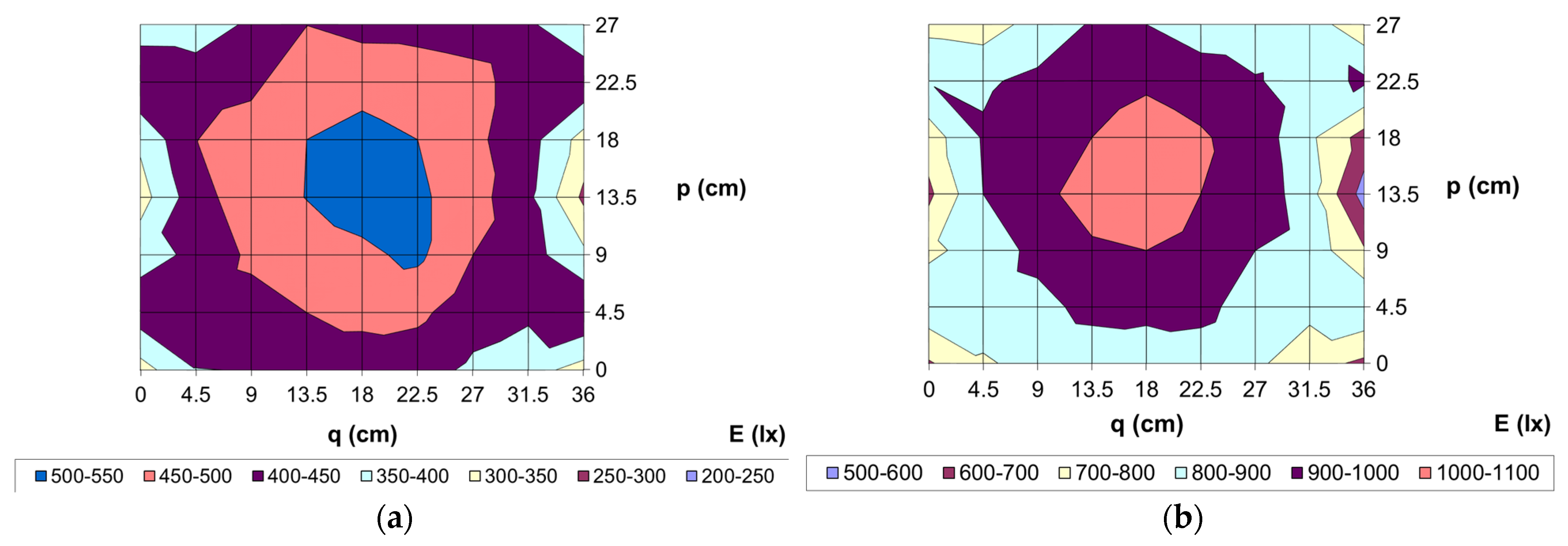
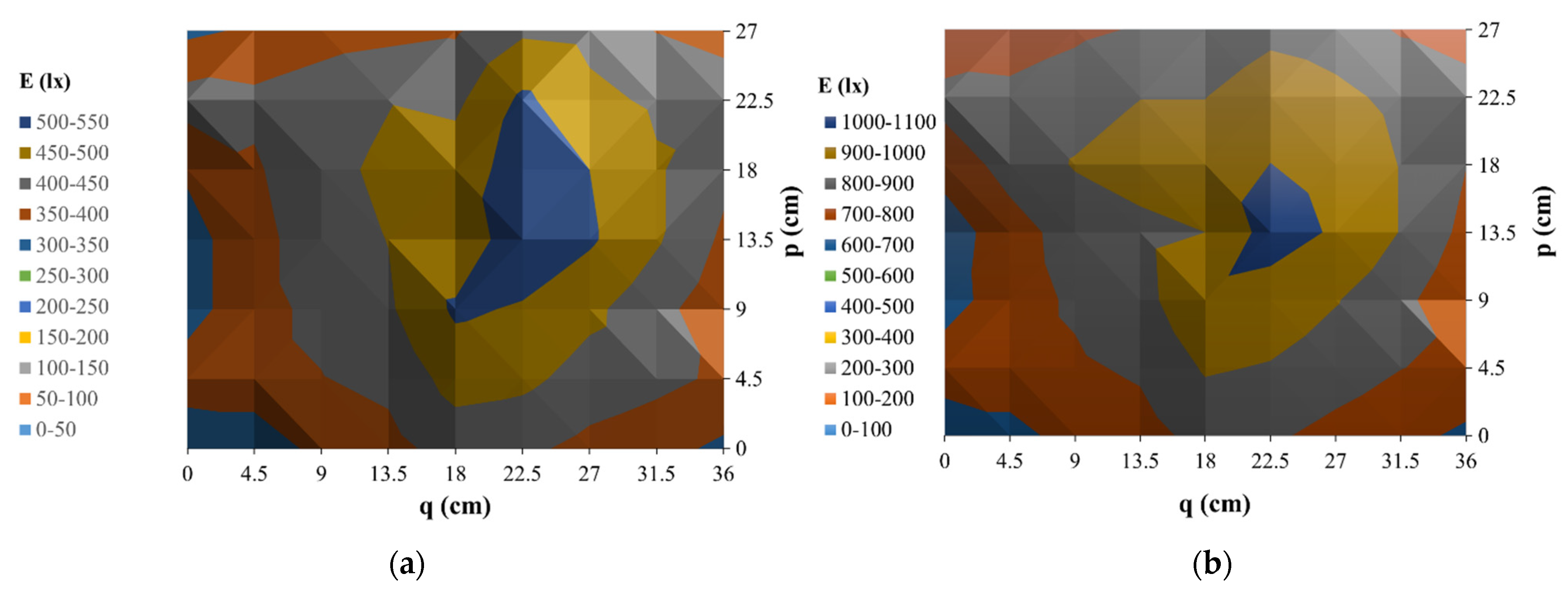
Figure 7 shows the measured illuminance distribution for two different LED forward current values of 0.804 A (Figure 7a) and 1.875 A (Figure 7b), respectively. As can be seen, the higher value of the uniformity of the illumination distribution δ, equal to 0.673, is obtained for the LED forward current equal to 0.804 A. With the forward current equal to 1.875 A, the uniformity δ is equal to 0.642.
As can be seen, in the vast majority of the illuminated area, the differences between the measured values of illuminance do not exceed 20%. Only at the edges of the area under consideration, lower values of the measured quantity are observed. On the basis of the presented measurement results, the values of parameters characterizing the lighting of the considered working area were determined. For the distribution shown in Figure 7b, the value of the parameter Eav = 869.7 lx, Emin = 558 lx, and δ = 0.642. In turn, for the distribution from Figure 7a, the values of these parameters are 429.2 lx, 289 lx and 0.673, respectively. As can be seen, higher uniformity was obtained for the LED forward current of 0.804 A.
Figure 8 shows the measured illuminance distributions of the LED Ring XRE module, with the forward current value varying from 0.25 A to 0.66 A. Comparing the uniformity of illuminance for both point light sources, it can be concluded that the XRE module achieves better uniformity illuminance, which at the forward current equal to 0.25 A was δ = 0.752.
It can be seen that the measured illuminance distributions are more uniform, and thus this module illuminates the working area more evenly than the XML2 power LED. The obtained values of δ exceeded 0.7 determined by the standard. The most uniform illuminance (δ = 0.778) was obtained for the Ezad equal to 750 lx measured with a Sonopan L-200 luxmeter (Sonopan, Białystok, Poland), and forward current equal to 0.42 A. The Ring XRE module was least uniformly (δ = 0.752) illuminating the working area for the forward current of the module equal to 0.66 A, and the extreme values in this case were Emax = 1040 lx and Emin = 633 lx. However, in the case of the distribution for the value of Ezad equal to 500 lx, the extreme illuminance values were Emax = 536 lx, Emin = 314 lx. Each of the uniformity values obtained with the use of the Ring XRE module is compliant with the standard [13], because it exceeds 0.7.
In the paper [57], experimental studies were carried out on the measurements of light distribution characteristics by several arbitrarily selected solid-state light sources. A strong influence of the forward current can be noticed in the distribution characteristics of point light sources such as power LEDs. The shape of these characteristics is also influenced by the optical axis, in which the Spatial Radiation Patterns were measured.
In this paper, two different types of XML2 (Cree LED, Durham, NC, USA) and XRE LEDs (Cree LED, Durham, NC, USA) are used. It should be noted that these LEDs have different dimensions, and they also have Lambertian lenses of different dimensions.
In the paper [4], imperfections occurring in the optical systems of solid-state light sources, which also affect the uneven distribution of emitted light intensity, are mentioned as having a big impact on the obtained luminous flux. These imperfections are manifested by the contamination of optical systems and microcracks that are not visible, but have a large impact on the obtained photometric solid.
4.2. Investigations of the System with the Closed Feedback Loop
Table 3 shows the measured and calculated values of electrical and optical parameters for both point light sources while determining the lighting intensity distributions, the graphs of which are shown in Figure 7 and Figure 8.
Figure 9 shows the view of the measurement set-up. Its components are the GW INSTEK oscilloscope of the GDS2104A (GW INSTEK, New Taipei, Taiwan) type [58], which was used to record voltage and current waveforms with the use of voltage probes and the TCPA300 (Tektronix, Beaverton, USA) current probe [59] by Tektronix.
The performed tests of dynamic parameters concerned the waveforms of voltage VGS between the gate and the source of the IRF540 transistor, the drain current ID of this transistor and voltage VOUT at the output of the TEMT6000 sensor. The tests were performed for both the considered point light sources. The values of external illumination Ezew and the set point illumination Ezad of the light source were regulated. The outdoor lighting module of the prototype stand was built using four LED modules connected in parallel, type XPGBWT-H1-CCKP-AFHE5KE40 (Cree LED, Durham, NC, USA) [60]. Each of these LED modules contains 16 series-connected LEDs, and is mounted on a common MCPCB (Metal Core Printed Circuit Board) substrate with dimensions of 22.2 × 5 cm. These modules were built by Fideltronik Poland in Sucha Beskidzka, Poland [61], and will hereinafter be referred to as AGH modules. By using two resistors of the values of R4 = 10 Ω and R5 = 20 Ω, respectively, it was possible to stepwise adjust the value of external lighting intensity Ezew with the values of 200 lx and 100 lx, respectively. By turning off the power supply, the value of external illumination Ezew equal to 0 can be also obtained.
Figure 10 shows a diagram and the dimensions of the external lighting source.
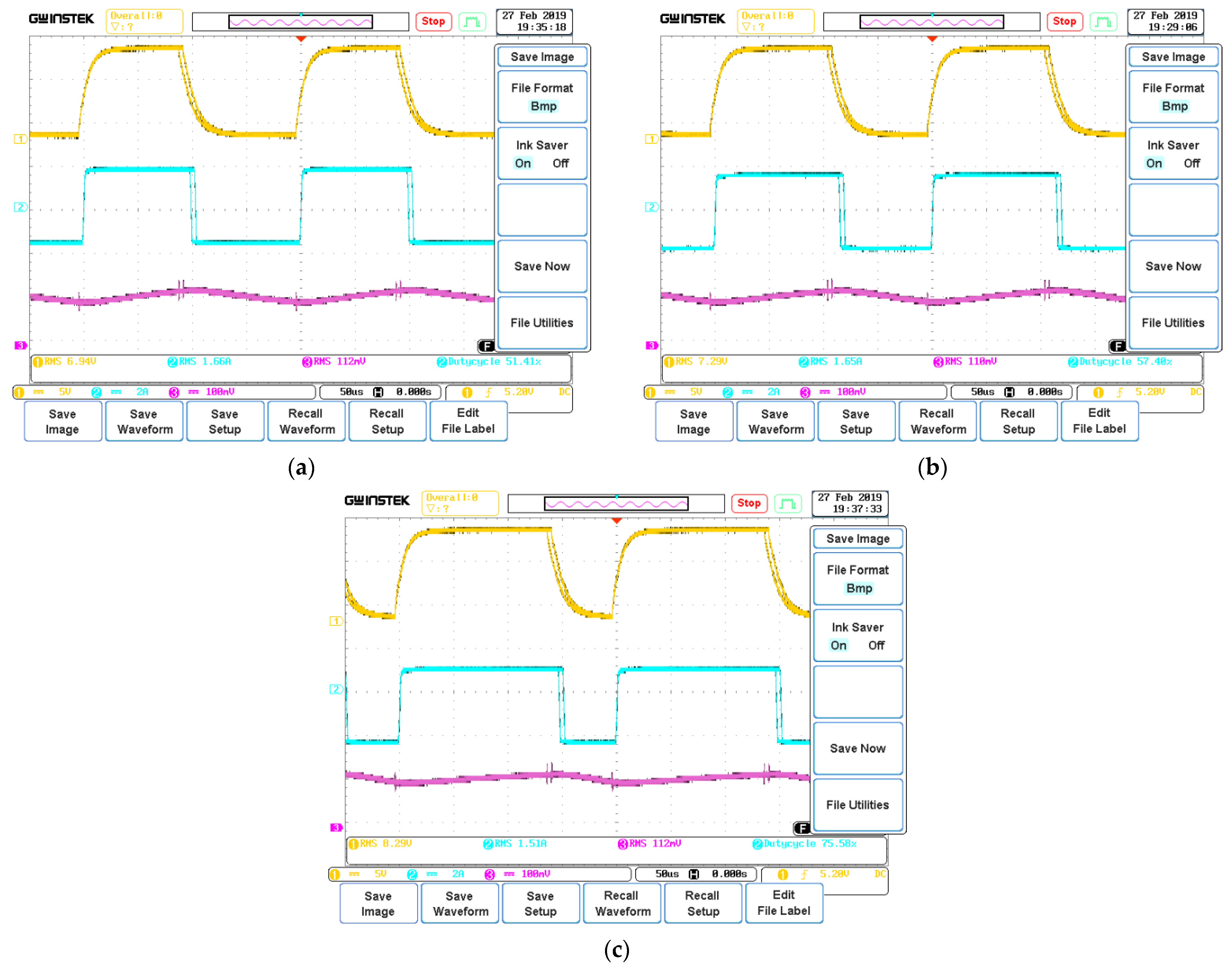
Figure 11 shows the measured waveforms of VGS voltage of the transistor (yellow), VOUT voltage at the output of the TEMT6000 sensor (pink), and the drain current ID of the transistor (blue) for the applied spotlight source—XML diodes-B2, respectively, for the value of external illuminance Ezew equal to 200 lx (Figure 11a), 100 lx (Figure 11b) and 0 (Figure 11c), respectively. The waveform of the drain current is close to a square wave with the duty cycle d, which depends on the gate control level of the transistor used in the prototype circuit. By analyzing the following waveforms and the values collected in Table 4, it can be seen that with an increase in the intensity of external lighting, the duty cycle d decreases, and the RMS value of the current on the point light source decreases. On the other hand, the RMS value of the voltage at the photodetector changes very little.
Figure 12 shows voltage and current waveforms in the system with the Ring XRE module, with the set point source illuminance Ezad = 750 lx and external illuminance Ezew equal to 200 lx (a) or 100 lx (b), respectively. The convention for determining the appropriate waveforms is the same as in Figure 11.
In this case, the system behaves in the same way as the system with the XML2 power LED. The increase in external illuminance is the same as the decrease in the value of the duty cycle d of the control signal, and the decrease in the RMS value of the current flowing through the Ring XRE module. On the other hand, the RMS value of the voltage on the photodetector changes only insignificantly. The values of the obtained electrical and optical parameters of the tested system are presented in Table 5.
When analyzing the operation of the control system for different setpoints of illuminance Ezad for both point light sources, it can be seen that the control system for lower values of Ezad is characterized by higher accuracy of the settings. It is demonstrated by the obtained higher difference in the duty cycle of the control signal for the same change in value of external illuminance.
Comparing the two tested point light sources, it can be concluded that in the case of the Ring XRE module we obtain a lower forward current value than in the case of the XML2 power LED, for which we need a slightly higher value of the duty cycle of the control signal in order to obtain the same value of illuminance at the identical external Ezew.
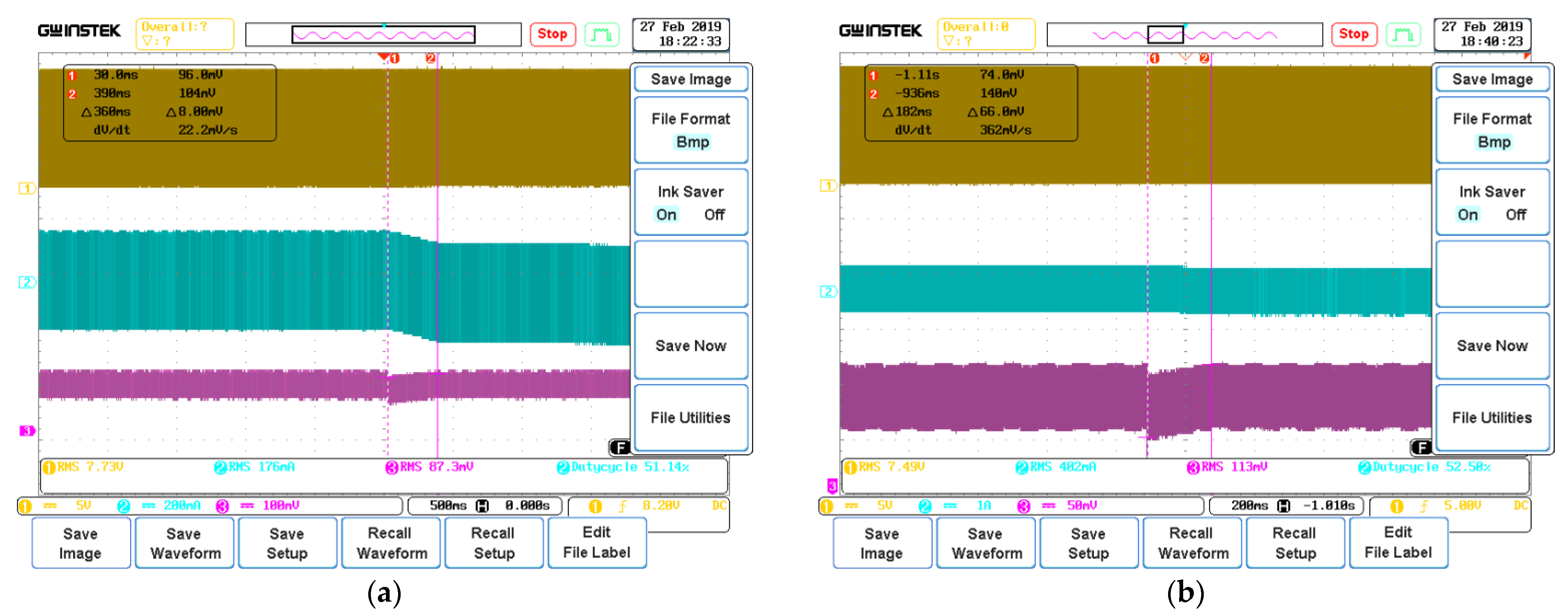
Its dynamics plays an important role in the control system, and more precisely, the speed of the algorithm, i.e., the time in which the system returns to the set value after changing the external lighting intensity. Two test cases were performed for the Ring XRE module. In the first case, the set value of illuminance Ezad of the control system was 500 lx. The external lighting at the initial moment assumed the value equal to 200 lx. During the test, the series resistance value was switched from 10 Ω to 20 Ω, which resulted in a change in the value of external illuminance Ezew. The system adaptation time to such a change was 0.36 s, which is illustrated by the waveforms presented in Figure 13a.
Another test case covered the same change in external illuminance, but the set value in the system was different at 750 lx. The algorithm’s operating time was 0.182 s, and the waveforms for this case are shown in Figure 13b.
Next, the tests were performed using the XML-B2 LED as a point light source. Three test cases were performed for a change in external illuminance from 200 lx to 100 lx at Ezad = 500 lx, from 200 lx to 100 lx at Ezad = 750 lx, and from 200 lx to 0 at Ezad = 750 lx.
Upon analyzing Table 6, it can be seen that the bigger the difference in the duty cycle between the two states, the longer the adaptation time of the control system. This is the result of the aforementioned drawback of iterative algorithms. However, as one can see, none of the times exceed even one second, so it can be considered almost imperceptible, and at the same time the change is smooth and does not cause light flickering.
When analyzing the results of calculations of the electrical power consumed by a point light source presented in Table 4 (XML2) and in Table 5 (Ring XRE), it can be noticed that along with an increase in the value of the illumination of external AGH LED panels (Figure 10), the power consumed by point light sources decreases. This decrease in power affects both point light sources. The observed decrease in the electrical power consumption results in long-term energy savings due to the use of the control system proposed by the authors.
5. Conclusions
The paper presents an embedded system for automatic control of lighting in an office station with a point light source and a control system having a microcontroller with ARM (Advanced Risc Machine) architecture. By carrying out experimental research on the prototype system, it was proved that it works according to the assumptions previously made.
The correct operation of the system means maintaining the set value of illuminance by automatically regulating the current supplying the point light source. The user can control the set value of illuminance, and the system is able to maintain each of the values quoted in the above mentioned standards. The uniformity that meets the requirements of the standards was not achieved with the XML-B2 LED. The uniformity δ = 0.673 for the working area was characterized, which does not exceed the threshold of 0.7 while the use of the Ring XRE module ensured the uniformity value compliant with the standards.
It was proved that the system works stably, and there is no flickering of lighting or other inconveniences related to inadequate lighting of the working area. This was achieved thanks to sufficient control accuracy and appropriate selection of the algorithm.
Such solutions allow the reduction of costs and are user-friendly. Due to system flexibility, it offers the possibility of developing the project, extending it with further possibilities and applications, or using more complex solutions such as the aforementioned development board adapted to IoT. This would enable calculations in the cloud or remote viewing and the setting changes. This could have many advantages in spacious workplaces or for people with reduced mobility. In such a case, the system could be extended with new functionalities, such as controlling a larger number of lighting points that could cooperate with each other, or calculating power consumption and related costs.
Author Contributions
Conceptualization, K.G. and P.P.; methodology, P.P.; software, S.W.; validation, P.P. and S.W.; investigation, P.P. and S.W.; writing—original draft preparation, K.G., P.P. and S.W.; writing—review and editing, P.P. and K.G.; visualization, P.P. and S.W.; supervision, K.G.; funding acquisition, K.G. All authors have read and agreed to the published version of the manuscript.
Funding
This research was funded by the program of the Ministry of Science and Higher Education called “Regionalna Inicjatywa Doskonałości” in the years 2019–2022, project number 006/RID/2018/19, sum of financing 11,870,000 PLN.
Institutional Review Board Statement
Not applicable.
Informed Consent Statement
Not applicable.
Data Availability Statement
Not applicable.
Conflicts of Interest
The authors declare no conflict of interest.
References
- PN-EN 12464-1:2022-01; Light and Lighting. Lighting of Workplaces, Part 1: Interior Workplaces. Official Journal of the European Union: Luxembourg, 2015.
- Schubert, E.F. Light Emitting Diodes, 3rd ed.; Rensselaer Polytechnic Institute: Troy, NY, USA, 2018. [Google Scholar]
- Lasance, C.J.M.; Poppe, A. Thermal Management for LED Applications; Springer: Dordrecht, The Netherlands, 2014. [Google Scholar]
- Smith, W.J. Modern Optical Engineering: The Design of Optical Systems, 4th ed.; McGraw Hill: New York, NY, USA, 2008. [Google Scholar]
- Górecki, K.; Ptak, P. Modelling LED lamps with thermal phenomena taken into account. Microelectron. Reliab. 2017, 79, 440–447. [Google Scholar] [CrossRef]
- Winder, S. Power Supplies for LED Driving, 2nd ed.; Elsevier BV: Aalborg, Denmark, 2017. [Google Scholar]
- Ptak, P.; Górecki, K.; Wnuczko, S. Embedded system to control lighting of the office workplace. Przegląd Elektrotechniczny 2018, 94, 76–79. [Google Scholar]
- Afshari, S.; Mishra, S. A Plug-and-Play realization of decentralized feedback control for smart lighting systems. IEEE Trans. Control Syst. Technol. 2016, 24, 1317–1327. [Google Scholar] [CrossRef]
- Chew, I.; Kalavally, V.; Pin Tan, C.; Parkkinen, J. A Spectrally tunable smart LED lighting system with closed-loop control. IEEE Sens. J. 2016, 16, 4452–4459. [Google Scholar] [CrossRef]
- Fleck, J.L.; Cassandras, C.G.; Geng, Y. Adaptive quasi-dynamic traffic light control. IEEE Trans. Control Syst. Technol. 2016, 24, 830–842. [Google Scholar] [CrossRef]
- Nam, T.P.; Van Doai, N. Application of inteligent lighting control for street lighting system. In Proceedings of the International Conference on System Science and Engineering (ICSSE), Dong Hoi, Vietnam, 20–21 July 2019; pp. 53–56. [Google Scholar]
- Hsia, S.C.; Sheu, M.H.; Ciou, J.J. Cost-effective LED dimming driver with single chip design for smart lighting system. IEEE Access 2020, 8, 141025–141032. [Google Scholar] [CrossRef]
- Boscarino, G.; Moallem, M. Daylighting control and simulation for LED-based energy-efficient lighting systems. IEEE Trans. Ind. Inform. 2016, 12, 301–309. [Google Scholar] [CrossRef]
- Pandharipande, A.; Caicedo, D.; Wang, X. Sensor-driven wireless lighting control: System solutions and services for intelligent buildings. IEEE Sens. J. 2014, 14, 4207–4215. [Google Scholar] [CrossRef]
- Apostolidou, N.; Valsamas, F.; Baros, D.; Loupis, M.; Dasteridis, V.; Kokkinis, C. Innovative Energy-recovery unit for the LED-lighting system of heavy-duty vehicles. Clean Technol. 2021, 3, 581–593. [Google Scholar] [CrossRef]
- Qin, L.; Pena-Garcia, A.; Leon, A.S.; Yu, J.C. Comparative study of Energy savings for various control strategies in the tunel lighting system. Appl. Sci. 2021, 11, 6372. [Google Scholar] [CrossRef]
- Plorer, D.; Hammes, S.; Hauer, M.; Van Karsbergen, V.; Pfluger, R. Control strategies for daylight and artificial lighting in office buildings-a bibliometrically assisted review. Energies 2021, 14, 3852. [Google Scholar] [CrossRef]
- Haus, J. Optical Sensors. Basics and Applications; Wiley-VCH Verlag: Veinheim, Germany, 2010. [Google Scholar]
- Ptak, P.; Górecki, K.; Gensikowski, M. Comparison of dynamic properties of the selected photometric sensors. Przegląd Elektrotechniczny 2020, 96, 110–114. [Google Scholar]
- Deng-feng, L.; Yun-ting, B.; He, W.; Hu, L. Design of intelligent lighting control system. In Proceedings of the 2011 IEEE International Conference on Cyber Technology in Automation, Control and Intelligent Systems, Kunming, China, 20–23 March 2011; pp. 134–137. [Google Scholar]
- Chiradeja, P.; Yoomak, S.; Ngaopitakkul, A. Economic analysis of improving the Energy efficiency of nanogrid solar road lighting using adaptive lighting control. IEEE Access 2020, 8, 202623–202638. [Google Scholar] [CrossRef]
- Shahzad, G.; Yang, H.; Ahmad, A.W.; Lee, C. Energy-efficient intelligent street lighting system using traffic-adaptive control. IEEE Sens. J. 2016, 16, 5397–5405. [Google Scholar] [CrossRef]
- Jiang, J.; Mohagheghi, A.; Moallem, M. Energy-efficient supplemental LED lighting control for a proof-of-concept greenhouse system. IEEE Trans. Ind. Electron. 2020, 67, 3033–3042. [Google Scholar] [CrossRef]
- Martirano, L.; Ruvio, A.; Manganelli, M.; Lettina, F.; Venditti, A.; Zori, G. High-efficiency lighting systems with advanced controls. IEEE Trans. Ind. Appl. 2021, 57, 3406–3415. [Google Scholar] [CrossRef]
- Bo, F.; Zhengming, Z.; Yingchao, Z.; Dejia, Z.; Liqiang, Y. Intelligent controller for LEDs lighting systems supplied by batteries. In Proceedings of the IEEE Vehicle Power and Propulsion Conference (VPPC), Harbin, China, 3–5 September 2008. [Google Scholar]
- Mohagheghi, A.; Moallem, M. Intelligent spectrum controlled supplemental lighting for daylight harvesting. IEEE Trans. Ind. Inform. 2021, 17, 3263–3272. [Google Scholar] [CrossRef]
- Pellegrino, A.; Lo Verso, V.R.M.; Blaso, L.; Acquaviva, A.; Patti, E.; Odello, A. Lighting control and monitoring for energy efficiency: A case study focused on the interoperability of building management systems. IEEE Trans. Ind. Appl. 2016, 52, 2627–2637. [Google Scholar] [CrossRef] [Green Version]
- Gao, J.; Luo, J.; Xu, A.; Yu, J. Light intensity intelligent control system research and design based on automobile sun visor of BH1750. In Proceedings of the 29th IEEE Chinese Control And Decision Conference (CCDC), Chongqing, China, 28–30 May 2017. [Google Scholar] [CrossRef]
- Meng-Shiuan, P.; Lun-Wu, Y.; Yen-Ann, C.; Yu-Hsuan, L.; Yu-Chee, T. A WSN-based intelligent light control system considering user activities and profiles. IEEE Sens. J. 2008, 8, 1710–1721. [Google Scholar]
- Wong, C.P.G.; Lee, A.T.L.; Li, K.; Tan, S.C.; Hui, S.Y. Precise luminous flux and color control of dimmable red-green-blue light-emitting diode systems. IEEE Trans. Power Electron. 2022, 37, 588–606. [Google Scholar] [CrossRef]
- Lee, C.T.; Chen, L.B.; Chu, H.M.; Hsieh, C.J.; Liang, W.C. An internet of things (IoT)-based master-slave regionalized intelligent LED-light-controlling system. Appl. Sci. 2022, 12, 420. [Google Scholar] [CrossRef]
- Górecki, P.; Górecki, K. Measurements and computations of internal temperatures of the IGBT and the diode situated in the common case. Electronics 2021, 10, 210. [Google Scholar] [CrossRef]
- Pietruszka, A.; Górecki, P.; Wroński, S.; Illes, B.; Skwarek, A. The influence of soldering profile on the thermal parameters of insulated gate bipolar transistors (IGBTs). Appl. Sci. 2021, 11, 5583. [Google Scholar] [CrossRef]
- Skwarek, A.; Ptak, P.; Górecki, K.; Hurtony, T.; Illes, B. Microstructure influence of SACX0307-TiO2 composite solder joints on thermal properties of power LED assemblies. Materials 2020, 13, 1563. [Google Scholar] [CrossRef]
- Skwarek, A.; Krammer, O.; Hurtony, T.; Ptak, P.; Górecki, K.; Wroński, S.; Straubinger, D.; Witek, K.; Illes, B. Application of ZnO nanoparticles in Sn99Ag0.3Cu0.7-based composite solder alloys. Nanomaterials 2021, 11, 1545. [Google Scholar] [CrossRef]
- Wiśniewski, A. The calculation of energy saving in use light management systems. In Proceedings of the VII Lighting Conference of the Visegrad Countries (Lumen V4), Trebic, Czech, 18–20 September 2018. [Google Scholar]
- Janicki, M.; Torzewicz, T.; Samson, A.; Raszkowski, T.; Napieralski, A. Experimental identification of LED compact thermal model element values. Microelectron. Reliab. 2018, 86, 20–26. [Google Scholar] [CrossRef]
- Górecki, K.; Ptak, P. New dynamic electro-thermo-optical model of power LEDs. Microelectron. Reliab. 2018, 91, 1–7. [Google Scholar] [CrossRef]
- Posobkiewicz, K.; Górecki, K. Influence of selected factors on thermal parameters of the components of forced cooling systems of electronic devices. Electronics 2021, 10, 340. [Google Scholar] [CrossRef]
- Górecki, K.; Ptak, P.; Torzewicz, T.; Janicki, M. Influence of a thermal pad on selected parameters of power LEDs. Energies 2020, 13, 3732. [Google Scholar] [CrossRef]
- Rozporządzenie Ministra Pracy i Polityki Socjalnej z Dnia 26 Września 1997r. w Sprawie Ogólnych Przepisów Bezpieczeństwa i Higieny Pracy. Dz.U. 2003, nr 169, poz. 1650 ze zm. Available online: http://www.przepisy-bhp.abc.com.pl/akt1/-/akt/dz-u-2003-169-1650-t-j--u (accessed on 15 January 2022).
- PN-EN 12464-1: 2011; Light and Lighting. Lighting of Work Places. Part 1: Indoor Work Places. BSI: London, UK, 2011.
- Xlamp XM-L2. Available online: https://cree-led.com/media/documents/XLampXML2.pdf (accessed on 15 January 2022).
- Pawlak, A. Nowe wymagania w projekcie europejskiej normy oświetleniowej. Bezpieczeństwo Pr. 2010, 10, 22–25. [Google Scholar]
- Wymagania Oświetleniowe w Ocenie Ryzyka Zawodowego na Stanowisku Pracy, w: J. Cahrynowicz (red.), Wybrane Kierunki Badań Ergonomicznych w 2009 Roku; Wydawnictwo Polskiego Towarzystwa Ergonomicznego PTErg, Oddział we Wrocławiu: Wrocław, Poland, 2009.
- CIE 17.4:1987; International Lighting Vocabulary. International Commission on Illuminance (CIE): Austria, Vienna, 1964.
- CIE 97.2:2005; Guide on the Maintenance of Indoor Electric Lighting Systems. International Commission on Illuminance (CIE): Austria, Vienna.
- PN-EN 12665:2011; Light and Lighting. Basic Terms and Criteria for Specifying Lighting Requirements. BSI: London, UK, 2011.
- Górecki, K.; Zarębski, J. Pomiary Elementów i Układów Elektronicznych; Akademia Morska w Gdyni: Gdynia, Poland, 2009. [Google Scholar]
- PN-EN 12464-2:2014-05; Light and Lighting. Lighting of Workplaces, Part 2: Outdoor Workplaces. BSI: London, UK, 2014.
- Microcontroller STM32L475VGT6. Available online: http://www.st.com/en/microcontrollers/stm32l475vg.html (accessed on 15 January 2022).
- CNY17-4 Optocoupler Application Note. Available online: https://www.vishay.com/docs/83606/cny17.pdf (accessed on 15 January 2022).
- MCP1405 Gate Driver. Available online: http://ww1.microchip.com/downloads/en/DeviceDoc/22022b.pdf (accessed on 15 January 2022).
- TEMT6000 Light Sensor. Available online: https://www.vishay.com/docs/81579/temt6000.pdf (accessed on 15 January 2022).
- Xlamp X-RE. Available online: https://cree-led.com/media/documents/ds-XRE.pdf (accessed on 15 January 2022).
- Luxmeter L200. Available online: https://www.sonopan.com.pl/pl/produkty/swiatlo/luksomierz-precyzyjny-l-200/ (accessed on 15 January 2022).
- Górecki, K.; Ptak, P.; Bruski, Ł. Spatial radiation patterns of selected solid state light sources. In Proceedings of the 28th International Conference “Mixed Design of Integrated Circuits and Systems”, Łódź, Poland, 24–26 June 2021; pp. 222–227. [Google Scholar]
- Oscilloscope GWInstek GD2104A. Available online: https://www.tme.eu/Document/e0c261d2fc8307355c1e262c24577391/INB-OSC-EN.pdf (accessed on 15 January 2022).
- Current Probe TCPA300. Available online: https://download.tek.com/manual/071118303.pdf (accessed on 15 January 2022).
- Xlamp XPG2. Available online: https://cree-led.com/media/documents/XLampXPG2.pdf (accessed on 15 January 2022).
- Fideltronik Company. Available online: http://fideltronik.com.pl (accessed on 15 January 2022).
Figure 1.
Working area dimensions.

Figure 2.
Block diagram of an embedded system for controlling the lighting of an office station.

Figure 3.
View of the test set-up with external lighting.

Figure 4.
View of the XML2 power LED (a) and the LED Ring XRE module (b).

Figure 5.
Target loop algorithm.

Figure 6.
Control system operation algorithm.

Figure 7.
Distribution of illuminance in the working area for the XML2 power LED and the nominal value Ezad of 500 lx (a) and 1 klx (b).
Figure 7.
Distribution of illuminance in the working area for the XML2 power LED and the nominal value Ezad of 500 lx (a) and 1 klx (b).

Figure 8.
Distribution of the illuminance of the Ring XRE module for the value of Ezad equal to 500 lx (a) and 1 klx (b).
Figure 8.
Distribution of the illuminance of the Ring XRE module for the value of Ezad equal to 500 lx (a) and 1 klx (b).

Figure 9.
View of the measurement set-up.

Figure 10.
Scheme and dimensions of the ceiling modular lighting source.

Figure 11.
Waveforms of voltage VGS, drain current ID, sensor voltage E1 of the system with XML2 power LED at Ezew = 200 lx (a), Ezew = 100 lx (b) and Ezew = 0 (c).
Figure 11.
Waveforms of voltage VGS, drain current ID, sensor voltage E1 of the system with XML2 power LED at Ezew = 200 lx (a), Ezew = 100 lx (b) and Ezew = 0 (c).

Figure 12.
Waveforms of voltage VGS, drain current ID, sensor voltage E1 of the system with the Ring XRE module at Ezew = 200 lx (a) and Ezew = 100 lx (b).
Figure 12.
Waveforms of voltage VGS, drain current ID, sensor voltage E1 of the system with the Ring XRE module at Ezew = 200 lx (a) and Ezew = 100 lx (b).

Figure 13.
Testing the dynamics of the control system with the Ring XRE module at Ezad = 500 lx and Ezew = 200 lx (a) Ezad = 750 lx and Ezew = 200 lx (b).
Figure 13.
Testing the dynamics of the control system with the Ring XRE module at Ezad = 500 lx and Ezew = 200 lx (a) Ezad = 750 lx and Ezew = 200 lx (b).


Table 1.
Required uniformity in the area of the immediate surroundings based on the value in the working area [42].
Table 1.
Required uniformity in the area of the immediate surroundings based on the value in the working area [42].
| δ | x (m) | N |
|---|---|---|
| 0.4 | 0.15 | 3 |
| 0.6 | 0.2 | 3 |
| 1 | 0.2 | 5 |
| 2 | 0.3 | 6 |
| 5 | 0.6 | 8 |
| 10 | 1 | 10 |
| 25 | 2 | 12 |
| 50 | 3 | 17 |
| 100 | 5 | 20 |
Table 2.
Operating parameters of the sensor TEMT6000 [54].
Table 2.
Operating parameters of the sensor TEMT6000 [54].
| Parameter | Symbol | Value | |
|---|---|---|---|
| Electrical power | Ptot | 100 | mW |
| Maximum junction temperature | Tj | 100 | °C |
| Thermal resistance junction-ambient | Rthj-a | 450 | K/W |
| Half sensitivity angle | ϕ | ±60 | ° |
| Spectral sensitivity range | λp | 360 to 970 | nm |
| Maximum voltage collector–emitter | VCEmax | 6 | V |
| Maximum collector current | ICmax | 20 | mA |
| Middle wavelength | λnom | 570 | nm |
| Operating frequency range | f | 10 to 100 | kHz |
Table 3.
Operating parameters of point light sources.
| LED | XML-B2 | Ring XRE Module | |||
|---|---|---|---|---|---|
| Ezad (lx) | 500 | 1000 | 500 | 750 | 1000 |
| I (A) | 0.804 | 1.875 | 0.25 | 0.42 | 0.66 |
| Eśr (lx) | 429.2 | 869.7 | 417.7 | 670.1 | 829.1 |
| Emin (lx) | 289 | 558 | 314 | 521 | 633 |
| δ | 0.673 | 0.642 | 0.763 | 0.778 | 0.752 |
Table 4.
Values of electrical and optical parameters for selected values of external illuminance for the system with XML2 power LED.
Table 4.
Values of electrical and optical parameters for selected values of external illuminance for the system with XML2 power LED.
| Ezad (lx) | 750 | 500 | |||
|---|---|---|---|---|---|
| Ezew (lx) | 0 | 100 | 200 | 100 | 200 |
| ID (A) | 2.54 | 1.99 | 1.7 | 0.978 | 0.719 |
| PD (W) | 8.79 | 6.29 | 5.19 | 2.86 | 1.97 |
| VOUT (mV) | 110 | 110 | 112 | 78.9 | 81.9 |
| d (%) | 75.58 | 57.4 | 49.38 | 65.53 | 47.58 |
Table 5.
Values of electrical and optical parameters for selected values of external illuminance for the system with the Ring XRE module.
Table 5.
Values of electrical and optical parameters for selected values of external illuminance for the system with the Ring XRE module.
| Ezad (lx) | 750 | 500 | ||
|---|---|---|---|---|
| Ezew (lx) | 100 | 200 | 100 | 200 |
| ID (A) | 0.48 | 0.372 | 0.22 | 0.171 |
| PD (W) | 9.37 | 5.63 | 3.53 | 2.56 |
| VOUT (mV) | 109 | 110 | 82.7 | 82.6 |
| d (%) | 59.9 | 49.7 | 68.26 | 48.93 |
Table 6.
Control system response time for different cases.
| Case 1 | Case 2 | Case 3 | Case 4 | Case 5 | ||||||
|---|---|---|---|---|---|---|---|---|---|---|
| Point Light Source | Ring XRE Module | Ring XRE Module | XML-B2 LED | XML-B2 LED | XML-B2 LED | |||||
| Ezad (lx) | 500 | 750 | 500 | 750 | 750 | |||||
| Ezew (lx) | 200 | 100 | 200 | 100 | 200 | 100 | 200 | 100 | 200 | 0 |
| d (%) | 48.93 | 68.26 | 49.7 | 59.9 | 47.58 | 65.63 | 49.38 | 57.4 | 51.41 | 75.58 |
| time to adjust the system (s) | 0.36 | 0.182 | 0.505 | 0.215 | 0.675 | |||||
Publisher’s Note: MDPI stays neutral with regard to jurisdictional claims in published maps and institutional affiliations. |
© 2022 by the authors. Licensee MDPI, Basel, Switzerland. This article is an open access article distributed under the terms and conditions of the Creative Commons Attribution (CC BY) license (https://creativecommons.org/licenses/by/4.0/).
Share and Cite
MDPI and ACS Style
Górecki, K.; Ptak, P.; Wnuczko, S. The Embedded System to Control the Illuminance of an Office Workplace with LED Light Sources. Energies 2022, 15, 2406. https://0-doi-org.brum.beds.ac.uk/10.3390/en15072406
AMA Style
Górecki K, Ptak P, Wnuczko S. The Embedded System to Control the Illuminance of an Office Workplace with LED Light Sources. Energies. 2022; 15(7):2406. https://0-doi-org.brum.beds.ac.uk/10.3390/en15072406
Chicago/Turabian StyleGórecki, Krzysztof, Przemysław Ptak, and Sylwia Wnuczko. 2022. "The Embedded System to Control the Illuminance of an Office Workplace with LED Light Sources" Energies 15, no. 7: 2406. https://0-doi-org.brum.beds.ac.uk/10.3390/en15072406
Note that from the first issue of 2016, this journal uses article numbers instead of page numbers. See further details here.