
Experimental Study on the Performance of a Dew-Point Evaporative Cooling System with a Nanoporous Membrane


1
School of Environment and Architecture, University of Shanghai for Science and Technology, Shanghai 200093, China
2
School of Mechanical Engineering, The University of Adelaide, Adelaide, SA 5005, Australia
*
Author to whom correspondence should be addressed.
Energies 2022, 15(7), 2592; https://0-doi-org.brum.beds.ac.uk/10.3390/en15072592
Submission received: 23 February 2022
/
Revised: 28 March 2022
/
Accepted: 29 March 2022
/
Published: 2 April 2022
(This article belongs to the Special Issue Research and Development on Indirect Evaporative Cooling Technology)
Abstract
:In this paper, a plate counter-flow dew-point evaporative cooling system was designed with a nanoporous membrane covered on the surface of the wet channel for enhancement of heat and mass transfer. First, the operating principle of this device and theoretical analysis of nanoporous membrane evaporation were discussed in detail. Then, the impacts of several operating parameters on cooling performance, mainly including inlet air temperature, humidity, velocity, and the effect of utilizing the membrane, were investigated in trials. It was found that the cooling performance can be improved by using membrane significantly. In the dry channel, the maximum temperature decrease can reach 12.5 °C. At a high inlet air temperature, the product air can be dropped to a lower temperature, contributing to a more significant heat transfer process. Lower humidity, on the other hand, resulted in a reduced product air temperature and a lower cooling efficiency. Under the condition of 50% humidity, the wet-bulb efficiency and dew-point efficiency were 1.09 and 0.79, respectively. With the inlet air velocity increasing from 1.5 m/s to 2 m/s, the outlet air temperature would rise, and the wet-bulb efficiency and dew-point efficiency would decrease. To achieve better cooling performance, inlet air velocity ought to be limited to a low speed.
1. Introduction
The building industry as a vital engine of economic development has been growing rapidly these years, with higher demands for thermal comfort and indoor air quality, which directly leads to higher consumption of air conditioning [1,2]. The United Nations Environment Program evaluated that buildings account for around 40% of worldwide energy use, among which HVAC accounts for 50% of energy consumption [3]. Meanwhile, under the global background of increasing imperative demand for energy conservation, the use of the evaporative cooling system has shown to be a viable option. Compared with the traditional mechanical vapor compression system, it not only saves lots of electricity by utilizing the principle of water evaporation but also reduces the greenhouse effect and protects the ozone layer since CFCs and HCFCs refrigerants have been replaced by water in this research [4].
There are mainly direct and indirect evaporative cooling systems in conventional evaporative cooling systems, which have been widely utilized in a variety of areas. By transferring heat and mass between processed air and water, air and water temperatures are both reduced by the direct evaporative cooling system, lowering both air and water temperatures at the same time. During this process, the humidity of the processed air is increased due to the direct contact, which may also result in hygienic issues [5]. Furthermore, an indirect evaporative cooling system can achieve temperature reduction without increasing moisture content, while the cooling effect is not so high, approximately 40–60% [6,7].
To solve these problems, a new dew-point evaporative cooling system, often known as M-cycle, was firstly proposed by Valeriy Maisotenko in 2003. Theoretically, the dew-point temperature of the product air can be decreased without increasing humidity. Tempted by its excellent economic property and high efficiency, lots of scholars and researchers have been making efforts in this field and have reached many innovative breakthroughs. Zhou et al. [8] analyzed the advantages and drawbacks of cross-flow, counter-flow, and indirect–direct evaporative coolers. Huang et al. [9] conducted experiments on an indirect–direct evaporative cooler and tested the performance of separated and connected operation modes. The results demonstrated that for the pre-cooling and cooling sections, the best secondary air rate to primary air rate ratios are 1.2 and 1.69. In five distinct dew-point evaporative cooling systems, Sergey et al. [10] created numerical models to simulate heat and mass transport processes, which was based on the modified ε-NTU method. The simulation result showed that various inlet conditions are sensitive to high efficiency. X.Cui et al. [11] utilized the Eulerian–Lagrangian CFD model to simulate a dew-point evaporative air conditioner. Simulation results indicate that with the lower air velocity, smaller channel height, larger length-to-height ratio, and lower product-to-working airflow ratio, higher wet-bulb and dew-point efficiency can be achieved. Eric Hu et al. [12] summarized the current research status of M-cycle-based air conditioning systems. They conducted a comprehensive review from the aspect of analytical approaches, numerical modeling, statistical design methods, experimental investigations, and industrial status.
On the basis of understanding the structure and internal heat transfer mechanism of the dew-point evaporative cooling system, an increasing amount of attention has been put on the cooling performance enhancement. Worldwide, researchers are looking for various methods that are more efficient and easier to implement water distribution evenly. Additionally, some scholars firstly proposed to use the water-absorbent membrane material to improve the heat transfer effect in the wet channel between the process air and the cooling water. After that, Drew W. Johnson et al. [13] experimented with using the hollow fiber membrane in an evaporative cooling application for space air-conditioning. It was found that larger pore diameters, thinner membrane walls, and less tortuosity were shown to boost mass transfer rates. In comparison to traditional evaporative cooling equipment, the study also found that an appropriate amount of fibers and membrane surfaces may significantly enhance cooling efficiency. Lu et al. [14] designed the membrane-based evaporative cooling device for thermal management of high heat fluxes. The key point of this device is to utilize the capillary pressure created by tiny holes in the membrane to its greatest potential. The thin-film evaporation process that happened in the microchannel highly enhanced the mass and heat transfer. The heat transfer coefficient can be enhanced to 0.05 kW/cm2·K by parameter adjustment, along with a heat flux of 1 kW/cm2. This membrane-based evaporative cooling device can drop the near-junction temperature by more than 40 K when compared to typical evaporative cooling systems.
In this paper, under the foundation of the basic rationale of heat and mass transfer, together with the combination with the advanced technology of nanoporous membrane evaporation, the heat and mass transfer mechanism inside small pores to the traditional dew-point evaporative cooling technology was applied. With the support of the above theory, a plate dew-point evaporative cooling device with counter-flow has been developed with a water-saturated nanoporous membrane covered in the wet channel to improve heat and mass transfer. The cooling performance of the device under different working condition (temperature, humidity, and air velocity) have been evaluated by judging the effectiveness indicators (wet-bulb efficiency, dew-point efficiency, and temperature differential between intake and product air).
2. Theoretical Analysis of Membrane-Based Dew-Point Evaporative Cooling System
2.1. Description and Construction of the Membrane-Based Dew-Point Evaporative Cooling System
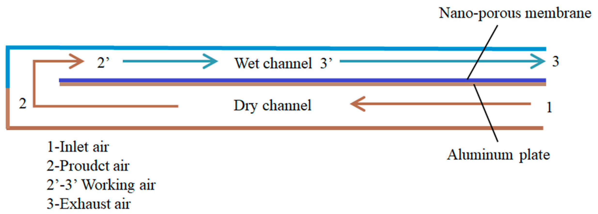
A plate counter-flow dew-point evaporative cooling system with a water-saturated nanoporous membrane applied to the surface of the wet channel has been designed in this paper, as illustrated in Figure 1. The system consists of a dry channel and a wet channel. Both of the channels are made of aluminum, and a thin aluminum plate has been installed in the middle of these two channels. The nanoporous membrane is covered the flowing path in the wet channel to improve the wettability. The main function of the membrane is to achieve uniform wettability in the wet channel. Therefore, the contact surface between the wet membrane and working air can be maximum, which can highly enhance the efficiency. Since the thickness of the membrane is only 0.1 mm, the thermal resistance is negligible.
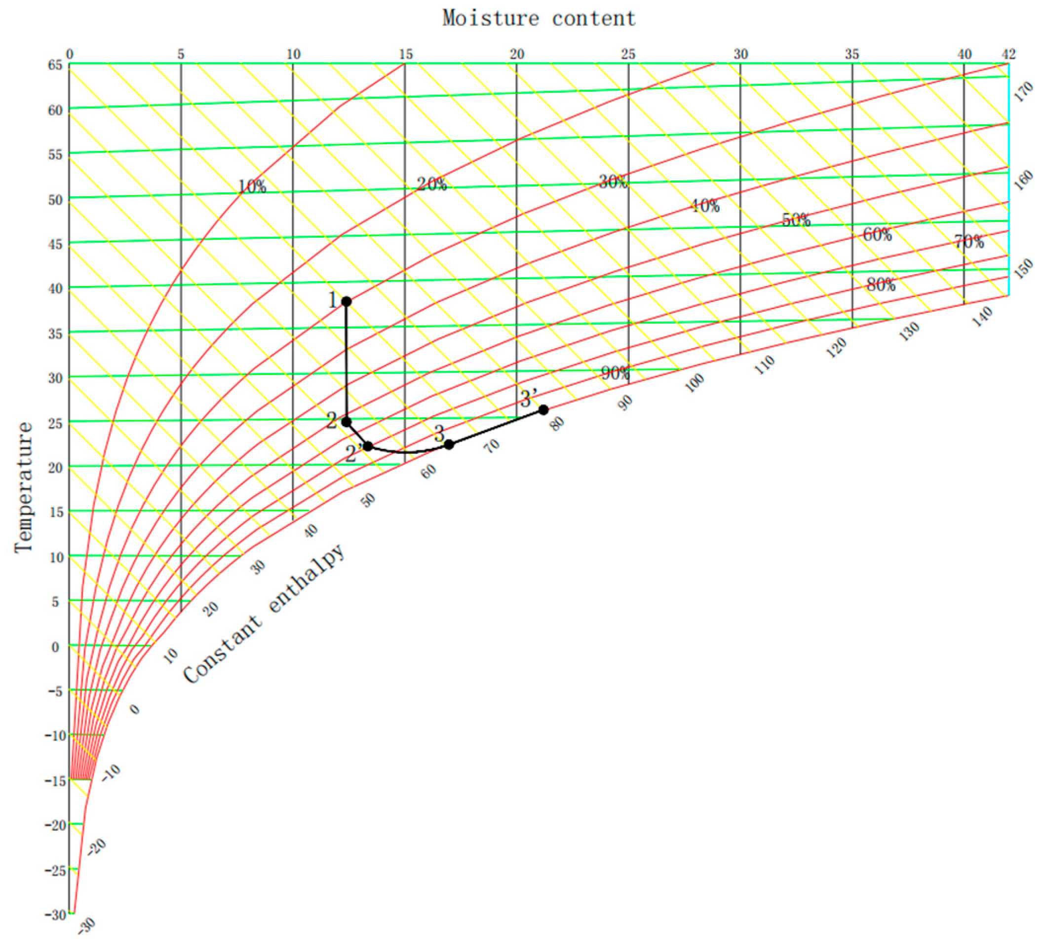
Meanwhile, a circulating water pipe with several holes on the surface is attached at the bottom of the wet channel to supply the cooling water. The water feeding needs to ensure that all surfaces in the wet channel are saturated. The cooling system operates in the following way: the supply air fan is used to transport the inlet air in the dry channel. Then, all inlet air is redirected into the wet channel through the small perforation, having direct contact with the nanoporous membrane, which is filled with water. The psychometric chart is shown in Figure 2. Point 2 stands for the product air’s condition. In order to gain the precise data of product air’s parameter, the product air is not released into the ambient air. The temperature of point 2 might theoretically reach that of the dew-point.
In the dry channel, the inlet air is continuously cooled down with constant moisture because of heat transfer between the wet and dry channels (states 1–2). The air in the dry channel is subsequently routed into the wet channel. The working air only encounters a latent heat exchange process with cooling water with constant enthalpy (state 2–2′) since the temperatures of 2 and 2′ are the same at the start. As the process goes on, the working air undergoes an enthalpy increase process and gradually achieves the saturated condition due to water evaporation and heat gains from the dry channel (state 2′–3′). Continuously, the saturated air’s temperature increases because of gaining heat from the dry channel. Simultaneously, the saturated air experiences latent heat exchange with cooling water, going through the condition from unsaturation to saturation time after time until being exhausted (3′–3).
2.2. Mathematical Analysis of Evaporative Cooling System
Based on the mass and heat transfer process and evaporative cooling system’s working principle, mathematical models of the heat and mass transfer process in the device have been established. The schematic diagrams of heat and mass transfer in dry and wet channels of the dew-point evaporative cooling device are shown in Figure 3.
Sensible heat exchange is the only factor to process air in the dry channel, so only heat transfer is taken into consideration. The following heat balancing equation and Newton’s cooling formula can be used to describe the heat transfer process.
In the wet channel, the enthalpy change is due to the exchange of sensible heat and latent heat, so both sensible and latent heat change of working air need to be calculated during the heat and mass transfer process. The whole process can be described as below:
A few assumptions have been made when applying the above equations:
(1) Since the thickness of the spacer plate is extremely thin, the heat conduction of the aluminum plate is ignored, which means .
(2) Only consider the heat and mass transfer in the vertical direction, and ignore its process in the flow direction.
(3) It is stipulated that the parameter of the wet channel’s inlet air is the same as the dry channel’s outlet air’s parameter.
As for this specific case, the calculation equations can be written in this way:
The whole heat and transfer process can be described as below:
As T3 < T1 in the equation, point 3 must gain more latent heat r in the evaporative cooling process. Therefore, the cooling part by evaporation is quite clear. Water evaporation is vital to this whole heat transfer process.
All of the above formulas depict the comprehensive heat and mass transfer mechanism, which occurs inside the dry and wet channels during dew-point evaporative cooling device operation. After analyzing the process through the mathematical aspects, it is known that several factors have a great impact on the heat and mass exchange process inside the dry and wet channels. Therefore, inlet air temperature, humidity, flow rate, cooling water volume, and transfer area are key factors. Especially, the study of heat transfer enhancement on the wet side is more critical.
3. Experimental Set-Up
3.1. Design Consideration
A plate counter-flow dew-point cooling device was designed and fabricated in the laboratory (Building heating and cooling system and material laboratory). Several sets of experimental studies were conducted to investigate the effects of various operating parameters on the overall performance of this new device. In order to gain the best performance, the structure design and some precautions are taken into consideration and summarized as follows:
(1) It is necessary to separate the wet channel from the dry channel to prevent the moisture from infiltrating into the dry channel. Therefore, the wet and dry channels are isolated by an aluminum plate.
(2) The wet and dry channels must be arranged in phases so that the air in the dry channel can be further cooled down. Consequently, the wet and dry channel structures are arranged in the form of counterflow. After the inlet air is dragged into the dry channel, the air is redirected into the wet channel through the small perforation, which is at the end of the dry channel.
(3) In order to enhance the heat and mass transfer, it is important to achieve a uniform wetting condition in the wet channel. As a result, a circulating water system has been installed inside the wet channel to make sure that the membrane is filled with cooling water.
(4) The geometric design of the configuration is based on many foreign experimental studies on dew-point evaporative cooling. It is known that the wet-bulb efficiency and cooling performance will be reduced if the dimension of channel space is too large. The reasonable channel height is approximately between 4 mm to 2 cm. Furthermore, the increase in channel length can extend the contact time of air and water in the wet channel giving rise to high efficiency.
3.2. Configuration Set-Up
The designed device consists of a counter-flow dew-point evaporative cooling module, constant-temperature water bath, fan, and circulating water pump, as shown in Figure 4.
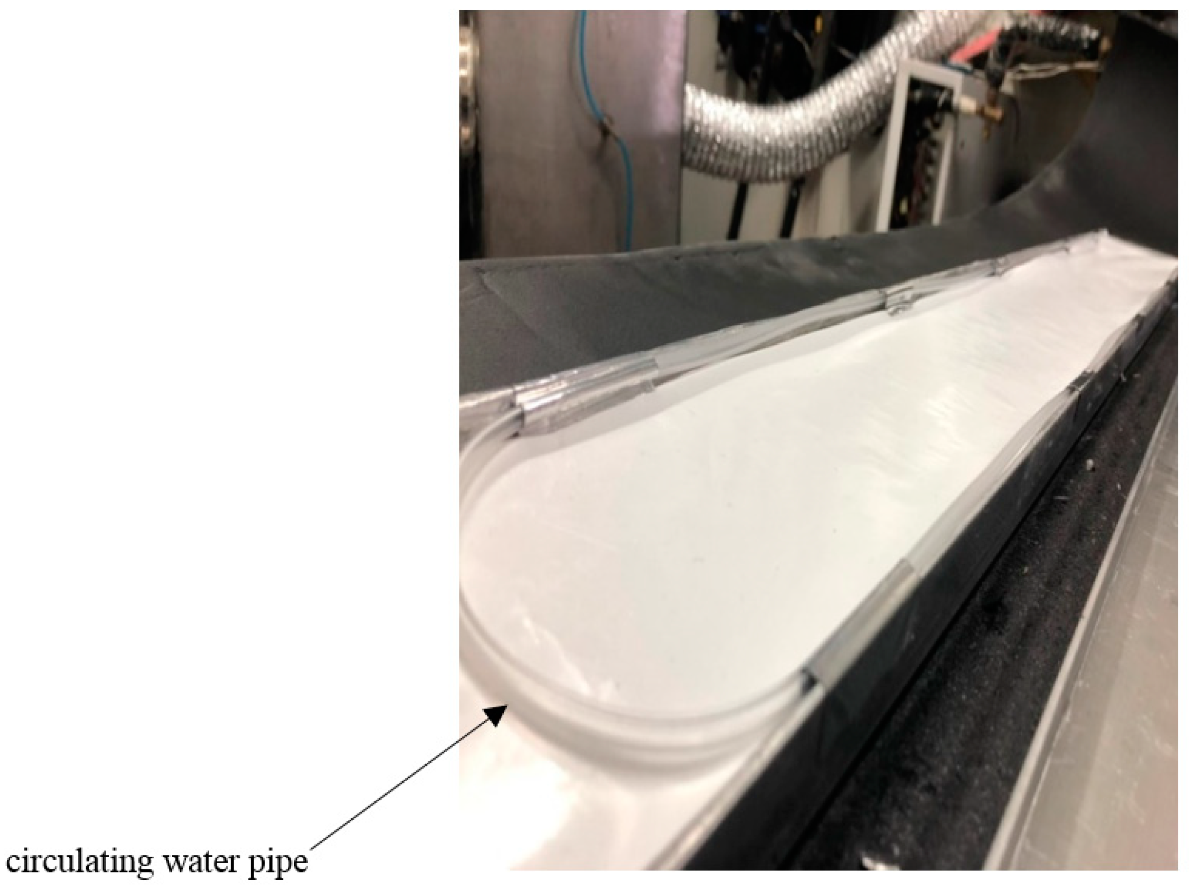
In the counter-flow dew-point evaporative cooling module, the uniform wetting condition in the wet channel is the key to enhancing heat and mass transfer. Therefore, the nanoporous membrane is covered at the bottom of the wet channel, and the circulating water system is installed. The circulating-water pipe with several tiny holes on the surface is fixed at the bottom of the wet channel, as indicated in Figure 5. The circulating water is provided by the water from a constant-temperature water bath, maintained at 15 °C. Several papers [15,16] have already demonstrated that water temperature has a negligible effect on the efficiency of this kind of cooling system. Therefore, the water temperature of the cooler is not discussed in this case.
The cooling water is pumped into the pipe at the beginning; then, the water is seeped through the small holes to moisturize the membrane to improve wettability. Then, a part of the water is absorbed by the membrane; the rest is recollected in the constant-temperature bath for circulation. The whole exchanger body is insulated by thermal insulation cotton to reduce heat loss.
The desired inlet air temperature and humidity are regulated by the laboratory since the building heating, cooling system, and material laboratory can adjust the indoor condition to achieve experimental requirements. The supply air rate is adjusted by the fan with a variable speed controller. The specifications of this cooling system are listed in Table 1.
3.3. Experimental Apparatus and Measurement Set-Up
To evaluate the performance, several experimental parameters were measured, including inlet air velocity, temperature, and relative humidity of inlet air, product air, and exhausted air. The velocity of inlet air was measured by hot-wire anemometer. The temperature of airflow was measured using K-type thermocouples. The K-type thermocouples were calibrated in advance and verified in an isothermal bath before the tests. The measurement locations are shown in Figure 6. The relative humidity of airflow was measured by a humidity probe with an accuracy of ±3%. The specification of measuring devices applied in this experiment are presented in Table 2. The values were recorded as long as the steady-state condition was reached with a relatively small variation of temperature and humidity. The detailed experimental conditions for research are summarized in Table 3.
3.4. Parameters of Membrane Material
The research of Zhu et al. [17] showed that the main factors affecting the heat and mass transfer effects of membrane materials are the water-holding capacity, durability, fouling resistance, and surface pore geometry of the material. Therefore, the membrane has the characteristics of strong water-holding capacity and wetting property, also easy to cut and cover on the aluminum plate, was first considered. According to this principle, a nanoporous membrane was finally selected as an ideal material to enhance the heat and mass transfer inside the wet channel of the dew-point evaporative cooling system.
The nanoporous membrane is composed of the porous surface layer and the bottom layer. The thickness of the surface layer is less than 0.1 μm, and the surface is filled with ordered micropores. The bottom layer thickness is 200–250 μm, which is made of materials with good water-holding capacity. When the liquid is absorbed into the pore, only small substances such as water vapor molecules can pass through, while the liquid is trapped on the outside side of the membrane. The parameters of the nanoporous membrane are shown in Table 4.
4. Uncertainty Analysis
The final results are significantly influenced by errors in instrument measurements during the experiment. Due to the existence of measurement error, the measured value is often not equal to the actual value, and the uncertainty analysis of the results also shows the reliability of the results. Therefore, uncertainty analysis of measuring apparatus and indirectly measured values is necessary.
The quadratic power method [18] is usually used to calculate the uncertainty. The calculation formula is as follows: Y is assumed to be a function of independent or uncorrelated variables, and then, the uncertainty of the indirect measurement parameter can be defined as:
where ΔY is the uncertainty of the dependent variable Y, and ΔX is the uncertainty of the independent variable X.
The relative uncertainty of Y is expressed as:
Calculate the uncertainty of dew-point efficiency and wet-bulb efficiency according to Equation (9). The parameters of the measuring instruments used in the experiment are listed in Table 2. When the dry channel inlet temperature of 40.36 °C, the outlet temperature of 27.8 °C, relative humidity of 40%, and inlet wind speed of 2 m/s, the uncertainties of wet-bulb efficiency and dew-point efficiency per unit area were as follows:
(1) Uncertainty of wet-bulb efficiency:
(2) Uncertainty of dew-point efficiency:
The absolute uncertainty and relative uncertainty consequences are listed in Table 5.
5. Discussion of Experiment Results
5.1. Performance Indicators of Counter-Flow Dew-Point Evaporative Cooling System
For the counter-flow dew-point evaporative cooling system, the temperature drop from inlet air temperature to outlet air temperature is the direct indices to evaluate cooling performance. In addition to the temperature drop, wet-bulb and dew-point efficiency are the other two representative indicators.
The equation can be expressed as follows. The ratio of the temperature difference between the inlet and outlet air temperatures to the temperature difference between the intake air temperature and its wet-bulb temperature is the wet-bulb efficiency, as shown in Equation (10).
Dew-point efficiency is defined as the ratio of the temperature difference between the inlet and outlet air temperatures to the temperature difference between the inlet air temperature and its dew-point temperature, as shown in Equation (11).
5.2. Comparison with the Non-Membrane Cooling System
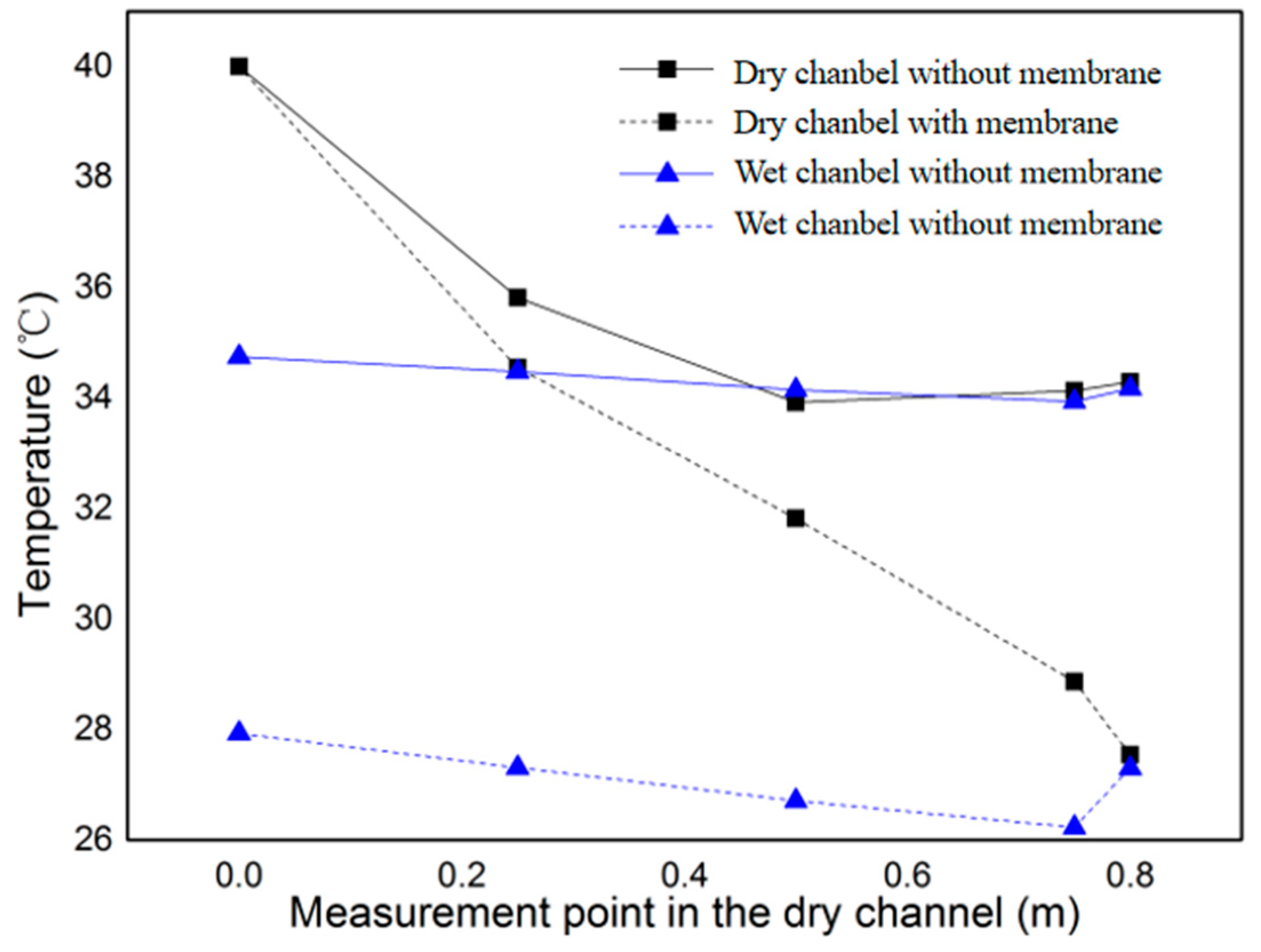
Figure 7 shows the measurement data of temperature tendency inside the dry and wet channel under the inlet air temperature of 40 °C, relative humidity of 30%, and air velocity of 2 m/s. It is obvious that the temperature is lower in the membrane-based cooling system. In the drying channel, the product air temperature of the membrane device is about 20% lower than that of the non-membrane device. In the wet channel, the air temperature of the membrane device is approximately 6 °C lower than the previous device without a membrane; therefore, it is significant to make use of the porous membrane due to the more serious heat and mass transfer process.
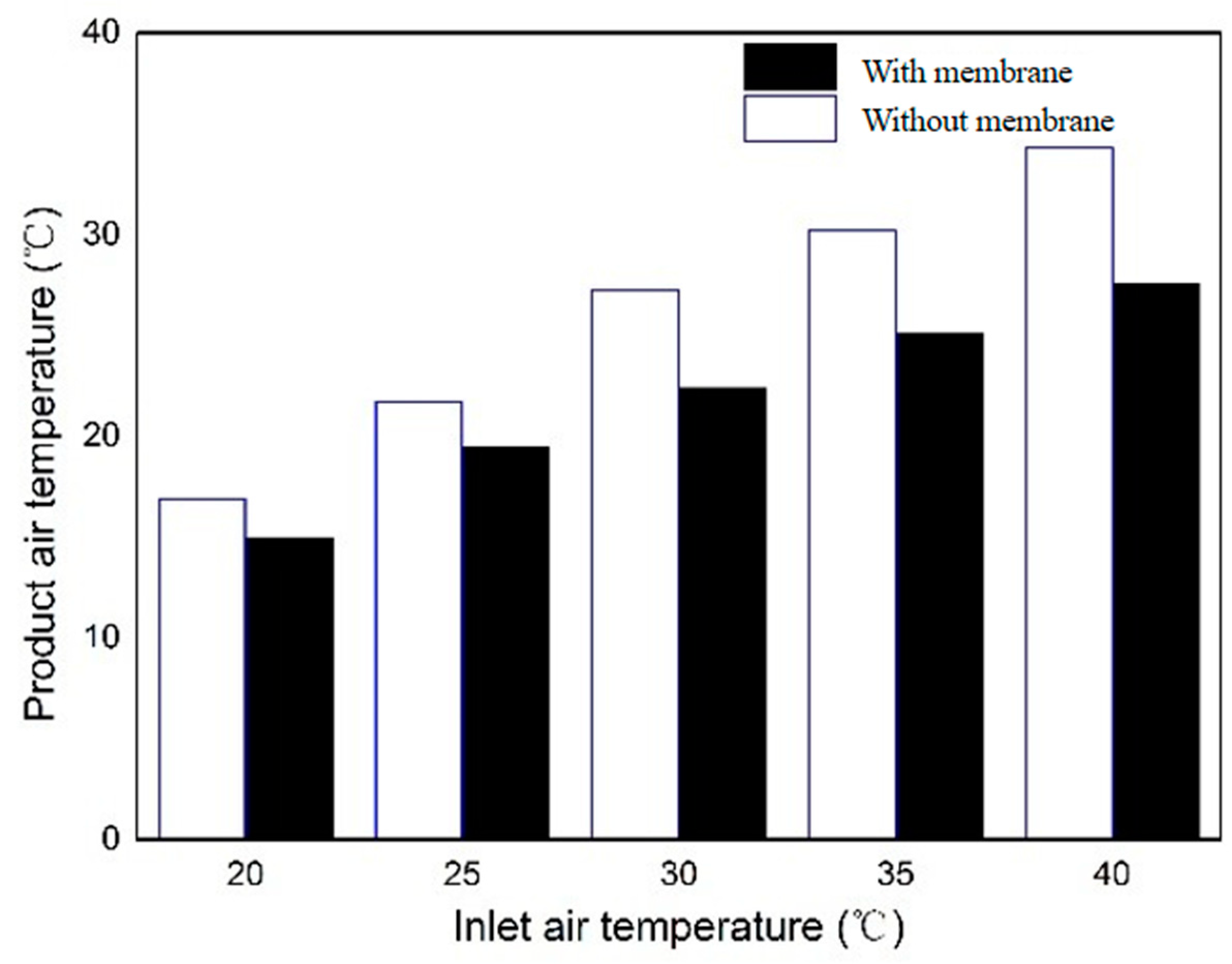
Figure 8 shows the difference in product air temperature with inlet air temperature changed under air velocity of 2 m/s and relative humidity of 30% in the two cooling systems. It can be noticed that the cooling performance of the dew-point evaporative cooling system can be dramatically enhanced by the utilization of the membrane. With the application of a membrane, the product air temperature is at least 2 °C lower than that without the membrane. Especially the higher the inlet temperature is, the larger temperature drop can be achieved with a nanoporous membrane. At the inlet temperature of 40 °C, the outlet temperature of the dry channel with a nanoporous membrane is 6 °C lower than that without a membrane. The principle is that the higher the inlet air temperature is, the greater the heat transfer temperature difference between dry and wet channels will be, which finally leads to a more obvious temperature drop. At the same time, the nanoporous membrane absorbs and spreads the cooling water in time to maximize the contact surface of heat and moisture exchange while ensuring the complete infiltration of the membrane.
The reason for this trend is due to the special characteristics of the membrane. In 2015, MIT [19] firstly proposed theoretical and mathematical research on the evaporation and the transport process within nanopores. According to lots of research [19,20,21,22], the schematic of the evaporation and transport process is shown in Figure 9.
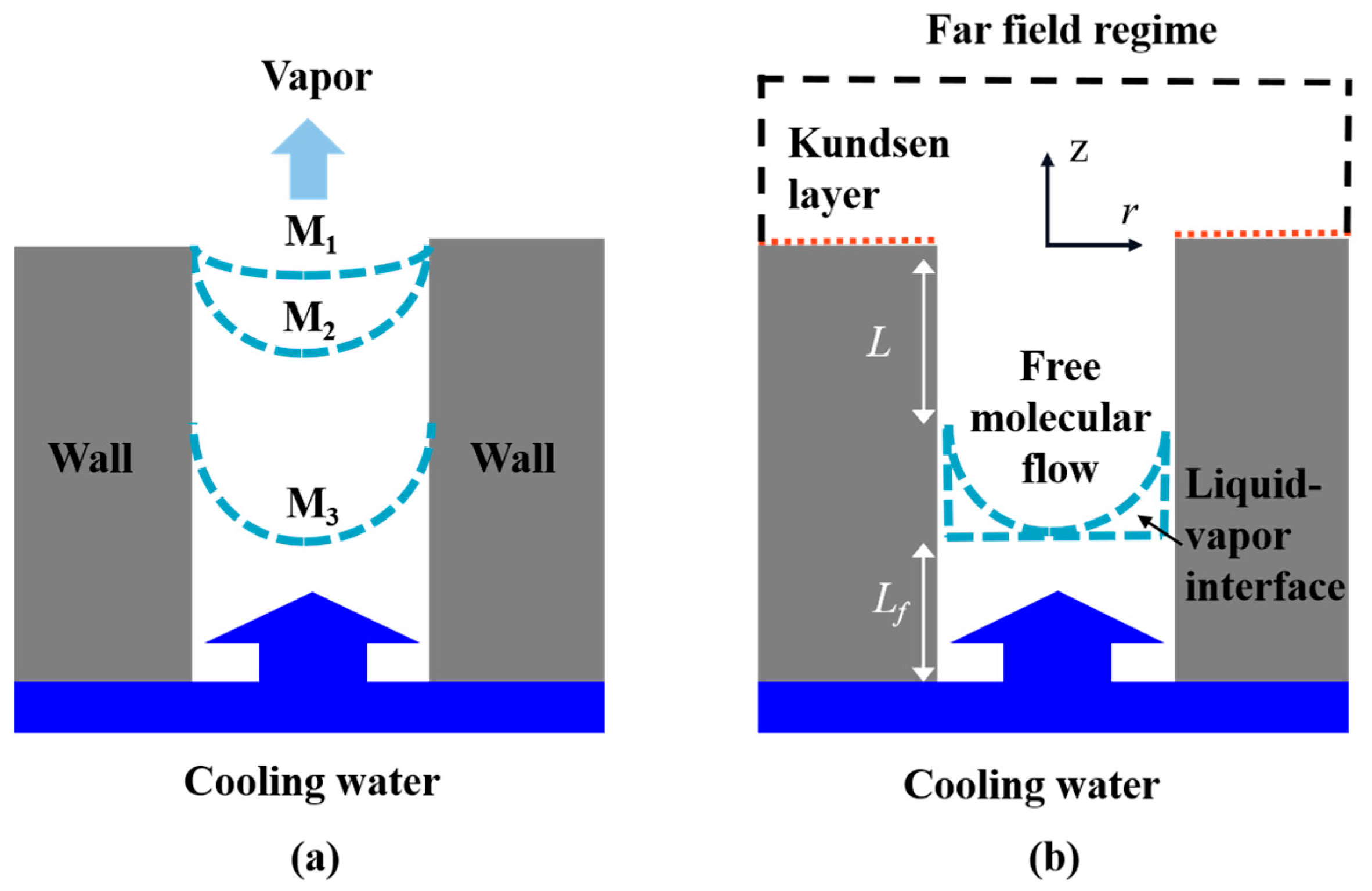
Figure 9a illustrates three shapes of the liquid–vapor interface under different working conditions. After the cooling water is absorbed by the membrane, it is sucked into the nanopores by the capillary pressure. Due to the viscous losses in the liquid phase and the wetting nature of the pore wall, there is a pressure difference in the liquid–vapor interface. When cooling water is sufficient, the interfacial pressure difference is relatively small, which leads to M1. Under this condition, the evaporation and mass transfer at the liquid–vapor interface is the most significant. As the cooling water evaporates, the shape of the interface gradually extends to the M2, and the maximum liquid–vapor pressure difference is formed. As the working conditions become more extreme, the shape of the interface will retreat to the M3. Within the pore, the liquid–vapor contact moves to self-adjust the transport resistance while maintaining the maximum pressure difference. The interface will sink to the bottom of the pore under more severe working conditions, resulting in full dryness. The vapor transfer track is seen in Figure 9b. During the evaporation process, it firstly transports from the free molecular regime, then across the Knudsen layer, and eventually to the far-field regime, reaching equilibrium.
After analyzing the evaporation and transfer characteristics within nanopores, one fact needs to be known that it is better to keep the liquid–vapor interface in the M1 position. Therefore, when sufficient cooling water is provided, the cooling performance will be much better. The cooling water can be quickly absorbed and spread to achieve uniform water distribution on the surface of the membrane. Meanwhile, the contact surface will be reached the maximum to have a better cooling effect. Under this condition, the water molecules in the liquid can be more easily leap into the vapor phase for a more thorough evaporation process, enhancing the heat and mass transfer process. To conclude, heat and mass transfer in the wet channel can be improved significantly with a nanoporous membrane applied. Therefore, the application of membrane can be considered an effective means for enhancing the cooling performance of a dew-point evaporative cooling system.
5.3. Effect of Inlet Air Temperature
After validating the better cooling effect of the proposed device, additional experimental experiments with the membrane-based dew-point evaporative cooling system were conducted for varied intake circumstances. The influence of inlet air temperature is the first consideration in this research.
The temperature trend in the dry channel under various inlet air temperatures is illustrated in Figure 10 with the inlet air velocity of 2 m/s and the relative humidity of 30%. It is found that the air temperature in the dry channel is observed to steadily decline along the flow direction, although the temperature lowering trend between neighboring measurement stations differed substantially. When the air just flows into the dry channel, the decreasing trend is much more obvious due to the larger temperature difference between the wet and dry channels. After that, the temperature difference becomes smaller as the air temperature in the dry channel gradually decreases, giving rise to a gentle, sensible heat exchange process.
As can be observed, the inlet temperature has a significant impact on the heat transfer performance of the device, particularly at higher inlet air temperatures. When the inlet air temperature is 40 °C, the temperature differential can reach 12.5 °C, whereas it is only 5 °C when the inlet air temperature is 20 °C. However, a 5 °C decline in temperature indicates a significant amount of cooling. Wet-bulb efficiency and dew-point efficiency follow the same pattern, as seen in Figure 11. It can be noticed that the efficiency is decreased with the temperature continuously dropping. With the decrease in inlet air temperature from 40 °C to 20 °C, the wet-bulb and dew-point efficiency are decreased progressively by 31% and 36%, respectively. The reason for this phenomenon is that the driving factor for sensible heat exchange is the temperature differential. When the inlet air temperature is high, the temperature difference between the wet and dry channel becomes large, contributing to a more serious heat transfer process.
5.4. Effect of Inlet Air Humidity
The relative humidity also has a great effect on heat and mass transfer inside the channel of the dew-point evaporative cooling system. As a result, experiments are carried out to determine the effect of relative humidity under the conditions of inlet air velocity of 2 m/s.
Comparing Figure 12 with Figure 10, the air temperature measured at low humidity is lower than that at high humidity in channels. Especially, the product air temperature with 30% relative humidity is much lower than that with 50% relative humidity. Since the humidity is low, the vapor pressure gradient is larger, which means a more severe heat and mass transfer reaction happened between cooling water and working air in the wet channel. For the dry channel, more sensible heat was transferred from the dry side to the wet side because more energy is needed for evaporation on the wet surface. Therefore, the inlet air with low humidity can be cooled down to a lower temperature.
Therefore, the lower the humidity of the inlet air is, the greater the temperature difference between the inlet and product air is, and the better the cooling effect is. Furthermore, when the inlet air temperature is high, the cooling performance is further enhanced under the low humidity condition. For instance, the air temperature drop can be achieved to 12.5 °C with low relative humidity, while only 8.5 °C is decreased under the high humidity condition. The effect of humidity on the temperature drop inside the wet channel is decreased with the inlet air temperature gradually reduced. This is because the temperature difference between the working air and wet surface is small when the inlet air temperature is low. Under this condition, less heat is required to evaporate the cooling water, implying that less heat is transported from the dry channel. The temperature difference is the driving force behind the entire heat and mass transfer process. As can be seen in the graph, the impact of humidity on the temperature drop is slight under the condition of 20 °C.
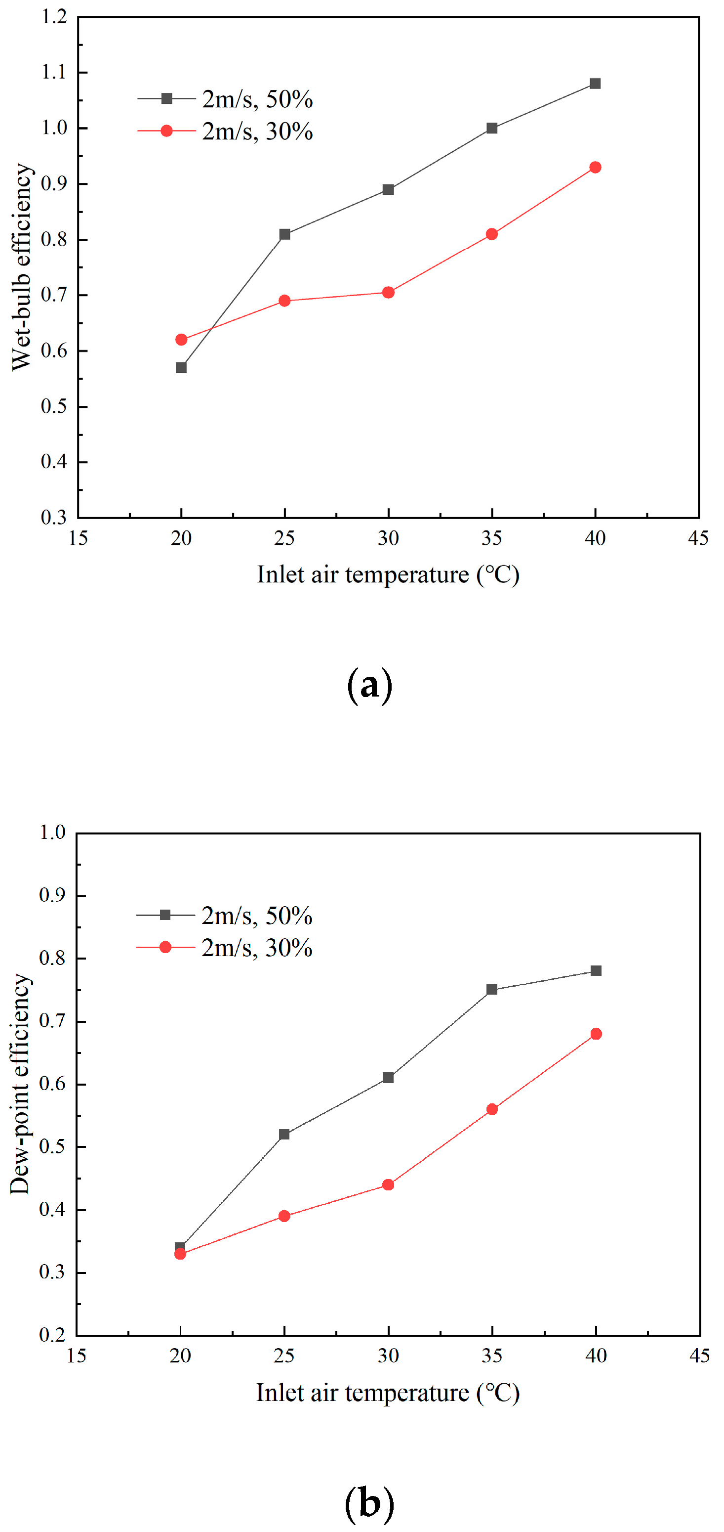
Another intriguing finding is that when the humidity is high, the wet-bulb efficiency and dew-point efficiency are greater, as illustrated in Figure 13. The temperature differential between the input air temperature and the corresponding wet-bulb temperature causes this trend (dew-point temperature). As the humidity decreases, the difference between these two temperatures increases, which leads to a decrease in efficiency according to Equations (10) and (11). However, the operating condition at the inlet air temperature of 20 °C shows different results due to experimental errors. In the large laboratory space, it is difficult to achieve low temperature and humidity working conditions.
5.5. Effect of Inlet Air Velocity
One of the most critical parameters impacting the heat exchange process in a dew-point evaporative cooling system is inlet air velocity. Figure 14 is obtained for the cooling effectiveness versus air velocity under the relative humidity of 30% and various inlet air temperature. When the inlet air temperature is 40 °C, it is discovered that the wet-bulb and dew-point efficiency can be enhanced to 11.8 and 15%, respectively, by lowering the input air velocity from 2 m/s to 1.5 m/s. Meanwhile, with the increase in the contact time between cooling water and working air, a thorough evaporation process can be realized; thus, the efficiency will be enhanced.
6. Conclusions
A plate counter-flow dew-point evaporative cooling device was designed and fabricated in this paper. With the application of nanoporous membrane, uniform wetting conditions can be achieved in the wet channel to improve the heat and mass transfer process. In addition, the working principle of the device and theoretical analysis of nanoporous membrane evaporation have been discussed in detail.
Firstly, several tests have been carried out to study the cooling performance effect of different operational settings. Then, temperature drop, wet-bulb efficiency, and dew-point efficiency are the three main indices to indicate cooling performance. Finally, a few conclusions can be drawn as below. The application of membrane can significantly enhance the heat and mass exchange and improve the cooling performance. With the utilization of membrane, the maximum temperature drop in the dry channel can reach 12.5 °C, which is 50% larger than that under the non-membrane condition. The reason is due to the membrane’s high water absorption and retention characteristic. Higher inlet air temperature condition leads to greater temperature drop. When the inlet temperature is 40 °C, the temperature difference between inlet air and product air can reach 12.5 °C. Lower humidity can achieve a larger temperature drop while lower cooling effectiveness. The wet-bulb and dew-point efficiency can reach 1.09 and 0.79, respectively, under 50% humidity conditions, which is higher than that under 30% relative humidity. The inlet air velocity should be controlled at a low speed to increase more contact time between wet surface and working air. When the inlet air temperature was 40 °C and velocity was reduced from 2 m/s to 1.5 m/s, the wet-bulb and dew-point efficiency rose by 11.8% and 15%, respectively.
The process of heat and mass transfer in porous membranes is vitally important. Simulation can provide a deeper understanding of the basic transport phenomena. In future simulation research, we should focus on simulating the evaporation phase transition of water in porous membranes and the convective heat transfer process with secondary air.
Author Contributions
Conceptualization, J.L. and B.Z.; methodology, J.L.; validation, M.Z. and W.X.; writing—original draft preparation, B.Z.; writing—review and editing, J.L. and E.H.; All authors have read and agreed to the published version of the manuscript.
Funding
This research received no external funding.
Institutional Review Board Statement
Not applicable.
Informed Consent Statement
Not applicable.
Data Availability Statement
Not applicable.
Conflicts of Interest
The authors declare no conflict of interest.
Nomenclature
| A | Area (m2) |
| cp | Specific heat capacity of moist air (J/kg·K) |
| d | Humidity ratio (g/kg dry air) |
| h | Convective heat transfer coefficient (W/m2·K) |
| hm | Convective mass transfer coefficient in wet channel (W/m2·K) |
| i | Specific enthalpy (J/kg) |
| M | Mass flow rate (kg/s) |
| Q | Rate of heat transfer (W) |
| r | Latent heat of vaporization of water (kJ/kg) |
| t | Temperature (℃) |
| T | Temperature (K) |
| Tpl | Temperature of aluminum plate (K) |
| Twater | Temperature of circulating water (K) |
| Special characters | |
| Humidity ratio (kg water vapor/kg dry air) | |
| Dew-point efficiency (-) | |
| Wet-bulb efficiency (-) | |
| subscripts | |
| 1 | Dry channel inlet air |
| 2 | Dry channel outlet air |
| 3 | Wet channel exhaust air |
| d | Dry channel |
| db | Dry bulb |
| w | Wet channel |
| wb | Wet bulb |
References
- Zhang, L.; Li, Y. On analysis of energy-saving design of heating ventilation and air conditioning. Shanxi Archit. 2010, 36, 185–187. [Google Scholar]
- Shen, J.F. Energy conservation-main trend of air-conditioning industry. J. HVAC 2004, 2, 18–22. [Google Scholar]
- Asdrubal, F.; D’Alessandro, F.; Schiavoni, S. A review of unconventional sustainable building insulation materials. Sustain. Mater. Technol. 2015, 4, 1–17. [Google Scholar] [CrossRef]
- Duan, Z.; Zhan, C.; Zhao, X.; Dong, X. Experimental study of a counter-flow regenerative evaporative cooler. Build. Environ. 2016, 104, 47–58. [Google Scholar] [CrossRef]
- Wu, J.M.; Huang, X.; Zhang, H. Theoretical analysis on heat and mass transfer in a direct evaporative cooler. Appl. Therm. Eng. 2009, 29, 980–984. [Google Scholar] [CrossRef]
- Maheshwari, G.P.; Al-Ragon, F.; Suri, R.K. Energy saving potential of indirect evaporative cooler. Appl. Energy 2001, 69, 69–76. [Google Scholar] [CrossRef]
- Stoitchkov, N.J.; Dimitrov, G.I. Effectiveness of crossflow plate heat exchanger for indirect evaporative cooling. Int. J. Refrig. 1998, 21, 463–471. [Google Scholar] [CrossRef]
- Zhou, D.H.; Huang, X.; Fan, K. A comparative analysis of configuration on dew point evaporative cooler. Fuild Mach. 2013, 41, 71–77. [Google Scholar]
- Huang, X.; Liu, X.W.; Wu, Z.X.; Huang, H.L. Experiments on dew-point indirect-direct evaporative cooling air conditionding unit. J. HVAC 2011, 41, 104–108. [Google Scholar]
- Anisimov, S.; Pandelidis, D.; Danielewicz, J. Numerical analysis of selected evaporative exchangers with the Maisotsenko cycle. Energy Convers. Manag. 2014, 88, 426–441. [Google Scholar] [CrossRef]
- Cui, X.; Chua, K.J.; Yang, W.M. Numerical simulation of a novel energy-efficient dew-point evaporative air cooler. Appl. Energy 2014, 136, 979–988. [Google Scholar] [CrossRef]
- Dizaji, H.S.; Hu, E.J.; Chen, L. A comprehensive review of the Maisotsenko-cycle based air conditioning systems. Energy 2018, 156, 725–749. [Google Scholar] [CrossRef] [Green Version]
- Johnson, D.W.; Yavuzturk, C.; Pruis, J. Analysis of heat and mass transfer phenomena in hollow fiber membranes used for evaporative cooling. J. Membr. Sci. 2003, 227, 159–171. [Google Scholar] [CrossRef]
- Lu, Z.M.; Salamon, T.R.; Narayanan, S.; Bagnall, K.R. Design and Modeling of Membrane-Based Evaporative Cooling Devices for Thermal Management of High Heat Fluxes. IEEE Trans. Compon. Packag. Manuf. Technol. 2016, 6, 1056–1065. [Google Scholar] [CrossRef] [Green Version]
- Dizaji, H.S.; Hu, E.J.; Chen, L.; Samira, P. Development and validation of an analytical model for perforated (multi-stage) regenerative M-cycle air cooler. Appl. Energy 2018, 228, 2176–2194. [Google Scholar] [CrossRef]
- Dizaji, H.S.; Hu, E.J.; Chen, L.; Samira, P. Analytical/experimental sensitivity study of key design and operational parameters of perforated Maisotsenko cooler based on novel wet-surface theory. Appl. Energy 2020, 262, 114557. [Google Scholar] [CrossRef]
- Zhu, Z.X. The relationship between hydrophilicity of membrane material, wettability of membrane surface to water and water contact angle. J. Membr. Sci. 2014, 34, 3–6. [Google Scholar]
- Pacak, A.; William, W. Review of Dew Point Evaporative Cooling Technology for Air Conditioning Applications. Appl. Sci. 2021, 11, 934. [Google Scholar] [CrossRef]
- Lu, Z.; Narayanan, S.; Wang, E.N. Modeling of Evaporation from Nanopores with Nonequilibrium and Nonlocal Effects. Langmuir 2015, 36, 9817–9824. [Google Scholar] [CrossRef]
- Jing, L.; Xu, H.D.; Zhu, M.Y.; Dai, Y.W.; Liu, H.Z.; Li, Z. The performance and model of porous materials in the indirect evaporative cooling system: A review. J. Build. Eng. 2021, 41, 102741–102763. [Google Scholar]
- Narayanan, S.; Fedorov, A.G.; Joshi, Y.K. Interfacial Transport of Evaporating Water Confined in Nanopores. Langmuir 2011, 27, 10666–10676. [Google Scholar] [CrossRef] [PubMed]
- Huang, X.M.; Wu, J.Q.; Liu, W.; Yu, B.M. Effect of heat and mass transfer of thin film region on the stability of capillary evaporating meniscus. Chin. J. Aeronaut. 2013, 34, 873–879. [Google Scholar]
Figure 1.
Working principle of membrane-based dew-point evaporative cooling system.

Figure 2.
The theory of dew-point evaporative cooling.

Figure 3.
(a) The heat transfer process in dry channel; (b) the heat and mass transfer process in wet channel.
Figure 3.
(a) The heat transfer process in dry channel; (b) the heat and mass transfer process in wet channel.

Figure 4.
Prototype of membrane-based dew-point evaporative cooling system.

Figure 5.
Configuration of circulating water pipe.

Figure 6.
Measurement location.

Figure 7.
Temperature tendency inside the wet and dry channels.

Figure 8.
Product air temperature under various inlet air temperature conditions.

Figure 9.
Evaporation process from a nanopore: (a) three shapes of the liquid-vapor interface; (b) the vapor transfer track.
Figure 9.
Evaporation process from a nanopore: (a) three shapes of the liquid-vapor interface; (b) the vapor transfer track.

Figure 10.
The temperature tendency in the dry channel for different inlet air temperatures.

Figure 11.
Wet-bulb and dew-point efficiency under different inlet air temperature conditions.

Figure 12.
Temperature tendency in the channel under different humidity conditions.

Figure 13.
(a) Wet-bulb efficiency under different humidity conditions and (b) dew-point efficiency under different humidity conditions.
Figure 13.
(a) Wet-bulb efficiency under different humidity conditions and (b) dew-point efficiency under different humidity conditions.

Figure 14.
(a) Wet-bulb efficiency under different inlet air velocities and (b) dew-point efficiency under different inlet air velocities.
Figure 14.
(a) Wet-bulb efficiency under different inlet air velocities and (b) dew-point efficiency under different inlet air velocities.


Table 1.
Geometric size for the membrane-based dew-point evaporative cooling system.
| Parameter | Unit | Size |
|---|---|---|
| Channel length | mm | 1000 |
| Channel width | mm | 80 |
| Channel spacing | mm | 10 |
| Middle plate length | mm | 920 |
| Plate thickness | mm | 2 |
| Thickness of PSE 300 membrane | mm | 0.1 |
| Length of PSE 300 membrane | mm | 920 |
| Width of PSE 300 membrane | mm | 80 |
| Inner diameter of circulating water pipe | mm | 2 |
| Thickness of insulation material | mm | 20 |
Table 2.
Specification of experimental apparatus.
| Parameter | Apparatus | Accuracy | Measurement Range |
|---|---|---|---|
| Temperature | K-type thermocouples | ±0.2 °C | 0–100 °C |
| Thermometer (testo 610) | ±0.5 °C | −10–50 °C | |
| Relative humidity | Humidity probe (GSP-6) | ±3% RH | 20–95% RH |
| Airflow velocity | Hotwire anemometer (testo 425) | ±(0.03 m/s + 5% of mv) | 0–20 m/s |
Table 3.
Detailed experimental conditions for research.
| Working Condition | Experimental Details |
|---|---|
| Inlet air temperature (dry-bulb) | 20, 25, 30, 35, 40 °C |
| Inlet air relative humidity | 20–30% (low moisture), 50–60% (high moisture) |
| Inlet air velocity | 1.5, 2 m/s |
Table 4.
Parameters of the nanoporous membrane.
| Nanoporous Membrane | Technical Parameters | |||
|---|---|---|---|---|
| Ultrafiltration membrane (PSE300) | Pore size (µm) | Porosity (-) | Single thickness (mm) | Pure water flux (L/s) |
| 0.03 | 93–98% | 0.1 | 18 | |
Table 5.
Results of uncertainty analysis (T1 = 40.36 °C, T3 = 27.8 ℃, v = 2 m/s).
| Performance Parameters | Calculated Value | Absolute Uncertainty | Relative Uncertainty |
|---|---|---|---|
| (wet-bulb efficiency) | 0.93 | ±0.0285 | ±5.73% |
| (dew-point efficiency) | 0.64 | ±0.0247 | ±4.86% |
Publisher’s Note: MDPI stays neutral with regard to jurisdictional claims in published maps and institutional affiliations. |
© 2022 by the authors. Licensee MDPI, Basel, Switzerland. This article is an open access article distributed under the terms and conditions of the Creative Commons Attribution (CC BY) license (https://creativecommons.org/licenses/by/4.0/).
Share and Cite
MDPI and ACS Style
Lv, J.; Zhou, B.; Zhu, M.; Xi, W.; Hu, E. Experimental Study on the Performance of a Dew-Point Evaporative Cooling System with a Nanoporous Membrane. Energies 2022, 15, 2592. https://0-doi-org.brum.beds.ac.uk/10.3390/en15072592
AMA Style
Lv J, Zhou B, Zhu M, Xi W, Hu E. Experimental Study on the Performance of a Dew-Point Evaporative Cooling System with a Nanoporous Membrane. Energies. 2022; 15(7):2592. https://0-doi-org.brum.beds.ac.uk/10.3390/en15072592
Chicago/Turabian StyleLv, Jing, Bo Zhou, Mengya Zhu, Wenhao Xi, and Eric Hu. 2022. "Experimental Study on the Performance of a Dew-Point Evaporative Cooling System with a Nanoporous Membrane" Energies 15, no. 7: 2592. https://0-doi-org.brum.beds.ac.uk/10.3390/en15072592
Note that from the first issue of 2016, this journal uses article numbers instead of page numbers. See further details here.