
Selection of Inertial and Power Curtailment Control Methods for Wind Power Plants to Enhance Frequency Stability


1
School of Electrical & Electronic Engineering, Yonsei University, Seoul 03722, Korea
2
Division of Electrical, Electronic & Control Engineering, Kongju National University, Cheonan 31080, Korea
*
Authors to whom correspondence should be addressed.
Energies 2022, 15(7), 2630; https://0-doi-org.brum.beds.ac.uk/10.3390/en15072630
Submission received: 7 March 2022
/
Revised: 29 March 2022
/
Accepted: 31 March 2022
/
Published: 3 April 2022
(This article belongs to the Special Issue Electrical Power System Dynamics: Stability and Control)
Abstract
:As renewable energy penetrates the power system, system operators are required to curtail output power from generation units to balance the power supply and demand. However, large curtailment from wind power plants (WPPs) may instantly cause excessive output power decrement, causing system frequency to drop significantly before reaching its nominal value. In order to solve this problem, this paper proposes a cooperative control framework to determine the operation of WPPs in two control methods, which are the stepwise inertial control (SIC) method and the curtailed control method. The proposed framework first determines the WPPs to operate in the curtailed control method to provide the required power curtailment. Next, it determines the WPPs to operate in the SIC method considering their releasable kinetic energy to provide an effective inertial response and compensate for the sudden excessive output power decrement caused by other WPPs operated in the curtailed control method. Therefore, each WPP is operated in one of two control methods to provide required power curtailment while reducing the sudden excessive output power decrement. To verify the effectiveness of the proposed cooperative control framework, several case studies are carried out on the practical South Korea electric power system.
1. Introduction
Worldwide, many countries are installing the high penetration of renewable energy, especially wind and solar, for the transition to renewable energy sources. According to the report from the International Renewable Energy Agency (IRENA) [1], the capacity of renewable energy in 2020 was 291.7 GW in the United States, 100.6 GW in Canada, 55.4 GW in France, 47.4 GW in the United Kingdom, 32.9 GW in Sweden, 894.9 GW in China, 103.5 GW in Japan, and 134.3 GW in India. In particular, the renewable energy capacity of South Korea in 2020 was 21 GW, and the wind and photovoltaic take the largest portion. Moreover, the South Korean government has planned to increase the renewable energy generation rate to 20% by 2030. To do so, they are planning to install wind power plants (WPPs) and photovoltaic up to 17.7 and 5.7 GW, respectively, until 2030.
However, many studies have reported that high renewable energy penetration may cause several stability problems [2,3,4,5,6]. In terms of frequency stability, the renewable energy penetration replaces the conventional synchronous generators (SGs) participating in various ancillary services, resulting in various frequency stability problems. For example, when a large disturbance occurs in the power system, conventional SGs provide power reserve and inertial response (IR) to support the frequency stability. However, distributed generators (DGs) normally operate on the maximum power point tracking (MPPT) control method, which cannot provide additional frequency stability support. Therefore, the penetration of DGs operating on this control method decreases the frequency stability supports.
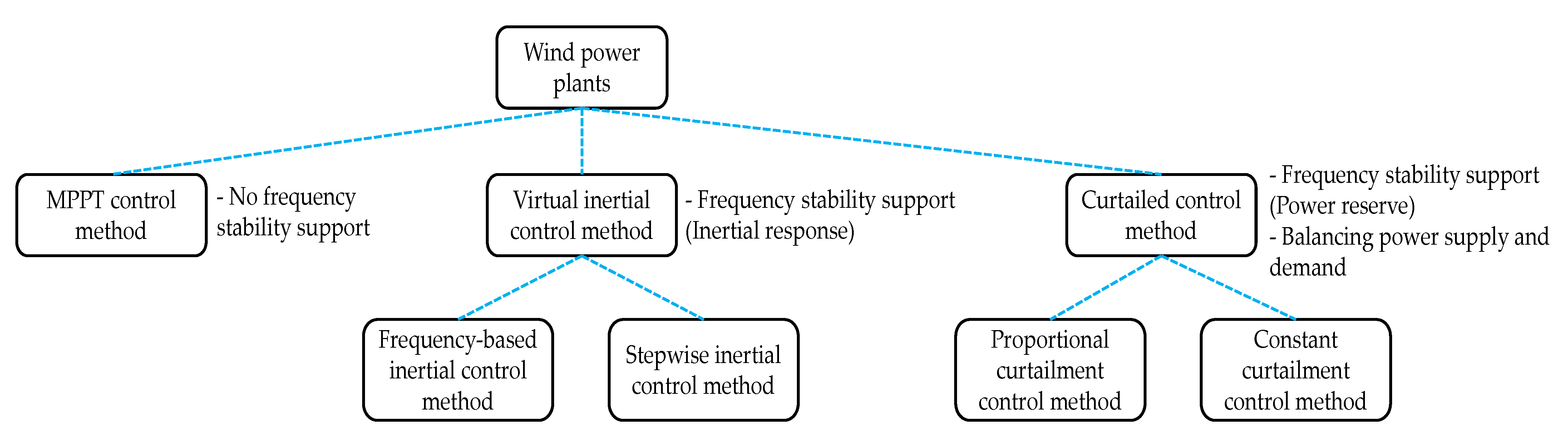
For the power system with a low wind power penetration level (WPPL), the WPPs operating in the MPPT control method have caused a minor frequency stability problem. However, as WPPL increases, WPPs operating on this control method are causing severe frequency stability problems [7]. Moreover, the variability and uncertainty of renewable energy resources are causing severe problems in the power supply and demand. Therefore, the system operator may require WPPs to operate in different control methods other than the MPPT control method to provide frequency stability support [8,9] and curtail a certain amount of power to maintain the power balance [10]. The control methods for WPPs other than the MPPT control method are summarized in Figure 1.
To solve the frequency stability problem caused by high WPPL, researchers have developed a control method for WPPs to provide IR. In order to provide IR by WPPs, there are two types of virtual inertial control (VIC) methods, which are the frequency-based inertial control (FBIC) method and the stepwise inertial control (SIC) method [11,12,13]. These two control methods provide the IR by the kinetic energy from the WPPs. However, while the former provides the IR based on system frequency change, the latter is independent of the system frequency change and provides the IR according to its control scheme. Therefore, the SIC method is applied more variously for applications.
On the other hand, WPPs operated by the curtailed control method can provide power reserve when a disturbance occurs in the power system. For the curtailed control method, there are proportional curtailment control (PCC) and constant curtailment control (CCC) methods [14]. The former curtails the output power of WPP according to its proportional coefficient. Therefore, depending on the wind speed, the size of the power curtailment differs. On the other hand, the latter curtails constant output power.
Moreover, as the WPPL increases, maintaining the balance between power supply and demand is becoming more important than ever. Moreover, the amount of required power curtailment increases for high WPPL. However, excessive output power decrement instantly occurs from WPPs in the process of switching from the MPPT control method to the curtailed control method. As a result, this causes the system frequency dip before reaching its nominal value. In particular, if this frequency dip is beyond the dead-band of the governor, it will cause other SGs to compensate for the power loss. This paper proposes the design of a cooperative control framework, which determines each WPP operation in curtailed control and SIC methods. Therefore, when system operators require power curtailment to maintain the power balance, the WPPs operating by the former provide the required power curtailment, and other WPPs operating by the latter compensate for the excessive output power decrement by IR.
This paper is organized as follows. Section 2 describes the operation of the WPPs, including MPPT control, curtailed control, and SIC methods. In Section 3, the proposed cooperative control framework implementation is described with its theoretical analysis. Section 4 describes the characteristics of the practical South Korea electric power system and verifies the effectiveness of the proposed framework with several case studies using the DIgSILENT PowerFactory® (Version 2018, DIgSILENT GmbH, Gomaringen, Germany) [15]. Finally, conclusions are given in Section 5.
2. Wind Power Plants Operation
2.1. Characteristics of Permanent Magnet Synchronous Generator and MPPT Control Method
In this paper, a type-4 wind turbine generator, which is a permanent magnet synchronous generator (PMSG), is considered for wind power. Generally, PMSG consists of a rotor side converter (RSC), DC-link circuit with a capacitor, and grid side converter (GSC) [16]. Moreover, the PMSG control system provides a reference signal for pitch control, RSC control, and GSC control methods. Furthermore, depending on the power system condition, the active power reference (Pref) is determined based on MPPT control, VIC, and curtailed control methods.
Besides the power reference determined by each control method, the mechanical power from the wind source is obtained and calculated as
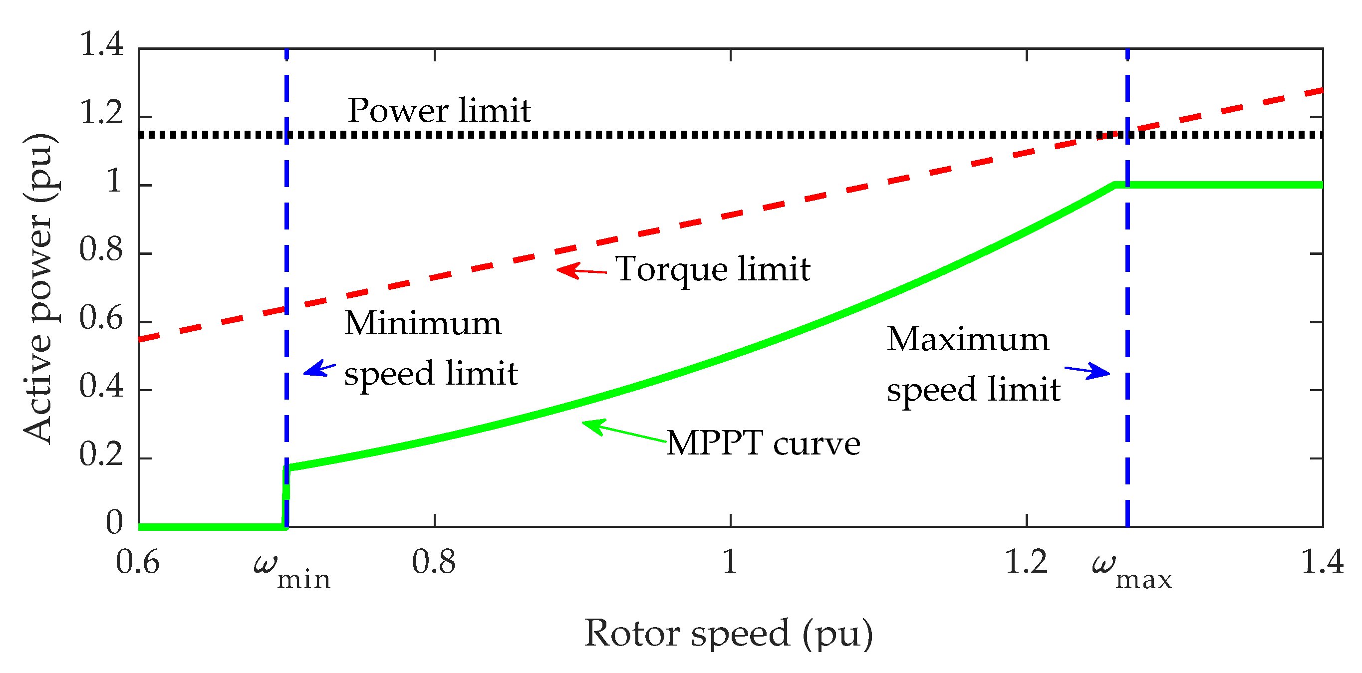
where Pmec is the mechanical power extracted from the wind, ρ is the air density of 1.225 kg/m3, R is the rotor radius of 46.5 m, Vwind is the wind speed, and CP is the power coefficient based on tip speed ratio (λ) and pitch angle (β). Normally, WPPs are operated by the MPPT control method to provide maximum power in a steady state [17]. As shown in Figure 2, the active power reference is determined by the MPPT curve, PMPPT, when rotor speed (ωr) is between the minimum speed limit (ωmin) and maximum speed limit (ωmax). Moreover, PMPPT is calculated as
where CP,opt and λopt are the optimal CP and λ values determined by the MPPT control method, respectively, and kopt is the coefficient of the MPPT curve. In this paper, CP,opt is set to 0.447 with β at 0 and λopt at 7.2.
2.2. Curtailed Control Method
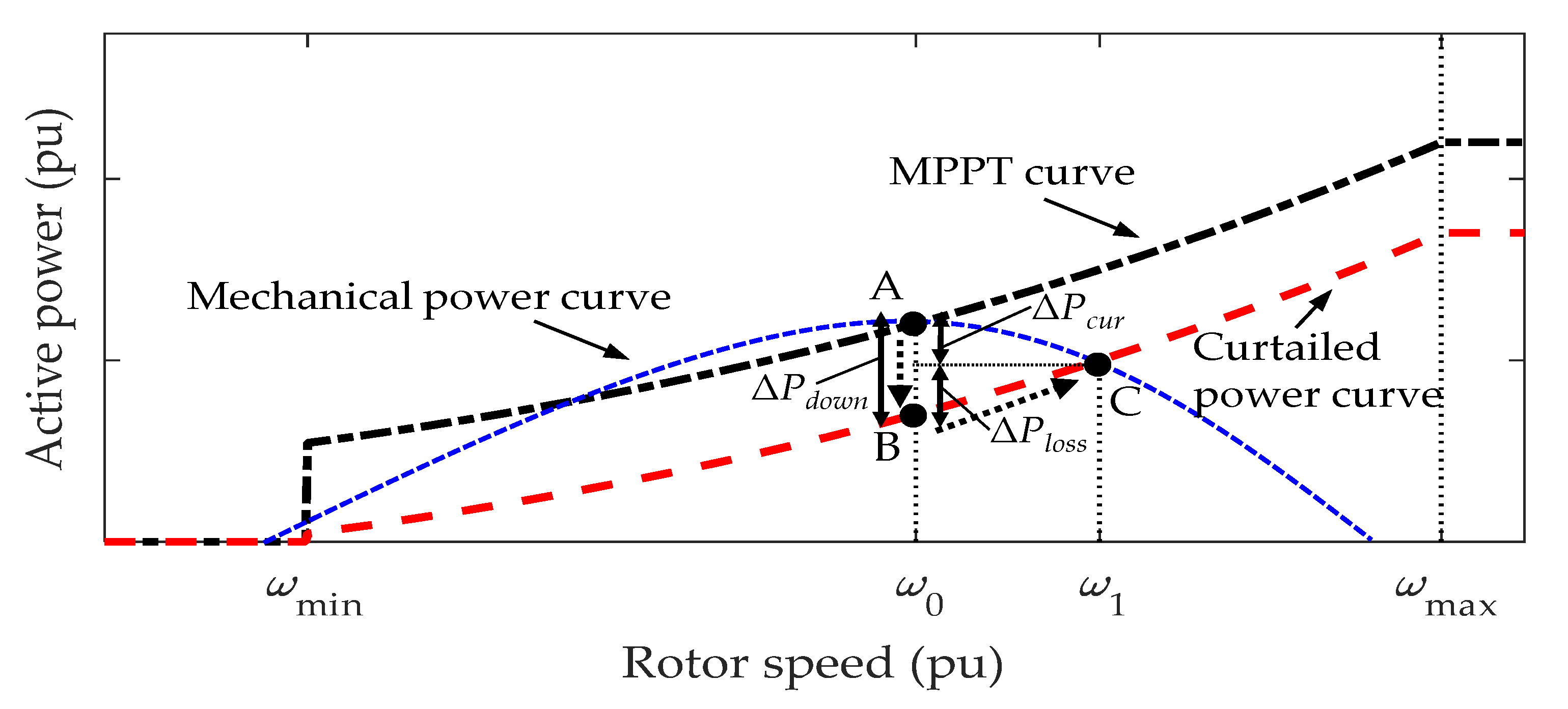
As system operators need to maintain the power balance, they may require WPPs to operate in the curtailed control method considering the wind condition. As mentioned previously, there are CCC and PCC methods to curtail output power from WPPs. However, power curtailment by the former method is only available at a specific output power level [14]. Therefore, the latter method is preferably applied to curtail output power from WPPs. The curtailed power using the PCC method is defined as
where Pcur is the power reference by the PCC method and αcur is the coefficient for the curtailed power curve. Therefore, when WPP switches from the MPPT control method to the PCC method, the output power decreases by ΔPdown as
As shown in Figure 3, the output power is decreased from point A to B when WPP is switched from the MPPT control method to the PCC method. However, the output power cannot maintain the power at point B. This is because a difference exists between the mechanical power and active power reference. Therefore, the rotor speed is accelerated by the swing equation as
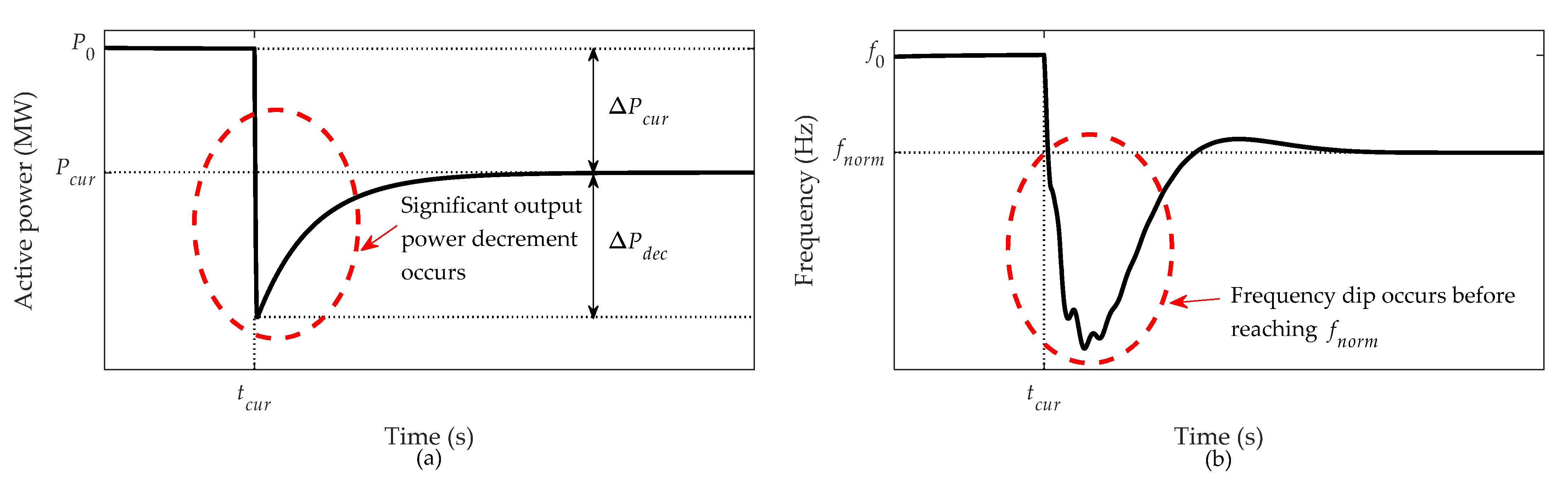
where H is the inertia constant of the PMSG. As a result, the rotor speed is accelerated from point B to C, which is the intersection of the Pref and Pmec. Therefore, it can be concluded that when WPP switches from the MPPT control method to the curtailed control method, the active power immediately decreases from point A to B and then reaches point C. In other words, when WPPs are required to curtail by ΔPcur, the unwanted power decrement of ΔPdec occurs. Moreover, ΔPdec becomes significant as WPPL and the required power curtailment increases.
2.3. Virtual Inertial Control Method
While conventional SGs provide various frequency responses, such as power reserve and IR, renewable energy-based DGs are less capable of providing these frequency responses. However, recent studies have developed a VIC method for WPPs to provide IR with the releasable kinetic energy stored in the rotating rotor. Therefore, WPPs can provide similar IR as conventional SGs and support frequency stability when a large disturbance, such as a generation trip occurs in the power system [11,12,13].
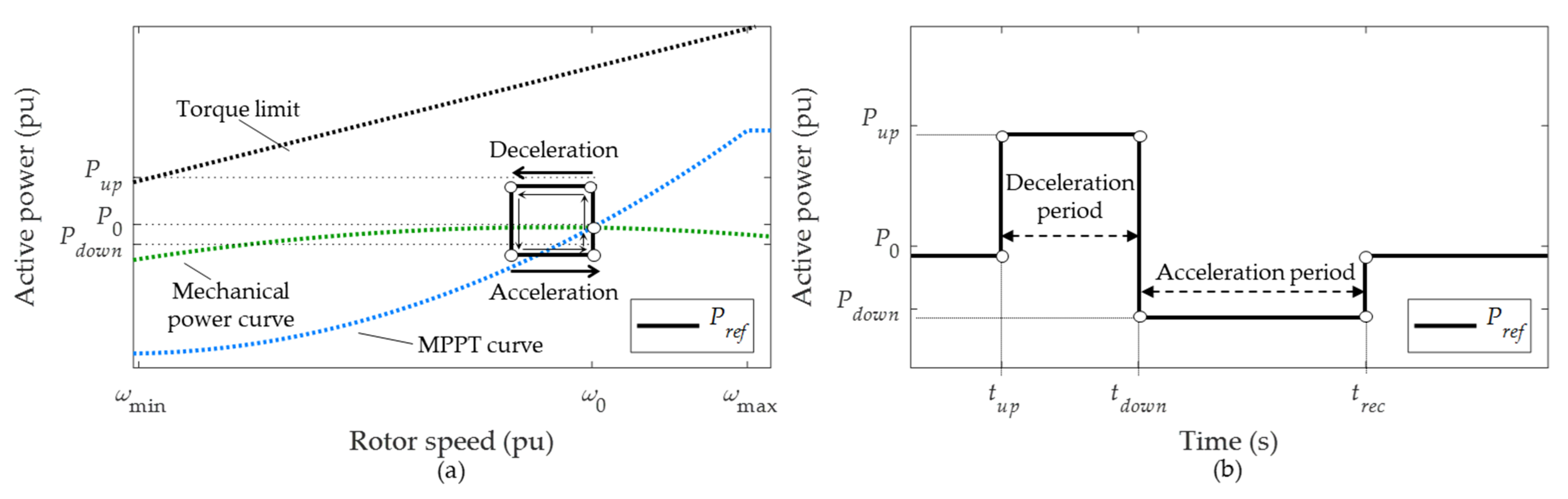
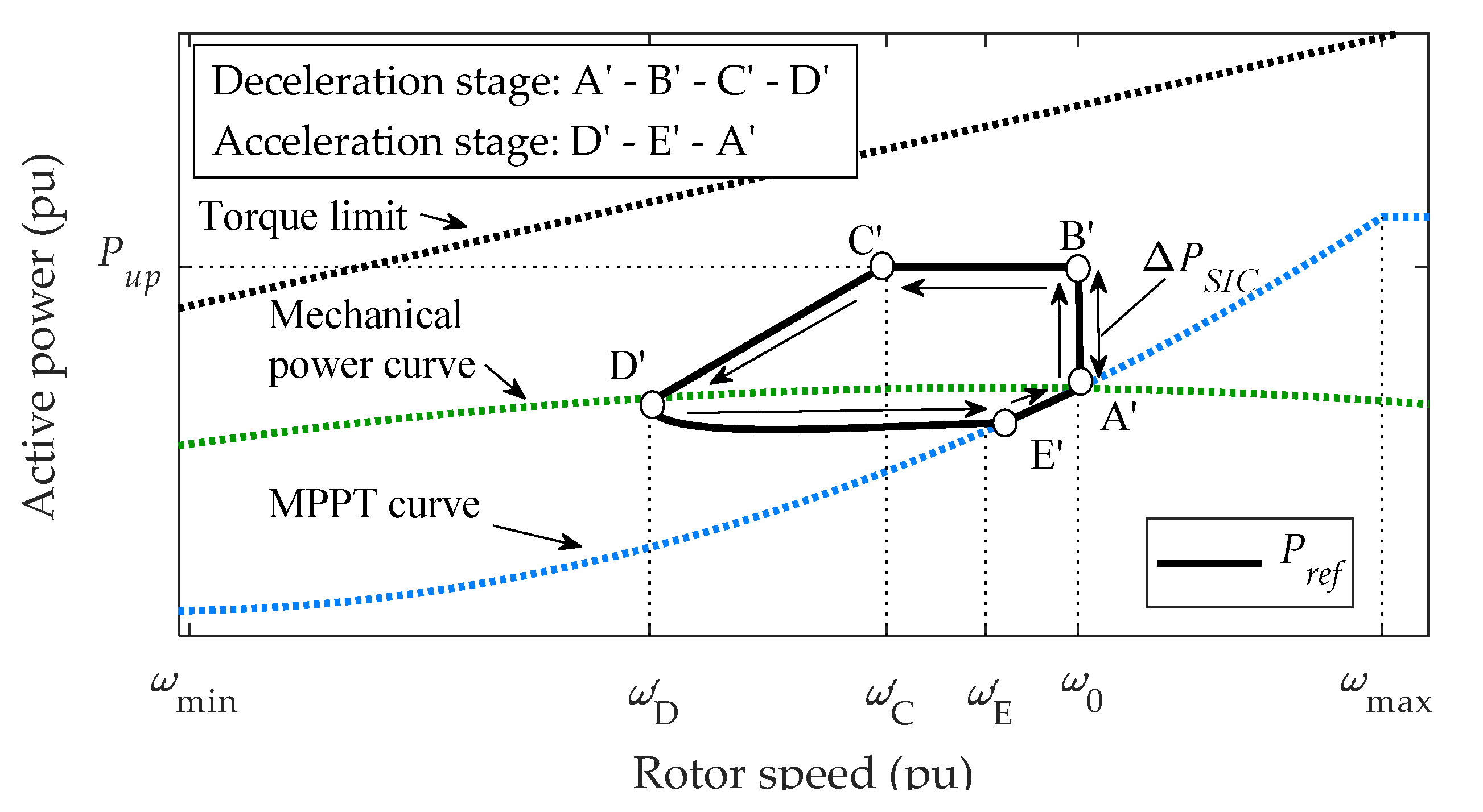
As mentioned previously, there are FBIC and SIC methods for the WPP VIC method. The WPPs operated by the FBIC method provide the IR based on the frequency deviation and rate of change of frequency change (RoCoF) [13]. On the other hand, WPPs operated by the SIC method provide the IR independently from the frequency but based on the deceleration and acceleration stage [11], as shown in Figure 4. As Pref is increased from P0 to Pup by the SIC method, the right term of the swing equation of Equation (5) becomes negative. As a result, the rotor speed starts to decelerate right after Pref is increased from P0 to Pup. Then, to recover the rotor speed to ω0, the SIC method decreases the Pref from Pup to Pdown.
After the SIC method has been developed in [11], many studies have improved this SIC method to provide active power more effectively and improve the frequency stability [18,19]. While the SIC method in [11] increases power by 0.1 pu without considering the WPPL or wind condition, the SIC method recently developed in [19] increases the power regarding the prevention of secondary frequency dip while providing effective support for frequency nadir. Therefore, this SIC method increases the power by ΔPSIC as
where PT-lim(ω0) is the power at ω0 based on the torque limit, and m is an index depending on the WPPLs. Note that m is decreased as WPPL increases. This is because if each WPP provides the same amount of ΔPSIC in high WPPL, the power decrement after frequency nadir arrestment (point C’ in Figure 5) also becomes high. As a result, this may cause other conventional SGs with a slow frequency response speed to compensate, causing a secondary frequency dip. Therefore, ΔPSIC is decreased by reducing m in Equation (6) when WPPL increases. After frequency nadir is arrested, Pref is decreased from point C’ to D’, and enters the acceleration stage to recover the rotor speed to ω0.
3. Proposed Cooperative Control Framework
As the WPPL increases, power curtailment becomes essential to balance the power supply and demand. However, as mentioned previously, the increment on required power curtailment can cause significant ΔPdec, resulting in a severe frequency dip before reaching its nominal value. As shown in Figure 6, when WPPs are switched from the MPPT control method to the curtailed control method, in order to maintain the power balance and restore the frequency from f0 to nominal frequency (fnorm), the output power of the WPPs is instantly decreased further by ΔPdec. As a result, the frequency falls significantly before reaching fnorm, and this problem becomes severe as WPPL is increased. Moreover, suppose the frequency falls beyond the dead-band of the governor before reaching fnorm. In that case, it will activate the governor response from SGs to compensate for the power loss using the primary frequency reserve.
In order to solve this frequency dip problem, the proposed cooperative control framework determines the overall WPPs operation in the SIC and curtailed control methods to provide the required power requirement while improving the frequency dip. The main reason for the frequency dip occurrence during the power curtailment is the sudden significant output power decrement from WPPs. To solve this problem, the proposed framework operates some WPPs by the SIC method during the power curtailment. Therefore, they instantly increase the power by providing IR for a short period to compensate for the power decrement, and, after providing IR, they decrease the power back to its initial value (see Figure 5). As a result, the excessive power decrement of ΔPdec caused by the curtailed control method may be compensated while improving the frequency dip without disturbing the frequency recovery to fnorm.
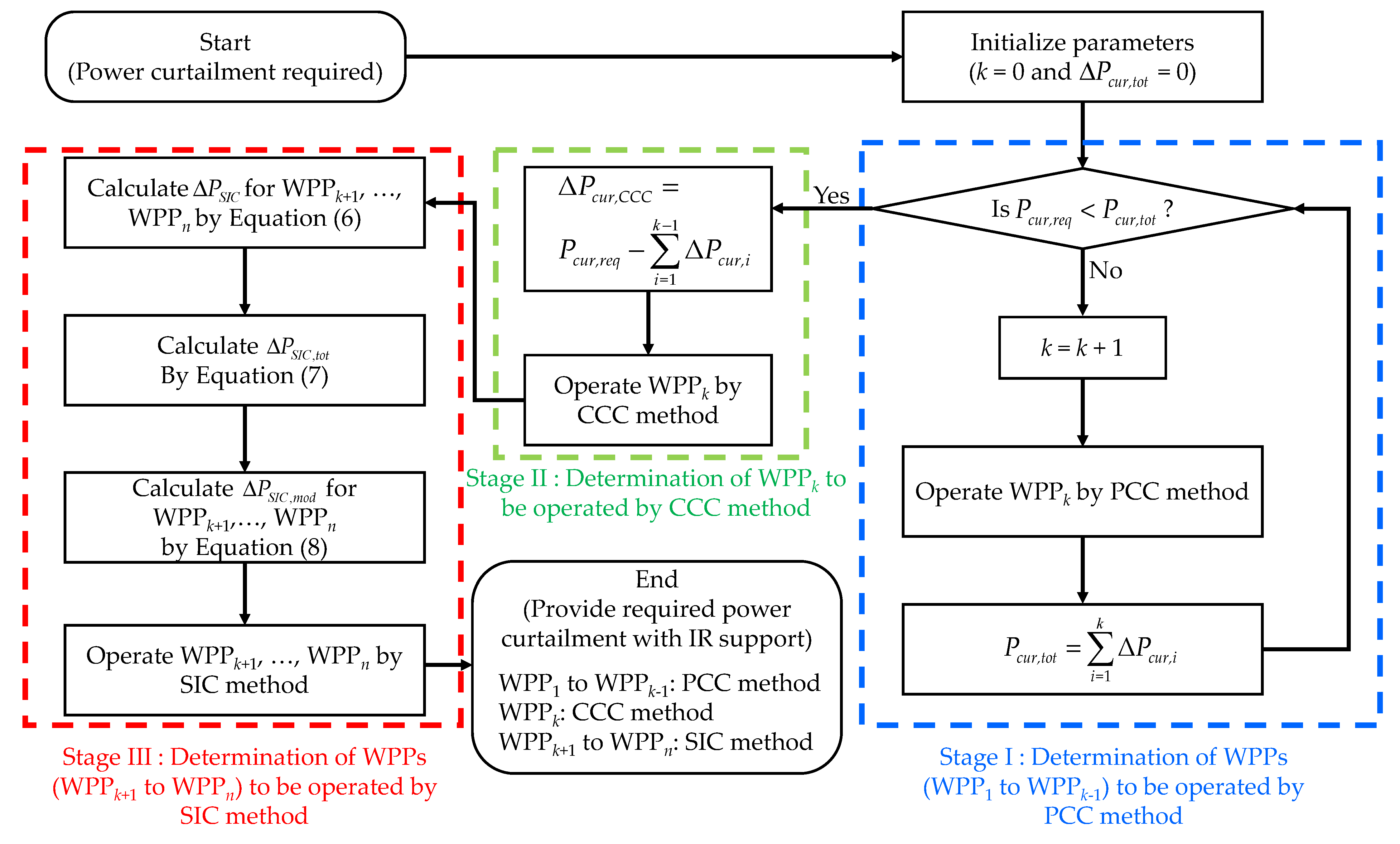
The overall procedure to implement the proposed cooperative control framework is shown in Figure 7, and the detailed operations are explained below. Note that the SIC method in [19] is used for the VIC method, and CCC and PCC methods are considered for curtailed control methods in the proposed framework.
- Stage I—As power curtailment is required to maintain the power balance, parameters including the iteration number (k) and the total sum of the power curtailment from WPPs (Pcur,tot) are initialized. Then, the proposed coordination control framework begins. In this stage, the framework firstly assigns the WPPs to be operated by the PCC method to provide the required power curtailment (Pcur,req). Considering the technical operation limit [10], αcur is assumed to be 5%. Note that WPPs are assigned to be operated by this method until Pcur,tot becomes higher than Pcur,req.
- Stage II—As Pcur,tot becomes larger than Pcur,req in the previous stage, the system operator needs to decrease the Pcur,tot to curtail the exact amount of Pcur,req. If WPPs curtail more than Pcur,req, the frequency will not recover to fnorm but will converge to a lower value. Therefore WPPk is operated by the CCC method to curtail the exact amount of insufficient power curtailment (ΔPcur,CCC). As a result, while WPP1 to WPPk−1 are operated by the PCC method with αcur of 5%, WPPk is operated by the CCC method with ΔPcur,CCC to curtail the exact amount of Pcur,req.
- Stage III—After determining the WPPs to be operated by the curtailment control method (PCC and CCC methods), the other WPPs are determined to be operated by the SIC method to compensate for the power decrement caused by other WPPs operated by PCC and CCC methods. To do so, the total available IR for WPPk+1 to WPPn (ΔPSIC,tot) is calculated as
Figure 7.
Implementation of the proposed cooperative control framework.

However, if ΔPSIC,tot is larger than the required power curtailment, it will cause another power imbalance. Therefore, ΔPSIC for each WPP is modified considering the required power curtailment as
Therefore, the other WPPs (WPPk+1 to WPPn) provide IR to compensate for the power decrement without causing a power imbalance.
In summary, when a large amount of power is curtailed from WPPs, excessive power decrement instantly occurs during the power curtailment, which causes a significant frequency drop before the frequency recovers to fnorm. To solve this problem without disturbing the power balance, the proposed cooperative control framework operates WPPs partially by the SIC method to provide instant frequency support. In particular, the curtailed control method is first applied to WPPs with PCC methods, and then the CCC method is applied to provide the exact power curtailment of Pcur,req. Moreover, the other WPPs that are not operated by the curtailed control method are operated by the SIC method considering the Pcur,req to compensate for the excessive power decrement.
4. Simulation Results
To verify the effectiveness of the proposed cooperative control framework, several case studies are carried out on the practical South Korea electric power system using the DIgSILENT PowerFactory® software to provide an effective solution for power curtailment.
4.1. Characteristics of South Korea Electric Power System
In the practical South Korea electric power system, there are about 400 SGs with a power capacity of 145 GW. Moreover, the load demand and power supply for one day during winter in 2020 used in the simulation are about 82.4 and 83.9 GW, respectively. Furthermore, the load demand and the power generation considering the types of SGs are given in Table 1 according to the provinces with six areas. Therefore, the South Korea electric power system has regional characteristics. As given in Table 1, area 1, which includes the capital Seoul of South Korea, has the largest load demand. However, it is observed that the power generation in area 1 is much lower than the load demand. Therefore, power is transmitted from the other areas through a high-voltage transmission line, such as 345 and 765 kV transmission lines. Moreover, the types of SGs and their roles are different among areas. For example, nuclear power plants, which take charge of base load power plants, are primarily located in areas 5 and 6. On the other hand, the coal power plants, which take charge of the load-following power plant, are primarily located in area 4. Lastly, the peaking power plants are practically located in areas 1 and 2.
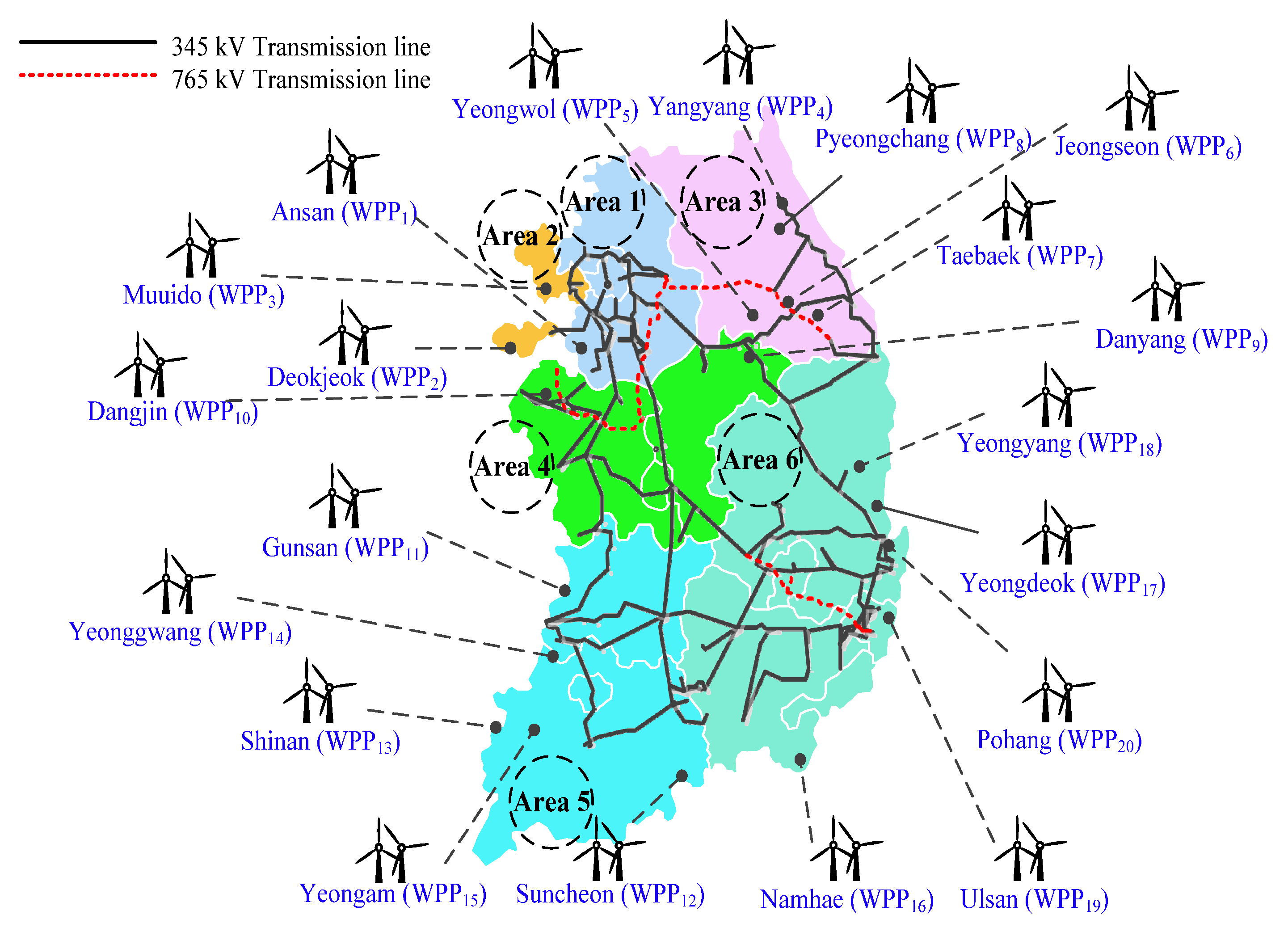
For wind resources, the currently installed capacity of WPPs is only about 1000 MW in the South Korea electric power system, which is much lower than conventional SGs. However, the South Korean government has planned to install 17.7 GW of WPPs by 2030. Therefore, in this paper, according to the South Korean government’s renewable energy policy and basic plan for long-term electricity supply and demand [20], 20 WPPs shown in Figure 8 are considered. Moreover, their capacity is given in Table 2, and the total capacity is about 10 GW. Furthermore, since the simulation environment of the South Korea electric power system is based on winter in early 2020, the wind speed scenario is based on January 2020 and February 2020, as given in Table 3.
4.2. Case 1—Required Power Curtailment of 606 MW
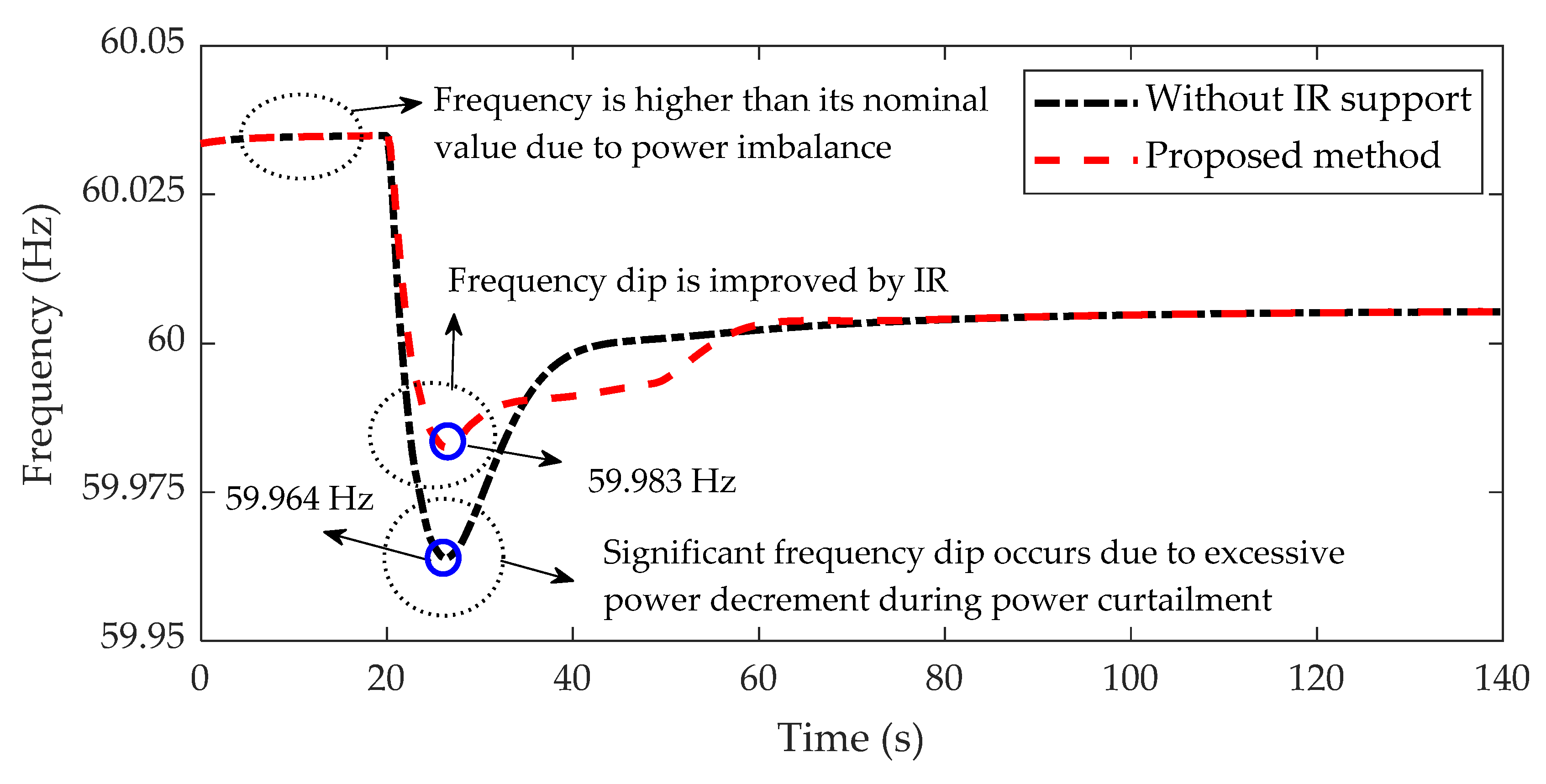
As shown in Figure 9, because of the power imbalance, the initial center of inertia (CoI) frequency [21] is 60.035 Hz, which is higher than fnorm of 60 Hz. Note that the CoI frequency, fCOI, is calculated as
where HSG,j and SSG,j are the inertia constant and capacity of the j-th SGs, and fSG,j is the measured frequency of the bus that is connected to the j-th SGs. However, there are many SGs and buses in a practical large-scale power system, making it impossible to measure the frequency of every bus to obtain fCOI. Therefore, the frequency of SGs with the largest capacity in each area is selected and measured to obtain fCOI.
In case 1, due to wind conditions based on January, 606 MW is required for power curtailment to balance the power supply and demand. In order to curtail 606 MW, WPP operations are determined using the proposed cooperative control framework shown in Figure 7. As a result, WPPs (WPP1 to WPP9) are operated by the PCC method with an αcur of 5%, and WPP10 is operated by the CCC method with a constant power curtailment of 69.8 MW. On the other hand, when power curtailment occurs from WPPs (WPP1 to WPP10), other WPPs (WPP11 to WPP20) are operated by the SIC method. Note that, since ΔPSIC,tot (210 MW) is much lower than Pcur,req (606 MW), ΔPSIC for WPPs (WPP11 to WPP20) are not modified by Equation (8).
As shown in Figure 10, WPPs (WPP1 to WPP10) determined to be operated by the curtailed control method are curtailed at 20 s. As a result, the imbalance of power supply and demand is solved, and fCOI starts to decrease from 60.04 Hz to fnorm. However, while 606 MW is curtailed from WPPs, an additional 230 MW of excessive power decrement occurs in the power system. Therefore, as shown in Figure 9, fCOI drops significantly to 59.964 Hz before recovering to 60 Hz. To solve this problem, the proposed cooperative control framework operates WPP11 to WPP20 by the SIC method. Thus, they provide an IR of 210 MW at 20 s to compensate for the power decrement. As a result, it clearly shows that the fCOI dip is significantly improved to 59.983 Hz (see the dashed red line in Figure 9). Table 4 summarizes the operation of 20 WPPs during the power curtailment.
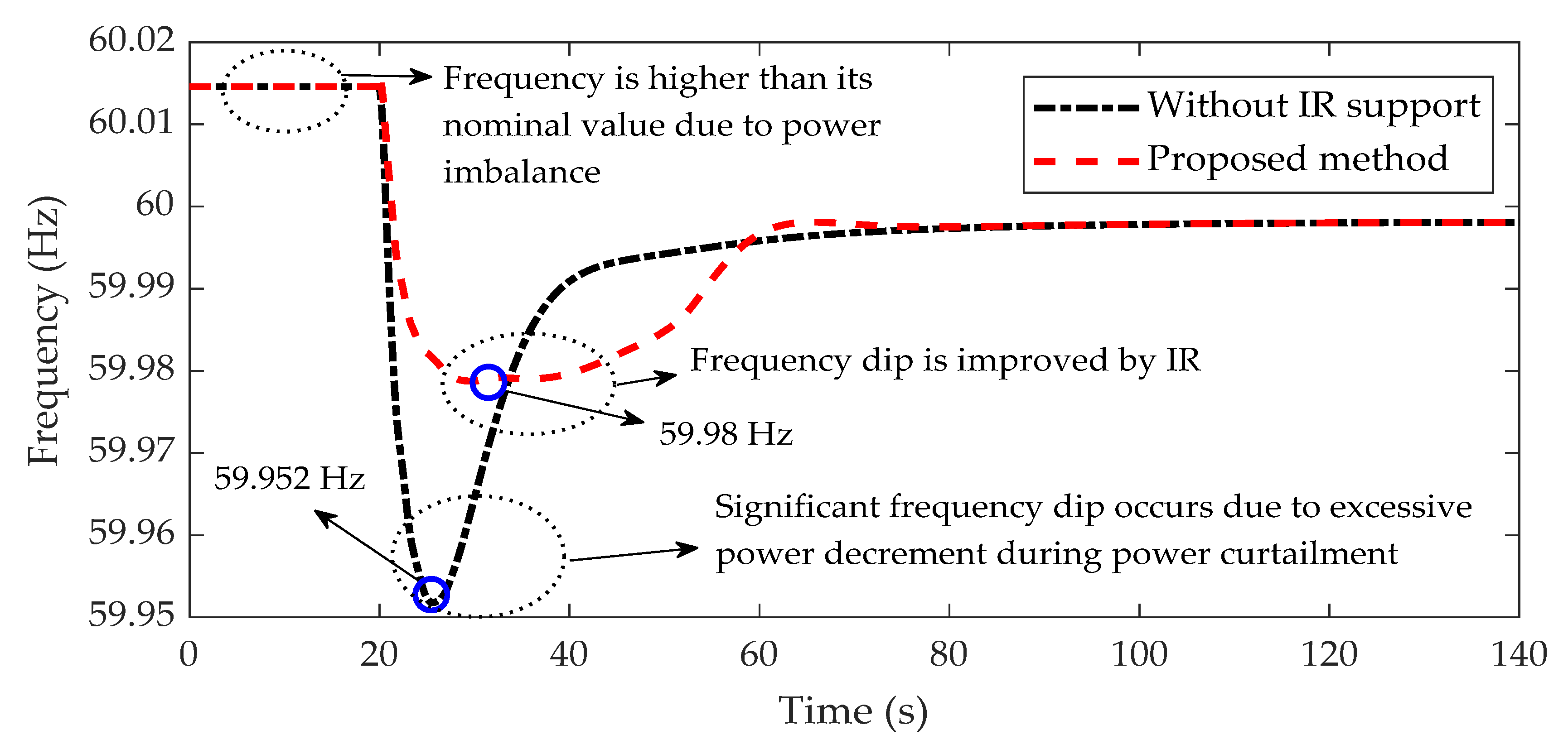
4.3. Case 2—Required Power Curtailment of 337 MW
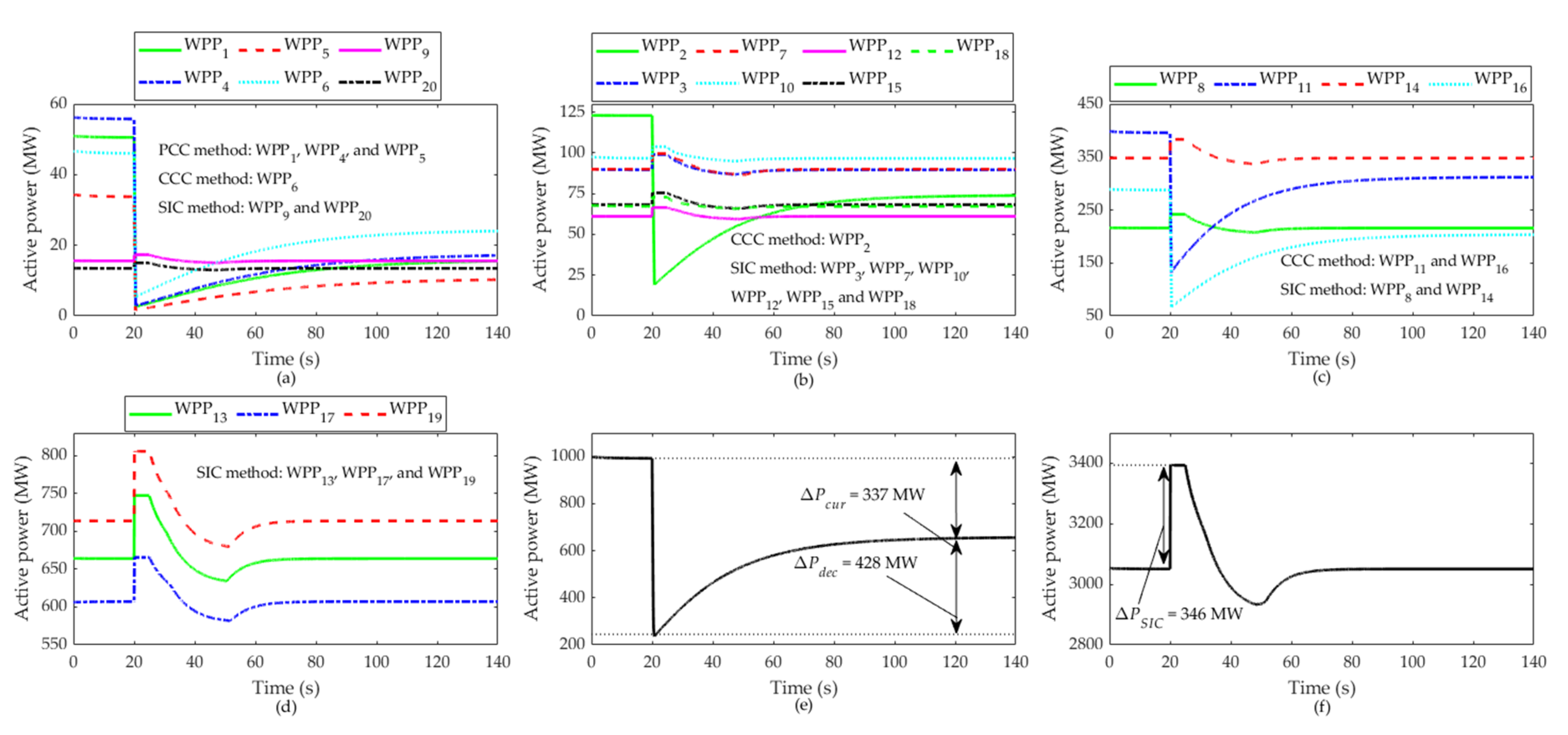
In case 2, the imbalance between power supply and demand raises the fCOI to 60.015 Hz. Note that the fCOI exceeds fnorm by a smaller amount than that of case 1. This is because the total power generated from the overall WPPs is smaller than case 1 due to the wind conditions. In order to balance the power supply and demand, 337 MW is required for power curtailment. To solve this problem, the proposed cooperative control framework is applied to determine the 20 WPPs operation. In general, the power system is operated by each area rather than operating the entire system as one large area. Therefore, the proposed framework is applied in each area to determine the operation of WPPs for this case study. However, since there are fewer WPPs in areas 1, 2, and 4, the operation of WPPs in these areas is considered simultaneously. Thus, in order to curtail 337 MW, each area is curtailed by 84.3 MW. As a result, the framework determines WPPs (WPP1, WPP4, and WPP5) to be operated by the curtailed control method (PCC method), which provides power curtailment. Moreover, WPP2, WPP6, WPP11, and WPP16 are operated by the CCC method to balance the power supply and demand precisely for each area. Note that WPPs are not operated by the PCC method for areas 5 and 6 since WPPs (WPP11 and WPP16) operated by the CCC method can provide the required curtailment for each area. Finally, the remaining WPPs are operated by the SIC method to provide IR and compensate for the instant power decrement during power curtailment.
As shown in Figure 11, fCOI is over 60 Hz during 0 s to 20 s due to a power imbalance of 337 MW. After determining the WPPs operation using the proposed cooperative control framework, WPPs are curtailed at 20 s to balance the power supply and demand, making fCOI recover to fnorm, which is 60 Hz. However, as shown in Figure 12e, an additional power decrement of 428 MW occurs during power curtailment. As a result, a frequency dip occurs, making fCOI decrease to 59.952 Hz before reaching 60 Hz. In order to solve this problem, the proposed coordination control framework additionally operates WPPs (WPP3, WPP7, WPP8, WPP9, WPP10, WPP12, WPP13, WPP14, WPP15, WPP17, WPP18, WPP19, and WPP20) by the SIC method as soon as power curtailment occurs from other WPPs. As a result, the frequency dip is increased to 59.98 Hz. Table 5 summarizes the operation of 20 WPPs during the power curtailment.
In summary, it is clearly shown from cases 1 and 2 that a large amount of power curtailment causes instant power decrement during a switching process from the MPPT control method to the curtailed control method. Moreover, this causes a significant frequency dip before reaching fnorm. To solve this problem, the proposed cooperative control framework determines WPP operation in three control methods, which are the PCC, CCC, and SIC methods. Therefore, the proposed framework operates WPPs that could provide required power curtailment for power balance while also providing IR to compensate for the instant power decrement. The results show that frequency dip during the power curtailment is significantly improved using the solution by the proposed framework.
5. Conclusions
This paper proposed the new cooperative control framework between the curtailed control and virtual inertial control (VIC) methods to minimize the instant power decrement during the power curtailment and improve the frequency dip. To do so, this paper first analyzed the power loss that occurs in the process of switching from the maximum power point tracking control method to the curtailed control method, which caused a severe impact on frequency stability during the frequency recovery. In order to solve this problem, the proposed cooperative control framework determined the WPP operation in the proportional curtailment control (PCC) and constant curtailment control (CCC) methods to provide the required power curtailment. Then, it operated the rest of the WPPs by the stepwise inertial control (SIC) method to provide an inertial response with the consideration of the power balance.
The effectiveness of the proposed coordination framework was verified with several case studies on the practical South Korea electric power system. The results show that the proposed coordination framework successfully determined WPP operation in the PCC, CCC, and SIC methods to provide the required power curtailment and compensate for the excessive power decrement. Therefore, it is expected that the proposed framework would provide a promising solution on power curtailment and enable the high penetration of WPPs to the power system.
Author Contributions
The research was conducted in collaboration with all authors. S.L. wrote the paper; S.L. performed the simulations; S.-M.B. and J.-W.P. supervised the paper. All authors have read and agreed to the published version of the manuscript.
Funding
This work was supported in part by the National Research Foundation of Korea (NRF) (grant number: 2020R1A3B2079407), the Ministry of Science and ICT (MSIT), Korea, and in part by Basic Science Research Program through the NRF funded by the Ministry of Education (grant number: 2020R1I1A3074996).
Conflicts of Interest
The authors declare no conflict of interest.
References
- Renewable Energy Statistics 2021. Available online: https://www.irena.org/publications/2021/Aug/Renewable-energy-statistics-2021 (accessed on 5 October 2021).
- Eto, J.H.; Berkeley, L.; Undrill, J.; Mackin, P.; Daschmans, R.; Williams, B.; Haney, B.; Hunt, R.; Ellis, J.; Illian, H.; et al. Use of Frequency Response Metrics to Assess the Planning and Operating Requirements for Reliable Integration of Variable Renewable Generation; Lawrence Berkeley National Laboratory (LBNL): Berkeley, CA, USA, 2010. [Google Scholar]
- Kayikçi, M.; Milanovic, J.V. Dynamic Contribution of DFIG-Based Wind Plants to System Frequency Disturbances. IEEE Trans. Power Syst. 2009, 24, 859–867. [Google Scholar] [CrossRef]
- Vorobev, P.; Greenwood, D.M.; Bell, J.H.; Bialek, J.W.; Taylor, P.C.; Turitsyn, K. Deadbands, Droop, and Inertia Impact on Power System Frequency Distribution. IEEE Trans. Power Syst. 2019, 34, 3098–3108. [Google Scholar] [CrossRef] [Green Version]
- Kumar, G.V.; Sarojini, R.K.; Palanisamy, K.; Padmanaban, S.; Holm-Nielsen, J.B. Large Scale Renewable Energy Integration: Issues and Solutions. Energies 2019, 12, 1996. [Google Scholar] [CrossRef] [Green Version]
- Oyekale, J.; Petrollese, M.; Tola, V.; Cau, G. Impacts of Renewable Energy Resources on Effectiveness of Grid-Integrated Systems: Succinct Review of Current Challenges and Potential Solution Strategies. Energies 2020, 13, 4856. [Google Scholar] [CrossRef]
- Nguyen, H.T.; Member, S.; Yang, G.; Member, S.; Hejde, A. Combination of Synchronous Condenser and Synthetic Inertia for Frequency Stability Enhancement in Low Inertia Systems. IEEE Trans. Sustain. 2019, 10, 997–1005. [Google Scholar] [CrossRef] [Green Version]
- Yan, X.; Sun, X. Inertia and Droop Frequency Control Strategy of Doubly-Fed Induction Generator Based on Rotor Kinetic Energy and Supercapacitor. Energies 2020, 13, 3697. [Google Scholar] [CrossRef]
- Yang, D.; Li, J.; Zhang, X.; Hua, L. Frequency Support from a Variable-Speed Wind Turbine Generator Using Different Variable Droop Characteristics. Energies 2020, 13, 4477. [Google Scholar] [CrossRef]
- Cañas-Carretón, M.; Carrión, M. Generation Capacity Expansion Considering Reserve Provision by Wind Power Units. IEEE Trans. Power Syst. 2020, 35, 4564–4573. [Google Scholar] [CrossRef]
- Ullah, N.R.; Thiringer, T.; Karlsson, D. Temporary Primary Frequency Control Support by Variable Speed Wind Turbines—Potential and Applications. IEEE Trans. Power Syst. 2008, 23, 601–612. [Google Scholar] [CrossRef]
- Kang, M.; Muljadi, E.; Hur, K.; Kang, Y.C. Stable Adaptive Inertial Control of a Doubly-Fed Induction Generator. IEEE Trans. Smart Grid 2016, 7, 2971–2979. [Google Scholar] [CrossRef]
- Hu, J.; Sun, L.; Yuan, X.; Wang, S.; Chi, Y. Modeling of Type 3 Wind Turbines with df/dt Inertia Control for System Frequency Response Study. IEEE Trans. Power Syst. 2017, 32, 2799–2809. [Google Scholar] [CrossRef]
- Wang, Y.; Bayem, H.; Giralt-devant, M.; Silva, V.; Guillaud, X.; Francois, B. Methods for Assessing Available Wind Primary Power Reserve. IEEE Trans. Sustain. Energy 2015, 6, 272–280. [Google Scholar] [CrossRef]
- DIgSILENT. DIgSILENT PowerFactory 2018 User Manual; DIgSILENT: Gomaringen, Germany, 2018. [Google Scholar]
- Deng, J.; Wang, J.; Li, S.; Zhang, H.; Peng, S.; Wang, T. Adaptive Damping Design of PMSG Integrated Power System with Virtual Synchronous Generator Control. Energies 2020, 13, 2037. [Google Scholar] [CrossRef] [Green Version]
- Zhang, X.L.; Huang, C.; Hao, S.P.; Chen, F.; Zhai, J.J. An Improved Adaptive-Torque-Gain MPPT Control for Direct-Driven PMSG Wind Turbines Considering Wind Farm Turbulences. Energies 2016, 9, 977. [Google Scholar] [CrossRef] [Green Version]
- Kang, M.; Kim, K.; Muljadi, E.; Park, J.W.; Kang, Y.C. Frequency Control Support of a Doubly-Fed Induction Generator Based on the Torque Limit. IEEE Trans. Power Syst. 2016, 31, 4575–4583. [Google Scholar] [CrossRef]
- Yang, D.; Kim, J.; Kang, Y.C.; Muljadi, E.; Zhang, N.; Hong, J.; Song, S.; Zheng, T. Temporary Frequency Support of a DFIG for High Wind Power Penetration. IEEE Trans. Power Syst. 2018, 33, 3428–3437. [Google Scholar] [CrossRef]
- Nam, H. Impact of Nuclear Phase-Out Policy and Energy Balance in 2029 Based on the 8th Basic Plan for Long-Term Electricity Supply and Demand in South Korea. Renew. Sustain. Energy Rev. 2020, 122, 109723. [Google Scholar] [CrossRef]
- Mujcinagic, A.; Kusljugic, M.; Nukic, E. Wind Inertial Response Based on the Center of Inertia Frequency of a Control Area. Energies 2020, 13, 6177. [Google Scholar] [CrossRef]
Figure 1.
Classification of WPP control methods.

Figure 2.
MPPT curve and operational characteristics of WPPs.

Figure 3.
Operational characteristics of the curtailed control method for WPP.

Figure 4.
Operational characteristics of the conventional SIC method. (a) Active power and rotor speed plane. (b) Active power and time plane.
Figure 4.
Operational characteristics of the conventional SIC method. (a) Active power and rotor speed plane. (b) Active power and time plane.

Figure 5.
Operational characteristics of the recent SIC method.

Figure 6.
Frequency dip occurrence due to excessive power decrement during power curtailment. (a) Output power of WPPs operated in curtailed control method. (b) Frequency response when power curtailment occurs.
Figure 6.
Frequency dip occurrence due to excessive power decrement during power curtailment. (a) Output power of WPPs operated in curtailed control method. (b) Frequency response when power curtailment occurs.

Figure 8.
South Korea electric power system with 20 WPPs.

Figure 9.
Results of center of inertia frequency for case 1.

Figure 10.
Results of output power from WPPs for case 1. (a) WPP1, WPP5, WPP6, WPP9, WPP12, WPP15, WPP20. (b) WPP2, WPP3, WPP4, WPP7, WPP8, WPP10, WPP18. (c) WPP11, WPP14, WPP16. (d) WPP13, WPP17, WPP19. (e) Total output power of WPPs operated by curtailed control method. (f) Total output power of WPPs operated by SIC method.

Figure 11.
Results of center of inertia frequency for case 2.

Figure 12.
Results of output power from WPPs for case 2. (a) WPP1, WPP4, WPP5, WPP6, WPP9, WPP20. (b) WPP2, WPP3, WPP7, WPP10, WPP12, WPP15, WPP18. (c) WPP8, WPP11, WPP14, WPP16. (d) WPP13, WPP17, WPP19. (e) Total output power of WPPs operated by curtailed control method. (f) Total output power of WPPs operated by SIC method.


Table 1.
Load demand and power generation according to areas in winter of early 2020.
| Area No. | Area Name | Load Demand (MW) | Power Generation | ||||
|---|---|---|---|---|---|---|---|
| Nuclear (MW) | Coal (MW) | Combined Cycle (MW) | Others (MW) | Total (MW) | |||
| 1 | Seoul/Gyeonggi | 26,115 | 0 | 0 | 9717 | 5214 | 14,931 |
| 2 | Incheon | 7056 | 0 | 4826 | 4697 | 0 | 9523 |
| 3 | Gangwon | 2615 | 0 | 2820 | 0 | 1204 | 4024 |
| 4 | Chungcheong | 14,096 | 0 | 16,886 | 1835 | 359 | 19,080 |
| 5 | Jeolla | 8642 | 5201 | 1111 | 3637 | 715 | 10,664 |
| 6 | Gyeongsang | 23,871 | 11,791 | 6786 | 3902 | 3242 | 25,721 |
Table 2.
Hosting capacity of 20 WPPs.
| Capacity (MW) | |||||||||
|---|---|---|---|---|---|---|---|---|---|
| WPP1 | WPP2 | WPP3 | WPP4 | WPP5 | WPP6 | WPP7 | WPP8 | WPP9 | WPP10 |
| 200.1 | 299 | 299 | 220.8 | 167.9 | 218.5 | 170.2 | 637.1 | 46 | 400.2 |
| WPP11 | WPP12 | WPP13 | WPP14 | WPP15 | WPP16 | WPP17 | WPP18 | WPP19 | WPP20 |
| 1499.6 | 119.6 | 1499.6 | 878.6 | 154.1 | 1000.5 | 1000.5 | 278.3 | 1499.6 | 41.4 |
Table 3.
Wind speed of 20 WPPs for all cases.
| Wind Speed (m/s) | ||||||||||
|---|---|---|---|---|---|---|---|---|---|---|
| WPP1 | WPP2 | WPP3 | WPP4 | WPP5 | WPP6 | WPP7 | WPP8 | WPP9 | WPP10 | |
| Case 1 (January) | 6.5 | 7.3 | 6.8 | 7.7 | 6.4 | 6.7 | 8.7 | 8.2 | 8.7 | 6.8 |
| Case 2 (February) | 6.8 | 8 | 7.2 | 6.8 | 6.3 | 6.4 | 8.7 | 7.5 | 7.5 | 6.7 |
| WPP11 | WPP12 | WPP13 | WPP14 | WPP15 | WPP16 | WPP17 | WPP18 | WPP19 | WPP20 | |
| Case 1 (January) | 7.4 | 8 | 8.5 | 7.4 | 7.5 | 8.1 | 9 | 7.6 | 8.8 | 7.4 |
| Case 2 (February) | 6.9 | 8.6 | 8.2 | 7.9 | 8.2 | 7.1 | 9.1 | 6.7 | 8.4 | 7.4 |
Table 4.
Summary of WPPs operation and numerical results for case 1.
| WPP No. | Control Method | P0 (MW) | ΔPcur (MW) | ΔPdec (MW) | ΔPSIC (MW) |
|---|---|---|---|---|---|
| WPP1 | PCC | 44.2 | 30.6 | 11.5 | - |
| WPP2 | PCC | 93.4 | 64.3 | 24.4 | - |
| WPP3 | PCC | 75.5 | 52.2 | 19.7 | - |
| WPP4 | PCC | 81 | 55.7 | 21.2 | - |
| WPP5 | PCC | 35.4 | 24.5 | 9.2 | - |
| WPP6 | PCC | 52.8 | 36.5 | 13.7 | - |
| WPP7 | PCC | 90 | 61.7 | 23.6 | - |
| WPP8 | PCC | 282.1 | 193.6 | 73.9 | - |
| WPP9 | PCC | 24.3 | 16.7 | 6.4 | - |
| WPP10 | CCC | 101.1 | 69.8 | 26.4 | - |
| WPP11 | SIC | 488.1 | - | - | 30.8 |
| WPP12 | SIC | 49.2 | - | - | 3 |
| WPP13 | SIC | 739.6 | - | - | 43.9 |
| WPP14 | SIC | 286 | - | - | 17.5 |
| WPP15 | SIC | 52.2 | - | - | 3.5 |
| WPP16 | SIC | 427 | - | - | 28.4 |
| WPP17 | SIC | 587.4 | - | - | 29.9 |
| WPP18 | SIC | 98.1 | - | - | 5.1 |
| WPP19 | SIC | 820.7 | - | - | 47.4 |
| WPP20 | SIC | 13.5 | - | - | 0.9 |
| Total | - | 4441.6 | 605.6 | 230 | 210.4 |
Table 5.
Summary of WPPs operation and numerical results for case 2.
| WPP No. | Control Method | P0 (MW) | ΔPcur (MW) | ΔPdec (MW) | ΔPSIC (MW) |
|---|---|---|---|---|---|
| WPP1 | PCC | 50.6 | 35.1 | 13.2 | - |
| WPP2 | CCC | 122.9 | 49.2 | 54.9 | - |
| WPP3 | SIC | 89.6 | - | - | 9.5 |
| WPP4 | PCC | 55.8 | 38.7 | 14.6 | - |
| WPP5 | PCC | 33.8 | 23.7 | 8.8 | - |
| WPP6 | CCC | 46.0 | 21.9 | 18.9 | - |
| WPP7 | SIC | 90.0 | - | - | 9.7 |
| WPP8 | SIC | 215.9 | - | - | 26.0 |
| WPP9 | SIC | 15.6 | - | - | 1.7 |
| WPP10 | SIC | 96.7 | - | - | 7.3 |
| WPP11 | CCC | 395.8 | 84.3 | 180.3 | - |
| WPP12 | SIC | 61.1 | - | - | 5.5 |
| WPP13 | SIC | 664.0 | - | - | 84.4 |
| WPP14 | SIC | 347.9 | - | - | 35.8 |
| WPP15 | SIC | 68.2 | - | - | 7.4 |
| WPP16 | CCC | 287.7 | 84.3 | 137.2 | - |
| WPP17 | SIC | 607.2 | - | - | 58.3 |
| WPP18 | SIC | 67.3 | - | - | 5.8 |
| WPP19 | SIC | 713.8 | - | - | 92.9 |
| WPP20 | SIC | 13.5 | - | - | 1.5 |
| Total | - | 4043.3 | 337.2 | 427.9 | 345.8 |
Publisher’s Note: MDPI stays neutral with regard to jurisdictional claims in published maps and institutional affiliations. |
© 2022 by the authors. Licensee MDPI, Basel, Switzerland. This article is an open access article distributed under the terms and conditions of the Creative Commons Attribution (CC BY) license (https://creativecommons.org/licenses/by/4.0/).
Share and Cite
MDPI and ACS Style
Lim, S.; Baek, S.-M.; Park, J.-W. Selection of Inertial and Power Curtailment Control Methods for Wind Power Plants to Enhance Frequency Stability. Energies 2022, 15, 2630. https://0-doi-org.brum.beds.ac.uk/10.3390/en15072630
AMA Style
Lim S, Baek S-M, Park J-W. Selection of Inertial and Power Curtailment Control Methods for Wind Power Plants to Enhance Frequency Stability. Energies. 2022; 15(7):2630. https://0-doi-org.brum.beds.ac.uk/10.3390/en15072630
Chicago/Turabian StyleLim, SungHoon, Seung-Mook Baek, and Jung-Wook Park. 2022. "Selection of Inertial and Power Curtailment Control Methods for Wind Power Plants to Enhance Frequency Stability" Energies 15, no. 7: 2630. https://0-doi-org.brum.beds.ac.uk/10.3390/en15072630
Note that from the first issue of 2016, this journal uses article numbers instead of page numbers. See further details here.