Article

Hybrid Solid Oxide Fuel Cell/Gas Turbine Model Development for Electric Aviation

1
Department of Chemical Engineering, Institute for Materials Research and Innovation, University of Louisiana at Lafayette, Lafayette, LA 70504, USA
2
Department of Mechanical Engineering, Institute for Materials Research and Innovation, University of Louisiana at Lafayette, Lafayette, LA 70504, USA
3
Nexceris LLC, 404 Enterprise Dr, Lewis Center, OH 43035, USA
*
Author to whom correspondence should be addressed.
Submission received: 7 February 2022 / Revised: 15 March 2022 / Accepted: 22 March 2022 / Published: 14 April 2022
(This article belongs to the Special Issue Solid Oxide Cells: Technology, Design and Applications)

Abstract

:
A thermodynamic model was developed and validated to analyze a high-performance solid oxide fuel cell and gas turbine (SOFC-GT) hybrid power system for electric aviation. This study used a process simulation software package (ProMax) to study the role of SOFC design and operation on the feasibility and performance of the hybrid system. Standard modules, including compressor, turbine, heat exchanger, reforming reactor, and combustor were used from the ProMax tool suite while a custom module was created to simulate the SOFC stack. The model used an SOFC test data set as an input. Additional SOFC stack performance effects, such as pressure, temperature, and utilization of air and fuel, were added from open source data. System performance predictors were SOFC specific power, fuel-to-electricity conversion efficiency, and hybrid system efficiency. Using these input data and predictors, a static thermodynamic performance model was created that can be modified for different system configurations and operating conditions. Prior to creating the final aircraft performance model, initial demonstration models were developed to validate output results. We used the NASA SOFC model as a benchmark, which was created with their Numerical Propulsion System Simulator (NPSS) software framework. Our output results matched within 1% of both the NASA model and open source SOFC performance data. With confidence gained in the accuracy of this model, a 1-MW SOFC-GT hybrid power system was constructed for an aircraft propulsion concept. Overall hybrid system efficiencies of > 75% FTE were observed during standard 36,000 feet cruise flight conditions.

1. Introduction

The development, implementation, and optimization of solid oxide fuel cell (SOFC) hybrid power systems has long been sought because of their inherent advantages including increased system efficiencies, higher combined power generation, fuel flexibility, and balance of plant integration opportunities. Two separate SOFC and turbomachinery power systems can be synergistically coupled to achieve the aforementioned advantages. One such hybrid aviation power system that has been researched since the 1990s is a solid oxide fuel cell combined with a gas turbine (SOFC-GT). SOFCs are electrochemical fuel cells with ionic conducting electrolyte layers that allows ionized oxygen to diffuse through from the cathode to the anode where the fuel is electrochemically oxidized to generate electricity. These fuel cells are known to operate between 500 and 1000 °C while displaying high efficiencies (>50%), low emissions, and good fuel flexibility [1]. Conversely, present gas turbines—including modern microturbines—used for power generation have relatively low efficiencies (30–50%), and generally require high turbine inlet temperatures to operate on the upper end of these limited efficiency ranges. Because SOFCs electrochemically oxidize fuel to generate electricity directly, they are not heat engines, and are thus not subject to Carnot cycle limitation. As a result, coupling an SOFC with a gas turbine leads to a cogeneration, hybrid power system with fuel to electricity efficiencies in the 65–75% range [1,2,3].
While gas turbines can be found in a wide array of both stationary and portable/mobile applications, conventional SOFCs have historically been limited to ground and stationary applications. This has mainly been due to their physical limitations (e.g., size and weight) and operational limitations (e.g., long startup times, consistent fuel feed, and low power density). In the last 10–20 years, however, industry-wide efforts to overcome these limitations have led to innovative technologies that have changed the SOFC landscape. Novel cell structures and materials are making higher power density cells possible, electrode/electrolyte doping is leading to cells with greater resistances to fuel sulfur poisoning, metal-supported cell backbones are increasing thermal stress tolerances and shortening startup times, and novel stack architectures are reducing weight and size while improving performance [4,5,6,7]. As these advancements have developed, SOFCs and SOFC-based hybrid power systems have been investigated and explored for portable/mobile applications in industries including the automotive, locomotive, and aerospace industries [2,3,4,5,8,9]. The interest and focus of this study are the SOFC-GT hybrid power systems for aerospace applications.
The aerospace industry is similarly facing many of the same environmental and market pressures that the automotive industry faces; airlines need to reduce emissions while improving system efficiency, fuel economy, and cost. In general, the commercial aircraft industry began looking at shifting into a more electric architecture (i.e., replacing many of the less efficient hydraulic and pneumatic systems with electric ones) in efforts to consume less fuel and reduce aircraft weight. This, however, translates to higher electrical power demands on the airplanes’ turbine engine driven generators in flight and the Auxiliary Power Units (APUs) on the ground. Although they are used in flight during emergency situations, APUs are typically used at the airport gate to satisfy electrical power needs when the main engines are shut down. The problem is that the Fuel-To-Electricity (FTE) conversion efficiencies of APUs are less than 20% while on the ground and main engine generators are only 30–40% efficient while in flight. As aircraft continue to move further towards future more electric architectures, the electrical demands will grow as well, leading to increased fuel consumption due to the low efficiencies, if not addressed [8,10,11]. Aircraft research and design teams have expressed interest in the SOFC-GT hybrid power system as a solution to many of the problems that the industry faces. SOFC-GT for APUs, and eventually for main propulsion power, have been proposed and explored because of their lower fuel consumption with overall system FTE efficiencies > 70%, reduced emissions, lower noise production, fuel flexibility, and long-term environmental sustainability [10,11].
For aircraft design teams to conduct these feasibility studies, SOFC-GT simulations/models need to be built. The challenge is to find suitable modeling methods and environments that produce accurate results for the fuel cell and all supporting equipment. Historically, SOFC modeling has been split into two different categories: micro/meso/macro-scale and system-level modeling. Table 1 provides readers with a guide to which modelling environments have been used and how ProMax, used in this work, compares or fits into the SOFC system-level modeling space.

1.1. Micro, Meso, and Macro SOFC Modeling

This modeling category aims to produce high-integrity, multidimensional, physical models including reaction kinetics (internal reforming and electrochemical oxidation), mass transfer and diffusion, electrochemistry (charge transfer, irreversible voltage loss analyses, etc.), thermal stress analyses, and non-steady state/non-isothermal operations. The most common modeling environments used in this category are MATLAB and COMSOL because of their computational power and ability to efficiently deploy a wide array of numerical methods. An overview by Bao et al. presented a comprehensive review of macro-SOFC modeling in which many of these topics are discussed in detail [24].

1.2. System-Level SOFC Modeling

This modelling effort aims to integrate SOFCs with supporting equipment for system or plant-level studies. SOFCs can be integrated with external reformers, turbomachinery, heat exchangers, pumps, and other required unit operations to report total system efficiencies, required fuel/air flowrates, fuel cell configuration and operating values, etc., for a given electrical power output requirement. Several different environments have been used for these types of modeling studies reported in literature. Researchers generally must choose between using established process simulation software packages (AspenPlus, CHEMCAD, etc.) and then building/retrofitting fuel cell models into them or using open-source/proprietary fuel cell models in platforms like Excel and then building in the process simulation capabilities around the fuel cell model.
The main objectives of this study are to: (1) build the first fuel cell-based hybrid power thermodynamic model in ProMax, proving this software package to be a viable and suitable option with numerous inherent advantages; (2) validate the model against real-world and experimental results/data as well as system-level models previously built in other environments; and (3) simulate a 1-MW SOFC-GT hybrid power system for electric aviation applications using current high-performing SOFC stack conditions and parameters. In carrying out these objectives, we will also prove that if the model is capable of predicting both previous and state-of-the-art SOFC data/system-level performances, then it stands to reason that future SOFC electrochemical parameters and performances could be used in this same model to predict system performances 20–30 years out. Key model outputs needed to compare these previous, current, and future hybrid power systems include total system efficiency, fuel and air flow requirements, SOFC thermal and electrochemical efficiencies, and various unit operating conditions including temperature and pressure. These parameters and more are reported for a static case at the commercial airline cruise altitude of 36,000 feet (10,973 m). The model will also be used to identify design bottlenecks and process challenges for future performance and sensitivity analyses.

2. Methodology

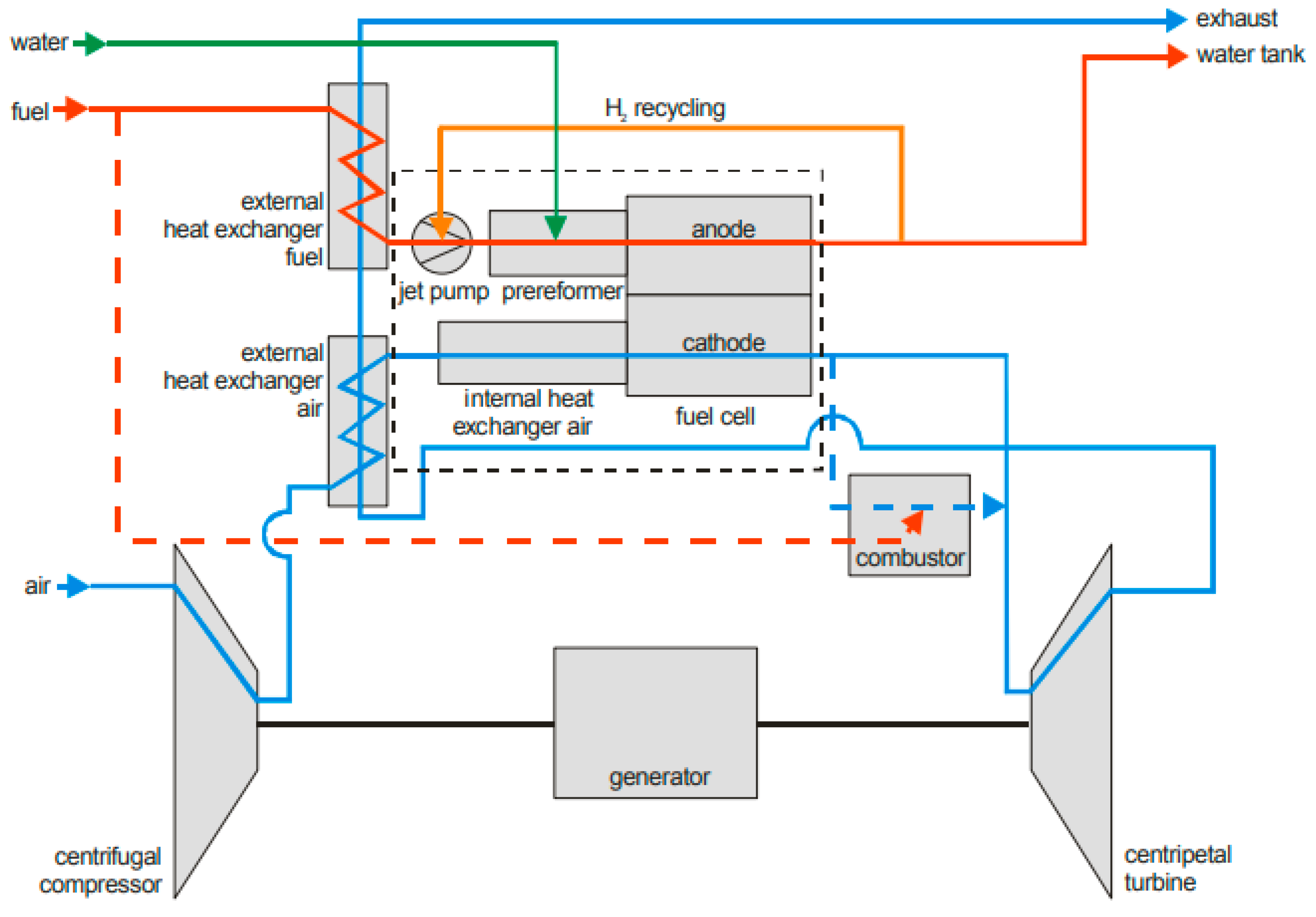
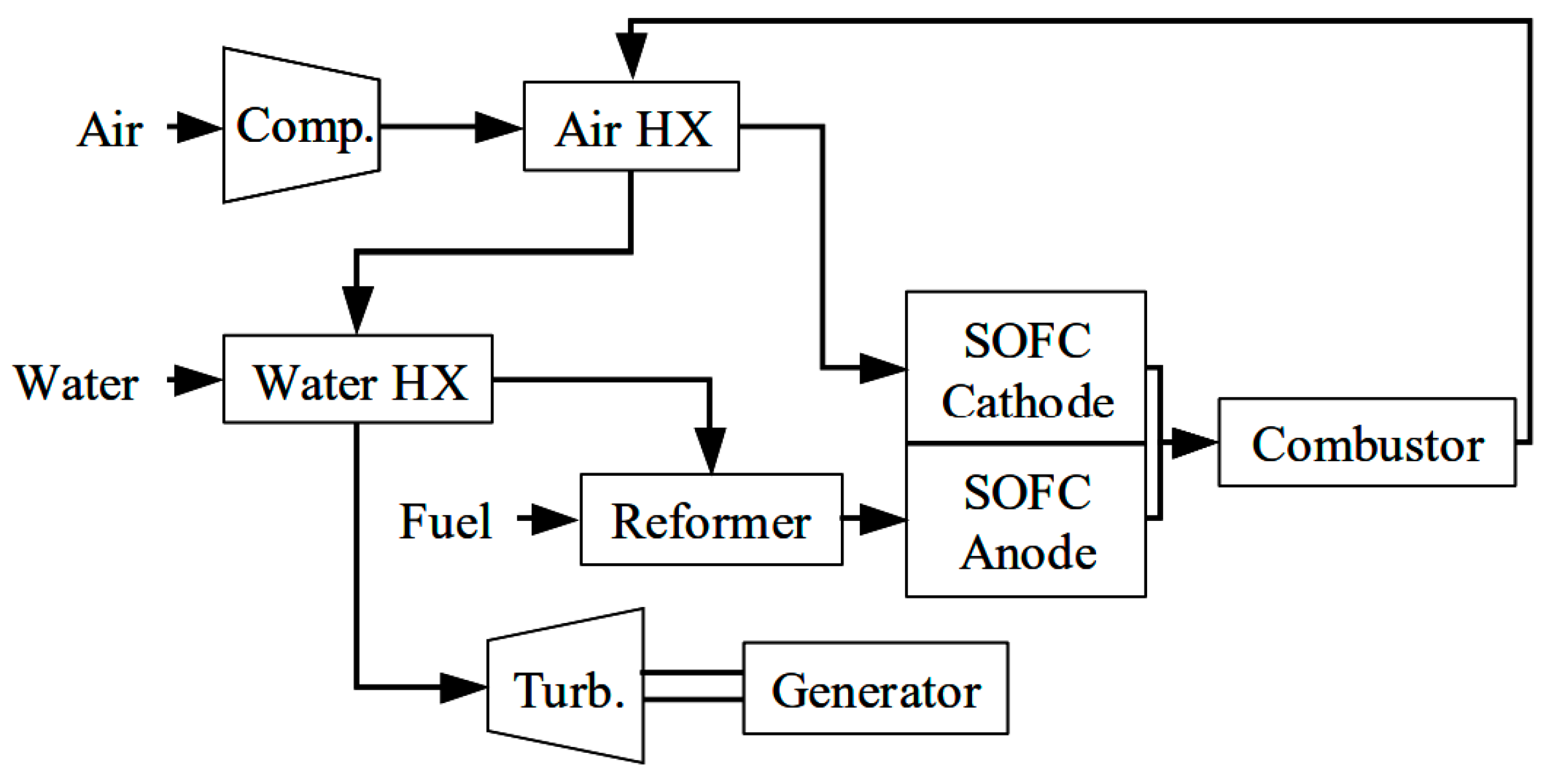
2.1. System Architecture

Available literature explores several different SOFC-GT hybrid layouts for stationary and portable applications [2,8]. The system architecture used in this study was reported by Eelman et al., where aircraft hybrid system efficiencies of up to 75% were achieved [11]. The key differences between this model (Figure 1) and our model (Figure 2) are that in our model: (1) anode exhaust recycle contains unoxidized syngas that were mixed with CO2 and steam, eliminating the water input stream after startup, (2) fuel was pumped from the fuel tank and sprayed via atomizers—ensuring a fine mist—into the external reformer minimizing heat losses, and (3) a condenser was used to recover water from the exhaust gas before ejection to the environment.

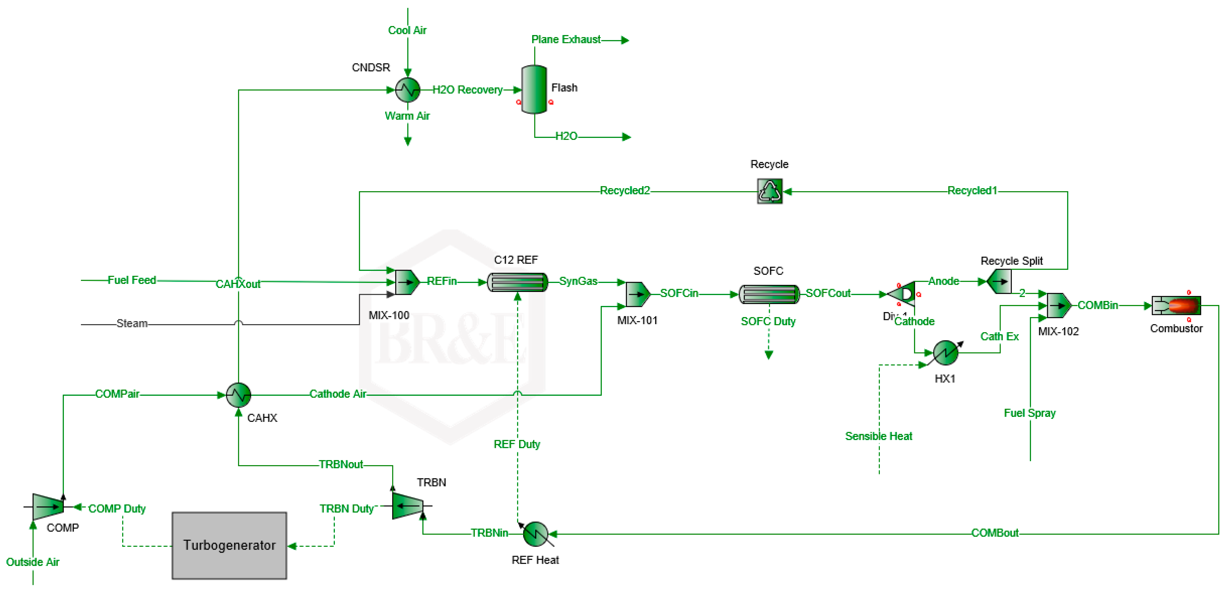
2.2. Model Development

A detailed model development is outlined, step by step, in the Supplementary Materials document for those interested in gaining an understanding of how each unit operation was set up. Key principles for the model elements that were custom-created are discussed as follows.

2.2.1. External Jet Fuel Reformer

An external reformer is often needed for SOFC-GT power systems in electric aviation to convert hydrocarbons into syngas (H2 and CO) for electrochemical oxidation to occur. In this work, n-dodecane (C12H26) was used as the synthetic jet fuel surrogate for this model since its C:H ratio and lower heating value (LHV) are close to several standard Jet-A fuel compositions. It is a one-component surrogate which simplifies modeling, validation, and steam reforming mechanisms whose results have been cited in publicly available literature. It should be noted that NPSS (the aerospace standard modeling platform used by NASA) also uses jet fuel surrogate models that contain C:H ratios and LHV rather than full mixtures of complex hydrocarbon chains. Values for a wide array of jet fuels can be sourced from the CEA thermo.inp file which contains thermodynamic component properties. Users receive the CEA source files when obtaining NPSS from NASA. The n-dodecane reforming reactions are as follows:
C 12 H 26 + 12 H 2 O 12 C O + 25 H 2
C O + H 2 O C O 2 + H 2   ( water gas   shift   reaction )
C O + 3 H 2   C H 4 + H 2 O   ( methanation )
In the last decade, n-dodecane reforming has been reported in literature with an emphasis on catalyst selection and doping, reaction space velocity, temperature/pressure sensitivity, and H2O:C ratio [25,26,27,28]. The temperatures and steam-to-carbon ratios from Guggilla et al. [25] were used with a Gibbs minimization reactor to validate the reforming process before moving forward. Figure 3 shows that the Gibbs reactor adequately matches experimental data at T > 700 °C when considering that the thermodynamic calculation set does not take into account the catalytic rates/mechanisms controlling product distribution, diffusion dependencies on reaction pressure, deviations from Water/Gas Shift (WGS), and methanation equilibrium as a function of space-time. Additionally, SOFC operating temperatures were at or above 700 °C for this study, meaning that recycled steam from the anode exhaust would be at a high enough energy state to ensure that the reforming reaction occurs in the desired temperature range.

2.2.2. SOFC Reactor Model Design

SOFCs are high temperature fuel cells that catalyze oxygen at the cathode side to form oxygen ions, which transport through a solid-state electrolyte to electrochemically oxidize fuel at the anode side, producing electricity. In a physical fuel cell one would consider the half-cell reactions as follows:
Anode Half-Cell Reactions:Cathode Half-Cell Reactions:
H 2 + 1 2 O 2 H 2 O + 2 e O 2 + 4 e   2 O 2
C O + 1 2 O 2 C O 2 + 2 e
C H 4 + 4 O 2   2 H 2 O + C O 2 + 8 e
In our model, the SOFC reactions would be the combined versions of these half-cell reactions. To do this, an oxygen conversion specification is placed in the reactor block to define the cathode air utilization—essentially defining how much oxygen ionizes and diffuses through a real fuel cell. After this oxygen conversion is reached, the model will use the Gibbs minimization calculation set to estimate the new equilibrium point for the WGS, methanation, and any other reversible reactions that could be plausible under the specified conditions.
Although the SOFC reactor block is where fuel conversions and exothermic heat are determined, the process conditions are pulled into a user value set (UVS) where the electrochemical calculations occur. The governing equations programmed into the UVS are discussed in detail by Freeh et al. [12].
An important electrochemical calculation is the reversible (Nernst) voltage:
V r e v = Δ f G ° n F + R T n F l n p H 2 × ( p O 2 ) 1 2 p H 2 O
In Equation (1), stack temperature (T) is a user input, and is assumed to be constant throughout the SOFC stack, Δf is the change in Gibbs energy of formation for gaseous water as a function of stack temperature (values derived in the model and curve fit to have a linear equation that calculates the Gibbs value at applicable temperatures from normal boiling point to 1200 °C), R is the universal gas constant, n is the number of electrons participating in the electrochemical reaction (effectively constant at 2 for this study), F is Faraday’s constant, and p is the partial pressure of a given species. As Freeh et al. explain, these partial pressures can be taken at the SOFC exit where the model is estimating the new equilibrium conditions, or they can be taken as the average across the fuel cell. For this study, the average partial pressures are used to calculate the reversible Nernst voltage [12].
While the Nernst equation provides the reversible voltage of the cell, irreversible voltage losses must be accounted for to find the operating voltage of each cell in the stack. Those losses, as well as activation, ohmic, and concentration, can be determined by [29]:
  • activation losses:
    V A c t i v a t i o n = R T n α F l n [ i + i n i o ]
  • ohmic losses:
    V o h m i c = r × ( i + i n )
  • and concentration losses:
    V C o n c e n t r a t i o n = R T n F l n [ 1 i + i n i L ]
In Equations (2)–(4); i, in, io, and iL represent the current density, internal current density, exchange current density, and limiting current density, respectively. As it is not within the scope of this work to explain the qualitative and quantitative nature of these voltage losses, further information on these can be obtained from the literature [12,29].
The area-specific resistance (ASR) term, r, necessary to determine ohmic voltage losses can exhibit a temperature dependance as shown by:
r = j r j = j A j e E j R T
In Equation (5), Aj is the pre-exponential term for electrical resistance of component j and Ej is the activation energy for electrical conduction in component j. Including a temperature dependency for total resistance is paramount since lower temperatures (e.g., 600–700 °C) lead to greater ASR than higher temperatures (e.g., 800–850 °C). If a model swings from low to high temperatures when performing sensitivity analysis, resistance as a function of temperature would produce the most accurate results. Without this dependency, the model would over-predict SOFC power generation, especially at lower temperatures.
With all voltage losses calculated, the operating voltage of the stack simply becomes:
V o p e r = V r e v V A c t i v a t i o n V O h m i c V C o n c e n t r a t i o n
To calculate stack power, a basic stack configuration must first be chosen. We assumed that all cells in each stack are connected in series, allowing us to multiply the operating voltage by the number of cells in a single stack to determine a stack voltage.
V S t a c k = V o p e r × ( N u m b e r   o f   c e l l s   i n   a   s t a c k )
We then assumed that all stacks in the system are connected in parallel. This makes total current the product of stack current and number of stacks. Those stack and total currents are as follows:
I S t a c k = 4 × F × N ˙ O 2
I T o t a l = I S t a c k × ( N u m b e r   o f   s t a c k s )
In Equation (8), N ˙ O 2 is the oxygen consumed in each individual fuel cell within each stack (assumed to be constant across all cells and stacks) and F is Faraday’s constant. In an actual fuel cell, this N ˙ O 2 term would be the amount of O2 that is ionized on the cathode surface and diffuses through the electrolyte to react with fuel on the anode surface. Within our model, the reactor block will consume the amount of O2 needed to reach the specified fuel utilization. This O2 molar consumption rate (mol/sec) within the reactor block is divided by the number of stacks in the system and then the number of cells in each stack to get the cell-level N ˙ O 2 value.
N ˙ O 2 = ( S O F C   R e a c t o r   B l o c k   O x y g e n   C o n s u m p t i o n   R a t e ) [ m o l / s e c ] ( N u m b e r   o f   s t a c k s   i n   s y s t e m ) × ( N u m b e r   o f   c e l l s   i n   s t a c k )
With stack voltage and total current defined, the SOFC power is simply:
P S O F C = V S t a c k × I T o t a l 1000
The model calculates the amount of heat consumed or expelled in reactor blocks by taking the enthalpy difference between the inlet and exit streams. To find the heat generated by the SOFC stack one simply subtracts the calculated SOFC power from the value in this energy stream:
Q ˙ g e n = Δ H ˙ P S O F C
Finally, Freeh et al. define the overall stack efficiency and the stack electrical efficiency terms by [12]:
η O v e r a l l = U f × P S O F C Δ H ˙
where the stack fuel utilization (Uf) is:
U f = Δ ( I N O U T ) ( N ˙ H 2 + N ˙ C O + N ˙ C H 4 ) ( N ˙ H 2 + N ˙ C O + N ˙ C H 4 ) I N
and electrochemical efficiency is:
η E l e c t r o c h e m = V o p e r V r e v
The final correlation needed for certain SOFC calculations (especially when fitting the model against experimental data) is an equation that corrects for pressure when calculating SOFC operating voltage. When using thermodynamic Gibbs minimization calculation types in ProMax, Aspen, or NPSS to model SOFCs, there are no kinetic or diffusion parameters involved. This can cause voltage vs current density results from chemical process simulators to deviate from experimental data at pressures above 1 atm [12]. The correction factor Freeh et al. presents is as follows:
i L = i L × ( p o p o ) a
where a is an iterable constant, po is the pressure, and the primed variables are those variables at atmospheric conditions.

3. Results

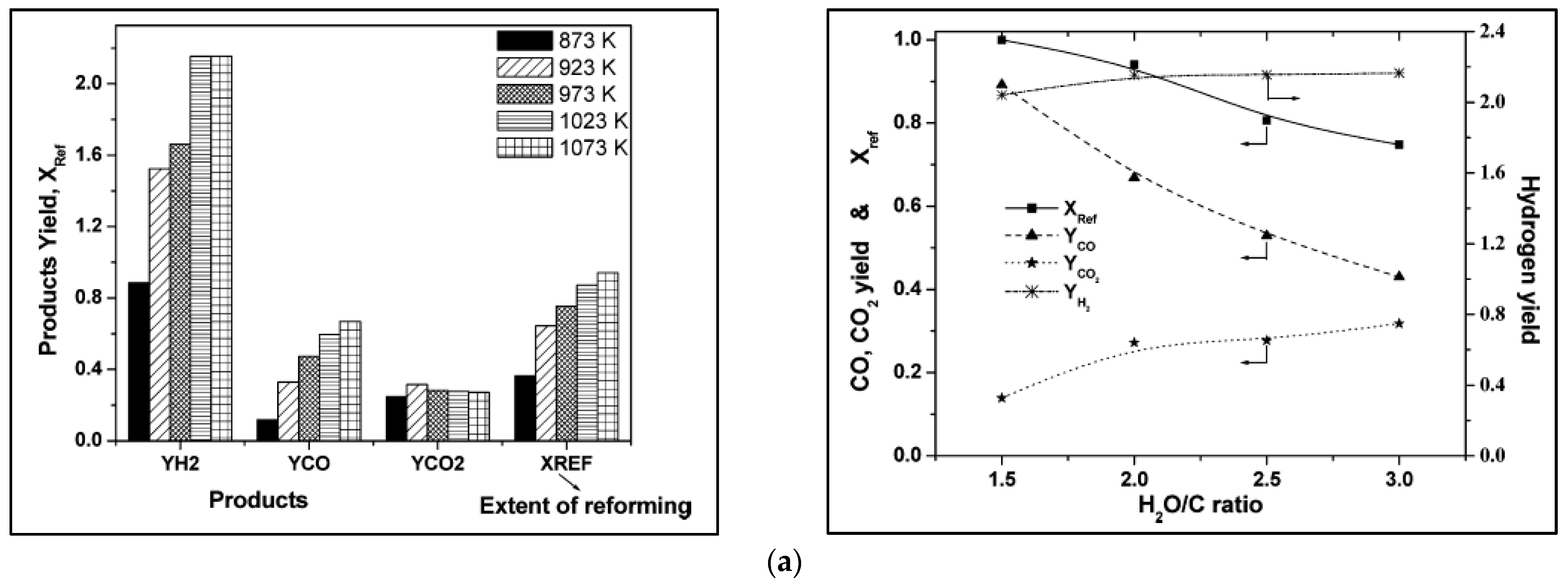
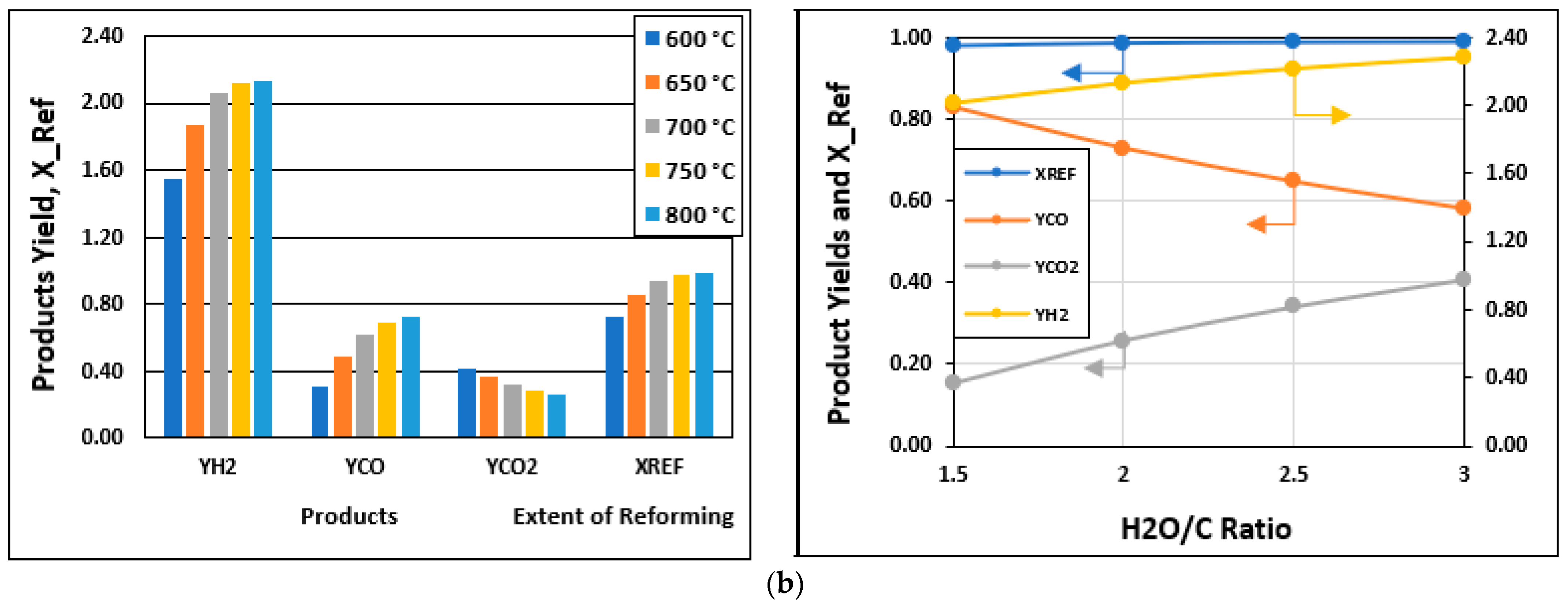
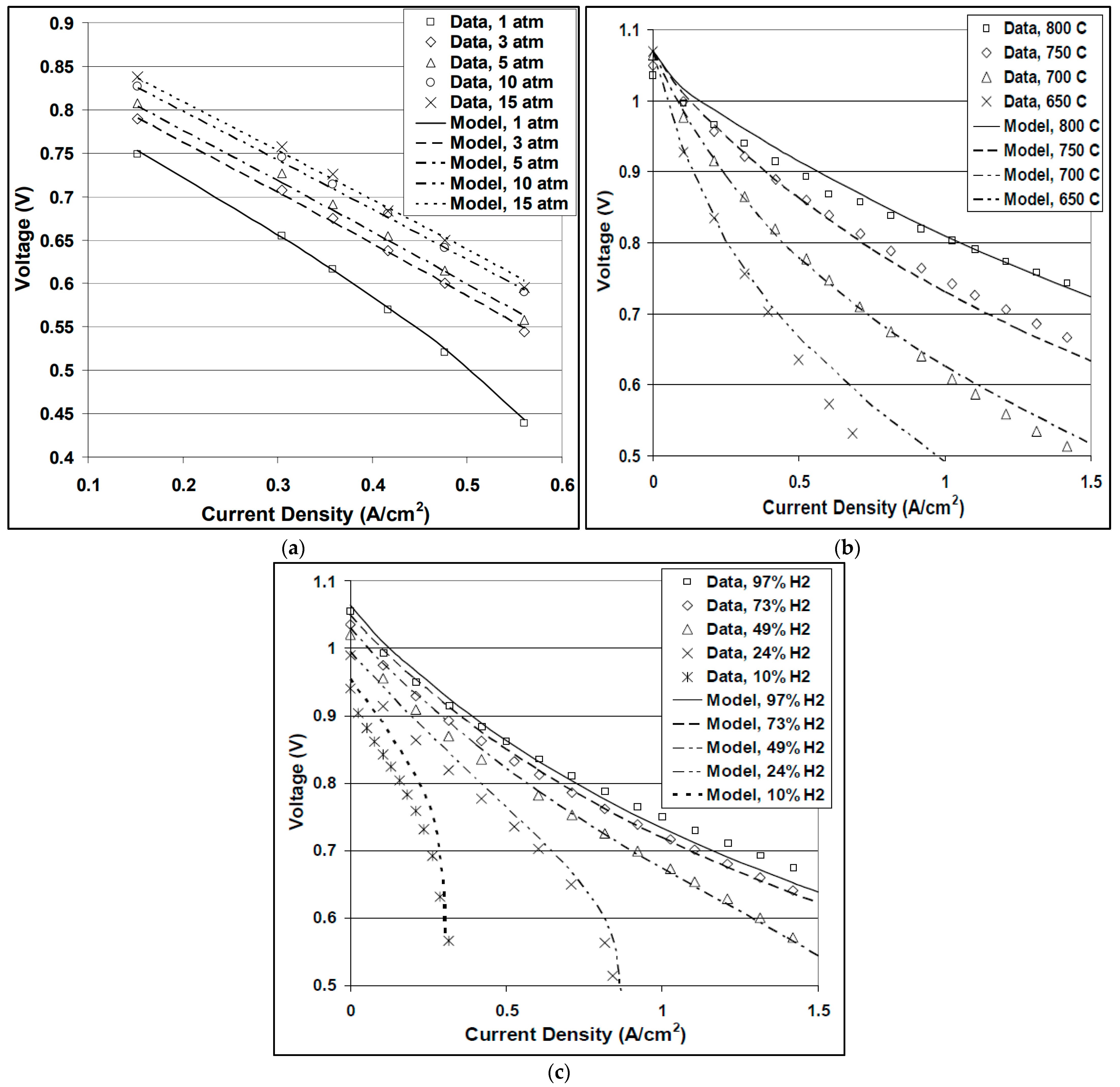
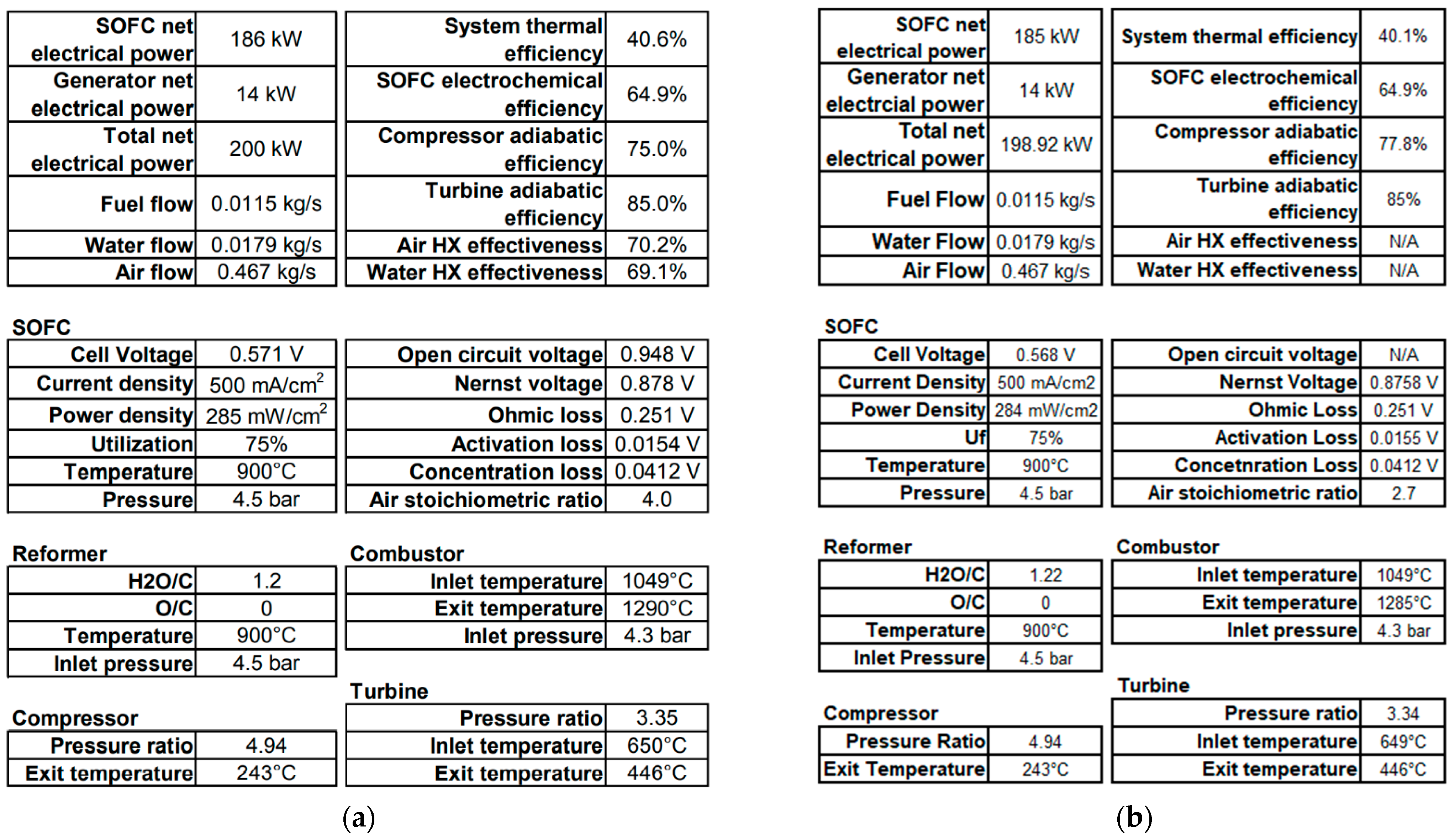
3.1. Model Validation

Before generating system-level data, our model was validated to ensure that the model results were reliable. Initial simulations contained only the SOFC reactor block and design equations to collect the preliminary results. Following the lead set by NASA’s Josh Freeh et al., we validated our SOFC model against Siemens Westinghouse stack pressure data from their tubular cells produced in the late 1990s and against Pacific Northwest National Lab’s (PNNL) temperature and anode feed composition data from their planar button cells in the early 2000s [12]. Figure 4 shows Freeh’s NPSS model results plotted against the experimental data, while Figure 5 shows our simulation outputs under the same conditions (cell resistances, current densities, empirical values, etc.). Our results were extremely promising as they compared well to both the experimental cells and the NPSS model.
One of the most promising benefits to reproducing experimental fuel cell work in our model is that although this validated data are 20 years old, current and state-of-the-art data can be validated just as easily in several different ways. First, if the total cell resistances and the operating, internal, exchange, and limiting current densities are known, they can be input in the model using the Nernst and voltage loss equations outlined above, and instantaneous results can be acquired. This is very powerful because if our model can validate both previous and current data, one can take projected resistances, current densities, etc., from 5 to 30 years out and generate predicted performances for comparison against current data. Secondly, if a research group does not have access to the electrochemical values necessary to build this traditional model, but still has access to V-I curve data, then those plots could be fit to the curve and the resulting polynomials could be coded into our model, using the ProMax UVS function, to get the operating voltage at any known current density in the design/simulation space. If using this second approach, special care should be taken to account for temperature dependencies so that the model does not overpredict SOFC performance.
Once our SOFC model proved to perform well against experimental stack data generated by Siemens Westinghouse and PNNL, the first hybrid system model was built to reflect NASA’s NPSS system model. Figure 6 is the Freeh et al. hybrid system schematic which we emulated in our model. For this NPSS model, NASA specified the use of Jet-A fuel. We were able to extract the C:H ratio and LHV of Jet-A from the NPSS CEA source files. Jet-A has a C:H ratio of 12:23 and an LHV of 18,500 Btu/lb (43,031 kJ/kg). We used a 1:0.562463 molar ratio of n-dodecane to m-xylene (12:23 C:H ratio, LHV of 18,546 Btu/lb (43,138 kJ/kg)) as the fuel surrogate. Results from our validation model are compared to the NPSS model results in Figure 7.

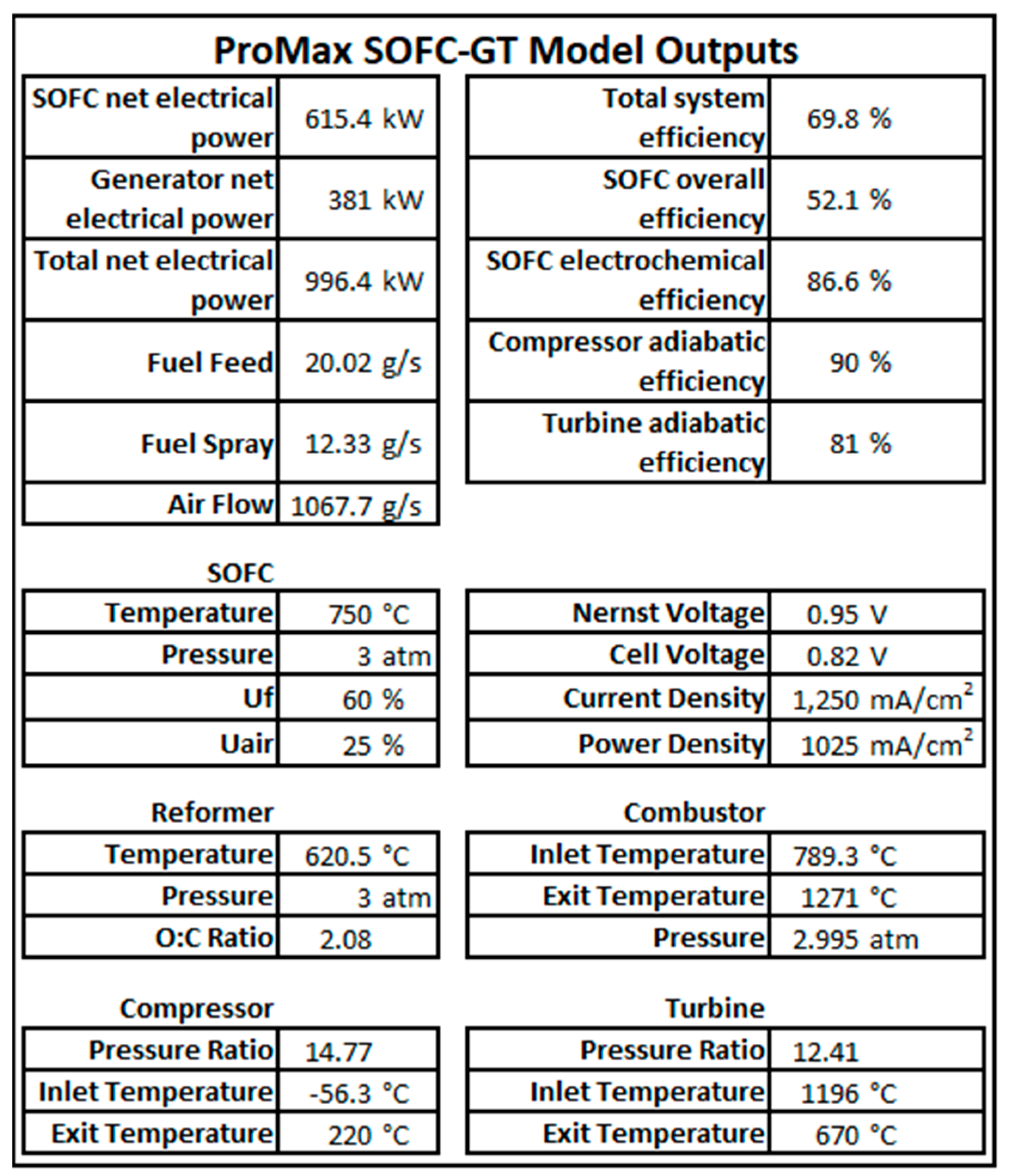
3.2. Model Performance

Once our model was validated, a new 1-MW hybrid SOFC architecture was constructed to match the commercial airplane system layout that was presented in Figure 2. System design specification ranges and operating input variables are shown in Table 2.
For one system operating point at an aircraft cruise altitude of 36,000 feet (10,973 m), Figure 8 illustrates the design inputs and calculated operating outputs for a (combined) 1-MW system using a synthetic liquid fuel similar to Jet-A.

4. Discussion

4.1. Interpretation

Users can obtain fuel and air flow requirements, SOFC electrochemical operating data, and unit specific values for detailed design and evaluation from the simulation. This serves as a baseline from which performance and sensitivity analyses can be conducted through ProMax’s scenario tool. By establishing iteration arrays, our model can change input variables and re-execute to report the desired scenario data. One example is a compressor air flow requirement scenario to determine the flowrates needed to maintain a 1.25 A/cm2 current density for the SOFC stacks as air utilization (Uair) is swept from 17% to 25%. Air flow rates for a six and seven fuel cell stack system are shown in Figure 9.

4.2. Implications

Once an optimal hybrid SOFC system has been configured and analyzed with this model, it can be coupled with the ProMax scenario tool, enabling users to evaluate steady-state hybrid SOFC system performance over entire flight envelopes. Since the required system electrical output is a direct function of flight envelope, thousands of simulation iterations may be needed to evaluate the optimal system operating conditions at each major flight envelope stage. This scenario tool allows researchers and industry groups to perform efficient and facile sensitivity and performance analyses at each of these stages. Additionally, the adaptable nature of this ProMax model—specifically the SOFC model integrated within a robust process modelling environment—means the presented methods can be applied to nearer term electrical applications such as ground power units, electric automobile and truck range extenders, RV auxiliary power units, UAV propulsion, aircraft APUs, and even oil and gas feasibility studies and process design, as renewable/alternative energy systems get integrated into existing processes.

4.3. Limitations

While this hybrid SOFC power system’s modeled expectations of higher FTE efficiencies are attractive, there are still a few model design challenges to be addressed. The steady-state, thermodynamic nature of this modeling package means that it is unable to perform dynamic simulations that will be needed to evaluate the response times of the supporting turbomachinery and to account for the gas volume of various SOFC supporting components, such as heat exchangers. While future studies will likely look to integrate high-fidelity kinetic and diffusion-based SOFC models (which ProMax is well-equipped to handle), the current thermodynamic model does not account for the reactor residence times, catalytic effects on product distribution and operating pressure.

5. Conclusions

We developed and validated a system-level model for a high-performance SOFC-GT hybrid power system using the ProMax simulation software. The guiding principles have been outlined and a detailed description of the model’s development is included in the Supplementary Materials documents. Our model showed fuel-to-electricity conversion efficiency levels that are much higher than traditional gas turbine engines fitted with electrical generators. These efficiency benefits will be essential to enable the development of future fully electric, long-range commercial aircraft. Such electric aircraft will be needed if the aviation sector truly intends to achieve net zero emissions through the use of carbon neutral fuels (to power the SOFC) which tend to be substantially more expensive to produce and are currently limited in production capacity.
Additional system-level modeling, especially performance and sensitivity analyses, are required to gain a better understanding of how to best address the balance of plant design challenges, some of which were presented here. Furthermore, continued progress in the integration of high fidelity SOFC models into established process simulation software may be necessary to garner interest in commercializing these technologies and stimulate R&D.

Supplementary Materials

The following supporting information can be downloaded at: https://0-www-mdpi-com.brum.beds.ac.uk/article/10.3390/en15082885/s1. The full model development and reformer/SOFC stream properties are available in the supporting documentation. Additional data can be provided by the research team upon request.

Author Contributions

Conceptualization, X.-D.Z.; data curation, J.A.W. and D.D.; formal analysis, J.A.W.; funding acquisition, X.-D.Z.; investigation, J.A.W.; methodology, J.A.W.; project administration, X.-D.Z.; software, J.A.W.; supervision, D.D. and X.-D.Z.; validation, J.A.W.; visualization, J.A.W. and J.C.; writing—original draft, J.A.W.; writing—review and editing, Y.W., J.R., G.A., E.D., S.S. (Scott Swartz), D.D., S.S. (Subhash Singhal), and X.-D.Z. All authors have read and agreed to the published version of the manuscript.

Funding

This work was supported by a US Department of Energy ARPA-E Project under the agreement DE-AR0001346.

Conflicts of Interest

These authors declare no conflict of interest. BR&E/ProMax nor ARPA-E had any role in the design of the study, in the collection, analysis, or interpretation of data; in the writing of the manuscript; or in the decision to publish the results.

Nomenclature

Symbol (Units)Description
Aj (kΩ·cm2)Pre-exponential resistance term of component j
Ej (J·mol−1)Active energy for electrical conduction in component j
F (C·mol−1)Faraday constant
I (mA·cm−2)Current density
iL (mA·cm−2)Limiting current density
in (mA·cm−2)Internal current density
io (mA·cm−2)Exchange current density
n (-)Number of electrons transferred per mole of reactant
P (J·mol−1)Power
po (atm)Pressure
p (-)(as a prefix) partial pressure
Q ˙ (J·mol−1)Heat flow rate
r (kΩ·cm2)Area-specific resistance term (combines both ionic and electronic resistances)
R (J·K−1·mol−1)Universal gas constant
T (K)Temperature
Uf (-)Overall stack utilization
V (-)Voltage
ΔfG° (J·mol−1)Change in Gibbs energy of formation at standard pressure
Δ H ˙ (J·sec−1)Enthalpy flow rate
N ˙ (mol·sec−1)Molar flow rate
a (-)Empirically derived charge transfer coefficient
η (-)Efficiency

References

  1. Baldi, F.; Wang, L.; Pérez-Fortes, M.; Maréchal, F. A Cogeneration System Based on Solid Oxide and Proton Exchange Membrane Fuel Cells with Hybrid Storage for Off-Grid Applications. Front. Energy Res. 2019, 6, 139. [Google Scholar] [CrossRef]
  2. Damo, U.M.; Ferrari, M.L.; Turan, A.; Massardo, A.F. Solid oxide fuel cell hybrid system: A detailed review of an environmentally clean and efficient source of energy. Energy 2019, 168, 235–246. [Google Scholar] [CrossRef] [Green Version]
  3. Kwan, T.H.; Katsushi, F.; Shen, Y.; Yin, S.; Zhang, Y.; Kase, K.; Yao, Q. Comprehensive review of integrating fuel cells to other energy systems for enhanced performance and enabling polygeneration. Renew. Sustain. Energy Rev. 2020, 128, 109897. [Google Scholar] [CrossRef]
  4. Singh, M.; Zappa, D.; Comini, E. Solid oxide fuel cell: Decade of progress, future perspectives and challenges. Int. J. Hydrogen Energy 2021, 46, 27643–27674. [Google Scholar] [CrossRef]
  5. Tucker, M.C. Progress in metal-supported solid oxide fuel cells: A review. J. Power Sources 2010, 195, 4570–4582. [Google Scholar] [CrossRef]
  6. Hagen, A.; Wulff, A.C.; Zielke, P.; Sun, X.; Talic, B.; Ritucci, I.; Frandsen, H.L.; Jensen, S.H.; Kiebach, W.R.; Hendriksen, P.V. SOFC stacks for mobile applications with excellent robustness towards thermal stresses. Int. J. Hydrogen Energy 2020, 45, 29201–29211. [Google Scholar] [CrossRef]
  7. Cho, S.; Kim, Y.; Kim, J.H.; Manthiram, A.; Wang, H. High power density thin film SOFCs with YSZ/GDC bilayer electrolyte. Electrochim. Acta 2011, 56, 5472–5477. [Google Scholar] [CrossRef]
  8. Fernandes, M.D.; Andrade, S.D.P.; Bistritzki, V.N.; Fonseca, R.M.; Zacarias, L.G.; Gonçalves, H.N.C.; de Castro, A.F.; Domingues, R.Z.; Matencio, T. SOFC-APU systems for aircraft: A review. Int. J. Hydrogen Energy 2018, 43, 16311–16333. [Google Scholar] [CrossRef]
  9. Buonomano, A.; Calise, F.; d’Accadia, M.D.; Palombo, A.; Vicidomini, M. Hybrid solid oxide fuel cells–gas turbine systems for combined heat and power: A review. Appl. Energy 2015, 156, 32–85. [Google Scholar] [CrossRef]
  10. Daggett, D.; Rajashekara, K.; Grieve, J. Solid Oxide Fuel Cell/Gas Turbine Hybrid APU System for Aerospace Applications. In Proceedings of the Conference Record of the 2006 IEEE Industry Applications Conference Forty-First IAS Annual Meeting, Tampa, FL, USA, 8–12 October 2006. [Google Scholar]
  11. Eelman, S.; Daggett, D.; Zimmermann, M.; Seidel, G. High Temperature Fuel Cells as Substitution of the Conventional APU in Commercial Aircraft. Ger. Aerosp. Congr. 2003, 183, 1601–1608. [Google Scholar]
  12. Freeh, J.E.; Pratt, J.W.; Brouwer, J. Development of a Solid-Oxide Fuel Cell/ Gas Turbine Hybrid System Model for Aerospace Applications. In Power for Land, Sea, Air–Turbo Expo; American Society of Mechanical Engineers: New York, NY, USA, 2004. [Google Scholar]
  13. ben Moussa, H.; Zitouni, B.; Oulmi, K.; Mahmah, B.; Belhamel, M.; Mandin, P. Hydrogen consumption and power density in a co-flow planar SOFC. Int. J. Hydrogen Energy 2009, 34, 5022–5031. [Google Scholar] [CrossRef]
  14. Suther, T.; Fung, A.; Koksal, M. Simulation of a Solid Oxide Fuel Cell-Gas Turbine System Using AspenPlus. In Proceedings of the 3rd International Energy, Exergy and Environment Symposium, Evora, Portugal, 1–5 July 2007; Bibliothèque et Archives: Ottawa, ON, Canada, 2007. [Google Scholar]
  15. Calise, F.; Dentice d’Accadia, M.; Palombo, A.; Vanoli, L. Simulation and exergy analysis of a hybrid Solid Oxide Fuel Cell (SOFC)–Gas Turbine System. Energy 2006, 31, 3278–3299. [Google Scholar] [CrossRef]
  16. Bakalis, D.P.; Stamatis, A.G. Full and part load exergetic analysis of a hybrid micro gas turbine fuel cell system based on existing components. Energy Convers. Manag. 2012, 64, 213–221. [Google Scholar] [CrossRef]
  17. Magistri, L.; Traverso, A.; Cerutti, F.; Bozzolo, M.; Costamagna, P.; Massardo, A.F. Modelling of Pressurised Hybrid Systems Based on Integrated Planar Solid Oxide Fuel Cell (IP-SOFC) Technology. Fuel Cells 2005, 5, 80–96. [Google Scholar] [CrossRef]
  18. Li, J.; Cao, G.Y.; Zhu, X.J.; Tu, H.Y. Two-dimensional dynamic simulation of a direct internal reforming solid oxide fuel cell. J. Power Sources 2007, 171, 585–600. [Google Scholar] [CrossRef]
  19. Mueller, F.; Brouwer, J.; Jabbari, F.; Samuelsen, S. Dynamic Simulation of an Integrated Solid Oxide Fuel Cell System Including Current-Based Fuel Flow Control. J. Fuel Cell Sci. Technol. 2005, 3, 144–154. [Google Scholar] [CrossRef]
  20. Bove, R.; Lunghi, P.; MSammes, N. SOFC mathematic model for systems simulations. Part one: From a micro-detailed to macro-black-box model. Int. J. Hydrogen Energy 2005, 30, 181–187. [Google Scholar] [CrossRef]
  21. Palsson, J.; Selimovic, A.; Sjunnesson, L. Combined solid oxide fuel cell and gas turbine systems for efficient power and heat generation. J. Power Sources 2000, 86, 442–448. [Google Scholar] [CrossRef]
  22. Musa, A.; de Paepe, M. Performance of combined internally reformed intermediate/high temperature SOFC cycle compared to internally reformed two-staged intermediate temperature SOFC cycle. Int. J. Hydrogen Energy 2008, 33, 4665–4672. [Google Scholar] [CrossRef]
  23. Zhang, X.; Li, J.; Li, G.; Feng, Z. Dynamic modeling of a hybrid system of the solid oxide fuel cell and recuperative gas turbine. J. Power Sources 2006, 163, 523–531. [Google Scholar] [CrossRef]
  24. Bao, C.; Wang, Y.; Feng, D.; Jiang, Z.; Zhang, X. Macroscopic modeling of solid oxide fuel cell (SOFC) and model-based control of SOFC and gas turbine hybrid system. Prog. Energy Combust. Sci. 2018, 66, 83–140. [Google Scholar] [CrossRef]
  25. Guggilla, V.S.; Akyurtlu, J.; Akyurtlu, A.; Blankson, I. Steam Reforming of n-Dodecane over Ru−Ni-Based Catalysts. Ind. Eng. Chem. Res. 2010, 49, 8164–8173. [Google Scholar] [CrossRef]
  26. Li, L.; Shang, Z.; Xiao, Z.; Wang, L.; Liang, X.; Liu, G. Steam reforming of n-dodecane over mesoporous alumina supported nickel catalysts: Effects of metal-support interaction on nickel catalysts. Int. J. Hydrogen Energy 2019, 44, 6965–6977. [Google Scholar] [CrossRef]
  27. Li, L.; Zuo, S.; An, P.; Wu, H.; Hou, F.; Li, G.; Liu, G. Hydrogen production via steam reforming of n-dodecane over NiPt alloy catalysts. Fuel 2020, 262, 116469. [Google Scholar] [CrossRef]
  28. Kim, T.; Chung, Y.S.; Sung, J.G.; Kim, H.; Park, S.; Jung, H.K.; Park, S.; Kim, W.B.; Chung, J.S. n-Dodecane steam reforming over Ni catalysts supported on ZrO2–KNbO3. J. Power Sources 2020, 479, 228834. [Google Scholar] [CrossRef]
  29. Dicks, A.L.; Rand, D.A.J. Fuel Cell Systems Explained; Wiley: New York, NY, USA, 2018. [Google Scholar] [CrossRef]
Figure 1. SOFC-GT APU system design as presented by Eelman et al. [11].
Energies 15 02885 g001
Figure 2. SOFC-GT system flowsheet in ProMax.
Energies 15 02885 g002
Figure 3. (a) n-dodecane experimental reforming results [25]. (b) Thermodynamic calculation based on a Gibbs reactor.
Energies 15 02885 g003aEnergies 15 02885 g003b
Figure 4. NPSS SOFC model results for (a) Siemens Westinghouse stack pressure data (b) PNNL temperature data and (c) PNNL anode feed composition data.
Energies 15 02885 g004
Figure 5. Our SOFC model data results validated against (a) Siemens Westinghouse stack pressure data (b) PNNL temperature data and (c) PNNL anode feed composition data.
Energies 15 02885 g005
Figure 6. NASA’s NPSS SOFC/GT hybrid system architecture [12].
Energies 15 02885 g006
Figure 7. (a) NASA’s hybrid system results and (b) Our results with same process conditions.
Energies 15 02885 g007
Figure 8. Our hybrid SOFC model for a 1-MW hybrid system operated at 36,000 ft (10,973 m) cruise altitude.
Energies 15 02885 g008
Figure 9. Scenario example for cathode air flow needed to maintain 1.25 A/cm2 from 17% to 25% air utilization.
Energies 15 02885 g009
Table 1. Collection of system-level SOFC studies according to modeling environment.
ModulesExcel/MATLABNPSS (CEA)AspenPlusProMax
SOFCPre-built PackageN/AN/AN/AN/A
Thermodynamic Model
  • Daggett et al. (Boeing) [10]
  • Eelman et al. (Munich) [11]
  • Freeh et al. (NASA) [12]
  • Ben Moussa et al. [13]
  • Suther et al. [14]
  • Calise et al. [15]
  • Bakalis et al. [16]
• Capable with Gibbs Reactor
Kinetic/Diffusion Models
  • Magistri et al. (Rolls-Royce) [17]
  • Li et al. [18]
  • Mueller et al. [19]
  • Bove et al. (blackbox SOFC) [20]
N/A
  • Palsson et al. [21]
  • Musa et al. [22]
  • Zhang et al. [23]
• Kinetics capable with Reactor Block or both capable with inherent Excel extension
TurbomachineryCompressor Model
  • Daggett et al. (Boeing) [10]
  • Eelman et al. (Munich) [11]
  • Magistri et al. (Rolls-Royce) [17]
  • Freeh et al. (NASA) [12]
  • Suther et al. [14]
  • Calise et al. [15]
  • Bakalis et al. [16]
  • Palsson et al. [21]
  • Musa et al. [22]
  • Zhang et al. [23]
• Compressor Blocks included
Turbine Model• Turbine Blocks included
Generator
  • Daggett et al. (Boeing) [10]
  • Eelman et al. (Munich) [11]
• Capable with calculators or FORTRAN• Capable in User Value Sets or inherent Excel extension
External ReformerThermodynamic Model
  • Daggett et al. (Boeing) [10]
  • Eelman et al. (Munich) [11]
  • Freeh et al. (NASA) [13]
  • Suther et al. [14]
  • Calise et al. [15]
  • Bakalis et al. [16]
• Capable with Gibbs Reactor
Kinetic Model
  • Magistri et al. (Rolls-Royce) [17]
  • Mueller et al. [19]
N/A
  • Palsson et al. [21]
  • Musa et al. [22]
• Capable with Reactor Block
CombustorThermodynamic Model
  • Daggett et al. (Boeing) [10]
  • Eelman et al. (Munich) [11]
  • Freeh et al. (NASA) [12]
  • Suther et al. [14]
  • Calise et al. [15]
  • Bakalis et al. [16]
• Capable with Gibbs Reactor (set Gibbs type to burner)
Kinetic Model
  • Magistri et al. (Rolls-Royce) [17]
  • Mueller et al. [19]
N/A
  • Palsson et al. [21]
  • Musa et al. [22]
• Capable with Reactor Block
Table 2. Summary of top-level specifications for this model of aviation hybrid SOFC system.
ParameterValue
Reactor Calculation TypesGibbs Minimization (Reformer, SOFC, and Combustor)
Altitude36,000 ft (10,973 m)
External Reformer Jet Fuel Conversion99%
Reformer Oxygen/Carbon Ratio1.8–3.0 (allowed to float within this range)
SOFC Stack Temperature700–850 °C
SOFC Stack Pressure1–16 atm
SOFC Configuration:
Cell Active Area 500 cm2
Cells per Stack (connected in series) 200
# of Stacks (connected in parallel) 6
SOFC Anode Gas Recycle Fraction70%
Cathode Pressure Drop5%
Heat Exchanger Pressure Drops3%
Publisher’s Note: MDPI stays neutral with regard to jurisdictional claims in published maps and institutional affiliations.

