
Heat Recovery from a Wastewater Treatment Process—Case Study

1
Faculty of Maritime Technology and Transport, West Pomeranian University of Technology in Szczecin, al. Piastów 17, 70-310 Szczecin, Poland
2
Faculty of Civil and Environmental Engineering, West Pomeranian University of Technology in Szczecin, al. Piastów 17, 70-310 Szczecin, Poland
*
Author to whom correspondence should be addressed.
Energies 2023, 16(1), 44; https://0-doi-org.brum.beds.ac.uk/10.3390/en16010044
Submission received: 24 October 2022
/
Revised: 8 December 2022
/
Accepted: 16 December 2022
/
Published: 21 December 2022
(This article belongs to the Special Issue Waste Water Treatment and Energy Recovery: Opportunities and Challenges)
Abstract
:This article presents the potential of heat recovery from wastewater with an example of a wastewater treatment plant (WWTP) in Mokrawica, which is located in the West Pomeranian region of Poland. A thorough literature review discusses the relevance of the topic and shows examples of heat recovery conducted with heat pumps. Raw and treated wastewater are mostly used as heat sources, with the latter achieving higher thermal capacities. Heat recovery from a biological treatment process is rarely implemented and requires more detailed studies on this subject. The proposed methodology for estimating possible heat recovered from wastewater, requiring heating and cooling capacities, as well as the coefficient of performance (COP) of a heat pump, is based on only three parameters: wastewater volumetric flow, wastewater temperature, and the required temperature for heating or air-conditioning. The heat recovery potential was determined for different parts of WWTP processes, i.e., the sand box, aeration chamber, secondary sedimentation tank, and treated sewage disposal. The average values of 309–451 kW and a minimum of 58–68 kW in winter were determined. The results also indicate that, depending on the location of the heat recovery, it is possible to obtain from wastewater between 57.9 kW and 93.8 kW of heat or transfer to wastewater from 185.9 to 228.2 kW. To improve biological treatment processes in the winter season, wastewater should be preheated with a minimum of 349–356 kW that can be recovered from the treated wastewater. The heat transferred to the wastewater from the air-conditioning system amounts to 138–141 kW. By comparing the required cooling and heating capacities with the available resources, it is possible to fully recover or transfer the heat for central heating, hot water, and air conditioning of the building. Partial preheating of wastewater during the treatment process requires further analysis.
1. Introduction
In recent years, there has been a growing interest in using low-temperature heat found in wastewater, right from the wastewater generation point, along the sewage pipes, and up to the wastewater treatment plant [1,2,3,4,5,6,7,8,9,10,11,12,13,14,15,16,17,18,19,20,21,22,23,24,25]. This is due to the fact that traditional conventional heating technologies based on the combustion of solid, liquid, or gaseous fuels are limited in terms of availability and quantity of fossil fuel, the efficiency of combustion heat utilization, and environmental pollution. Therefore, the development of low-carbon energy generation technologies in accordance with the idea of sustainable development is gaining momentum. A significant increase in the application of heat pumps as alternative high-efficiency heating devices has been observed [26,27,28,29].
Municipal wastewater is considered a very good, stable source of heat, with relatively high temperature and volume flux [30,31,32]. The heat from wastewater does not have a high enough temperature to be used directly for heating domestic hot water or buildings but can be used to recover heat with heat pumps [1,12,33]. Heat can be recovered from both raw wastewater, during the treatment process, and after treatment [34,35].
An important limitation when using untreated wastewater for the purpose of heat recovery is the influent temperature, which is a parameter that closely affects the rate of pollutant decomposition in biological treatment processes. These processes die down when the temperature is lowered below 5 °C [36,37]. Elias-Maxil [38] describes a case where a rapid decrease in the temperature for a few hours (due to precipitation) did not negatively affect the biological processes due to the high thermal inertia of the wastewater and the retention time in the tanks. In case of a longer decrease in temperature (longer precipitation), a slowing down of the nitrification process by 10% was observed for a temperature decrease of 1 °K.
It is worth noting that the solubility of oxygen and the related amount of air necessary for the aeration process change with the change in wastewater temperature [39,40,41,42]. The aeration process is one of the most energy-consuming processes in a WWTP [39,43]. As a result of heat recovery, the temperature decreases, which causes a reduction in the amount of aeration air, and thus a reduction in the energy consumption of the treatment plant.
A study conducted by Cecconet et al. [44] has shown that in case of increased widespread wastewater heat recovery for buildings’ own use, there is a risk of a significant change in the temperature of the wastewater entering the treatment plant.
Kretschmer et al. [45] presented a procedure for identifying and evaluating potential wastewater heat recovery sites based on temperature changes along the sewer network. The proposed evaluation criteria include both the correlation between the heat recovery potential and the heat demand, as well as the effect of recovery on the temperature of the wastewater flowing into the treatment plant.
Different studies [1,7,12,27,30,34,44,46,47,48,49] presented a review of possible solutions for obtaining residual heat for central heating and hot water of buildings.
Shen et al. [31] discussed heat pump exchangers used for heat recovery in a wastewater treatment plant (WWTP), along with a description of their surface cleaning capabilities. The authors also indicated that contaminants smaller than 4 mm in size are the main cause of surface contamination. Typical solutions for indirect or direct heat exchange between wastewater and heat pump are compact exchangers: plate, shell-and-tube, spray, or immersion type. In addition to the previously mentioned, HDPE coils can also be used.
Thermal energy can be recovered from wastewater in a direct or indirect way [49,50]. The direct method faces the issue of the size and volume of refrigerant for the heat pump installation or the need to pump the wastewater through the heat pump exchanger. On the other hand, the indirect method is regarded as more universal, also enabling heat recovery from unprocessed wastewater [51]. However, this method requires higher initial investments due to the use of heat exchange intermediary circuits and the problems of contamination of the exchanger’s surfaces [34].
Examples of heat recovery using a heat pump are listed in Table 1. Generally, both raw and treated wastewater are used as a heat source, with the latter achieving higher thermal capacities. Heat recovery from biological treatment sites is a rare solution and there are no detailed studies on this subject.
This paper explores the potential of heat recovery from a WWTP by integrating a heat pump system. A methodology for estimating heat resources and the required heat capacities of a heat pump was proposed based on only three parameters: wastewater volumetric flow, wastewater temperature, and the required temperature for heating purposes.
Based on the measurement data, the heat recovery potential of the WWTP at specific locations and for different stages of wastewater treatment was determined. The calculations show: (1) how much heat could be supplied by a heat pump under the existing conditions over the year; (2) what cooling capacities can be provided by the heat pump for air-conditioning; (3) how much heat is needed for preheating of wastewater to improve biological treatment processes in the winter season.
2. Methodology
2.1. Facility/System Description
Wastewater test results were obtained from PGK in Kamien Pomorski, Poland. Based on those results, the possibility of heat recovery from the Mokrawica wastewater treatment plant (WWTP) was calculated for the different stages of wastewater treatment.
The studied site is located in Mokrawica village, which is situated in West Pomeranian Voivodeship, Kamień Pomorski County and Municipality.
Pollution load is estimated to be about 10,000 people equivalents (P.E.), without local heavy industry.
The quality of treated sewage meets the following requirements [54]:
BOD: 15 g O2/m3, COD: 125 g O2/m3, total suspension: 35 g/m3, nitrogen total: 15 g N/m3, phosphorus total: 2 g P/m3,
Wastewater influent [55]:
without rainfall: Qh,max = 359 m3/h,
with rainfall: Qh,max = 669 m3/h.
The facility implements the wastewater treatment process using a modification of the Bardenpho (A2/O) three-stage system, involving the use of additional chambers: transitional nitrification, providing extended aeration time with enhanced biological phosphatation, and predenitrification/retention, for initial denitrification of recycled sludge or wastewater collection [55].
The basic layout of the studied WWTP is shown in Figure 1.
2.2. Meteorological Data
According to the data [56,57], the Kamien Pomorski commune is located in region A—Baltic Climate—which occurs in a narrow strip along the coast and is characterised by warm winters, generally cool summers, and relatively frequent strong winds. The climate is mild, with a long growing season with plenty of precipitation. The average annual temperature: 8–8.5 °C; average January temperature: −0.5–−1.0 °C; average July temperature: 17–17.5 °C; average annual precipitation: 525–575 mm.
2.3. Measurement Data of Wastewater Treatment Process Parameters
The facility uses a system for monitoring parameters at various stages of the wastewater treatment process, which makes it possible to observe and evaluate the correctness of its course.
The location of the measurement points of selected parameters is marked on the installation diagram (Figure 1). This paper analyzes the results of measurements recorded over a period of one year (September 2019–October 2020).
Figure 2 summarizes the average monthly wastewater flow rates and temperature recorded over a one-year period (September 2019–October 2020). The lowest average temperatures and wastewater flow rates were recorded in February (9.5 °C) and April (33.1 m3/h), respectively. The annual variability profiles of the parameters at the input and output of the WWTP are similar. The effluent temperature at the outlet of the WWTP is slightly higher during the warmer seasons, which may be due to more sunshine during this period. The difference in the values of raw and treated wastewater streams is almost constant over the studied period and may be due to the failure to account for the amount of wastewater being hauled to the disposal station and/or the measurement uncertainty of the large volume streams.
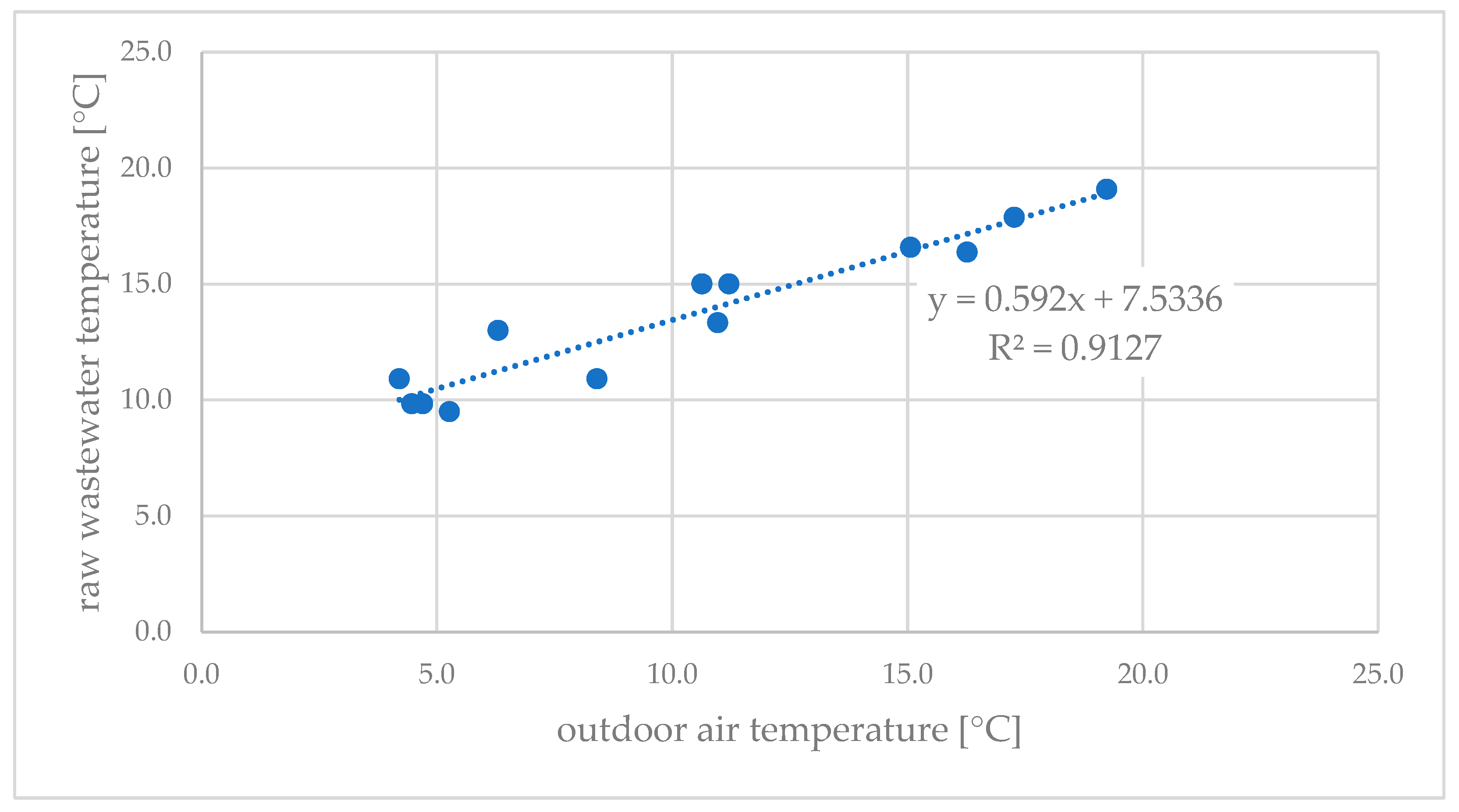
The relationship between the monthly average outdoor air temperature and the temperature of raw wastewater flowing into the treatment plant is shown in Figure 3. There is a strong correlation between outdoor temperature and wastewater temperature. The lowest average raw wastewater temperature occurs in February (9.5 °C). This indicates the possibility of heat recovery from influent wastewater even in the coldest seasons of the year. It is important to remember not to excessively inhibit or stop the processes of biological treatment of wastewater below a certain temperature (below 5 °C).
Wastewater flowing into the plant is characterized by relatively high temperature and volume flux, which predisposes it to be a stable source of waste heat for the heat pump. The application of a heat pump as a low-emission, highly efficient heating device is consistent with the EU climate policy and fits well with the idea of sustainable development.
2.4. Calculation Model
The heat flux recoverable from wastewater () depends on the amount and specific heat of the wastewater and the wastewater temperature reduction in the heat recovery exchanger:
where:
ρ—wastewater density, assumed as 1000 (kg/m3),
—wastewater volume flux, (m3/s),
cw—wastewater specific heat, assumed as 4.19 (kJ/kgK),
ΔT—temperature difference of wastewater at the inlet and outlet of the heat recovery exchanger (K).
As a result of heat recovery, the temperature of wastewater will change. The resulting temperature difference (ΔT) was calculated with the following limitations: (1) in order to maintain a safety margin for the proper process of wastewater treatment, a minimum wastewater temperature of 8 °C was assumed; (2) in the case of heat discharge, the upper limit of the temperature to which the wastewater can be heated cannot exceed 30–35 °C, due to the rapid decline and decay of the treatment processes [37].
As part of the analysis, the following locations for installing the heat recovery installation at the Mokrawica WWTP will be considered: sand box, aeration chamber, secondary sedimentation tank, and treated sewage disposal (Figure 1).
The recovered heat can be used for the plant’s own needs, e.g., heating of the building and hot water preparation, heating of wastewater at the beginning of the biological treatment process, e.g., in the sand box or aeration chamber, as well as for air conditioning of the office buildings.
In the case of utilizing the heat recovered from wastewater for the plant’s own needs, it was assumed that this process would be carried out by a heat pump. Knowing the coefficient of performance (COP) of the unit and the heat capacity of one of the heat sources, the other one can be determined from the formula:
where:
Qc—heat output of the heat source (cooling capacity) (kW),
Qh—heat output of the heat sink (heating capacity) (kW),
COP—coefficient of performance (-).
Depending on the heat pump’s operating parameters, the power required for running the compressor in order to meet the heating demand differs. The COP can be calculated as:
where:
Qh—heat supplied by a heat pump (W),
P—compressor power (W).
Determining COP from Equation (3) requires thermodynamic simulations of a heat pump cycle at various operating conditions. The performance prediction of different working fluids can be obtained from system modeling and experiments [48]. Determination was performed with the use of REFPROP software [58]. Basic input data for the calculation of the heat pump’s COP include evaporation and condensation temperatures, superheating of vapour refrigerant, subcooling of liquid refrigerant, isentropic efficiency of a compressor, type of working fluid (refrigerant properties), and type of vapour compression cycle. Full system modeling or detailed experimentation are costly and time-consuming.
Based on a comparison of 155 case studies on the use of industrial heat pumps, Schlosser et al. [59] proposed an empirical model to determine, with high accuracy, the COP of a heat pump depending only on the values of the heat sink temperature and the temperature difference of a heat source and sink over a wide range of variation of these parameters. The COP is determined from the formula [59]:
where:
ΔTlift—temperature difference between the heat source and heat sink (K),
Th –heat sink temperature (K),
a, b, c, d—regression coefficients (-), assumed as a = 1.4480 × 10¹², b = 88.730, c = −4.9460, d = 0.0000—as for standard and high-temperature heat pumps with HFC or HFO refrigerant [59].
Heat can be transferred from wastewater to the heat pump with a direct expansion heat exchanger (direct system) or a secondary fluid circuit (indirect system). The latter is less efficient due to additional heat exchange and temperature difference between the refrigerant and secondary fluid, as well as extra pump work required in the secondary circuit. To calculate COP from Equation (4) for the indirect system, an additional 5 K difference between heat transfer fluid and wastewater temperature must be taken into account [59].
This method of determining COP is convenient for use in general analyses because it is based on existing systems and does not require additional calculations of the heat pump thermodynamic cycle at various operating conditions.
3. Results and Discussion
3.1. Evaluation of the Heat Recovery Potential
Based on Equation (1), a general function of the available waste heat resource was determined as a function of the wastewater flow rate and temperature reduction rate. The results are illustrated in Figure 4 and are in line with the available literature [45].
The available heat resource increases with the increase in wastewater flow and the temperature difference. Knowing the heat demand, the expected decrease in wastewater temperature due to heat recovery can be determined. Knowing how much the wastewater can be cooled determines the resources available for use.
The results can also be used to estimate the amount of heat that can be discharged to wastewater, e.g., from the air conditioning system. In this case, ΔT will mean the difference between the temperature to which the wastewater is heated as a result of transferring heat to it, and the temperature of the wastewater.
During the analyses, it is important to remember the limits of wastewater temperature changes due to the processes of biological treatment taking place in the WWTP. Wastewater temperatures recommended in Polish conditions should not exceed the range of 5–35 °C [36,37].
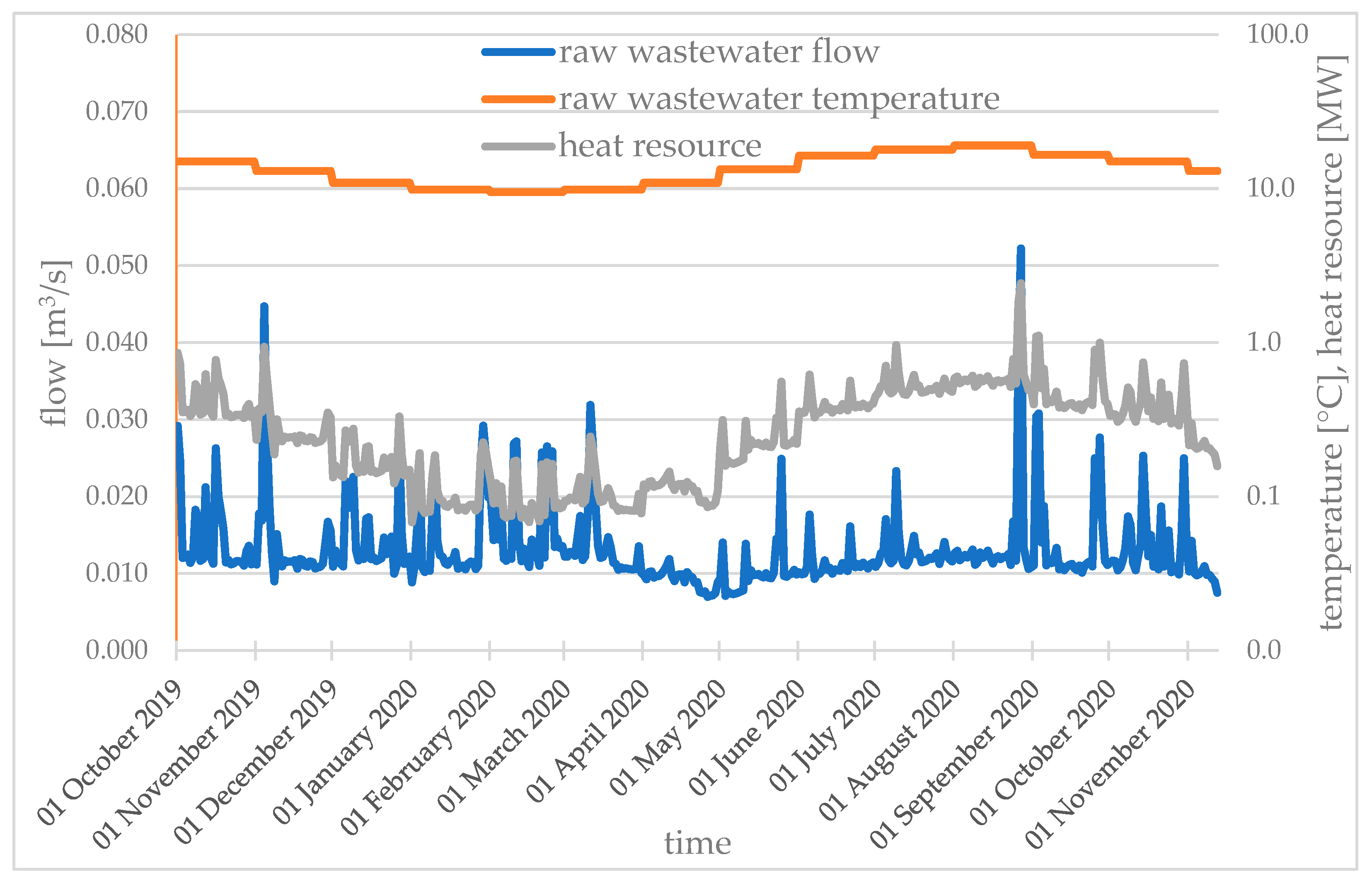
Figure 5 and Figure 6 show measurement data for the flow and temperature of raw and treated wastewater, respectively, at the inlet and outlet of the treatment plant. Based on that information, the available heat resource was determined from Equation (1). The minimum value of the temperature to which the wastewater can be cooled as a result of heat recovery was assumed as 8 °C.
A large fluctuation of instantaneous wastewater flow and proportionally related variation of heat recovery potential is observed. Such large deviations from the average value may result from the occurrence of periodic precipitation or be due to measurement error. The trend line of the average heat resource is similar to that of the wastewater temperature, but with a higher amplitude. The average flow of influent is between 33.1 m3/h (in April 2020) and 57.5 m3/h (in February 2020). The lowest mean wastewater temperature recorded occurred in winter (February) and was 9.5 °C. The average values of heat recovery potential are about 0.31 MW and 0.45 MW, with a minimum of 0.068 MW and 0.058 MW for raw and treated wastewater, respectively. Considering the possible reduction in exchanger performance (up to 50% [34]) as a result of surface fouling, it is advisable to introduce an appropriate safety factor and/or a heat exchanger that allows for periodic cleaning of its surface. In practice, the heat recovery potential of treated wastewater is higher due to the absence of temperature limitations on the wastewater discharge.
3.2. Analysis of Selected Solution Alternatives
Thermodynamic simulations of a heat pump cycle were performed for different refrigerants. The COP was calculated according to Equation (3) with the following assumptions. The heat sink temperature level was considered to be at a constant level required to supply heating. Depending on the type of heat exchanger and transfer system (direct, indirect), the temperature difference between the wastewater and evaporating refrigerant will vary, typically in the range of 5–10 K. A value of 8 K was assumed in the calculations. The values of superheating, subcooling, and isentropic efficiency in a single-stage heat pump cycle were adopted as typical for the operation of a compact unit with the heat source and heat sink at a constant temperature. Depending on the operating parameters, those values might vary, and could be optimized [60,61,62]. The operating parameters of the heat pump used in the analysis are summarized in Table 2.
The results of thermodynamic simulations of heat pump cycles with different refrigerants are shown in Figure 7. The COP varies depending on the refrigerant and month (wastewater temperature in a given period of time). The lowest values occur in winter and the highest in summer. Absolute differences in the COP values are up to ΔCOP = 0.5–0.64 for selected refrigerants. This shows that the choice of refrigerant used in the heat pump has a significant impact on the ratio of heating capacity to compressor power input.
Additionally, the COP calculated from Equation (4) was also shown in Figure 7. The obtained results are within the average value of COP for different refrigerants. Hence, Equation (4) can be used as a general prediction of the COP variability for further analysis.
Heat recovery was considered for the following locations along the technological process of the Mokrawica WWTP (Figure 1): (A) sand box, (B) aeration chamber, (C) secondary sedimentation tank, and (D) treated sewage disposal. In these places, the heat recovery potential (Qhr) was determined from Equation (1). Calculations were made for the minimum values of wastewater temperature (tmin) and flow (Vmin) recorded in the considered period. It was assumed that as a result of recovery, the wastewater can be cooled down to 8 °C. The input data and results are in Table 3.
Depending on the choice of heat recovery location, between 57.9 kW and 93.8 kW of heat can be obtained.
Similarly, the potential for heat removal from an air-conditioning system was determined. Considering that wastewater can only be heated to 25 °C in summer, between 185.9 kW and 228.2 kW of heat can be transferred to the wastewater. The results are shown in Table 4. A greater amount of heat can be transferred to wastewater in the summer, compared to the amount that can be recovered in winter, which results from the greater temperature difference (ΔT) between the actual (tmax) and allowed temperature (25 °C).
The heating and cooling demand of the building is 60 kW and 120 kW, respectively [55]. When analysing the possibility of heating wastewater to the temperature optimal for biological processes in winter, the target temperature of 20 °C was adopted. Data for calculations and results are presented in Table 5. The capacity required for the heating and cooling needs inside the facility range from 60 to more than 400 kW. The demand for central heating, hot water, and air-conditioning is much lower than for optimizing the conditions of the biological process.
The capacity of the heat pump’s source (Qc) and sink (Qh) was estimated using Equation (2), based on the required heating and cooling demand (Table 5) and the COP determined from relation (4). It was assumed that the heat pump will provide a temperature of 50 °C for heating and hot water of the building (case 1, Table 6) and 20 °C for heating wastewater in the sand box and aeration chamber (cases 2 and 3, Table 6) by recovering heat from wastewater at 9.5 °C. The air-conditioning system (case 4, Table 6) will produce chilled water at 7 °C and transfer the heat taken from the building to the wastewater at 20 °C. Direct expansion (direct) and indirect (secondary fluid circuit) heat transfer systems were considered (cases a and b, Table 6), with an additional 5 K temperature difference (ΔTlift) between heat transfer fluid and wastewater for the indirect system. The heat source (tc) and heat sink (th) temperatures and the results are summarized in Table 6.
Calculation results indicate that 43–45 kW of heat must be recovered from wastewater for heating and hot water, depending on the choice of direct or indirect system. In order to heat the wastewater at the beginning of the biological treatment process, it is necessary to recover about 349–356 kW from the treated wastewater. The heat transferred to wastewater from the air-conditioning system amounts to 138–141 kW. Indirect heat transfer systems have lower COP values than direct ones, which will result in higher energy consumption. The heat pump COP is within the range reported in Table 1 for heating and domestic hot water. A small temperature difference between the heat source and heat sink for other purposes results in high COP.
In the investigated treatment plant there are small heat resources compared to the installations listed in Table 1. However, a comparison of determined waste heat resources (cases A–D) with needs (cases 1–4), indicates the possibility of full realization of cases 1 and 4. The partial realization of cases 2 and 3 requires further analysis.
4. Conclusions
Heat recovery from wastewater is an interesting and current topic. The paper explores the potential of heat recovery from a WWTP by integrating a heat pump system, presented on the example of the Mokrawica wastewater treatment plant, located in the West Pomeranian region of Poland. The proposed methodology for estimating heat resources and the required heat capacities and COP of a heat pump is based on only three parameters: wastewater volumetric flow, wastewater temperature, and the required temperature for heating or air-conditioning purposes. The heat recovery potential is determined for different stages of wastewater treatment in the studied WWTP. The results also indicate what cooling capacities can be provided by the heat pump for air-conditioning in the summer. The amount of heat that could be supplied by a heat pump under existing conditions over a year for purpose of heating and domestic hot water, as well as for preheating wastewater to improve biological treatment processes in the winter season was also evaluated.
Author Contributions
Conceptualization, T.Ł. and A.G.; methodology, T.Ł., W.T., D.L.-P., A.G.; formal analysis, T.Ł.; resources, T.Ł., W.T., D.L.-P., A.G.; writing—original draft preparation, T.Ł., W.T., D.L.-P., A.G.; writing—review and editing, T.Ł., W.T., D.L.-P., A.G.; visualization, T.Ł.; supervision, A.G.; project administration, D.L.-P.; All authors have read and agreed to the published version of the manuscript.
Funding
This research received no external funding.
Data Availability Statement
Not applicable.
Conflicts of Interest
The authors declare no conflict of interest.
References
- Hervás-Blasco, E.; Navarro-Peris, E.; Corberán, J.M. Closing the residential energy loop: Grey-water heat recovery system for domestic hot water production based on heat pumps. Energy Build. 2020, 216, 109962. [Google Scholar] [CrossRef]
- McNabola, A.; Shields, K. Efficient drain water heat recovery in horizontal domestic shower drains. Energy Build. 2013, 59, 44–49. [Google Scholar] [CrossRef]
- Torras, S.; Oliet, C.; Rigola, J.; Oliva, A. Drain water heat recovery storage-type unit for residential housing. Appl. Therm. Eng. 2016, 103, 670–683. [Google Scholar] [CrossRef] [Green Version]
- Farman Ali, S.; Gillich, A. The potential of the heat recovery from urban sewage wastewater for use in residential and commercial buildings. In Proceedings of the Cibse Ashrae Technical Symposium, Glasgow, UK, 16–17 April 2020. [Google Scholar]
- Li, H.; He, W.; Feng, G.; Qin, Y. Design of New Type Waste Gas/Wastewater Dual—Source Heat Pump Energy Cascade Recovery System in Campus Bath. Procedia Eng. 2017, 205, 3328–3333. [Google Scholar] [CrossRef]
- Baek, N.C.; Shin, U.C.; Yoon, J.H. A study on the design and analysis of a heat pump heating system using wastewater as a heat source. Sol. Energy 2005, 78, 427–440. [Google Scholar] [CrossRef]
- Hepbasli, A.; Biyik, E.; Ekren, O.; Gunerhan, H.; Araz, M. A key review of wastewater source heat pump (WWSHP) systems. Energy Convers. Manag. 2014, 88, 700–722. [Google Scholar] [CrossRef]
- Kahraman, A.; Çelebi, A. Investigation of the Performance of a Heat Pump Using Waste Water as a Heat Source. Energies 2009, 2, 697–713. [Google Scholar] [CrossRef]
- Meggers, F.; Leibundgut, H. The potential of wastewater heat and exergy: Decentralized high-temperature recovery with a heat pump. Energy Build. 2011, 43, 879–886. [Google Scholar] [CrossRef]
- Đurđević, D.; Balić, D.; Franković, B. Wastewater heat utilization through heat pumps: The case study of City of Rijeka. J. Clean. Prod. 2019, 231, 207–213. [Google Scholar] [CrossRef]
- Zhao, X.L.; Fu, L.; Zhang, S.G.; Jiang, Y.; Lai, Z.L. Study of the performance of an urban original source heat pump system. Energy Convers. Manag. 2010, 51, 765–770. [Google Scholar] [CrossRef]
- Wehbi, Z.; Taher, R.; Faraj, J.; Ramadan, M.; Castelain, C.; Khaled, M. A short review of recent studies on wastewater heat recovery systems: Types and applications. Energy Rep. 2022, 8 (Suppl. S9), 896–907. [Google Scholar] [CrossRef]
- Bohra, V.; Ahamad, K.U.; Kela, A.; Vaghela, G.; Sharma, A.; Deka, B.J. Chapter 2—Energy and resources recovery from wastewater treatment systems. In Clean Energy and Resource Recovery; An, A., Tyagi, V., Kumar, M., Cetecioglu, Z., Eds.; Elsevier: Amsterdam, The Netherlands, 2022; pp. 17–36. [Google Scholar] [CrossRef]
- Reiners, T.; Gross, M.; Altieri, L.; Wagner, H.-J.; Bertsch, V. Heat pump efficiency in fifth generation ultra-low temperature district heating networks using a wastewater heat source. Energy 2021, 236, 121318. [Google Scholar] [CrossRef]
- Postrioti, L.; Baldinelli, G.; Bianchi, F.; Buitoni, G.; Di Maria, F.; Asdrubali, F. An experimental setup for the analysis of an energy recovery system from wastewater for heat pumps in civil buildings. Appl. Therm. Eng. 2016, 102, 961–971. [Google Scholar] [CrossRef]
- Chae, K.-J.; Ren, X. Flexible and stable heat energy recovery from municipal wastewater treatment plants using a fixed-inverter hybrid heat pump system. Appl. Energy 2016, 179, 565–574. [Google Scholar] [CrossRef]
- Cipolla, S.S.; Maglionico, M. Heat Recovery from Urban Wastewater: Analysis of the Variability of Flow Rate and Temperature in the Sewer of Bologna, Italy. Energy Procedia 2014, 45, 288–297. [Google Scholar] [CrossRef] [Green Version]
- Liangdong, M.; Tixiu, R.; Tianjiao, Z.; Tianyi, Z.; Jili, Z. Experimental study on effect of operating parameters on performance of serially cascaded wastewater source heat pump. J. Build. Eng. 2020, 32, 101458. [Google Scholar] [CrossRef]
- Cipolla, S.S.; Maglionico, M. Heat recovery from urban wastewater: Analysis of the variability of flow rate and temperature. Energy Build. 2014, 69, 122–130. [Google Scholar] [CrossRef]
- Somogyi, V.; Sebestyén, V.; Domokos, E. Assessment of wastewater heat potential for district heating in Hungary. Energy 2018, 163, 712–721. [Google Scholar] [CrossRef]
- Todorović, D.; Tomić, M.; Bojanić, R.; Bajatović, D.; Anđelković, A.S. A comparative analysis of a heat pump application with grey wastewater source for domestic hot water preparation in hotels. J. Therm. Anal. Calorim. 2020, 141, 559–572. [Google Scholar] [CrossRef]
- Ninikas, K.; Hytiris, N.; Emmanuel, R.; Aaen, B. Recovery and Valorisation of Energy from Wastewater Using a Water Source Heat Pump at the Glasgow Subway: Potential for Similar Underground Environments. Resources 2019, 8, 169. [Google Scholar] [CrossRef] [Green Version]
- Wu, Y.; Jiang, Y.; Gao, B.; Liu, Z.; Liu, J. Thermodynamic analysis on an instantaneous water heating system of shower wastewater source heat pump. J. Water Reuse Desalin. 2018, 8, 404–411. [Google Scholar] [CrossRef] [Green Version]
- Qin, N.; Hao, P.Z. The operation characteristics of sewage source heat pump system and the analysis of its thermal economic benefits. Appl. Therm. Eng. 2017, 124, 1083–1089. [Google Scholar] [CrossRef]
- Neugebauer, G.; Kretschmer, F.; Kollmann, R.; Narodoslawsky, M.; Ertl, T.; Stoeglehner, G. Mapping Thermal Energy Resource Potentials from Wastewater Treatment Plants. Sustainability 2015, 7, 12988–13010. [Google Scholar] [CrossRef] [Green Version]
- Liu, Z.; Ma, L.; Zhang, J. Application of a heat pump system using untreated urban sewage as a heat source. Appl. Therm. Eng. 2014, 62, 747–757. [Google Scholar] [CrossRef]
- Mi, P.; Ma, L.; Zhang, J. Integrated optimization study of hot water supply system with multi-heat-source for the public bath based on PVT heat pump and water source heat pump. Appl. Therm. Eng. 2020, 176, 115146. [Google Scholar] [CrossRef]
- Qiang, W.; Xiaoming, Z.; Xinqi, G.; Xu, C.; Meize, X. Experiments on the characteristics of a sewage water source heat pump system for heat recovery from bath waste. Appl. Therm. Eng. 2022, 204, 117956. [Google Scholar] [CrossRef]
- Gruber-Glatzl, W.; Brunner, C.; Meitz, S.; Schnitzer, H. From the Wastewater Treatment Plant to the Turnstiles of Urban Water and District Heating Networks. Front. Sustain. Cities 2020, 2, 523698. [Google Scholar] [CrossRef]
- Nagpal, H.; Spriet, J.; Krishna Murali, M.; McNabola, A. Heat Recovery from Wastewater—A Review of Available Resource. Water 2021, 13, 1274. [Google Scholar] [CrossRef]
- Shen, C.; Lei, Z.; Wang, Y.; Zhang, C.; Yao, Y. A review on the current research and application of wastewater source heat pumps in China. Therm. Sci. Eng. Prog. 2018, 6, 140–156. [Google Scholar] [CrossRef]
- Zhang, Q.; Nie, Q.; Liu, F.; Yin, C. Technology and Economic Analysis of Sewage Source Heat Pump Combined Type District Heating Method. Energy Procedia 2017, 142, 1312–1318. [Google Scholar] [CrossRef]
- Shen, C.; Jiang, Y.; Yao, Y.; Deng, S. Experimental performance evaluation of a novel dry-expansion evaporator with defouling function in a wastewater source heat pump. Appl. Energy 2012, 95, 202–209. [Google Scholar] [CrossRef]
- Słyś, D.; Kordana, S. Waste Heat Recovery in Installations and Sewage Systems; KaBe s.c. Publishing House and Book Trade: Krosno, Poland, 2013. [Google Scholar]
- Kretschmer, F.; Hrdy, B.; Neugebauer, G.; Stoeglehner, G. Wastewater Treatment Plants as Local Thermal Power Stations—Modifying Internal Heat Supply for Covering External Heat Demand. Processes 2021, 9, 1981. [Google Scholar] [CrossRef]
- Dymaczewski, Z.; Oleszkiewicz, J.A.; Sozański, M.M. Wastewater Treatment Plant Operator’s Guide; PZITS O/Poznań: Poznań, Poland, 1997. [Google Scholar]
- Sadecka, Z. Basics of Biological Wastewater Treatment; Seidel-Przywecki Sp z o.o.: Warsaw, Poland, 2010. [Google Scholar]
- Elias-Maxil, J.A.; van der Hoek, J.P.; Hofman, J.; Rietveld, L. Energy in the urban water cycle: Actions to reduce the total expenditure of fossil fuels with emphasis on heat reclamation from urban water. Renew. Sustain. Energy Rev. 2014, 30, 808–820. [Google Scholar] [CrossRef] [Green Version]
- Imran, M.; Hasan, S.; Izharul, R.; Farooqi, H.; Basheer, F. Aeration control strategy design based on dissolved oxygen and redox potential profiles for nitrogen and phosphorus removal from sewage in a sequencing batch reactor. J. Water Process Eng. 2022, 50, 103259. [Google Scholar] [CrossRef]
- Zhang, K.; Yang, S.; Luo, H.; Chen, J.; An, X.; Chen, W.; Zhang, X. Enhancement of nitrogen removal and energy recovery from low C/N ratio sewage by multi-electrode electrochemical technology and tidal flow via siphon aeration. Chemosphere 2022, 299, 134376. [Google Scholar] [CrossRef]
- Wendling, A.C.; Oliveira JG, B.; Jenzura, N.T.; Lopes, D.D.; Damianovic MH, R.Z.; Barana, A.C. Structured-bed reactor with intermittent aeration and recirculation (SBRRIA) for treating UASB effluent combined with raw sewage. Int. J. Environ. Sci. Technol. 2022, 1–8. [Google Scholar] [CrossRef]
- Zeng, W.; Guo, Z.; Zhang, H.; Wang, J.; Gao, X.; Shen, Y.; Gadow, S.I. Fuzzy inference-based control and decision system for precise aeration of sewage treatment process. Electron. Lett. 2021, 57, 112–115. [Google Scholar] [CrossRef]
- Badeti, U.; Pathak, N.K.; Volpin, F.; Dorji, U.; Freguia, S.; Shon, H.K.; Phuntsho, S. Impact of source-separation of urine on effluent quality, energy consumption and greenhouse gas emissions of a decentralized wastewater treatment plant. Process Safery Environ. Prot. 2021, 150, 298–304. [Google Scholar] [CrossRef]
- Cecconet, D.; Racek, J.; Callegari, A.; Hlavinek, P. Energy recovery from wastewater: A study on heating and cooling of a multipurpose building with sewage-reclaimed heat energy. Sustainability 2020, 12, 116. [Google Scholar] [CrossRef]
- Kretschmer, F.; Simperler, L.; Ertl, T. Analysing wastewater temperature development in a sewer system as a basis for the evaluation of wastewater heat recovery potentials. Energy Build. 2016, 128, 639–648. [Google Scholar] [CrossRef]
- Advanced Heat Pump Systems Using Urban Waste Heat Sewage Heat. Mitsubishi Heavy Industries Technical Review” Vol. 52, No. 4/2015. Available online: https://www.mhi.co.jp/technology/review/pdf/e524/e524080.pdf (accessed on 9 October 2021).
- Averfalk, H.; Ingvarsson, P.; Persson, U.; Gong, M.; Werner, S. Large heat pumps in Swedish district heating systems. Renew. Sustain. Energy Rev. 2017, 79, 1275–1284. [Google Scholar] [CrossRef]
- Yan, H.; Ding, L.; Sheng, B.; Dong, X.; Zhao, Y.; Zhong, Q.; Gong, W.; Gong, M.; Guo, H.; Shen, J. Performance prediction of HFC, HC, HFO and HCFO working fluids for high temperature water source heat pumps. Appl. Therm. Eng. 2021, 185, 116324. [Google Scholar] [CrossRef]
- Khanlari, A.; Sözen, A.; Sahin, B.; di Nicola, G.; Afshari, F. Experimental investigation on using building shower drain water as a heat source for heat pump systems. Energy Sources Part A Recovery Util. Environ. Eff. 2020, 1–13. [Google Scholar] [CrossRef]
- Zhang, Q.; Wang, Z.; Yin, C.; Nie, Q.; Jin, L. Field Test Analysis of a Urban Sewage Source Heat Pump System Performance. Energy Procedia 2017, 143, 131–136. [Google Scholar] [CrossRef]
- Żogała, A.; Darul, H.; Głodniok, M.; Zawartka, P. Wastewater as a source of waste heat—A case study. Inż. Ekol. 2016, 49, 208–212. [Google Scholar] [CrossRef] [Green Version]
- David, A.; Mathiesen, B.V.; Averfalk, H.; Werner, S.; Lund, H. Heat Roadmap Europe: Large-Scale Electric Heat Pumps in District Heating Systems. Energies 2017, 10, 578. [Google Scholar] [CrossRef] [Green Version]
- Song, Y.; Yao, Y.; Ma, Z.; Na, W. Study of Performance of Heat Pump Usage in Sewage Treatment and Fouling Impact on System. In Proceedings of the Sixth International Conference for Enhanced Building Operations, Shenzen, China, 6–9 November 2006. [Google Scholar]
- Regulation of the Polish Minister of Maritime Economy and Inland Navigation of 12 July 2019 on Substances Particularly Harmful to the Aquatic Environment and the Conditions to Be Met When Introducing Sewage into Waters or into the Ground, as well as When Discharging Rainwater or Meltwater into Waters or to Water Devices. (Journal of Laws of the Republic of Poland 2019, Item 1311). Available online: https://isap.sejm.gov.pl/isap.nsf/download.xsp/WDU20190001311/O/D20191311.pdf (accessed on 8 November 2021).
- PGK (Kamień Pomorski, Poland). Technical Documentation of the Mokrawica Wastewater Treatment Plant. Unpublished Documentation.
- Jaworski, R.; Gadaj, P.; Suchorzewska, K.; Watoła, A.; Wojciechowska, K. Study of Conditions and Directions of Spatial Development of the Town and Commune of Kamień Pomorski; Municipal Office in Kamień Pomorski, Town Planning Services: Warszawa, Poland, 2013; Available online: https://mpzp.igeomap.pl/doc/kamienpomorski/kamienpom/00.pdf (accessed on 9 November 2021).
- IMGW Meteorological Data. Available online: https://danepubliczne.imgw.pl/ (accessed on 9 November 2021).
- Lemmon, E.; Huber, M.L.; Mclinden, M.O. NIST Standard Reference Database Reference Fluid Thermodynamic and Transport Properties-REFPROP, 9.1; National Institute of Standards and Technology: Gaithersburg, MD, USA, 2013. [Google Scholar]
- Schlosser, F.; Jesper, M.; Vogelsang, J.; Walmsley, T.G.; Arpagaus, C.; Hesselbach, J. Large scale heat pumps: Applications, performance, economic feasibility and industrial integration. Renew. Sustain. Energy Rev. 2020, 133, 110219. [Google Scholar] [CrossRef]
- Pitarch, M.; Hervas-Blasco, E.; Navarro-Peris, E.; Corberán, J.M. Exergy analysis on a heat pump working between a heat sink and a heat source of finite heat capacity rate. Int. J. Refrig. 2019, 99, 337–350. [Google Scholar] [CrossRef]
- Selbaş, R.; Kızılkan, Ö.; Şencan, A. Thermoeconomic optimization of subcooled and superheated vapor compression refrigeration cycle. Energy 2006, 31, 2108–2128. [Google Scholar] [CrossRef]
- Hervás-Blasco, E.; Navarro-Peris, E.; Barceló-Ruescas, F.; Corberán, J.M. Improved water to water heat pump design for low-temperature waste heat recovery based on subcooling control. Int. J. Refrig. 2019, 106, 374–383. [Google Scholar] [CrossRef]
Figure 1.
Operational diagram of the Mokrawica WWTP: 1. Wastewater inflow, 2. Screen, 3. Sand box, 4. Predenitrification/retention chamber, 5. Anaerobic chamber, 6. Anoxic chamber, 7. Transitional nitrification, 8. Aeration chamber, 9. Secondary sedimentation tank, 10. Treated sewage disposal; A, B, C, D—Proposed heat recovery location, F—flowmeter, T—temperature measurement.

Figure 2.
Wastewater flow and temperature variation during the year.

Figure 3.
Correlation between wastewater temperature and air temperature.

Figure 4.
Available waste heat resource.

Figure 5.
Heat recovery potential of raw wastewater.

Figure 6.
Potential for heat recovery from treated wastewater.

Figure 7.
COP variation of a heat pump with selected refrigerants over a year.


| City/Country | System Supplier | Arrangement | HP Capacity/COP | Purpose | Year |
|---|---|---|---|---|---|
| Southeast False Creek, BC, Canada | IWS Sewage SHARC | Raw wastewater, screened, passed to shell and tube heat exchanger | 2.7 MW | Heating + Hot water | 2010 |
| Wintower, Winterthur, Switzerland | Huber Technology RoWin | Raw wastewater, screened and passed to a collector with a heat exchanger | 1.5 MW, COP 5–6 | Heating + Hot water + Cooling | 2011 |
| Dietikon (Zürich), Switzerland | Huber Technology ThermWin | Raw wastewater, screened and passed to a collector with a heat exchanger | 4.0 MW COP 5,5 | Heating + Hot water NH3 supply 40 °C | 2018 |
| Sandvika, Oslo, Norwey | Friotherm AG | 10 °C raw wastewater, screened, passed to shell and tube heat exchanger | 2 × 6.5 MW + 2 × 4.5 MW, COP 3.10 | Heating R 134a supply 68 °C + Cooling | 1998 (2008) |
| Sköyen Vest, Oslo, Norwey | Hafslund Fjernvarme AS | 10 °C Raw wastewater, screened, passed to shell and tube heat exchanger | 28 MW, COP 2.8 | Heating R 134a supply 90 °C | 2005 (2008) |
| Budapest Military Hospital, Węgry | Thermowatt Ltd. | Raw wastewater screened and passed to a collector with a heat exchanger | 3.8 MW + 3.4 MW, COP 6–7 | Heating/Cooling | 2014 |
| Budapest Sewage Works, Hungry | Thermowatt Ltd. | Raw wastewater screened and passed to a collector with a heat exchanger | 1.23 MW, COP 4,5 | Heating/Cooling | 2012 |
| Postal office of Muelligen/Schliern, SwitzerlandDH | EWZ utility | 8 to 102C effluent pumped into an evaporator of HP | 5.5 MW | Heating + Cooling, uses NH3, hot water supply 65 °C | 2006 |
| Suomenoja Espoo, Finland | Fortum Energi | Effluent pumped into an evaporator of HP | 2 × 20 MW + 2 × 14.5 MW, COP 3.0 | Heating + Hot water | 2014 |
| Katri Vala, Helsinki, Finland | Friotherm AG | 10 °C effluent pumped into an evaporator of HP | 3 × 30 MW + 2 × 30 MW, COP 3.5 | Heating + Cooling, uses R 134a, hot water supply 88 °C | 2006 |
| Kakola, Turku, Finland | Friotherm AG | 10 °C effluent pumped into an evaporator of HP | 2 × 10 MW + 2 × 30 MW, COP 3.3 | Heating + Cooling, uses R 134a, hot water supply 78 °C | 2006 |
| Ryaverket, Gothenburg, Sweden | Gӧteborg Energi | Effluent pumped into an evaporator of HP | 2 × 50 MW + 2 × 30 MW, COP 3 | Heating + Hot water | 2009 |
| Hammarby Stockholm, Sweden | Fortum Energi | Effluent pumped into an evaporator of HP | 5 HP producing a total of 131 MW, COP 3.0 | Heating + Hot water | 1986–1991–1997 |
| Lund, Sweden | Lund Energi | 8 to 16 °C effluent pumped into an evaporator of HP | 1 × 13 MW + 2 × 40 MW, COP 3.3 | Heating + Hot water + Cooling uses R-134a, hot water supply 80 to 90 °C | 1984 (2003) |
| Helsingborg, Sweden | - | Sewage water | 1 × 27 MW, COP 3.0 | Heating + Hot water + Cooling | 1996 |
| Kalundborg Denmark | Kalundborg Forsyning A/S | 20 °C effluent pumped into an evaporator of HP | 10 MW, | Kalundborg Denmark | 2017 |
| Lillestrøm, Norway | - | Sewage water | 4.3 MW COP | Heating + Hot water + Cooling | 2003 |
| Harbin, China | - | Recovery heat from sewage treated into the feedwater stream | Cooling capacity—580 kW COP 4.2 Heating capacity 714 kW | Heating of untreated sewage | - |
| Grudziądz, Poland | - | Sewage treated | 2 × 82.6 kW COP 4.0 | Heating + Hot water | 2002 |
| Dziarny, Poland | - | Sewage from the secondary settling tank | - | drying of sewage sludge | 2006 |
Table 2.
Parameters for a single-stage heat pump cycle.
| Parameter | Unit | Value |
|---|---|---|
| Evaporation temperature | °C | raw wastewater temperature −8 K |
| Condensation temperature | °C | 55 |
| Superheating of vapour at the evaporator outlet | K | 4 |
| Subcooling of liquid at the condenser outlet | K | 2 |
| Compressor isentropic efficiency | - | 0.7 |
Table 3.
Results of calculations of the heat recovery potential from wastewater at different locations at the treatment plant.
Table 3.
Results of calculations of the heat recovery potential from wastewater at different locations at the treatment plant.
| Case | Heat Recovery Location | Vmin (m3/h) | tmin (°C) | ΔT (K) | Qhr (kW) |
|---|---|---|---|---|---|
| A | Sand box | 33.1 | 9.5 | 1.5 | 57.9 |
| B | Aeration chamber | 33.1 | 9.5 | 1.5 | 57.9 |
| C | Secondary sedimentation tank | 53.8 | 9.5 | 1.5 | 93.8 |
| D | Treated sewage disposal | 44.4 | 9.5 | 1.5 | 77.4 |
Table 4.
Results of calculating the potential for heat discharge to wastewater at different locations at the treatment plant during summer.
Table 4.
Results of calculating the potential for heat discharge to wastewater at different locations at the treatment plant during summer.
| Case | Heat Rejection Location | Vmin (m3/h) | tmax (°C) | ΔT (K) | Qhr (kW) |
|---|---|---|---|---|---|
| A | Sand box/Anaerobic chamber | 33.1 | 19.1 | 5.9 | 228.2 |
| B | Aeration chamber | 33.1 | 19.2 | 5.8 | 223.7 |
| C | Secondary sedimentation tank | 53.8 | 21.4 | 3.6 | 225.2 |
| D | Treated sewage disposal | 44.4 | 21.4 | 3.6 | 185.9 |
Table 5.
The required heating and cooling capacity at different locations at the treatment plant.
| Case | Location | Vmin (m3/h) | tmin (°C) | ΔT (K) | Qh (kW) |
|---|---|---|---|---|---|
| 1 | Heating and hot water | - | - | - | 60 |
| 2 | Sand box | 33.1 | 9.5 | 10.5 | 405 |
| 3 | Aeration chamber | 33.1 | 9.5 | 10.5 | 405 |
| Vmin (m3/h) | tmin (°C) | ΔT (K) | Qc (kW) | ||
| 4 | Air-conditioning | - | - | - | 120 |
Table 6.
Calculation results for the required capacity of the heat pump’s heat source and sink.
| Case | Heat Transfer System | Qh (kW) | th (°C) | tc (°C) | ΔTlift (K) | COP | Qc (kW) |
|---|---|---|---|---|---|---|---|
| 1a | direct | 60 | 50 | 9.5 | 40.5 | 3.94 | 44.8 |
| 1b | indirect | 60 | 55 | 9.5 | 45.5 | 3.52 | 43.0 |
| 2a, 3a | direct | 405 | 20 | 9.5 | 10.5 | 8.19 | 355.6 |
| 2b, 3b | indirect | 405 | 25 | 9.5 | 15.5 | 7.19 | 348.7 |
| Qc (kW) | th (°C) | tc (°C) | ΔTlift (K) | COP | Qh (kW) | ||
| 4a | direct | 120 | 20 | 7 | 13 | 7.67 | 138.0 |
| 4b | indirect | 120 | 25 | 7 | 18 | 6.75 | 140.9 |
Disclaimer/Publisher’s Note: The statements, opinions and data contained in all publications are solely those of the individual author(s) and contributor(s) and not of MDPI and/or the editor(s). MDPI and/or the editor(s) disclaim responsibility for any injury to people or property resulting from any ideas, methods, instructions or products referred to in the content. |
© 2022 by the authors. Licensee MDPI, Basel, Switzerland. This article is an open access article distributed under the terms and conditions of the Creative Commons Attribution (CC BY) license (https://creativecommons.org/licenses/by/4.0/).
Share and Cite
MDPI and ACS Style
Łokietek, T.; Tuchowski, W.; Leciej-Pirczewska, D.; Głowacka, A. Heat Recovery from a Wastewater Treatment Process—Case Study. Energies 2023, 16, 44. https://0-doi-org.brum.beds.ac.uk/10.3390/en16010044
AMA Style
Łokietek T, Tuchowski W, Leciej-Pirczewska D, Głowacka A. Heat Recovery from a Wastewater Treatment Process—Case Study. Energies. 2023; 16(1):44. https://0-doi-org.brum.beds.ac.uk/10.3390/en16010044
Chicago/Turabian StyleŁokietek, Tomasz, Wojciech Tuchowski, Dorota Leciej-Pirczewska, and Anna Głowacka. 2023. "Heat Recovery from a Wastewater Treatment Process—Case Study" Energies 16, no. 1: 44. https://0-doi-org.brum.beds.ac.uk/10.3390/en16010044
Note that from the first issue of 2016, this journal uses article numbers instead of page numbers. See further details here.