1. Introduction
In order to meet the growing demand for electricity, it is often necessary to relocate or rebuild overhead lines, especially in urban areas. To address this issue, overhead lines are gradually replaced by power cables that have higher reliability, lower maintenance, and reduced cost. More importantly, they are not limited by urban land restrictions. The new cables are often installed in tunnels and share the same tunnel with the existing lines in order to save on costs. Multiple cables are connected in parallel to enhance the transmission capacity. As the demand for urban loads grows, parallel cables are increasingly popular [
1,
2,
3]. Several projects have been implemented in China, e.g., the 220 kV double-circuit power cable between the Baoan Substation and Fenjin Substation (Anfen) in Shengzhen. Parallel cables are increasingly popular in electric power system, especially in urban areas [
4].
The use of cables connected in parallel will lead to many problems. For instance, it requires the structure of the power cable tunnel to be more complex, and the practice enhances the electromagnetic coupling between different cable loops. Although the parameters of power cables are almost the same, the current is often non-uniformly distributed amongst each individual circuit. This will give rise to additional power losses, overloading, etc. Although overloading is of great importance, it is usually undetectable since the current transformer often monitors the total line current instead of the individual circuit current. The impacts of load current, loop distance, line segment length, grounding resistance, and grounding method on the current distribution have been extensively discussed [
1,
5,
6,
7,
8,
9,
10,
11]. IEC 60287 presented a theoretical to predict the current distribution between parallel cables. A general current distribution prediction method is proposed for multiphase distribution systems, and the proposed method is experimentally validated [
7]. The analytical technique to predict the induced sheath voltage in metal sheaths of underground cables and overhead lines is overviewed in [
12]. The influences of harmonic content on the current distribution of cables connected in parallel are investigated in [
13]. The induced voltage of underground and rail cable are modelled in [
14] and [
15]. In order to deal with the current distribution installed on a metal tray, a general method for calculating the current distribution in a multiphase cable distribution system is developed [
16]. The skin and proximity phenomena cannot be neglected as doing so will affect the current density distribution in multi-strand cables significantly [
17].
When a high-voltage single-core power cable is under normal operation, the load current flowing cable core will generate an alternating magnetic field and induce voltage in the metal sheath through electromagnetic coupling. If the metal sheath and earth form a loop, i.e., the metal sheath is grounded at its ends, a circulating current will be produced along the sheath. This result not only generates power losses but also leads to a temperature rise and hence accelerates cable insulation ageing and affects cable capacity [
18,
19,
20]. In addition to the uneven cable core current distribution, the parallel cables may also lead to additional sheath circulating currents. The cross-connection sheaths produce a returning path of fault current and also restrain the overvoltage in a transient state. Various metal sheath connection methods are described in the associated IEEE guidelines or in technical report of the International Council on Large Electric Systems (CIGRE). The use of mathematical models to compute the induced voltage and current in cable sheaths is also recommended. The grounding method of cable sheaths at a single point or at both ends is normally applied to minimize the induced voltage along the cable sheaths in short-cable systems. However, little attention has been paid to the multi-cable case. There is a lack of research on the problems involved in laying three or even higher number of high-voltage cable loops. Several methods have been proposed to alleviate the circuiting current, such as the use of a series resistor or inductor. A computational model for predicting the circulating current along the metal sheath under the cross-connection condition is developed in [
21,
22]. However, the above methods mainly deal with the single-loop case, and do not take into account the coupling effect between cable loops. The effect of the core current of other adjacent cables is not included, and the existing methods are no longer applicable to multiple cables connected in parallel.
To limit the circulating current in a metal sheath, the cables generally adopt the grounding method of cross-connection. A finite element method for calculating the cable temperature field and cable capacity has been studied and the results show that an increase in sheath circulating current will lead to an increase in cable temperature. In this paper, the induced voltage of metal sheath is firstly divided into two components; then, three new connection methods for metal sheath are proposed. Their performance in suppressing the sheath circulating current is comprehensively discussed. This paper is organized as follows:
Section 2 is dedicated to the mathematical model of cables connected in parallel. A set of simulations have been performed in
Section 3. Three new methods for suppressing sheath circulating current are presented and compared with each other in
Section 4. The Conclusions are drawn in
Section 5.
2. Modeling of Power Cable Connected in Parallel
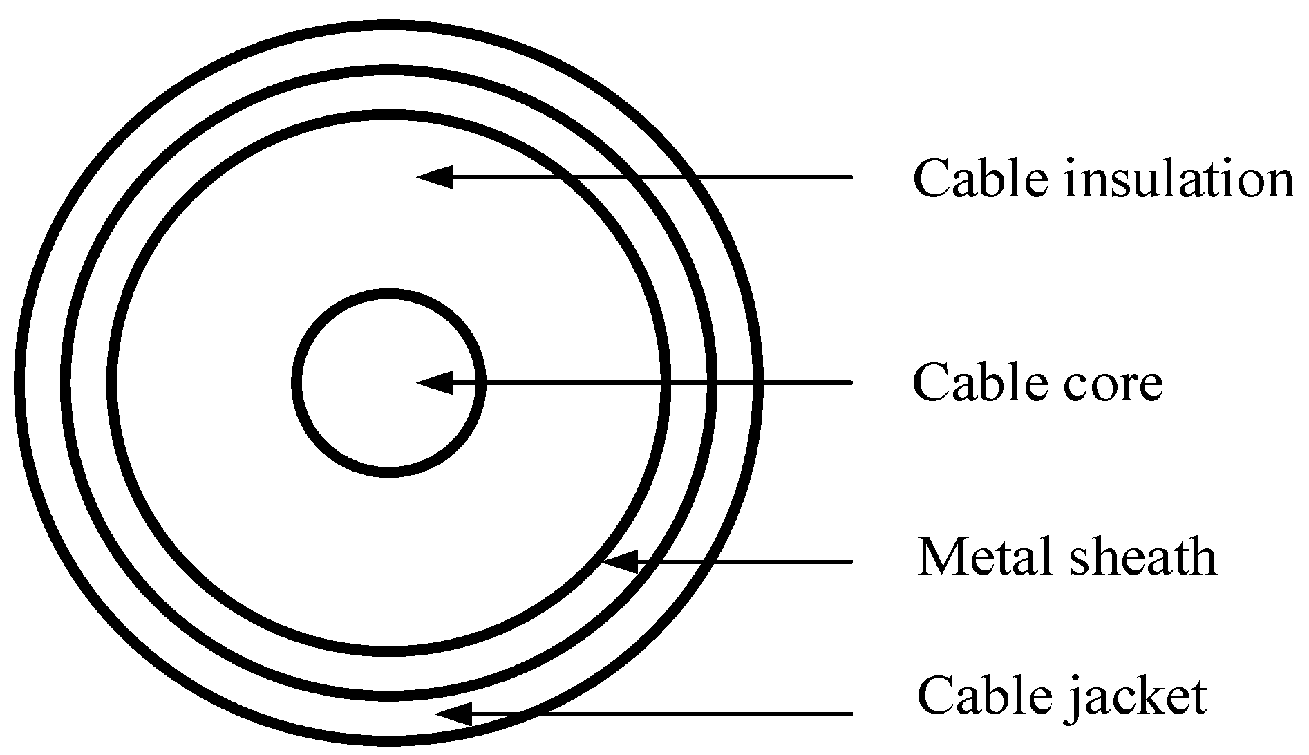
The schematic diagram for two sub-cables of phase A is depicted in
Figure 1. When the cable sheath is grounded in multiple points, a circuit is formed through the grounding point, and the current will flow through the metal sheath of cross-linked polyethylene power cable [
1,
16].
For the double-loop cable core and sheath, there are a total of 12 conductors. Based on the geometrical parameters of cable and the distances between two cables, the matrix
U, which represents the voltage drops of conductor, can be obtained by
where
I is the current matrix and
Z is the cable impedance matrix. The four types of elements of
Z can be calculated as follows.
The self-impedance of cable core [
6]:
The self-impedance of metal sheath [
6]:
The mutual impedance between cable core and metal sheath [
6]:
Other mutual impedance [
6]:
where
is the alternating current (AC) resistance of cable core,
is the AC resistance of sheath,
is the equivalent resistance of earth,
is the equivalent depth of earth,
is the geometric mean distance of core,
is the geometric radius of sheath and
is the spacing between the cables.
Taking the double circuits as an example, if the sheath is cross-connected, and the two ends are grounded, Equation (1) can be rewritten as:
where the 12-order impedance matrix Z is divided into 16 block matrices, each of which is a 3-order matrix, and the subscripts C1, S1, C2 and S2 of block matrix are the core of the 1st loop cable, the sheath of the 1st loop cable, the core of the 2nd loop cable, and the sheath of the 2nd loop cable, respectively.
According to Kirchhoff’s current law, the sum of each sub-cable core current is equal to the total current.
where
,
and
are the current of each phase, and
is the current of sub-cable
i in A phase.
and
are similar to
.
where
is the voltage drop of sub-cable
n in A phase. Obviously, the voltage drops of the sub-cable cores of each phase are all the same.
When the metal sheath is grounded at two ends, it is easy to obtain
where
,
and
are sheath circulating current of three phases, respectively, and
is the grounding resistance. Substituting Equation (9) into Equation (6) will yield six equations, and their matrix form is depicted as
where
is a third-order matrix, each element of which is equal to
.
Combined with Equations (7) and (8), the remaining six equations can be obtained as:
where
is a 3-order unit matrix and
is a 3-order zeros matrix. Equations (10) and (11) contain a total of 12 equations, and then the 12 current variables can be calculated.
ε is often used to characterize the uniformity of core current distribution in parallel cables, and its calculation formula is
where
Imax and
Imin are the maximum and minimum absolute value of core current in each sub-cable of parallel cables.
3. Simulation of Parallel Cable
As shown in
Figure 2, the rated voltage of power cables is 220 kV, the cross-sectional area is 2000 mm
2, and the total length is 1.5 km. The detailed geometric parameters of selected power cable YJLW03 are listed in
Table 1. Here, the soil resistivity is 100 Ω·m, the metal sheath of power cable is under cross-connection, and the total load current is set to 2000 A.
The arrangement of parallel cable is a key factor influencing the current distribution of cables and the circulating current of metal sheaths. Two common formations are introduced in IEEE Standard 575, i.e., the flat horizontal formation and the triangular formation. In terms of the cables connected in parallel, four typical arrangements are considered in this paper, and their structures are depicted in
Figure 3.
Phase spacing is the spacing between the geometric center of adjacent cables in a single loop. When double-loop cables are in a flat arrangement, the loop spacing is the spacing between the geometric center of the closest cables in a double loop, as shown in
Figure 3a,c. When double-loop cables are in a vertical arrangement, the loop spacing is the spacing between the brackets, as shown in
Figure 3b,d.
When the phase sequence of each loop is separate, there are various phase sequence combinations. Each arrangement of a phase sequence is written in the form of 123–456, as defined in
Figure 4.
As show in
Figure 5, the phase sequence of flat horizontal arrangement is ABC-cba; the flat vertical arrangement has two phase sequences, i.e., ABC-abc and ABC-cba; and the phase sequence of triangle horizontal arrangement is ABC-acb. All the double cable loops are symmetrical in space.
3.1. Phase Current Distribution
The single-loop cable containing only 3 cables has a total of
phase sequence combination. The double-loop cable is regarded as two single-loop cables. As shown in
Figure 4, it has
∗
= 36 phase sequence combinations. Due to the symmetry, only six phase sequences need to be calculated for a particular arrangement. When the phase sequence of the first loop is fixed as ABC and the phase sequence of the second loop is abc, bca, cab, acb, cba, and bac, respectively, the core current of parallel cable can be calculated. The simulation results of cable core current are listed in
Table 2 and
Table 3.
The non-uniformity coefficient of cable core current is depicted in
Figure 6. In the case of triangular vertical arrangement, the current is almost uniformly distributed between the six conductors. The maximum non-uniformity coefficient is only 1.0426 for abc and acb, and the minimum non-uniformity coefficient is 1.0186 for cab. In terms of flat vertical arrangement, the non-uniformity coefficient varies greatly. If the phase sequence of the second loop is acb or bac, both the non-uniformity coefficients are 1.2534. When the space between three-phase cables is very small, the electromagnetic coupling between the two loops connected in parallel is relatively small, and hence the mutual impedance is enhanced. However, the phase sequence has a greater impact on the current distribution under the flat vertical arrangement. From Equations (2)–(5), it can be seen that, if the mutual impedance of sub-cables of each phase with other cables is equal, the cable core current will be ideally symmetrical.
3.2. Circulating Current Distribution
If the cables are symmetrical in space, the core current of each cable is distributed in a balanced manner. Core current and sheath circulating current can be solved according to Equations (10) and (11). The phase sequences can affect the impedance matrix elements in Equations (10) and (11), causing core current and sheath circulating current to have different simulation results under different phase sequences. The sheath circulating current of parallel cables with different phase sequences under four grounding methods has been calculated. For each grounding method, the corresponding maximum and minimum sheath circulating current, which indicate the worst and best case for circulating current suppression, respectively, were selected from these simulation results. The maximum and minimum values of each arrangement of simulated sheath circulating currents are listed in
Table 4.
From
Table 4, it can be seen that the phase sequence has a great impact on the circulating current of metal sheath. The maximum value is about 6 times the size of the minimum value. In the case of triangle horizontal arrangement, the difference between the maximum value and the minimum value is the smallest.
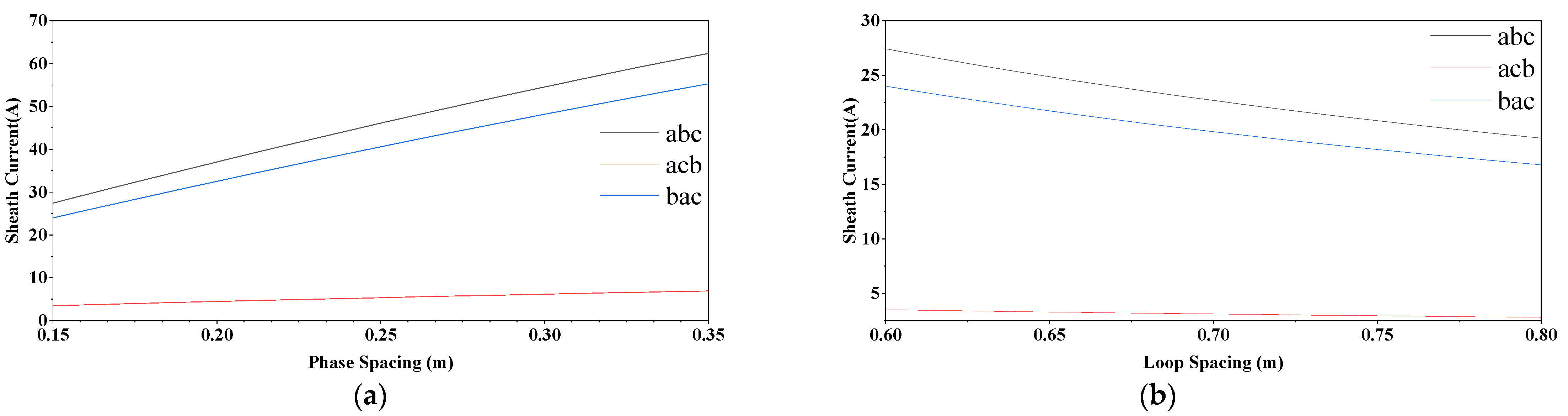
It can be seen from
Figure 3 that the cable spacing D in Equation (5) is decided by phase spacing and loop spacing. Therefore, the circulating current is influenced by phase spacing and loop spacing. The influence is computed, as plotted in
Figure 7. Here, parallel cables are under triangular horizontal arrangement and triangle vertical arrangement.
As the phase spacing increases, the sheath circulating current increases remarkably. As the loop spacing increases, the sheath circulating current declines remarkably. Generally, the loop spacing of triangular horizontal arrangement is larger than that of triangular vertical arrangement. The loop spacing of flat horizontal arrangement is large, meaning that it can effectively reduce the sheath circulating current. Clearly, phase spacing has a greater impact on the sheath circulating current than loop spacing.
4. Comparison of Methods for Suppressing Sheath Circulating Current
The topologies of four metal sheath connection methods are depicted in
Figure 8. Scheme 1 is the traditional cross-connection method. For scheme 1, each cable is divided into 6 equal sections and the two ends of the sheath are grounded. For scheme 2, each cable is divided into 6 equal sections, the metal sheaths of the double loops are crossconnected, and the two ends of the sheath are grounded. For scheme 3, each cable is divided into 3 equal sections, and the ends of the sheath from the same loop are linked. In order to reduce the number of cross-connected boxes, scheme 2 can be simplified to scheme 4, in which each cable is divided into 4 sections, and both its first section and fourth section take 1/3 of the total length, whereas both the second section and third section take 1/6 of the total length, and the sheaths of double loops are crossly connected.
When applied in the field test, scheme 2 and scheme 3 are created by changing the connection method of cross-connection box and grounding box, respectively.
The simulated core currents of parallel cable with flat and triangle vertical arrangements in scheme 2 are listed in
Table 5 and
Table 6, respectively. In the case of flat vertical arrangement, which occurs when the phase sequence is bac and acb, the maximum non-uniformity coefficient is 1.2341,. In the case of a triangular arrangement, which occurs when the phase sequence is abc and acb, it is 1.0985.
In addition, the core current is affected by the grounding methods, and the non-uniformity coefficient for parallel cable is plotted in
Figure 9.
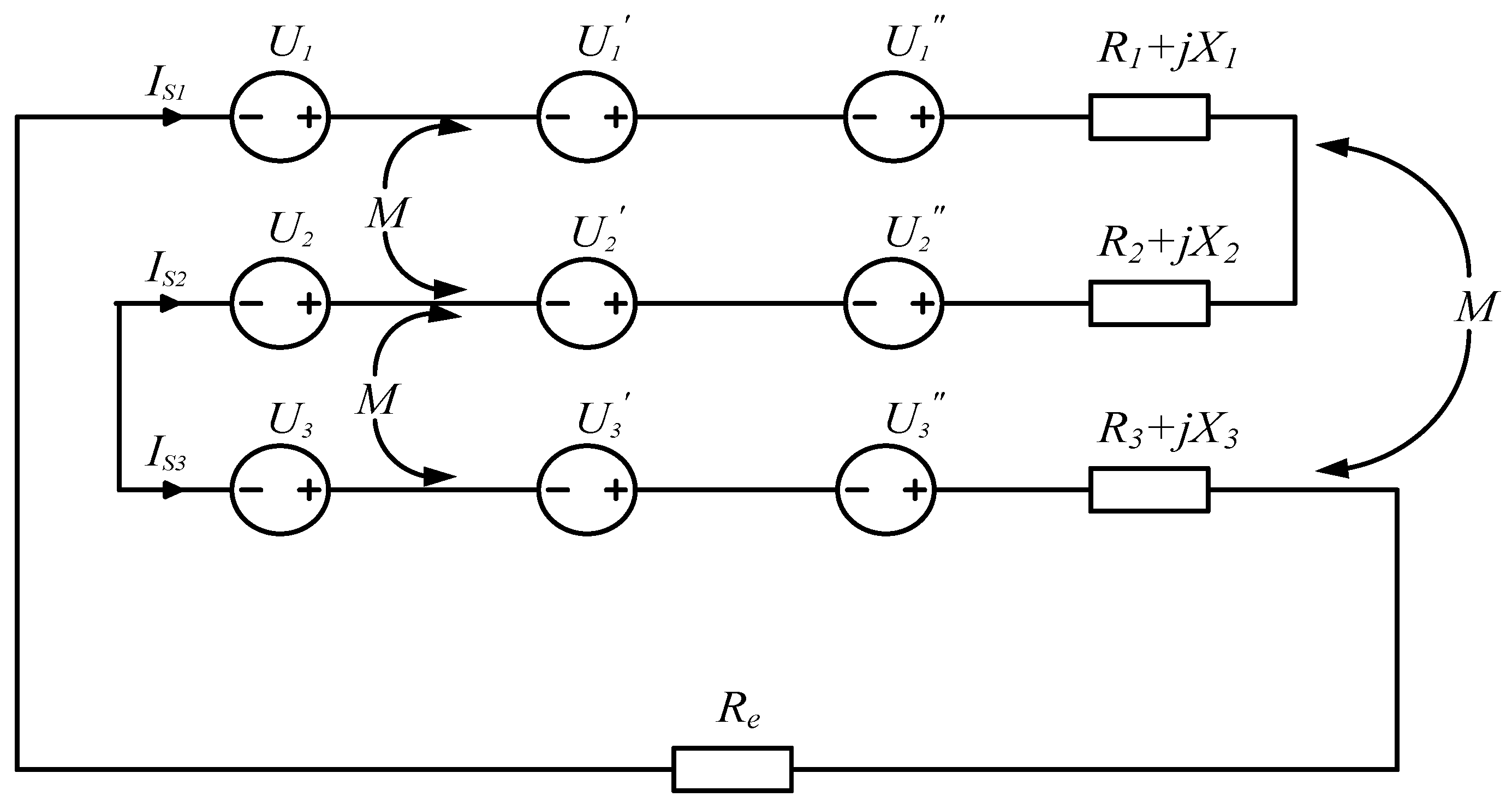
In scheme 1, the induced voltage in the sheath can be divided into two components, i.e., the component induced by the cable core current, and the component induced by the metal sheath current. The equivalent circuit for a single-loop sheath in double parallel cables is shown in
Figure 10.
Theoretically, if the length of the cross-connection sections is the same and the core currents of each phase are balanced, U1, U2 and U3 are approximately equal to 0 and the phase and magnitudes of U1′, U2′ and U3′ are equal. The circulating current is determined by the total induced voltage in the sheath circuit and the total impedance of the circuit. Reducing the induced voltage and increasing the loop impedance is an effective approach with which to suppress the sheath circulating current.
Figure 10 is the equivalent circuit of the sheath. Generally,
U1″ is larger than
U1 and
U1′,
U2″ is larger than
U2 and
U2′, and
U3″ is larger than
U3 and
U3′. Thus, the induced voltage by the sheath circulating current of the other loop, such as
U1″,
U2″ and
U3″, can generate a large circulating current. The lower the coupling degree of each cable sheath is, the lower the values of
U1″,
U2″ and
U3″ will be. In order to study the principle of scheme 3 to suppress the sheath circulating current, the core current and sheath circulating current of parallel cable under triangular horizontal arrangement are listed in
Table 7.
In scheme 3, the circulating current is significantly reduced in all phase sequences, except for the symmetrical phase sequence ABC-acb, and the circulating current is reduced by up to 75% in the case of ABC-abc phase sequence. When the asymmetrical parallel cables adopt scheme 3, each loop only has one sheath circuit and the direction of Is2 is opposite to Is1 and Is3. At this time, the coupling between the sheaths of different cable loops is reduced, which makes the coupling between U1″, U2″ and U3″ lower than that in scheme 1.
From
Table 7, in scheme 1, the optimal phase sequence under triangular horizontal arrangement is ABC-acb, and
U1′ and
U1″,
U2′ and
U2″, and
U3′ and
U3″ are arranged in the opposite direction in the same loop. Since the ABC-acb phase sequence is spatially symmetrical, their phase and magnitude of circulating currents are equal in two sheath loops, respectively, which makes them mutually suppressed.
As shown in
Figure 11, each sheath circuit consists of the sheaths of all parallel cables in scheme 3. The impedance matrix of parallel cable in scheme 3 is derived from the transfomation impedance matrix in scheme 1. When the parallel cable adopts scheme 3, its impedance matrix is symmetrical even though the arrangement of parallel cables is asymmetric. The coupling between the sheaths will suppress the circulating current.
To verify the proposed method, simulations are performed for each phase sequence under the triangular horizontal arrangement. The circulating currents of the metal sheaths are shown in
Table 8.
The circulating current of sheath in scheme 2 is remarkably smaller than that in scheme 1, and the phase and magnitude of open-circuit voltage in three circuits are equal, respectively, whether the core currents of each sub-cable are equal or unequal. The circulating currents of parallel cables in schemes 1 and 2 under symmetrical arrangement are equal. When the sheath circulating current is significantly reduced, the shielding effect of the sheath on the core is weakened and the core current distribution under this situation will be very close to that under one-end grounding situation. Hence, if the non-uniformity coefficient ε under one-end grounding situation is lower than 1.2, scheme 2 can be applied to parallel cable.


