

Review of Modern Control Technologies for Voltage Regulation in DC/DC Converters of DC Microgrids


1
Institute for Automation of Complex Power Systems, RWTH Aachen University, 52074 Aachen, Germany
2
Fraunhofer Institute for Applied Information Technology FIT, 53757 Sankt Augustin, Germany
*
Authors to whom correspondence should be addressed.
†
Current address: E.ON. Energy Research Center, RWTH Aachen University, Mathieustr. 10, 52074 Aachen, Germany.
Energies 2023, 16(12), 4563; https://0-doi-org.brum.beds.ac.uk/10.3390/en16124563
Submission received: 31 March 2023
/
Revised: 28 April 2023
/
Accepted: 30 April 2023
/
Published: 7 June 2023
(This article belongs to the Special Issue Control and Stability of Grid-Connected Power Electronic Converters)
Abstract
:This paper provides an overview of modern feedback control methods for the voltage regulation in DC/DC converters of DC microgrids. Control objectives and practical restrictions are defined and used as indicators for the analysis and performance assessment of the control methods. After presenting the concept of each control method, the advantages and limitations in the converter applications are discussed. The main conclusions of this overview can be used as recommendations for the selection of the suitable control method according to the control requirements in the DC microgrid. The low robustness against disturbances is a major issue in all control methods. For the enhancement of the robustness of the feedback control methods, three approaches are reviewed. Applications of these approaches in DC/DC converters are compared with regard to the achieved disturbance rejection and the related cost of nominal performance degradation. The disturbance/uncertainty estimation and attenuation (DUEA) framework appears to be the most promising approach to compromising these opposing control objectives. This overview is presented for a general DC/DC converter, without any additional control design requirement imposed by a specific converter plant. This allows the generalisation of the conclusions of the performance assessment, which can facilitate the application of the control methods in similar systems, such as in AC/DC converters or motor drives.
1. Introduction
1.1. Background—Design of Converter Controller
The recent advancements in power electronics have stimulated the grid integration of DC power sources and loads, such as solar photovoltaics, energy storage systems, electrical vehicles, and motor drive systems. DC microgrids have gained interest as they offer to these converter-interfaced distributed energy resources (DER) more efficient grid connection [1,2,3]. The fundamental building blocks of the DC microgrids are the DC/DC converters. The source-side DC/DC converters of the DC microgrid are responsible for the regulation of the DC grid voltage, to ensure stable and reliable operation of the microgrid. Therefore, the main control goal in these DC/DC converters is the regulation of their output voltage, performed by the voltage control loop.
The voltage controller of the DC/DC converter is designed according to the nominal model of the converter. This is an approximate model of the real converter plant: it is simplified and local, i.e., isolated from other components of the DC system. Figure 1 illustrates the nominal model of a DC/DC buck converter, where C is the filter capacitor, L is the filter inductor and is the parasitic resistance of the inductor. The parameters of the input voltage and load resistance R in the nominal converter model represent the source at the input port and the DC system at the output port of the real converter plant, respectively. For the design of the voltage control structure, the measurement of the capacitor voltage state (output voltage here) is used. The measurement of the inductor current state might also be used, according to the selected control method. A similar nominal model can be derived for any type of DC/DC converter. The nominal converter model compromises high fidelity, for the design of a satisfactory control for the real plant, and low model complexity, for the ease of the design and implementation of the controller. The available information for the real converter plant and the resources cost for the modelling process are also considered in the derivation of the nominal converter model [4,5].
The discrepancies between the real converter plant and its nominal model used for the control design cause disturbances when the controller is implemented in the real converter. These disturbances perturb the output voltage, degrading the performance of the controller. Considering their origin in the nominal converter model, the disturbances are categorised as internal or external. The former are caused by converter model uncertainties, e.g., varied input voltage and load resistance parameters due to changes in the operating point, unknown filter parameters, unmodelled high-frequency dynamics, and nonlinearities. The latter are caused by external forces, e.g., measurement noise and interaction dynamics with other components in the DC system.
From the viewpoint of system theory and control theory, the nominal converter model is a system that belongs to a certain class (linear/nonlinear, time-invariant/time-varying, minimum phase (MP)/nonminimum phase (NMP), etc.), according to which the suitable control method is selected. The performance of the converter controller should meet the following control objectives [4,6,7,8,9]:
- Stabilisation: the controller should be able to bring the converter to a steady state after changes in the operating point, offering large-signal stability (regulatory control problem).
- Transient response: the stabilisation should be achieved with certain dynamic performance, indicated by desired under-/overshoot, rise time, settling time, or other predefined metrics.
- Reference tracking: the controller should regulate the output voltage of the converter to the specified set-point fast and tightly, with zero steady-state error (servo control problem).
- Disturbance rejection: the controller should reject the disturbances that appear during the operation of the real converter, stabilise it and maintain transient response and reference tracking.
The first three requirements refer to the operation of the controller in the nominal converter model, and thus are mentioned as nominal stability and performance [10,11]. The requirement of the disturbance rejection is related to the robustness of the designed controller. Robustness is the ability of the controller to withstand the disturbances occurring in the real converter plant, by compensating or rejecting them, and recover the nominal stability and performance. For this, information about the disturbances (estimations, known bounds, etc.) should be incorporated in the control design. The different types and size of disturbances determine the suitable control methods that can be adopted, to deal satisfactorily with them. Critical for the selection of the control method is the classification of the disturbances to matched or mismatched according to the matching condition. The former are integrated in the nominal converter model in the same channel (dynamic state equation) as the control input, such as uncertainties of the input voltage or the filter inductance; the latter appear in different channel from the control input, like uncertainties of the load or the filter capacitance. The more accurate the information about disturbances that is incorporated in the control design, the more effective the disturbance rejection by the designed controller, and thus the lower its sensitivity to disturbances and the higher its robustness when implemented in the real converter plant. The controller, which achieves full recovery of the nominal stability and performance under all defined disturbances in the real converter plant, presents robust stability and performance [10,11]. Some of the aforementioned control objectives are opposing, e.g., servo vs. regulatory control or nominal performance vs. disturbance rejection, and this leads to design trade-offs, which should compromise them [12,13,14].
During the design of the converter controller, the following practical restrictions should be taken into account [4,6]:
- Limitations of control hardware: the converter controller should present low complexity to allow the easy implementation and fast computation in the hardware of the real converter, considering limitations of space, speed, accuracy, etc.
- Availability of measurements: the converter controller should rely only on measurable quantities of the real converter, such as the output voltage, the voltage across the filter capacitance, the current through the filter inductor, and the input voltage.
- limits of control input: the converter controller should not require excessive control effort to achieve the control objectives; these requirements refer to low magnitude and constant, low switching frequency of the control input, to avoid switching losses and filter design complications.
- Operating limits of real converter plant: the converter controller should achieve the control objectives while respecting the operating limits of the real plant, such as limits for the magnitude and rate of change of the output current.
When the controller, designed according to the nominal converter model, is implemented in the hardware of the real converter plant, adjustments in the design are performed to better compromise the aforementioned control objectives and practical restrictions. This includes the final tuning of the control parameters, to compensate the disturbances that cannot be taken into account during the control design, and thus improve the performance of the controller when implemented in the real converter. The tuning depends usually on experience and intuition and therefore is resource-costly. The more robust the designed controller, the less tuning is needed when it is implemented in the real converter plant. The control design problem for the DC/DC converters can be conceptualised as follows: design such controller for the nominal converter model, which achieves the control objectives when implemented in the real converter plant, while respecting the practical restrictions and requiring the minimum parameter tuning or other adjustments.
1.2. Motivation
The proportional-integral-derivative (PID) controller is the most common feedback control method applied in converters, due to its simple structure, easy implementation, and clear functionality, depending only on the tuning of the control parameters [7,15]. The wide application of the PID control has stimulated the development of various tuning techniques, such as analytical and frequency-response methods, as well as heuristic, optimisation, and adaptive methods [7]. The most common are the frequency-response methods, such as the Ziegler–Nichols method, which provide simple formulae to determine the PID control parameters [15,16,17]. However, these rely on a linear model of the converter, neglecting the full dynamics and nonlinearities of the real converter plant [18]. Moreover, these conventional tuning methods cannot deal with the right-half-plane (RHP) zero of the converters of the NMP system class, such as the DC/DC converters in the boost stage when the output voltage is regulated [9,19]. Hence, they provide poor control performance in the real converter plant, with an oscillatory response to disturbances, presenting high overshoot and large settling time [16,17,19]. In addition, opposing control objectives and design trade-offs are difficult to compromise through the analytical and frequency-response methods. Therefore, the tuning process becomes more subjective, leading to poorly tuned PID controllers, which in turn present poor performance requiring excessive control effort. To improve the performance of the analytical and frequency-response tuning methods, automatic tuning methods are proposed, based on learning techniques [20], fuzzy control [21], frequency-domain model identification [22], optimisation [16,23], and eigenvalues parametric sensitivities [24]. However, these tuning methods are computationally complex and have not yet managed to replace the simple Ziegler–Nichols tuning method in the real-world practice of converter controllers, resulting in the poor control performance noted above [7,16]. To overcome the limitations of the conventional tuning methods, while keeping the tuning process simple, direct synthesis-based design of the PID controllers has been recently applied in converter control [8,19,25]. This manages to deal with the converters of the NMP system class despite the bandwidth limitations, achieving better transient response and external disturbance rejection than the conventionally-tuned PID controllers. However, this PID design approach requires a known disturbance-output transfer function, and, thus, a known external disturbance model. Moreover, it requires a known model of the real converter plant, not being able to cope with model uncertainties. These limit its applicability in real-world practice. The continuing advances in digital signal processing enable the application of model-based control methods in the field of DC/DC converters. These modern control methods exhibit better performance and robustness against disturbances than the error-based PID controller. Refs. [4,26] present the mathematical formulation of such feedback control methods when applied for voltage control in DC/DC converters. Ref. [27] provides an overview of modern control methods in bidirectional DC/DC converters for the stabilisation of constant power loads (CPL) and accommodation of pulsed power loads (PPL). In these specific applications, the component of the specific DC load in the DC system is incorporated in the nominal converter model as a model parameter. This affects the formulation of the control methods in the DC/DC converters, since the controller is designed according to the included specific load model and the specific type of disturbance that this can present. A comprehensive review and comparison of modern control methods applied in dual-active-bridge (DAB) DC/DC converters is provided in [28]. However, the application of the control methods is tailored to this specific converter type, which presents certain control objectives. In both aforementioned works, the lack of generality of the used converter plant for the discussion of the control methods prevents the generalisation of the conclusions about their applicability, features, and performance in DC/DC converters. Ref. [29] reviews modern control methods applied in bidirectional DC/DC converters for the bidirectional power flow control in the specific applications of batteries and electric vehicles. Although an insight into the performance of certain control methods is provided in that work, the control goal and the applications are different from these in this overview, with different control objectives and practical restrictions. Hence, the formulation and the implementation of the control methods cannot be adopted directly. An overview of small-signal and large-signal approaches for the design and tuning of feedback and feedforward voltage and current control loops in DC/DC converters is presented in [30]. That work provides a better understanding for the different control loops in DC/DC converters and the different strategies in which these can be designed. However, the application of specific control methods is not deeply presented.
1.3. Contribution
This paper aims at contributing to the field of control design in DC/DC converters by providing an overview of modern control methods for the voltage regulation. Various methods are comprehensively reviewed, by analysing their advantages and limitations. For the assessment of the performance of the control methods, the aforementioned control objectives and practical restrictions are used as indicators. Trends of recent research on converter applications to overcome the limitations of the control methods are also discussed. Special focus is placed on the low robustness of the feedback control methods, which deteriorates its performance. The common approaches for the robustness enhancement are classified and their performance are analysed in applications of DC/DC converters. Comparisons of the alternative control solutions are made according to their features, to support the selection of the suitable control method for different application requirements. More precisely, the contributions of this work are the following:
- The wide overview of various control methods for the voltage regulation in DC/DC converters of DC microgrids; the control methods are discussed on the basis of a general plant of DC/DC converters, without imposing particular control objectives stemming from certain converter types or particular control formulation due to certain converter modelling, opposition to [27,28];
- The comprehensive review and comparison of specific control methods applied for the voltage regulation in DC/DC converters, by providing deep analysis of their advantages, limitations, similarities, and differences, opposite to other works, where only the fundamental design strategies for the control loops of the converter are presented, such as in [30];
- The detailed review of approaches and structures for the enhancement of the robustness of the feedback controllers, which is missing from the literature of DC/DC converters.
Table 1 summarises the aspects addressed in the aforementioned review papers and the differences from the aspects addressed in this paper.
1.4. Organisation of the Review
This paper is organised as follows: in Section 2 the modern feedback control methods are reviewed, by providing their theoretical concepts and the performance features of their applications in DC/DC converters. Section 3 discusses the issue of the robustness of feedback controllers, by introducing the three main approaches for robustness enhancement, and presenting their applications in DC/DC converters. Section 4 summarises the open research questions in the field of converter control and mentions the research directions that are needed to foster the adoption and application of the reviewed control methods in the DC/DC converters. Section 5 concludes the review by discussing its future usage.
2. Modern Feedback Control Methods for Voltage Regulation in DC/DC Converters
In this section, various feedback control methods are reviewed. For each method, the concept and basic theoretical principles are provided. The performance of each control method in its application in DC/DC converters is assessed according to the indicators defined in the previous section. The advantages and limitations of each method are analysed, and recent research solutions for overcoming the latter are mentioned.
2.1. Energy-Based Control
Energy-based control methods have been applied in DC/DC converters, taking advantage of the idea that a converter manages to reach its steady state by controlling the way in with which it dissipates energy. An energy-based controller shapes the variations of the energy of the converter to achieve the desired transient response and stabilisation [31]. There are two energy-based control methods, namely, the stabilising control, which is designed according to Lyapunov control methods, and the passivity-based control, relying on the structural properties of passivity and dissipativity of a system [4,26].
The stabilising control makes use of the concept of the energy in the increment, which shows the distance of the current operating point of the converter from the equilibrium point that corresponds to its minimum energy. This energy is formed as the stored energy in the filter elements of the DC/DC converter
where are the inductances of its inductors, are the capacitancies of its capacitors, and and are the deviations of inductor currents and capacitor voltages from their respective steady-state values (equilibrium point with minimum energy). The control law is derived by using the stored energy V as Lyapunov function, ensuring the decrease of the converter’s energy over time towards the minimum energy corresponding to the equilibrium point. This guarantees the global large-signal stability of the converter under disturbances away from the nominal operating point.
Fundamental applications of Lyapunov control in DC/DC converters can be found in [32], demonstrating its applicability in the NMP system of boost converters. In more recent research, ref. [33] proposes Lyapunov control for each module of a cascaded structure of DC/DC boost converters and provides guidelines for the design of the control parameter, which is critical for the convergence speed of the state trajectory to the equilibrium point. Figure 2 presents the Lyapunov controller of a boost DC/DC converter.
An important advantage of the application of Lyapunov control in converters is the more uniform transient response of the closed-loop converter system, i.e., both states of capacitor voltage and inductor current present good dynamics, related to the parameter of the Lyapunov controller [33]. This means that the Lyapunov control achieves voltage stabilisation without requiring high current injections. This cannot be achieved with other control methods, where different control parameters affect the two states. For the enhancement of the robustness against disturbances, modified Lyapunov controllers can be adopted, as in the case of inverters: adaptive laws can be included for the load disturbance estimation and can be embedded with integrators for zero steady-state errors and, thus, excellent reference tracking [34]. The complexity and computational burden of the Lyapunov controller is kept low and therefore the implementation is straightforward, since there are only algebraic computations involved in the generation of the control input [33]. Another advantage is that, at an event which causes saturation of the control input of the converter, the Lyapunov energy function is strictly decreasing and the system leaves the saturated region, as shown analytically in [4]. A drawback of the Lyapunov control is the lack of systematic design method, as the design depends on the choice of the Lyapunov energy function and the accurate reference values [33].
The passivity-based control (PBC) aims at rendering the converter passive and thus stabilising it, by shaping its stored energy [4,35,36,37]. The main advantage of passivity-based control is that the achieved passivity of the converter is perceived even after its arbitrary connection with other passive components in the DC system, ensuring, theoretically, a satisfactory performance and stability under any external disturbance of different interactions with other components [38]. A disadvantage of passivity-based control methods is the strong dependence of the control law on the converter model, which negatively affects the robustness of the controller against converter model uncertainties [4].
There are two main approaches of PBC design. In the first approach, the converter is modelled as an Euler–Lagrange (EL) dynamical system that exchanges energy with its environment: the input energy G(u, E) from exogenous electrical sources E, with u being the input vector, is equal to the stored energy in the converter circuit, the internal energy F(u)x of the converter, and the energy K(u)x dissipated to the environment, as illustrated in Figure 3 [4]. The speed with which the converter dissipates energy determines the speed of its convergence to stable operating points, and it can be controlled through damping injection means [4,26].
For DC/DC converters of the MP class, the control input is derived in a direct way and the passivity-based controller gives a globally stable closed-loop system. [39] applies the PBC in the buck DC/DC converters of a DC microgrid, by integrating virtual resistances in the electrical circuit of the converter for damping injection and using them in the PBC law, to shape the energy of the converter and thus stabilise it. In the same approach, Figure 4 presents the integration of the damping virtual resistances and in the electrical circuit of the nominal buck converter of Figure 1. Figure 4 also illustrates how the virtual resistances are used in the PBC, to determine the inductor current , corresponded to the voltage set-point , and the control input d.
However, for the converters of the NMP system class, this approach does not provide a globally stable closed-loop system [4,26]. An additional control structure is required to ensure stability, or indirect control approach is necessary, where the controlled output is redefined as expression of the inductor current [4,26]. To apply indirect voltage control in the boost DC/DC converter, Ref. [40] modifies the PBC structure of Figure 4, to include an auxiliary control loop to regulate the states towards the equilibrium point. The desired inductor current is computed according to the voltage set-point and is used in the auxiliary loop to find a bounded auxiliary state that converges to the ; this is then used to produce the control input d. However, this auxiliary control loop for the dynamic generation of the desired output includes gains and unknown converter parameters, relying on trial-and-error tuning and thus resulting in steady-state errors [41]. For achieving direct voltage control in converters of the NMP system class, Ref. [42] proposed the use of parallel-damping PBC, where virtual parallel conductances are “injected” (introduced) to the circuit to damp the capacitor voltage, opposite to the most traditional approach of the series-damping PBC, where virtual series resistances are “injected” to damp the inductor currents. This enables the regulation of the NMP system by measuring the NMP output only (output voltage of the converter), without the need for measuring the MP output of the current as in the case of series damping. In addition, the parallel damping in the PBC offers higher robustness against converter model uncertainties than the series damping, since the former preserves the passivity of the closed-loop system under changes of the operating conditions [42]. For the enhancement of the robustness of the PBC against disturbances, a more popular approach in recent research is the integration of an observer, which estimates in real time the disturbances, and provide this information to the PBC for the derivation of the suitable control law that deals with them. For example, Ref. [43] adopts this control approach in a buck DC/DC converter supplying a CPL. The power of the CPL is parameter of the nominal buck converter model at that work and thus is included in the control design. The applied nonlinear power observer estimates the changing power of the CPL, and this estimation is used to adjust the PBC law in real time. In this way, the PBC deals with changes in the power demand of the CPL and consequently in the operating point of the buck converter, becoming thus robust against converter model uncertainties. For enhancing the robustness of the PBC of a buck DC/DC converter against changing parameters of load and input voltage, Ref. [44] applies a non-linear disturbance observer. This estimates the disturbances appeared in the dynamic equations of the converter as deviations of the states. The estimated disturbances are added in the PBC law of the closed-loop system through feedforward channels, to cancel the steady-state error of the output voltage due to the changing operating point. Moving further, Ref. [40] applies the same disturbance observer-based PBC in a boost DC/DC converter. In this case, the PBC law with the feedforwarded estimated disturbance cancels also the steady-state error of the output voltage due to the application of the indirect control in the boost converter, indicated above. For the same purpose of robustness enhancement, more advanced PBC models follow model-free approaches. Ref. [38] proposed a data-driven, and thus model-free, approach for the synthesis of the PBC of DC/DC converters purely from measurement data. Therefore, the converter model uncertainties are eliminated in real time and the robustness is enhanced, without any requirement for high-fidelity converter model. In another approach, Ref. [45] introduced a voltage derivative observer in the PBC model of a boost converter, which results in a load-free approach and thus mitigated model uncertainties. Apart from the enhanced robustness, this model-independent PBC design approach lowers the implementation complexity. In addition, this work proposes adaptive damping injection in the PBC voltage controller for a time-varying convergence speed, which enlarges the closed-loop stability margin.
The second PBC approach considers port-controlled Hamiltonian (PCH) models, which encompass a very large class of nonlinear plants, containing the class of EL models [36,37]. The PCH model of a nonlinear converter plant is a network (interconnection) of the filter elements of the converter and is formulated as [36]:
where x are the energy variables, and u, y are the input and output port power variables, respectively, which are conjugated variables, i.e., their duality product defines the power flow exchanged between the converter plant and its environment. The skew-symmetric matrix is known as the interconnection matrix, capturing the interconnection structure of the filter elements of the converter, the matrix is called the dissipation (damping) matrix of the converter, the smooth function represents the total stored energy of the converter and the matrix is the input matrix of the converter system [36]. The PCH model is used in the so-called interconnection and damping assignment (IDA) PBC method, which has physical interpretations and thus is defined considering the real converter plant [37]. Ref. [36] presents the IDA-PBC design procedure, as well as the theoretical proof that this method generates all asymptotically stabilising controllers for the PCH models.
In opposition to the main PBC approach based on the EL converter model, the main advantage of the IDA-PBC approach is that there is no need for indirect voltage control in the case of converters of the NMP class. The IDA-PBC method allows for direct voltage control with one-loop control structure, enhancing the transient response and stability of the controller. Figure 5 presents the IDA-PBC structure of a boost DC/DC converter proposed in [46]. In this control structure, k is a time-varying coefficient determined as , where , is the desired equilibrium point and , are the elements of the damping matrix . This coefficient is related to the parameter K (), which is introduced in the interconnection matrix to establish adaptively the interconnection structure of the filter elements of the converter. Through k the control law is generated according to this adaptation of interconnections. This adaptive interconnection matrix, as well as adaptive damping functions [37,47], can adjust the convergence speed and add damping in the system, enhancing thus the stability margins.
For the enhancement of the robustness, the integration of observers has been proposed to estimate the disturbance in the real converter plant; this can include also state estimation to reduce the sensors’ number. For example, Ref. [48] applies the immersion and invariance (I&I) technique to estimate the power parameter of the CPL included in the nominal model of a buck/boost DC/DC converter. In this way, the unknown parameter of the nominal converter model becomes available online and used in the design of the IDA-PBC law. A non-linear state and disturbance observer is integrated in the IDA-PBC structure of a boost DC/DC converter in [49]: the observer estimates the total disturbance, i.e., internal and external disturbances, and this estimation is included in the derivation of the state feedback IDA-PBC law. In this way, the controller becomes robust against disturbances. Moreover, for the decrease of steady-state errors due to low robustness against converter model uncertainties, the IDA-PBC models are extended with integral actions [37,50]. The stumbling block to make the IDA-PBC a viable control design method with low complexity and easy implementation is the difficulty to solve the corresponding partial differential equations. To facilitate this, Refs. [37,47] proposed approaches that include algebraic equations or parameterisation of the IDA matrices. Ref. [37] discussed the remaining open research questions that will make the IDA-PBC method a more attractive control solution for DC/DC converters: (1) the theoretical establishment of the reference tracking ability of the method, which is a requirement for DC/DC converters receiving new voltage set-points for the operation of the DC system; (2) the development of techniques to further facilitate the equations solution for the lower computational burden and thus easier implementation in the hardware of the converter; and (3) the reformulation of the stabilisation problem in terms of power instead of energy to enhance the transient response of the converter controller.
2.2. Feedback Linearisation
Feedback linearisation is one of the most analysed feedback control methods for non-linear converter models [4,26]. The input–output feedback linearisation cancels the intrinsic nonlinearities of the nominal converter model, transforming the initial nonlinear system of the converter to a linear subsystem of lower-order. In fact, this linear subsystem presents an integrator input–output behaviour, which then can be easily controlled through a linear feedback controller [4]. The application of the concept for the voltage regulation in a DC/DC converter is illustrated in the generic control structure of feedback linearisation in Figure 6. The feedback linearisation offers large-signal stability and fast transient response [51,52]. In addition, the linear input/output behaviour facilitates the accuracy of the reference tracking [51].
The major challenge of the input-output feedback linearisation is that the dynamics of the remaining subsystem, i.e., zero or internal dynamics that do not affect the output behaviour, must be stable, to ensure a stable performance of the converter. This is not valid for converters of the NMP system class [4,26]. In this case, a zero-dynamics stabilisation method should be included. This can allow for a faster controller, as the stable zero-dynamics means that the system of the converter is not band-limited. However, the introduction of the stabilisation method makes the control structure more complex [4,26]. A more common solution is the indirect control approach, as mentioned also for the EL-based PBC method [4,26]. This means that the transient response of the output voltage follows the open-loop dynamics, and thus presents higher overshoot/undershoot and larger settling time, as well as higher sensitivity to converter model uncertainties [51].
Another approach to allow the application of input–output feedback linearisation in converters of the NMP system class is to redefine the output such that the converter becomes an MP system [41,51]. Usually, a linear combination of the inductor current, input current, output voltage, or output current is considered as the redefined output of the converter. This necessitates the dynamic generation or approximation of the desired value (reference) of certain quantities (e.g., input current), which includes approximation errors or dependency on the converter model, leading to significant steady-state errors in the output voltage. Moreover, these linear combinations include trial-and-error tuning of gains for compromising the opposing objectives of stability and reference tracking, such as in [41]. In addition, the converter is prone to cross the MP-NMP boundaries during transients and exhibits the same poor dynamic performance of the indirect voltage control method [41,51]. Ref. [51] redefined the output variable of a boost converter, by sampling the output voltage during the OFF-time of the switch. This output redefinition facilitates the output voltage control. The new output redefinition method decreases the steady-state error and prevents crossing of the MP-NMP boundaries, thus providing, providing thus good dynamic performance. However, the zero dynamics become stable locally around the operating point and the feedback linearisation is also applied locally; the large-signal stability should be further analysed. In [53,54] feedback linearisation was applied in buck/boost and Cuk converters, respectively, following the redefinition of the output as a function of the states. By adjusting the coefficients of the output function, the stability of the zero dynamics is achieved and the original NMP system becomes an MP system. Opposite to the classical feedback linearisation with output redefinition, this approach does not require full feedback linearisation of the output function, which is not possible for higher-order systems such as the Cuk converter, and avoids higher-order differential terms in the final control law, making the implementation of the controller easier. In conclusion, the selection of the redefined output function is very critical for the application of feedback linearisation, to ensure good transient response, reference tracking, robustness against converter model uncertainties, and easy implementation of the final controller in the converter hardware.
An alternative approach for dealing with the converters of the NMP system class is the input-state feedback linearisation [51]. The main drawback of this approach is that it is not suitable for output tracking control (servo control problem) unless the converter system is flat, i.e., there is an expression of the desired output trajectory in terms of the states [26,51]. The flat output is usually the incremental stored energy of the DC/DC converter as function of the states of the inductor current and capacitor voltage [26].
The general drawback of the feedback linearisation method is the low robustness against converter model uncertainties. Composite control structures that include a feedback linearisation controller together with a disturbance observer have been proposed, where the observer estimates the disturbance due to model uncertainties and the control input cancels this, while achieving nominal performance recovery [4]. For example, in [55], a disturbance observer is employed, to estimate the internal and external disturbances in a boost converter. The estimated disturbance is introduced in the formulation of the feedback linearisation control law, to cancel its effect. In this way, the composite control structure achieves more accurate reference tracking under disturbances and asymptotic stabilisation thanks to the integral action of the disturbance observer.
2.3. Backstepping Control
Backstepping control, or, more precisely, integrator backstepping control, is a Lyapunov-based method to recursively design the control law for the converter. Starting from the equation of the state that is separated from the control input by the largest number of integrators, the process steps “backwards” to the other states, designing intermediate “virtual controls” for each dynamic, until the final control law for the control input is designed [56,57,58,59]. The overall control design for the system of the DC/DC converter is thus split into steps of smaller design problems for low-order cascade subsystems [60]. As an example, the design process for the backstepping control is presented here for a second-order system, which is a common model for a DC/DC converter. A coordinate transformation is applied and the converter system is converted to the canonical form:
where and are the two states and is the control input at the new set of coordinates. The goal is to make the new states , gradually track the reference values , of the new coordinates set. The state error in the new set of coordinates is defined as:
The is the virtual control law for stabilising , obtained as by considering the Lyapunov function at the first step of the backstepping control. At the second step, the Lyapunov function is considered and the virtual control law is designed as . The final control input d of the converter is derived according to the initial coordinate transformation. For converters of the NMP system class, the coordinate transformation is used for full feedback linearisation, by defining the new state as the total stored energy, to avoid the indirect voltage control through current regulation, which leads to slow response and overshoot [61,62]. The generic structure of the backstepping control applied in a boost DC/DC converter, including the coordinate transformation, is presented in Figure 7. Refs. [61,62] are two examples of application of this control structure in boost converters of DER-dominated and aircraft DC microgrids, respectively. The Lyapunov-based design of the backstepping control offers provable global asymptotic stability [57,58].
In the new set of coordinates, the backstepping control forces the nonlinear system of the converter to behave like a linear one, similarly to the feedback linearisation method. However, opposite to the feedback linearisation, which cancels all nonlinearities, the backstepping control retains in the closed-loop system the nonlinearities that act in favor, of the transient response and reference tracking [57]. This flexibility of the nonlinearities cancellation is a beneficial feature of the backstepping control in comparison to feedback linearisation, as it makes the method less restrictive design process. Hence, the backstepping control can present good performance without requiring large control effort of control laws that cannot be implemented in the converter hardware [59,63]. Fewer cancellations of nonlinearities are desirable also from the viewpoint of robustness, as exact cancellations are prone to more model errors. Therefore, the backstepping control presents higher robustness against model uncertainties than the feedback linearisation method [57]. However, it is not always easy to identify the useful non-linearities to avoid their cancellation. Application-oriented guidelines can reveal such properties of the converter plant, to enable the appropriate cancellation of the nonlinearities, which results in reduced number of recursive steps for the derivation of the control law and thus low computational burden for the controller implementation [57]. Additional analysis may be required to design more advanced Lyapunov functions and fully exploit this advantage of backstepping control.
The main disadvantage of the backstepping control is that it assumes an accurate converter model, which is not valid for real-world practice, due to, e.g., changes in the operating point of the DC system or inaccurate filter parameters. Therefore, it is sensitive to converter model uncertainties, which may lead to nonzero steady-state tracking errors. For the enhancement of the robustness against model uncertainties, as well as external disturbances, disturbance observers are integrated in the backstepping control design process. The disturbances appear in the dynamic equations of the coordinate transformation:
where represents the disturbance due to unknown load of the converter and represents other modelled uncertainties and external disturbances [64]. A more detailed discussion of the interpretation of and in the coordinate transformation of a boost converter for the application of the disturbance observer-based backstepping control can be found in [65]. At each step of the backstepping control design, the estimation of the disturbance perturbing the corresponding state is used in the virtual control law of the step in a feedforward channel that cancels this disturbance. This systematic design process for the disturbance observer-based backstepping control is applied in several works for different DC/DC converter applications, by integrating different types of observer. Ref. [66] integrates a non-linear disturbance observer in the backstepping control of a boost converter. In the same converter application, Ref. [62] applies a cubature augmented Kalman filter to estimate the states and the power load of the converter, which are then used in the backstepping control for the derivation of the reference values and virtual control laws in (4). This observer offers high accuracy and low computational burden [62]. An augmented Kalman filter is also used in [63] to estimate the states and the total disturbance at each buck converter of a DC shipboard system; this information is then included in the design of the control laws of the backstepping voltage controller of each converter, achieving stabilisation of the system and accurate reference tracking in cases of changes of the operating point. In [64], a finite-time disturbance observer is integrated in the backstepping control of each phase of an interleaved double dual (IDD) boost converter, to effectively estimate the disturbances and , which are then used at the steps of the control design. A similar disturbance observer as in [66] is applied in the backstepping control of the higher order system of a floating dual boost converter in [67], ensuring the robustness against disturbances and thus allowing the large-signal stability of that converter. Apart from the disturbance observer, as applied in the aforementioned works, Ref. [61] integrates also an input voltage estimator in the backstepping control, to ensure stability and reduce the number of sensors. In general, in all previous works, the inclusion of the estimated disturbance in the backstepping control provides disturbance rejection and thus leads to fast transient response and accurate reference tracking.
Two extensions of the backstepping control have also been widely applied for the enhancement of its robustness: adaptive backstepping achieves boundedness of the closed-loop system in the presence of parametric uncertainties in the nominal converter model, whereas robust backstepping achieves global stability under all defined disturbances in the real converter plant [56,58,59]. Adaptive backstepping is more popular, as the robust backstepping presents the disadvantages of the family of robust control, yielding to rather conservative control laws, with high gain, resulting in excitation of unmodelled dynamics, oscillatory transient response, chattering or saturation in the control signal, and high sensitivity to measurement noise [59]. Ref. [68] present detailed formulation of the adaptive backstepping control for buck/boost and boost converters and the Lyapunov functions that guarantee the stability of the adaptation mechanism for the online updating of the converter model parameters. Ref. [69] designed a digital control based on adaptive backstepping method that offers practically asymptotic stability to the closed-loop system of a buck converter. The tuning functions adaptive backstepping method is commonly used, since it avoids overparameterisation, which can result in complex, higher-order controllers [57,59]. Ref. [63] presented a detailed formulation of this method. Ref. [59] presents extensions of the adaptive backstepping control for avoiding unexpected dynamic behaviour of the parameter adaptation mechanism, improving the transient response and enhancing the robustness against control input saturation. Ref. [70] compares adaptive backstepping control with disturbance observer-based backstepping control applied in boost converter: the former ensures shorter recovery time of the output voltage when the operating point changes, whereas the latter exhibits larger robustness against changes of the voltage set-point, presenting transient response without undershoot. In recent research, more advanced methods for disturbance estimation, such as neural networks, are integrated in adaptive backstepping control structures, to estimate fast the parameters of the nominal converter model, such as the uncertain time-varying load of the converter [71].
Another approach for the enhancement of the robustness of the backstepping control is its combination with sliding mode control. In the backstepping sliding mode control (BSMC) structure, the sliding mode control rejects the parametric model uncertainties that the backstepping control cannot handle. Thanks to the sliding mode control component, the BSMC structure presents guaranteed large-signal stability, also avoiding also the unstable zero dynamics of the converters of the NMP system class. Ref. [72] applies BSMC in the system of a hybrid electric vehicle consisting of a fuel cell-interfacing boost converter and an ultra capacitor-interfacing boost/buck converter. In this application, the switching action of the sliding mode control neutralises the disturbance of the system, whereas the continuous equivalent control law of the sliding mode control is designed with the backstepping design process. To avoid the chattering phenomenon of the sliding mode control, a saturation function is applied in the switching action. The BSMC structure provides to the electric vehicle satisfactory performance in the presence of load variations. In [73], a BSMC structure is applied in a boost converter, where the sliding mode control is used for the design of the virtual control laws of the backstepping control, to deal with the disturbance appeared in the coordinate transformation as in (5). To eliminate the chattering phenomenon that is common drawback of the sliding mode control, in this work an adaptive mechanism is integrated for the online update of its gain. The resulting adaptive BSMC of the boost converter is robust against changes in the operating point thanks to the sliding mode control component, reduces the impact of chattering in the system through the adaptive mechanism, while remains simple in design and easy to implement as the backstepping control. Therefore, it exhibits the advantages of both control components, while cancelling their disadvantages. Ref. [74] follows the same approach of applying the sliding mode control to design the virtual control laws of the backstepping control of a boost converter, but it also integrates disturbance observers to estimate the disturbances, which are then used in the design of the backstepping and sliding mode control components. The disturbance observer-based BSMC is compared with the disturbance observer-based backstepping control and the simple BSMC. The former presents better transient response of the output voltage, with shorter settling time and smaller overshoot, as well as better dynamics of the inductor current, in the presence of variations in the power load or the input voltage, than the other controllers.
2.4. Sliding Mode Control
DC/DC converters are variable-structure systems, i.e., their structure switches between different configurations according to the discontinuous control input of the switches pulses [4,26]. Hence, variable-structure control of converters have gained research interest. Sliding mode control (SMC) is a well-known feedback control technique that belongs to this category [75,76]. The goal of the SMC is to bring and maintain the converter’s states on the switching surface. This is a surface in the state space on which the defined switching variable becomes zero, so that the state trajectories meet the equilibrium point and thus the output voltage becomes equal to its set-point. The motion of the state trajectories under SMC consists of two phases, as illustrated in Figure 8: the reaching phase, when the trajectory moves towards the switching surface and reaches it in finite time, and the sliding phase, during which the state trajectories slide and remain on this surface, which is called now sliding surface. In this way, the control objective of reference tracking is achieved [4,77]. The reaching phase is characterised by the control law, but the definition of the surface is also critical. Although the variable-structure control approaches design by definition discontinuous (switching) control laws, the general approach in the SMC is to design an equivalent continuous control law for retaining the sliding motion of the surface [77]. Different design approaches of the control law are reviewed in [78,79]. For fast finite-time convergence of the state trajectories to the switching surface, the terminal SMC scheme was proposed. This offers fast transient response and higher accuracy of reference tracking, but the associated singularity problem should be taken into account [80]. In the sliding phase, the sliding modes, i.e., the dynamics of the converter reaching and sliding on the sliding surface, are completely tailored only by the parameters of the surface. The sliding modes coincide with the zero dynamics of the system and should be stable. However, this is not valid for the DC/DC converters of the NMP system class. Consequently, the direct voltage control cannot be realised through the SMC method in this case of converters. Other solutions must be found, similarly to the approaches mentioned in other control methods, like indirect voltage control or suitable redefinition of the switching variable on the switching surface [4]. Ref. [81] defines the switching surface as a linear combination of the deviations of the output voltage and inductor current from their values in the equilibrium point, to apply SMC in a boost converter. For the same purpose, Ref. [82] applies exact feedback linearisation technique to convert the state space model of the boost converter to a new set of coordinates, similarly to the approach explained in Section 2.3 for the application of the backstepping control in boost converters; on this new coordinate set, the SMC control is applied for the voltage regulation of the boost converter. Figure 9 illustrates this approach for the application of the SMC in the boost converter. In this case, the non-singular terminal SMC model is applied, which provides the equivalent control input .
The main advantage of the SMC is that the generated control input is fed directly to the switches of the converter, which offers fast closed-loop response and high robustness against large-signal disturbances, opposite to the controllers designed in small-signal approaches [26,83]. However, the robustness is guaranteed only in the sliding phase, when the states remain on the switching surface. Hence, shortening or even complete elimination of the reaching phase is a desired goal in the research of SMC [77]. Moreover, the robustness does not hold for mismatched disturbances [84]. In this case, the sliding modes and thus the performance of the closed-loop system depend on the disturbances, which is not desirable, as the reference tracking error cannot converge to zero, even if the states of the system have already reached the switching surface. Large gains in the control law are needed to overcome the adverse influence of the disturbances, given that they are bounded. However, this results in large control input. For modelling or estimating the lumped disturbance and thus avoiding its effect without large control input, soft computing techniques, such as neural networks, fuzzy logic systems, evolutionary algorithms and chaos theory, can be integrated in the SMC structure. Ref. [85] provides a survey on such structures of SMC. Ref. [86] is an example application in DC/DC converters, where an interval type-2 fuzzy neural network is integrated in the SMC of a boost converter: the uncertainties of the converter model are represented through the fuzzy modelling approach and the fuzzy neural network with online adaptive rules is used to design the SMC law to deal with these internal disturbances in real time. However, the computational complexity and execution time consumption of the resulting model-free SMC structures have to be taken into consideration, as they can make more difficult the controller implementation in the converter hardware [85]. Other adaptive SMC schemes, where where the parameters of the nominal converter model are estimated by using real-time input/output data, without the employment of soft computing techniques, like in [87], have the advantage that prior testing or training process is not needed. A general approach for the robustness enhancement is the integration of a disturbance observer for the estimation of the lumped disturbance, which is then used for the design of the switching surface of the SMC [83]. Ref. [82], mentioned above for the new set of coordinates for the application of the SMC in a boost converter, employs a finite-time disturbance observer to estimate the lumped disturbances appeared in the coordinate transformation; these are used in the design of the switching surface of the SMC, to cancel their effect on the controller performance. Ref. [88] applies a finite-time disturbance observer that estimates the disturbances appearing in the coordinate transformation of a boost converter; the estimated disturbances are then used in the definition of the switching surface and the design of the SMC law for their cancellation. In a similar approach, Ref. [89] applies the delayed estimation method for the estimation of the disturbances in a buck converter, which are then included in the design of a discrete SMC for the voltage control of the converter. In these works, the enhanced robustness against disturbances offered by the disturbance estimation and cancellation allows faster transient response and more accurate reference tracking of the voltage controller of the DC/DC converter. For the particular issue of mismatched disturbances, Ref. [90] proposes an integral SMC, additionally to the integration of the disturbance observer.
The feasibility of the application of SMC for the control of DC/DC converters is challenged due to the infinitely high switching frequencies that are ideally required for retaining the sliding behaviour on the switching surface [4,83]. High switching frequencies result in excessive switching losses, inductor losses, and filter design complications, and electromagnetic interference (EMI) noise issues. In addition, the switching action interacts with parasitic dynamics of actuators and sensors, exciting unmodelled high-frequency dynamics [83,91]. Therefore, in real-world practice, the switching frequency of the control input must be restricted within a feasible range. Switching time delays should also be considered. This means that, in reality, the ideal SMC is transformed to the approximation quasi-SMC: the state trajectories do not slide on the sliding surface, but exhibit high-frequency oscillatory behaviour around the surface and thus gravitate around the equilibrium point without reaching it. This is the undesirable phenomenon of chattering. Consequently, the aforementioned control performance is deteriorated and the robustness is reduced [4,83].
The chattering phenomenon can be reduced by adding hysteresis modulation or boundary layer control, so that the issue of the finite switching frequency is compromised without sacrificing the large-signal robustness of SMC. Nevertheless, systematic design method and implementation criteria of the hysteresis-modulation-based SMC are still missing [4,83,91]. Another approach to attenuate the chattering phenomenon involves the introduction of frequency shaping in the design of the switching surface, to suppress frequency components of the sliding modes in the designated frequency band of chattering [91]. Moreover, the chattering due to interactions of the switching action with the parasitic dynamics can be neutralised by an observer, which acts as a high-frequency bypass loop [91]. A very attractive approach to deal with the chattering issue is the higher-order SMC, in which the discontinuity of the switching variable acts only on its higher-order derivatives, and thus the applied control signal remains smooth. In the higher-order SMC, the finite-time convergence to the switching surface, as well as the robustness against matched disturbances, remain valid properties as in the ideal SMC, as explained in the theory of the chattering-free SMC in [92,93,94]. The most commonly implemented higher-order SMC is the super-twisting algorithm [92]. Ref. [95] proposes a quasi-continuous second-order SMC for buck converters, demonstrating the reduction of the chattering in a real implementation. Ref. [96] compares this second-order SMC of a buck converter with adaptive and non-singular terminal first-order SMC models: the former presents faster transient response under load variations, smaller steady-state error of output voltage in changes of input voltage and faster reference tracking than the first-order SMC models, thanks to the inclusion of the second-order sliding modes in the design of the SMC. Ref. [97] presents a step-by-step design procedure for the second-order SMC of a buck converter through Lyapunov control, which offers to the closed-loop system of the converter finite-time Lyapunov stability and thus large-signal robustness against disturbances. More recent research works propose fractional-order SMC for additionally achieving the acceleration of the convergence of the state trajectories to the switching surface, and hence the improvement of the control performance [84,98]. For the higher robustness of the fractional-order SMC, Ref. [84] employed a high-order sliding-mode observer that estimates the lumped disturbance, whereas [98] introduced an adaptive fuzzy-logic system for the online adaptation of the parameters of the nominal converter model.
An additional issue of the SMC is the resulting variable switching frequency operation. Variable switching frequency complicates the design of input and output filters of the converter and deteriorates the control performance properties. Furthermore, restraining the switching noise is easier under constant switching frequency operation [83]. To keep a constant switching frequency of SMC in all operating conditions of the converter, modifications or adaptive control in the hysteresis-based SMC are proposed; another approach is the employment of PWM instead of hysteresis modulation [83,99]. The former suffer from deterioration of the transient response, more complex control structures, and the increase of the implementation cost due to additional hardware circuitries. The latter does not present these issues, but the preservation of the ideal SMC law by the PWM-based implementation is nontrivial [83].
Discrete-time implementation of the SMC can overcome the issues of the variable switching-frequency operation appearing in continuous time [83,91]. However, it should be noticed that continuous- and discrete-time SMC essentially exhibit different performance properties. The main difference is the switching frequency: in the continuous-time SMC, this tends to infinity, while in the discrete-time SMC, this is in principle, finite and it depends on the sampling frequency. This means that the switching variable is equal to zero only at the sampling instants, but its intersampling behaviour is not determined, as the control signal is frozen within a sampling period. Therefore, there is not an exact sliding motion on the sliding surface, but a quasi-sliding motion in a band around the surface. The discrete-time quasi-SMC no longer ensures robustness against disturbances, but only some degree of robustness expressed usually in terms of the magnitude of the switching variable on the switching surface [77]. Various discretisation methods of the SMC are reviewed in [76]. Event-triggered discrete-time SMC, where the event mechanisms are based on stability criteria, was proposed to reduce the size of the quasi-sliding motion band [100]. Disturbance estimation through observers can be included in the discrete-time SMC, to cancel matched or mismatched disturbances and thus enhance its robustness, as already discussed above in the case of [89]. In [101] a second-order sliding mode disturbance observer is integrated in a discretised quasi-SMC for estimation and cancellation of internal and external disturbances. This type of observer offers finite-time convergence of the disturbance estimation, which improves the transient response of the closed-loop system of the converter.
Another limitation of the SMC is the requirement for the full state measurement vector, which becomes increasingly troublesome and expensive in the high-order system of certain DC/DC converters, and it also makes the controller more vulnerable to noise as the measurements are never exact. One solution is the integration of a state observer in the structure of the SMC, to estimate the states, like in [102] where the non-linear observer of the control structure of a boost converter estimates not only the internal and external disturbances but also the states. Alternatively, output feedback approaches can be employed, where the control law requires knowledge of only the measured voltage output. However, novel switching surfaces should be designed for the output feedback SMC, to overcome the inherent limitations of direct voltage control in the converters of the NMP system class. The most attractive of such approaches is the multirate output feedback SMC, in which the measured output is sampled at a faster rate than the control input signal rate; this enables to implicitly obtaining the unmeasurable states, which are then used for the SMC design, avoiding the challenges of the output feedback SMC in the converters of the NMP system class [76,77].
2.5. Synergetic Control
Synergetic control is another variable-structure control approach. The idea of synergetic control is to define a stable, invariant, and attractive manifold or hyperplane in the state space, described by macrovariables, and design a controller to steer the state trajectories to reach and remain on this manifold [103]. The macro-variables of the manifold are defined usually as linear combinations of the error variables, i.e., the differences of inductor current and capacitor voltage from their references, like in the application of the synergetic control in boost converter in [104]. The geometric interpretation of a manifold defined as linear combination of the error variables is illustrated in Figure 10 [105]. For the synergetic control, the system of the converter is extended to include the external forces of the control input, setting actions and external disturbances as internal interactions. The synergetic control is based on these interactions of energy and information within the extended system of the converter, to induce self-organisation and lead the system to the equilibrium point [106,107]. The method of analytical design of aggregated regulators (ADAR) is applied to design control laws to steer the state trajectories to the manifold and to define recursively link equations for the desired moving dynamics along the manifold towards the equilibrium point [108]. The generic structure of the synergetic control of a buck converter is illustrated in Figure 11.
The synergetic control restricts the motion of the system of the converter on the manifold, ensuring the desired dynamic qualities according to the link equations. For this reason, the approach is also known as stabilisation and control through system restriction and manifold invariance [103,109]. In this way, the synergetic control provides asymptotic stability of the closed-loop system, the desired transient response, as well as robustness against external disturbances [108]. In addition, the construction of the link equations is based on the sequential (recursive) system decomposition, resulting in the order reduction of the system of the converter on the manifold, which lowers the controller complexity and thus simplifies its implementation in the converter hardware [103,108]. However, the capitalisation of the intrinsic properties and nonlinearities of the nominal converter model to design the synergetic control can be considered also as a weak point of the approach, as stated in several application works in DC/DC converters [110,111]. Full information about the real converter plant is required for the control design; since this is not feasible, the controller becomes less robust against converter model uncertainties, which can lead to non-zero reference tracking errors at the steady-state operation of the converter.
The suitable definition of the macrovariables of the manifold is critical for the synergetic control, since it affects the global stability, the sensitivity to converter model uncertainties, and the noise suppression [112]. Dynamic adaptation of the control parameters in the manifold is proposed in [110]: the dynamic adaptation of the slope k of the manifold in Figure 10 according to the output voltage error allows the reduction of the steady-state output voltage error, while avoiding larger overcurrents and excessive stress on the switches in the transients of the control operation. Integral terms can be added in the macrovariable function of the synergetic control of buck converters [113] or boost converters [110], to provide a control law highly insensitive to model uncertainties, by reducing the caused steady-state errors. Moreover, selective activation of the integral term can avoid its negative effect on the transient response of the closed-loop system. However, the additional integral term increases the order of the system, making the controller more complex and thus more difficult to implement [110]. Alternatively, a disturbance observer can be integrated in the control structure, to estimate the disturbance caused by the uncertain parameters of the nominal converter model, which can then be rejected to enhance the robustness of the synergetic controller, as claimed in [111]. To achieve high robustness against disturbances and thus large-signal stability, dynamic compensation of the synergetic control law according to the changes of the input voltage of a buck/boost converter has been proposed in [114]. In more recent research works, adaptive synergetic control has been also proposed for the enhancement of the robustness. In [115] a fuzzy logic system is introduced in the control structure for the online adaptation of the uncertain converter parameters, which are then considered for the design of the synergetic control law. Moreover, stochastic optimisation methods have been used for the online determination of the unknown parameters of the manifold for good transient response of the synergetic control under a wide range of operating points of the converter. Ref. [116] applies particle swarm optimisation for the design of the synergetic control of a buck converter and [117] compares this design with the one obtained by the application of a genetic algorithm: the former provides a more robust synergetic controller with faster transient response. Apart from the voltage control objective, practical restrictions, such as current limitation, can be considered by defining more complex macrovariables [110,112].
The synergetic control exhibits the same inherent beneficial characteristic as the SMC, namely, the decoupled design approach, according to which the control design problem can be broken up to two separate problems, related to the dynamics on and off the manifold, respectively [111]. For the same manifold definition, both control methods give the same dynamics on the manifold. Their difference is the manner in which the state trajectories are steered to reach the manifold. The SMC forces the trajectories to reach the switching surface within a finite period of time with variable switching frequency, whereas the synergetic control performs this exponentially and thus in a smoother manner, with constant switching frequency, as concluded in many applications in converters mentioned above [104,110,111]. In this way, the intrinsic disadvantage of the SMC, namely, the steady-state chattering at the output voltage, is avoided, preventing large converter filters [110]. In addition, opposite to the SMC, where the speed of convergence to the manifold depends only on the dynamics of the converter, in the synergetic control, the off-manifold dynamics and thus the speed of convergence to the manifold can be regulated by varying the parameters of the dynamic equations of the macrovariables [104,111]. In this way, the transient response of the closed-loop system of the converter can be designed as desired. Another advantage of the synergetic control over the SMC is the lower bandwidth requirements, although it requires comparatively more complex calculations [104,110,111]. This offers low sensitivity to high-frequency noise, and makes it more suitable for digital control implementation [111].
2.6. Optimal Control
The optimal control designs a control law that minimises a cost function, considering the test conditions and the state equations of the system of the DC/DC converter [118,119]. The cost function reflects control objectives and practical restrictions for the design of the converter controller, such as these mentioned in Section 1.1. The computational burden of the optimal control is a challenge: the corresponding control law should be found with a reasonable amount of energy in a reasonable amount of time [118]. Quadratic (2-norm) and ∞-norm cost functions present sufficient flexibility, achieving a good compromise between competing objective terms in acceptable computational effort, where other control methods become cumbersome [118].
One of the most widely applied optimal control methods is the linear quadratic regulator (LQR), designed on the basis of the linear or linearised nominal converter model [118,119,120,121]. The cost function usually includes quadratic terms of the state vector x, to minimise the average energy of the converter, and quadratic terms of the control input u, to minimise the control effort, such as in (6), where and are the corresponding weighting matrices for these two objectives. Cross-terms of the states and control input, as well as terms of other control objectives or practical restrictions, can be added in the cost function, with suitably selected weights. For example, Ref. [122] presents an LQR controller for a boost converter, where the cost function includes terms of power losses in the converter, for improving the converter’s efficiency during the transition in new operating points.
The steady-state LQR gain is usually employed in converter control, which simplifies the control design and implementation, since only constant gain amplifiers are required, avoiding the need to store time-varying gains [118]. The steady-state LQR presents good gain and phase margins, providing to the nominal converter model good transient response and guaranteeing a minimum degree of robustness against converter model uncertainties [118,119]. However, analysis of the robustness of its digital implementation is required, as the discretisation sampling brings delays in the feedback loop, resulting in phase shifts that destroy the guaranteed robustness of the continuous-time LQR. The sampling time should be kept small, approaching zero, to allow for adequate stability margins and thus robustness [118]. Moreover, the performance and robustness against large-signal disturbances occurring in the real converter plant is poor, since the control design is based on the linearised (small-signal) nominal converter model. For overcoming this drawback, various modifications of the LQR method have been proposed. The formulation of the LQR optimal control problem in terms of linear matrix inequalities (LMIs) provides rejection of converter model uncertainties at different operating conditions, with fast transient response and accurate reference tracking. Ref. [123] proposes such LMI-LQR design for the voltage control in buck and boost converters and compares its performance with the classical LQR design, to conclude on the superiority of the former with regard to good transient response under changes in the operating point. Ref. [124] compares the LMI-LQR design of the voltage controller of a boost converter with PI control design, demonstrating the better performance of the former under disturbances; this work also presents frequency-domain analysis of the disturbance rejection of the LMI-LQR design to support the time simulation results. Ref. [125] further improved the LMI-LQR controller of a boost converter by employing parameter-dependent Lyapunov functions in the control design, enhancing the robustness and improving the control performance, whilst obtaining less conservative design. For more accurate reference tracking, integral control is included in the LQR structure [118]. For improving the transient response and increasing the stability margins of the LQR method, frequency shaping techniques are also applied in the LQR design. Generally, LQR facilitates the integration of control objectives expressed in the frequency domain, since it is equivalent to the optimisation problem. Moreover, for facilitating the design of the weighting matrices of the LQR, which can be a time-consuming activity without guaranteeing the desired control performance, soft computing techniques have been applied. Ref. [126] integrates an enhanced shuffled frog-leaping optimisation algorithm to optimise the selection of the weighting matrices of an LQR controller with integral gain action applied in DC/DC X-converter. The proposed algorithm finds fast and accurately the global optimum for the design of the LQR weighting matrices, providing a converter controller with enhanced stability and transient response, while needing lower control effort. Ref. [127] uses a genetic algorithm for the design of the LQR voltage controller of a boost converter; furthermore, it applies fuzzy logic to combine different control designs, to ensure the good performance of the designed controller under different operating conditions.
A major limitation of the LQR state feedback control is the need for measuring the entire state vector, which is not practical for converter control as mentioned above. State estimation is used to overcome this issue. A stochastic state estimation (Kalman filter) is commonly integrated in the control structure to provide the needed estimated states to the LQR. The combination of the LQR and the Kalman filter forms the linear quadratic Gaussian (LQG) control method, in which the controller and the state estimator can be designed individually thanks to the separation principle [118,119]. Steady-state LQG control is usually applied, which allows the closed-loop system of the converter to be analysed as time-invariant system [118]. This is the case for the majority of LQR and LQG applications in DC/DC converters, like in [128] for a quadratic boost converter. Figure 12 illustrates the LQG voltage controller of a buck DC/DC converter, where are the matrices of the nominal state-space model of the converter, is the steady-state gain of the Kalman filter and is the steady-state gain of the LQR. An important limitation of the LQG control is the lack of guarantee of stability and robustness, opposite to the LQR [118,119,129]. Similarly to LQR, LQG presents low robustness against large-signal disturbances due to the linear control design. Hence, adaptive LQG structures have been proposed, such as reference model robust adaptive control (RMRAC), which update, online, the parameters of the nominal converter model, enhancing the robustness against converter model uncertainties [130,131]. By including a disturbance estimation in the Kalman filter of the LQG structure, Ref. [131] also achieved high robustness against external disturbances.
Loop transfer recovery (LTR) is a method commonly applied to design the LQG converter controller for recovering the stability and robustness of the LQR. This leads to a family of suboptimal controllers, and the final LQG/LTR controller is selected as a compromise between nominal performance and robustness [118,119]. However, the robustness recovery is not guaranteed for the converters of the NMP system class, and performance analysis is required at the final LQG design [118,130]. Ref. [132] applies LQG/LTR control in a multiport DC/DC converter, achieving good transient response and reference tracking, while eliminating disturbances and measurement noise. Adaptive LQG structures can be modified straightforwardly to adaptive LQG/LTR structures for converters of the MP system class. However, this is not valid for converters of the NMP system class, where high computational complexity should be taken into account for a feasible implementation [130,133].
Similarly to the LQR, the LQG method can also be modified for more accurate reference tracking and more effective disturbance rejection. The inclusion of integral control has been suggested, as in LQR, like in [134] for the case of a boost converter. For the same purpose, feedforward control is applied, but the sensitivity to converter model uncertainties should be analysed, as the resulted control structure does not hold the robustness properties [118]. As for the LQR, optimisation algorithms are applied for the design of the weighting matrices of the LQG, offering enhanced robustness against converter model uncertainties and noise. An example of such design of LQG is presented in [135] for a two-switch forward DC/DC converter.
Optimal control can be designed also by using the ∞-norm of the system of the converter as a cost function. The ∞-norm is the worst-case gain of the system, thus providing large flexibility for compromising competing control objectives, such as performance and robustness [118]. In addition, in contrast to the 2-norm, the ∞-norm allows the modelling and integration of disturbances. The optimal control method designs a feedback controller that minimises the ∞-norm of the closed-loop system of the converter [118,136,137]. The integration of control objectives, such as robustness requirements, and disturbance models through weighting functions in the control synthesis, in the so-called process of -synthesis, leads to robust stability and performance. Figure 13 presents the generic structure of optimal control applied in a DC/DC converter. Opposite to the LQR control, the optimal control offers to DC/DC converters large-signal disturbance rejection capability with guaranteed stability margins, as well as accurate reference tracking and better transient response. These advantageous features are retained even after the order reduction of the controller for easier implementation, as concluded from the application of the optimal control in buck [63], LLC resonant [138] and boost [139] converters. Adaptive mechanisms have also been integrated in control, as in the case of LQR and LQG control, for the online update of the parameters of the nominal converter model used for the controller design [140]. This enhances the robustness of the controller against converter model uncertainties.
The solution of the optimal control problem is a suboptimal controller that satisfies a bound on the ∞-norm; the optimal solution can be approximated arbitrarily closely, by decreasing the bound until a suboptimal controller no longer exists, via a search procedure in an iterative manner. The integration of a search algorithm in the converter controller makes the computational burden larger, in contrast to the optimisation problem [118,136,137]. The application of optimisation algorithms for the final selection of the optimal controller is proven to be successful in the case of DC/DC converters. Examples of such design techniques are the multi-dimentional Pareto front algorithm for the final selection of the controller of an LLC resonant DC/DC converter in [138] and the global search algorithm for the optimisation of the parameters of the weighting functions and the final design of the controller of a multi-input DC/DC converter in [141]. Refs. [142,143] apply control in buck and boost converters, respectively, by solving algebraic Riccati equations, which provide an almost optimal controller of the same order as the converter, thus keeping the implementation easy while achieving high robustness against a wide frequency range of disturbances.
Instead of the full state measurement vector, the optimal estimator can be used to estimate the converter states. By combining an optimal controller and an optimal estimator, the output feedback controller is formed [118,136,137]. The structure is similar to the LQG, but it violates the separation principle, because the estimator depends on the controller design. This results in a more complex design of the overall control structure [118,136].
2.7. Model-Predictive Control
Thanks to the increasing computational power of microprocessors and the significant advances in algorithms for solving fast and efficiently complex optimisation problems, model-predictive control (MPC) has recently become a promising design method for the converter controller [144,145]. The aim is to determine a sequence of M control inputs in a control horizon of M instants, for which the predicted output of the converter in a prediction horizon of P instants is optimal with regard to an objective function [146,147,148,149]. The principle is illustrated in Figure 14, where, in the general case, the prediction horizon is longer than the control horizon; in this case, the input is held constant after the M instants of the control horizon until the end of the prediction horizon [149]. According to the receding horizon approach, only the first control input of this sequence is actually implemented to the converter at the current sampling instant k. The control input implemented at the next sampling instant k+1 will be selected from the new sequence of control inputs determined at the instant k+1 according to updated measurements. Figure 15 presents the generic structure of two different strategies of MPC applied in a buck converter: Figure 15a illustrates the finite control set MPC method and Figure 15b illustrates the explicit MPC method. The former is the most common of the direct MPC strategies, which do not need a PWM for their application in the DC/DC converter, as the modulation is formulated and solved together with the optimisation problem. The latter belongs to the category of indirect MPC strategies, which are applied in DC/DC converters by using a PWM. It should be noted that the MPC can systematically handle nonlinearities and NMP behaviour of the nominal converter model, as in the application in a boost converter in [150].
The nature of the MPC as an optimisation problem gives the possibility to accommodate different control objectives through multiobjective functions. In addition, practical restrictions of the control input and output variables can be easily incorporated in the constraints of the optimisation problem, opposite to the LQR optimal control [144,145,151]. For this, the MPC has to be formed in such a way to deal with variables of different dynamics and nature. Modelling in different sampling times might be needed, to consider the different time responses of the various variables. The formulation of the MPC is a compromise between high flexibility of control performance and low design complexity and computational burden. Weighting factors are commonly used for the different terms of the multiobjective function, to combine variables of different nature or to determine priorities of the corresponding, probably conflicting, control objectives [144,145]. However, the tuning of these weighting factors is not trivial. Research on establishing tuning procedures is reported in [144,145], which, however, lack in generalisation. Recently artificial intelligence methods, such as neural networks and genetic algorithms, have been applied for the tuning of the weighting factors to enable their real-time adjustment and automate the tuning process. However, these require training procedures which re laborious and nonexhaustive. In many cases, the practitioners still rely on empirical procedures and trial-and-error tuning, although it is time-consuming [145]. In an attempt to establish a tuning procedure with decreased uncertainty and increased effectiveness, Ref. [151] presents basic tuning guidelines, which include classification of the terms of the objective function with the same nature to group weighting factors that can be tuned in a similar way.
The prediction horizon is a design trade-off, since large values are necessary for good transient response and stability, especially for converters of the NMP system class, but increase the computational burden exponentially. There are different approaches to deal with this issue, focusing on either the converter modelling or the computation of the optimisation problem. Finite control set MPC (FCS-MPC) schemes with prediction horizon of one instant have been proposed for keeping the computational burden low [152,153]. However, this MPC scheme acts as input–output linearisation for the converters of the NMP system class, giving unstable zero dynamics and thus unstable operation of the DC/DC converter. Ref. [154] provides a detailed analysis of this zero dynamics issue in the case of a boost converter and proposed an exact input–state linearisation of the converter to obtain a stable controller; an FCS-MPC scheme with prediction horizon one can then be used, to reduce the complexity and, thus, the computational burden. Similar approach is followed by [155], where the input–state feedback linearisation is employed in a boost converter, to enable the application of a linear MPC scheme for the voltage control. In this work it is demonstrated that the proposed controller outperforms the PID controller in transient response and reference tracking accuracy with low inductor current inrush. For low computational burden with large prediction horizons, the explicit MPC has been proposed, which solves, offline, the optimisation problem, producing a look-up table of input–output relationships (piecewise affine function—PWA) that is used for the generation of the control law during the operation of the converter. However, the produced PWA functions are usually complex and the needed online computations for their use and the generation of the final control input still remain time-consuming. Ref. [156] proposed the application of PWA-based neural network for the offline training that preserves the MPC structure, yielding a simplified PWA map used in the online computations. In a similar approach, Ref. [157] employs single-hidden-layer backpropagation neural network for the offline computation of the input-output relationships. This decreases the storage burden, of the offline control laws, but also shortens the time for the online computations. Recent research focuses on adaptive prediction horizons by integrating the computational burden in the cost terms of the objective function to deal with this design trade-off of the MPC formulation [158].
In general, the major challenge for the application of the MPC as converter controller is the design complexity, with several factors of its formulation and implementation affecting the control performance. Ref. [145] presents a detailed comparison of different expressions of the objective function and different prediction horizons of MPC schemes for converter control with regard to the achieved performance and stability. Despite the huge progress of MPC for the control of converters over the last years, there are still aspects requiring further research. Ref. [145] summarises the challenges and recent research trends in academia and industry towards the improvement of the performance of MPC, the development of advanced solvers to decrease the computational burden, and the employment of more powerful hardware platforms to facilitate the implementation of the MPC-based converter controller, without the need for compromising in performance. In addition to design and implementation aspects, the stability proof and the analysis of the MPC in the frequency domain remain as open research questions [144,145,159].
2.8. Comparison of Modern Feedback Control Methods
In the previous paragraphs, different feedback control methods for the voltage regulation in DC/DC converters were reviewed, by presenting their principles, advantages, and limitations, to assess their performance with regard to the control objectives and practical restrictions mentioned in Section 1.1. Control solutions were also presented to overcome the discussed limitations. A summary of the review is provided in Table 2, which can be used as brief recommendation for the selection of the suitable solution according to the control requirements at different applications of DC microgrids. The discussed advantages and limitations are listed in the table for each control method, for a comparison of their performance features. In addition, references of applications in DC/DC converters, as well as references of solutions to the limitations, are also provided, to offer directly examples that can be used as basis for future applications. For a better overview of the application scenarios, these references are grouped according to the type of the DC/DC converter, in which each control method is applied. The majority of application scenarios refer to source-side DC/DC converters in general DC microgrids. In few cases of the reviewed research the DC microgrid is specified, to provide an application example, without, however, imposing any additional requirement for the design of the voltage controller proposed at those works. For example, Ref. [33] refers to a battery energy storage DC system of cascaded buck converters, Refs. [46,62] present control methods for a boost converter in an electric aircraft DC microgrid, Ref. [72] works on the boost and buck/boost converters of a hybrid electric vehicle with a fuel cell and an ultracapacitor, and [63,88] propose control methods for the buck and boost converters in DC shipboard microgrid, respectively.
3. Approaches for Enhancement of Robustness of Feedback Control Methods Applied in DC/DC Converters
One major limitation that all aforementioned feedback control methods exhibit, to different extent, is the low robustness against disturbances, which deteriorates their performance. For the enhancement of the robustness, various solutions have been already presented in the previous section, such as adaptive control structures or the integration of disturbance observers. In this section, these approaches to enhance the robustness of the feedback controllers are discussed in a more systematic way. The focus now is on the technologies that offer robustness in a generic baseline feedback controller, rather than on the modification of a specific feedback control method. Three extensively utilised approaches are reviewed, by presenting their principles and common structures in their application for the voltage regulation in DC/DC converters. Tables of application references are also provided for the different approaches, for a better overview of the control structures. The section ends with a comparison between these three approaches with regard to the achieved disturbance rejection, as well as the recovery of the nominal control performance.
3.1. Adaptive Control
The main goal of the adaptive control is to adjust the behaviour of the baseline feedback controller in response to disturbances, to retain the nominal performance. To achieve this, the adaptive mechanism processes, in real time, input/output measurements of the real converter and designs/adjusts online the feedback controller or chooses the appropriate control from a set of controllers [5,160,161,162]. In this way, the adaptive control structures present inherent robustness against disturbances occurring in the real converter, while maintaining acceptable stability margins without performance degradation. For example, this is demonstrated through frequency-domain analysis in the case of a buck converter with an adaptive loop added in the conventional voltage control loop in [163]. This is opposite to the baseline feedback controllers presented above, which are fixed-gain, static control structures, causing degradation of the performance when applied in the real converter. In other words, the baseline feedback controllers heavily rely on the nominal converter model used for the design, which is an ideal model without disturbances, whereas the adaptive control structures are model-independent. Over the last decades, the field of adaptive control has experienced tremendous progress in theory. Ref. [164] traced the developments from a historical perspective by presenting the problem statements and key solutions in the field.
The generic structure of adaptive control is depicted in Figure 16. The online adaptation mechanism is designed according to the class of the adaptive control scheme. In the most widely applied class of the identifier-based adaptive control, this mechanism includes an online parameter estimator, also referred to as parameter identifier or adaptive law, and the online adjustment of the feedback controller according to the estimated control parameters. In the class of the nonidentifier-based adaptive control, the adaptive mechanism consists of stored feedback control models and an appropriate logic for selecting the right one in real time [160]. In many studies, gain scheduling is also considered as an adaptive control scheme, where the adaptation mechanism includes just a look-up table with a schedule logic [160].
The identifier-based schemes can be designed in two different approaches, according to the way the online parameter estimator is combined with the feedback control law: the indirect or explicit adaptive control and the direct or implicit adaptive control [160]. The former is more difficult in application, as the solution of the algebraic equations for the online control design is not guaranteed at each time (stabilisability problem) [160], which can be critical for the operation of the converter. The latter is suitable only for converters of the MP system class [5], and thus not applicable for the direct voltage control of DC/DC converters in the boost stage. Combined direct/indirect adaptive control schemes have been proposed, which solve the stabilisability problem of the indirect approach and relax the MP assumption of the direct approach. However, this is achieved at the cost of higher complexity of the resulted adaptive control structure [5], which makes more difficult its implementation in the converter hardware.
The most popular identifier-based schemes are the model reference adaptive control (MRAC) and the adaptive pole placement control (APPC) [5,160]. For example, an MRAC scheme is combined with an LQG controller in [131], to adjust its control parameter, for ensuring the stability and robustness against converter model uncertainties, as discussed in Section 2.6. The main limitation of the MRAC is its nonapplicability to converters of the NMP system class. On the other hand, APPC is suitable for both MP and NMP systems [160]. This scheme is usually referred to as self-regulator or autotuning scheme. Ref. [165] classifies the auto-tuning scheme as an adaptive control that is enabled and executed at discrete intervals upon event detection, regularly scheduled interval or external command. However, the term of auto-tuning is used more widely also for adaptive mechanisms that update the parameters of the feedback controller continuously, to accommodate changing operating point or external disturbances. The adaptation mechanism consists of methods, such as Ziegler–Nichols, fuzzy logic, or genetic algorithms, that evaluate, in real-time the control performance according to predefined indicators and metrics, such as damping factor and natural frequency of oscillations, to adjust the feedback controller parameters for achieving the desired behaviour determined by the control objectives [161]. Examples of the application of such APPC schemes in the DC/DC converters were discussed in the previous section, where autotuning adaptation mechanisms are introduced in the structure of baseline feedback controllers to adjust their parameters in response to real-time measurements for the enhancement of their robustness against disturbances; selectively, some are listed here again [68,98,115,140].
For the online parameter estimation, system identification (SI) techniques have been integrated in the identifier-based adaptive control structures. Ref. [166] reviewed SI techniques suitable for DC/DC converter applications. Nonparametric SI techniques, such as correlation estimation [167] and power spectrum density methods [168], have the advantage of no need for prior knowledge of the converter model. However, these techniques usually present low accuracy and speed of the parameter estimation, high sensitivity to disturbances, and high computational complexity [166]. Therefore, the feasibility of their application should be investigated at each case. Further research is required for reducing the computational complexity and the impact of disturbances on the accuracy of the parameter estimation. For example, Ref. [167] proposed an analog cross-correlation-based parameter computation, which has lower computational complexity and data storage requirements in comparison to digital correlation implementations. Parametric SI techniques have gained application interest, although these require a definition of the converter model in advance [169]. The selected converter model is always application-dependent and the complexity of the SI technique is subject to the modelling approximations [169]. Iterative and recursive estimation algorithms, such as least mean squares [170], recursive least squares [169] and Kalman filter [171], have been integrated in the adaptive control of DC/DC converters, providing simple adaptive mechanisms with higher convergence speed, higher accuracy of parameter estimation, and lower sensitivity to disturbances than the nonparametric SI techniques [166]. The main issue of these parameter estimation algorithms, especially the recursive ones, is the high computational burden due to the large number of needed mathematical operations, which may require a high-specification microprocessor for the successful implementation in the converter hardware. Hence, these techniques have not been fully exploited and adopted for the online parameter estimation in adaptive control in low-cost, low-power converter applications [169]. There are research attempts to reduce the computational complexity of these techniques, such as through the integration of dichotomous coordinate descent, which offers a fast, computationally light adaptation mechanism [169]. Ref. [170] proposed a state-space-based parametric SI technique that reduces the computational burden in comparison to transfer function-based techniques, since fewer parameters have to be estimated. Ref. [171] proposed partial update methods applied to the Kalman-filter-based SI to reduce the computational burden of the identification algorithm. Noniterative estimation methods, such as limit cycle oscillation [172] or relay schemes, present low computational burden, but suffer from low parameter estimation accuracy and cause oscillations of large amplitude in the output voltage of the converter during the identification process [166,170]. The parametric SI techniques can be easily applied in adaptive control structures such as APPC and MRAC for the online parameter estimation, and can be implemented directly in digital control designs, eliminating the errors of domain transformation [166]. However, many factors regarding the efficient implementation of the iterative estimation algorithms, like their step size, are still not discussed in literature [166]. The introduction of new-generation microprocessors allows the investigation of the capabilities of alternative SI techniques. In general, further research in the area of online parameter estimation through SI techniques is required to further reduce the computational complexity and the digital hardware usage and allow compact low-cost implementations while achieving parameter estimation of high speed and accuracy. This is imperative for the wider adoption of adaptive control in the field of DC/DC converters.
Although the adaptive control approach is adopted to enhance the robustness of the baseline feedback control, the parameter estimation of the adaptive mechanism is also sensitive to converter model uncertainties, as its design relies on the nominal converter model. This can drive the adaptive controller unstable. Modifications of the online parameter estimation have been proposed in order to enhance its robustness, such as -modification or leakage method and the use of a dead zone in the adaptation [5]. However, even these robust adaptive control methods present drawbacks, such as slow parameter adaptation leading to slow transient response of the converter controller and chattering due to dead zone of the adaptive mechanism [162]. The improvement of the performance of robust adaptive control is still an open research problem, as the proposed modifications in literature are application-dependent and rely on the ideal performance of other elements of the control structure [162].
The stabilisability problem of the indirect adaptive control and the robustness issues of the online parameter estimation do not occur in the class of the nonidentifier-based adaptive control [160]. The major advantage of this switching-based adaptive control is the rapid adaptation to sudden disturbances, which can occur during the converter operation [161]. One approach of this class is the multiple-model-adaptive control (MMAC) scheme, where a switching approach, based on a supervisory control logic, selects a feedback controller from a finite set of controllers based on the input/output measurements; the set of controllers is designed according to a set of converter models. Robust MMAC (RMMAC) schemes have been developed, where the feedback controller set is designed with robust control techniques, to account for robust stability and performance requirements [160]. Despite the good performance of the scheme, there are drawbacks related to the assumptions for the design of the models set (disturbance model, especially stochastic one, initial conditions, etc.), as well as stability limitations [160,161]. Another approach of nonidentifier-based adaptive control is the unfalsified adaptive switching control (UASC), which relies solely on input/output data to choose the feedback controller from a given set of controllers, without requiring any converter model. This provides a model-free adaptive control, thus relaxing thus the assumptions of the converter modelling included in MMAC [160,161]. The main drawback of this adaptive control scheme is the lack of guarantee that the suitable feedback controller is chosen. The multimodel UASC (MUASC) scheme, where nominal converter models can be pairwise associated with candidate feedback controllers, can reduce the switching between different controllers and the chance that destabilising controllers will be selected. This can reduce the transients in the converter performance, which cannot be guaranteed in schemes without nominal converter models [160]. More advanced adaptive control schemes mix the identifier- and nonidentifier-based approaches to take advantage of positive features of both classes. Adaptive mixing control (AMC) can mix/combine the outputs of candidate controllers, providing the advantage of smooth transition (interpolation) from one controller or combination of controllers to another [160]. This adaptive control scheme achieves accurate parameter estimation and thus stability of the closed-loop system. However, the interpolation of the control outputs, instead of discontinuous switching logic between control candidates, might render this adaptive control scheme slower to sudden disturbances than the classical switching-based adaptive control (nonidentifier-based adaptive control class).
In general, (robust) adaptive control schemes can effectively deal with large-signal disturbances, strongly enhancing the robustness of the baseline feedback controller of the structure. One main limitation is that all schemes rely, to different extent, on online learning of the real converter plant, to design or choose the suitable controller. Since the adaptive control is a highly data-driven approach, it relies on the quality of input/output data to be processed for this online learning [162]. Corrupted data by disturbances can lead to the design or selection of a feedback controller that cannot stabilise the DC/DC converter, causing large transients in the converter operation [160]. Different adaptive control schemes present different sensitivity to corrupted data and thus different probability to result in transients in the different applications. Further understanding of the difficulties associated with the process of controlling a converter, while trying to simultaneously to learn the parameters of its mathematical model from input/output data, is essential for the exploration of possible combination between adaptive mechanisms and baseline feedback control methods [160]. Furthermore, more complex approaches at the intersection of adaptive control and artificial intelligence techniques, such as machine learning, reinforcement learning and neural networks, have been proposed recently, leveraging on the suitability of those techniques in approximating the nonlinear functions of the real converter plant, without the need for “learning” a complex mathematical nominal model of the converter dynamics [161,164]. For example, in [173] a deep reinforcement learning technique is adopted for the online adjustment of the parameters of the sliding mode observer-based PI control of a buck/boost converter. The computational burden and training time and data are critical factors to be taken into account for the wide application of these promising solutions of model-free-adaptive control [162]. The advancements in microprocessors and high-speed computing technology will be proven crucial to enable further development and practical implementation of adaptive control schemes on high-bandwidth converter hardware [161]. Although active for several decades, the field of adaptive control is still a fertile research area with many immature aspects to be further investigated and clarified, such as convergence guarantees and methods for robustness analysis.
3.2. Robust Control
Robust control aims at designing feedback control laws that guarantee closed-loop stability and desired performance not only for the nominal converter model, but also for the real plant, with respect to a class of model uncertainties encountered in real life. The robust control design method incorporates the knowledge of the converter model uncertainties, as well as robustness and performance requirements, expressed as frequency-dependent weighting functions, into the feedback control design process. This provides a systematic approach to design the converter controller for high inherent robustness against model uncertainties [10,11,174,175]. The weighting functions allow to design of the controller so that the converter achieves the desired performance in a certain frequency range of its operation, whereas it presents robustness against uncertainties appearing in other frequency ranges, e.g., frequency of unmodelled dynamics [10,11,174]. This incorporation of frequency-domain uncertainty models and performance requirements in the design of robust control is related to the ∞-norm of the weighted closed-loop transfer function of the converter, as explained in Section 2.6: the ∞-norm bound of the weighted closed-loop transfer function provides a sufficient condition for robust stability and performance. Precisely, the design methodology of robust control, called -synthesis, integrates the baseline feedback controller of the optimisation problem for synthesis and the structured singular value for analysis. The robust control can deal with uncertainty models of different level of structure. The -analysis is able to handle structured and unstructured model uncertainties, opposite to the optimal control, which is not able to handle robustness bounds and performance measures associated with structured uncertainties. For the -synthesis, the control design problem is formulated into the general framework of the linear fractional transformation illustrated in Figure 17, where P represents the interconnection structure of the converter that includes the uncertainty weights, represents the uncertainties structure, K is the feedback control law, is the external disturbance and e the caused error, y is the measurement, u is the control input, and z and are outputs to and from the uncertainty block. The controller K is usually designed with an iterative technique [10,11,174,175].
Robust control manages to optimise the robustness and performance characteristics of the baseline feedback control, thus achieving thus robust stability and performance. This benefit is demonstrated in several applications in DC/DC converters. Ref. [176] provides a detailed description of uncertainties in DC/DC converters and presents the theory and procedure of the -synthesis of the robust control for a boost converter. In the same application, Ref. [177] compares the performance of the robust controller with this of the PI controller in frequency domain, demonstrating the superiority of the former in transient response and disturbance rejection. Similar comparison conclusions are also drawn in [178] for the case of a buck/boost converter. Ref. [139] demonstrates the superiority of the voltage control, assisted by a constant-gain current control loop, over the classical peak current mode controller in the case of a boost converter. The robust control exhibits better transient response under disturbances, although the order of the resulted feedback controller from the iterative technique is reduced, which is necessary to facilitate its practical implementation in the converter hardware. Full and reduced order robust control was adopted for the design of PI control for the boost converters in a hybrid power generation system in [179]. Time- and frequency-domain analyses demonstrate the higher robustness in comparison with the classical PI control.
The key point of the robust control is the uncertainty model and its validation. Further research is required to gain insight into the influence of the accuracy of the uncertainty models on the achieved robustness properties of the converter controller [10,174]. A systematic approach to expand the robust control design framework to include system identification, which can provide both nominal converter and uncertainty models, can be a major step forward for its wide application [174]. Moreover, the developed techniques for the robust control deal with the complex problem that considers complex values of uncertainties, which is a reasonable assumption only for uncertainties representing unmodelled dynamics. However, these techniques cannot deal well with real values of uncertainties, such as parametric uncertainties, resulting in conservative robust control designs. To handle the mixed problem, where the uncertainties can have both real and complex values, Refs. [10,180] suggest the use of alternative iterative techniques for the design of the controller K. Although the mixed problem is more realistic approach in the case of converters, where the model uncertainties can appear as real parametric uncertainties, while the performance specifications are modelled as fictitious complex weighting functions, the developed techniques are not widely applied. More work is necessary to provide insight in their features, advantages, and limitations in their applications in the field of DC/DC converters.
3.3. Disturbance and Uncertainty Estimation and Attenuation (DUEA)
DUEA is a family of control techniques sharing the same fundamental idea of dealing with disturbances in the real converter: in addition to the baseline feedback control action, there is a mechanism that estimates the total disturbance and rejects this directly through a feedforward cancellation action [181,182,183,184]. The total disturbance is a lumped disturbance that refers to both external and internal disturbances. Although these control techniques became known with the name DUEA, the aim is not only to attenuate/suppress the disturbance, but to cancel it directly in the sense of totality and finality, i.e., after the disturbance rejection, there is no effect of it on the operation of the converter, thus achieving the absolute invariance. In that sense, this principle of disturbance rejection is similar to the invariance principle. For this reason, the DUEA techniques are also referred to as disturbance rejection control (DRC) techniques [182]. They are also mentioned as active antidisturbance control. This is opposite to the passive antidisturbance control approach of feedback control structures without the feedforward disturbance cancellation, such as the modern control methods of Section 2 or robust and adaptive control described in Section 3.1 and Section 3.2, respectively. The passive antidisturbance control in DC/DC converters is driven only by the difference between the output voltage and its set-point, with the goal to attenuate the disturbance that tends to drive the output away from this set-point. Hence, it cannot react directly to disturbances and thus it can only compensate for them in a relatively slow manner, opposite to the DUEA approach [181,182].
The generic structure of DUEA (or DRC) is illustrated in Figure 18 and consists of the disturbance rejector and the feedback controller. The disturbance rejector includes the state and disturbance estimation and the disturbance cancellation [182].
The composite control action (control input) consists of two terms:
where is a feedback term generated by the feedback controller and is a feedforward term generated by the disturbance rejector [181,183]. As appears in (7), the control action is shared between the feedback controller and the disturbance rejector. The idea is that the rejector estimates and cancels, in real time, the total disturbance, to transform the real converter plant to the enforced plant, which is the nominal converter model. This enforced plant, which is a disturbance-free converter model, represents the dynamics to be controlled by the feedback controller [182]. The inner feedforward loop is thus designed for the control objective of disturbance rejection, and the feedback control loop is designed independently for the enforced plant, meeting the control objectives of nominal performance [181,183]. This two-degrees-of-freedom control structure allows the meeting simultaneously conflicting control objectives. The separate design of the two loops also provides design flexibility to the DUEA structure, as various disturbance estimation methods can be integrated in various baseline feedback controllers, such as these presented in Section 2.
The notions of the total disturbance, the disturbance rejector loop, and the enforced plant bring benefits for the design of the DUEA structure. Since the model uncertainties are cancelled as part of the total disturbance, there is no need for a high-fidelity model of the real converter to design the feedback controller. This means that in DUEA structures, the complexity of the control design problem, associated with nonlinear, uncertain, time-varying converter models, can be decreased [182]. Moreover, the conventional boundaries of system classes (linear or nonlinear, time-varying or time-invariant, MP or NMP, etc.), setting apart different control methods, are completely dissolved [185]. The feedback controller can be designed according to a simple nominal converter model by simply applying any modern control method presented in Section 2, without the concern of possible robustness issues discussed in Section 2, as the disturbance rejector cancels the model uncertainties. In addition, by assuming the natural couplings of the real converter as part of the total disturbance to be rejected, the DUEA provides decoupling control, forming the converter model as a simple input/output relation to be used for the feedback control design [186]. This approach is advantageous in terms of design time and cost, considering many existing decoupling control approaches, where the accurate mathematical model of the real converter plant is needed for formulating and controlling the cross-couplings [187,188]. For example, such a control approach provides effective decoupling control of power flows in a four-port multi-active bridge converter in [189], requiring information only about the system order of the converter.
In that sense, the DUEA techniques are model-independent control design approaches, needing only information about the system order of the converter, as in model-free control [182,186,190]. In practice, this means that the gains of the feedback controller are independent of the converter plant, as it is designed for the simple, disturbance-free nominal model. This allows the same feedback controller to be applied in different DC/DC converters. The limit of this general applicability is determined by the timescale of the converter that reflects its dynamics. Different converters with the same timescale can be controlled by the same controller of the DUEA control structure, without any gain tuning or other modification. Even more, the control gains can be adjusted easily between converters of different timescales [191,192,193]. Furthermore, exactly because the total disturbance is estimated and cancelled, there is no need for large value of the gain of the feedback controller for disturbance rejection, as in the concept of the high-gain control [194]. In addition, opposite to the control methods presented in Section 2 relying only on feedback loop, in the DUEA structure the feedback control does not need to include additional integrators to achieve accurate reference tracking, as the needed integral action is provided through the disturbance rejection [195].
These benefits for the DUEA design occur thanks to the disturbance rejector loop. The fast and accurate estimation of the total disturbance, including as much frequency information as possible, is critical for the good performance of the DUEA applied in DC/DC converters due to the fast dynamics in DC systems. On the other hand, the transfer of high-frequency noise from the sensors of the converter into the control signal, through the disturbance estimation, can easily cause actuator saturation and thus decrease of the control quality. Therefore, the proper design of the disturbance rejector, to compromise between speed and accuracy of the disturbance estimation and sensitivity to noise, is essential for the good performance of the DUEA when applied in DC/DC converters. Moreover, the better the disturbance estimation and cancellation in the rejector, the simpler the enforced nominal converter model can be considered for the feedback control design [182]. On the other hand, the more accurate the converter the model is considered in the design of the disturbance rejector, the lesser the computational burden and the latency of the disturbance estimation. The more accurate and fast the disturbance estimation, the more effective the disturbance rejection. This leads the performance of the feedback controller to be closer to the nominal, with fast transient response and accurate reference tracking. Considering these relations of converter modelling, disturbance estimation and rejection, and performance of the feedback controller, the quality of the DUEA control structure depends on the balance between the design of the disturbance rejector and the design of the feedback controller, according to the benefits and costs of these designs [182].
The disturbance rejection makes the DUEA techniques more anticipatory than the error-based PID control. Therefore, the DUEA techniques present significant reduction in the control effort. In PID control, this can be addressed through feedforward terms, which have to be customised for each converter and thus depend strongly on the knowledge about the converter and the disturbance [186].
Apart from the various feedback control methods that can be applied, the disturbance rejector can also take various forms. Considering the different disturbance rejectors, various DUEA techniques have been developed, such as disturbance observer-based control (DOBC), extended state observer (ESO) in active disturbance rejection control (ADRC), uncertainty and disturbance estimator (UDE)-based control, unknown input observer (UIO) in disturbance accommodation control (DAC), equivalent input disturbance (EID) estimator-based control, and generalised proportional-integral observer (GPIO)-based control [183]. Although these DUEA techniques have been developed starting from different perspectives and for different application purposes, they present strong conceptual similarities. Indeed, they can all be reduced to the basic structure of the DUEA (DRC) of Figure 18, where the disturbance estimation and cancellation are now unified in the notion of the disturbance rejector [182]. Hence, the DUEA structure acts as an umbrella platform, a framework, which encompasses all aforementioned methods. Moreover, it provides a generalised principle, according to which various control solutions can be categorised and their similarities and differences can be organised, especially in terms of the nature of the total disturbance and how this is treated for its estimation and cancellation. Through the DUEA framework, previously scattered work in the field of disturbance rejection can now be sensibly understood and reconnected in a systematic way to reveal its full potential [186].
The most common DUEA techniques are the DOBC and the ADRC; the rest of the techniques present strong similarities with these two main DUEA structures [183]. The generic structure of the DOBC is presented in Figure 19, where is the nominal model of the real converter plant , Q(s) is the filter (disturbance observer), which provides the estimate of the lumped disturbance , is the feedforward control for the disturbance cancellation, is the baseline feedback controller, is the feedback term, and is the feedforward term of the control input u, is the reference (set-point) of the output voltage y, is the measured output voltage, n is the measurement noise, and d is the external disturbance [181,183]. The filter is the most critical element of the DOBC, which is designed considering the robustness objective, as well as bandwidth limitations of the feedback controller and the converter [196,197]. The filter design can also be extended for converters of the NMP system class as described in details in [198,199,200]. Guidelines for the filter design, in terms of bandwidth constraints of the disturbance rejector, are provided in [201,202] for MP and NMP systems. To exploit the (partially) known nonlinear dynamics of the converter during the design of the DOBC structure, improving the estimation and cancellation of the disturbance, and thus the performance and robustness of the controller, nonlinear DOBC (NDOBC) techniques have been developed [181,183]. Design guidelines for full-order and reduced-order NDO in NDOBC structures were proposed in [203,204]. Ref. [205] proposed NDOBC suitable for matched and mismatched disturbances, rejecting totally the disturbance and thus providing thus higher robustness of the closed-loop system, while achieving the nominal performance. Higher-order NDO have also been proposed to exploit more structure information of higher-order disturbances, and thus facilitate their estimation and cancellation [181,183]. Ref. [206] presented a historical review of the main developments of the DOBC models.
As mentioned in Section 2, (N)DO and disturbance cancellation actions have been integrated into many baseline feedback controllers, forming (N)DOBC structures applied for voltage control in DC/DC converters. The (N)DO provide total disturbance rejection, and thus robustness enhancement, while keeping the nominal performance of the closed-loop system of the converter. In many of these works, like in [39,84], the formulation of the system with lumped disturbances in both dynamic equations of the converter or its coordinate transformation, like in (5), allows the estimation of both matched and mismatched disturbances affecting adverse the voltage regulation of the converter. This is independent from the type of the observer (e.g., finite-time, I&I, etc.). The estimated disturbances are then integrated directly in feedforward channels in the design of the feedback controller (e.g., backstepping control, SMC) to cancel their effect on the controller performance. In other cases, like in the DOBC structure of a buck converter in [207], a compensation gain is needed for the feedforward term of the mismatched disturbance in the final control law. In this work design guidelines through stability analysis are provided for this gain.
Figure 20 depicts the generic structure of the ADRC. The extended state observer (ESO) estimates the physical states of the converter together with the virtual state of the total disturbance. The estimated total disturbance is rejected by the feedforward term of the control input, passing through the disturbance cancellation block. The feedback term of the control input is generated by the feedback controller, which regulates the estimated states of the converter to the state reference trajectory provided by the tracking differentiator (TD) [183,194]. Refs. [191,192,195] provided insight into the progression of the well-known PID control to the ADRC structure. The intelligent PID (i-PID) control, where the poorly known real converter plant is estimated through numerical differentiation or algebraic parameter identification techniques and cancelled by the control law, can be considered as precursor of the more general ADRC structure [208,209,210]. The ADRC can incorporate any observer model for the estimation of the states and the total disturbance, and any baseline feedback control model, such as those in Section 2, not only the error-based PID controller.
The ESO can be designed as linear or nonlinear, with the former presenting larger convergence speed due to shorter computation but the latter presenting higher estimation accuracy. Appropriate design of a time-varying gain of the ESO can also facilitate the estimation accuracy [194]. The accepted noise sensitivity should be also considered as restriction for the ESO design [211]. Ref. [212] enhanced the linear ESO (LESO) in a DC/DC converter with a correction function, which can estimate a wider spectrum of frequencies of the total disturbance. This offers a more accurate disturbance estimation for various forms of disturbances common in the field of converters. Ref. [213] introduced the differential signal of the total disturbance as a new state in the traditional LESO of a DC/DC converter, achieving the tracking of the dynamics of the total disturbance and thus the improvement of the estimation accuracy and speed. In a more advanced ADRC model of DC/DC converter, Ref. [214] proposed a cascaded ESO based on a virtual decomposition of the total disturbance, where each ESO level is responsible for estimating different frequency range of the disturbance. In this way, the accurate estimation of the total disturbance is achieved, while the measurement noise suppression is increased, opposite to the traditional single-level high-gain ESO. This ADRC model with the cascaded ESO structure belongs to the more general category of the composite hierarchical antidisturbance control, where multiple disturbance rejector loops are used for rejecting different types of disturbances such as stochastic noise and deterministic disturbances due to unknown parameters of the converter filter. The guaranteed stability of such control structure is the main advantage, with the high complexity due to the coupling of the disturbance rejector loops being the major concern [181,183].
The TD offers a transient profile that the converter states should track. This reference profile changes gradually and thus smoother, without step jumps. This allows for a more aggressive control design, for example, with higher gains, while avoiding actuator saturation [194,195]. In addition, since the state reference trajectory is obtained through integration, it is less sensitive to noises [195]. Nonlinear TD can be applied for the generation of more accurate state reference trajectory; however, linear TD performs better in the presence of measurement noise [194]. Ref. [215] presented the design conditions of the three components of the nonlinear ADRC that guarantee stability, disturbance rejection, and reference tracking.
The original ADRC formulation, where the ESO is expressed in integral-chain form (canonical form) and the disturbance cancellation is a direct feedforward term, without any particular gain, is applicable only to converters of the MP system class and can reject only matched disturbances [216,217]. A generalised ADRC model has been proposed, where the ESO incorporates knowledge about the converter plant, and the disturbance cancellation action includes a compensation gain. The former makes the generalised ADRC applicable also to the NMP systems, whereas the latter makes it suitable for also rejecting mismatched disturbances [216,217,218]. Hence, the generalised ADRC is applicable to a wider class of converter plants and disturbance types than the original ADRC, presenting advantages in terms of disturbance rejection and performance of the closed-loop system of the converter [219].
The more general form of the nonlinear ADRC (NL-ADRC) exhibits, in most of the cases higher robustness to disturbances and better dynamic performance than the linear ADRC (L-ADRC). However, the tuning methods for NL-ADRC are limited in practical applications, because they require significant design effort and time and usually ignore physical limitations of the actuator, such as bandwidth and noise. Moreover, the theoretical analysis is a difficult task in NL-ADRC [220]. Ref. [221] used the describing function method to approximate the NL-ADRC with a linearised model, through the concept of the equivalent gain, to analyse the stability, transient response, and reference tracking in frequency domain. The L-ADRC is more transparent to practicing engineers, and thus much more applied in DC/DC converters. For example, Ref. [222] applies a L-ADRC in a boost converter and relates it to the precursor PI control, by comparing the two approaches through analysis of the achieved disturbance rejection in frequency domain. Ref. [223] integrates a reduced-order ESO to the proportional controller of a buck converter and analyses the robustness of the control structure against model uncertainties in frequency domain. However, there are still only few theoretical works for the analysis of the L-ADRC performance in the frequency domain with which practising engineers are more familiar [224,225,226]. Ref. [220] compared L-ADRC and NL-ADRC in terms of tuning ease, as well as stability and performance analysis. To integrate the merits of the L-ADRC and NL-ADRC, it also proposed a switching control scheme between L-ADRC and NL-ADRC and analysed its stability.
For promoting the application of NL-ADRC models in DC/DC converters, research activities focus on the online tuning of the parameters. For this purpose, heuristics algorithms, such as particle swarm or ant colony optimisation or fuzzy control, have been applied in the ADRC structure of DC/DC converters for the online adaptation of the control parameters, like in the case of the NL-ADRC structure of a bidirectional DC/DC converter in [227]. Further research for the online tuning of the ADRC parameters in DC/DC converters can be inspired by such applications in the similar systems of induction motors and hybrid active power filters [228,229,230]. Up until now, the NL-ADRC models applied in DC/DC converters usually refer to the abstract mathematical formulation, whose performance depends only on the tuning of the parameters. Although the ADRC approach allows and even promotes the incorporation of well-analysed existing methods for the estimation and control, as the general DUEA framework, there are only few works in which modern methods of observer or feedback controller are integrated in the ADRC structure when applied in DC/DC converters. For example, in [231] the NL-ADRC structure of a boost converter consists of a backstepping feedback controller and a generalised proportional-integral observer (GPIO). A reduced-order GPIO is also used in the ADRC model of a buck converter in [232], to enable easier practical implementation comparing to the traditional full-order ESO. In this work, the feedback controller consists of an optimal control with output voltage prediction, which enables the inclusion of performance indexes in the design of the ADRC voltage controller of the converter. Further research should be performed in this direction so that the ADRC design for the converter control can take advantage of the beneficial properties of modern control and estimation methods regarding accurate and fast estimation, high inherent robustness, excellent transient response, and accurate reference tracking. Motivation can be extracted from the successful application of such ADRC structures in the similar systems of motors [233,234].
Although the ADRC is just a particular rendition of the DUEA methods, in the literature it is considered their spearhead, and in many works the concept of the DUEA (or DRC) methods is communicated through the ADRC structure [186]. This is mostly because initially the DOBC structure was initially developed to deal with external disturbances of linear time-invariant systems, although the same structure equally applies to model uncertainties (internal disturbances) [182]. Still, the main difference between DOBC and ADRC lies on the different observers designed for the same lumped disturbance. By using the frame of the ADRC, the DOB in the DOBC can be generalised for estimating the total disturbance for nonlinear systems under certain conditions [235]. In that sense, ADRC is a more general category of DUEA methods, which can stabilise a more general class of non-linear converter systems, without setting strict mathematical constraints on the disturbances that can be estimated and rejected.
3.4. Applications of Feedback Control Methods with Enhanced Robustness for Voltage Regulation in DC/DC Converters
To provide an overview of the control structures for the robustness enhancement of the baseline feedback controllers, the applications for the voltage regulation in DC/DC converters are summarised in this section. Table 3 and Table 4 list the applications of adaptive control and DOBC, respectively, discussed in Section 2 and Section 3 according to the applied baseline feedback controller. This categorisation makes clear which feedback control methods are more suitable for the integration of adaptive mechanisms or disturbance observers. It should be mentioned that the cited applications can be found also in Table 2, as solutions for low robustness of the different feedback control methods. Therefore, the combined information from all tables can provide an overview of the scenario of each application in terms of type of converter and its control structure, including the applied baseline feedback controller and the adopted approach for the robustness enhancement.
Table 4 categorises also the DOBC applications to linear and non-linear structures. Similar categorisation is presented in Table 5 for the ADRC applications. It becomes clear that the NDOBC dominates the applications for the voltage regulation in DC/DC converters in comparison to DOBC, due to its better performance as discussed in Section 3.3. However, this is not valid in the case of the ADRC applications. Thanks to its simplicity in tuning and analysis, L-ADRC is still widely used in the real practice, although NL-ADRC outperforms, as mentioned in Section 3.3. More research is required in the area of NL-ADRC, to make clear its benefits, as discussed above.
The robust control is directly related to optimal control. Therefore, the applications of the robust control for the voltage regulation in DC/DC converters are not mentioned again here, as they can be found directly in Table 2 in the section of optimal control.
3.5. Comparison of Approaches for Enhancement of Robustness of Modern Feedback Control
The three approaches for the robustness enhancement present differences in their concept. Instead of adjusting the baseline feedback controller to the disturbances, similar to in adaptive control, in the DUEA approach the real converter plant is adjusted to what the feedback controller is designed for, i.e., the “disturbance-free” enforced plant (nominal converter model). Instead of trying to incorporate robustness objectives and disturbance models into the design of the baseline feedback controller, similar to in the robust control, the DUEA approach, tries to disregard the disturbances of the real converter plant for the feedback control design [182,186]. Therefore, in the DUEA approach, the focus of the control design for the converter is not on the accurate system identification or the high-fidelity converter and disturbance modelling, similar to in the model-based approaches of adaptive and robust control, but on the disturbance rejector design. There is a paradigm difference between the model-centric adaptive or robust control and the disturbance-centric DUEA approach [182].
With regard to the achieved disturbance rejection and the recovery of the nominal performance, the DUEA approach lies between the robust and the adaptive control, as illustrated in Figure 21, similarly to conclusions in motor drives [184]. As it can be observed, the DUEA approach might not manage to handle all disturbances appearing in the real converter plant. Therefore, it does not present so high robustness compared to the robust control, which is designed to achieve the highest possible robust stability and performance, by rejecting all defined disturbances. However, the DUEA approach presents promising inherent robustness too, thanks to the total disturbance estimation and rejection, and thus it can be regarded as a “refined” robust control approach [184]. On the other hand, it can maintain the nominal performance, as the feedback controller is designed for the disturbance-free nominal converter model. This is opposite to the robust control, where the nominal performance is sacrificed for the robustness, due to the fixed conservative design according to the worst disturbance. In practice, this means that the converters, which operate, in most of their operational time, close to their nominal operating point, will usually present degraded performance when robust control is applied. In the case of the DUEA application, this issue does not occur. In addition, the robustness of the existing adaptive control techniques against model uncertainties is low, since the adaptive mechanism is highly converter-model-dependent, as discussed in Section 3.1. On the contrary, the DUEA techniques manage to reject such disturbances as part of the total disturbance. As a result, adaptive controllers might become unstable due to unmodelled high-order dynamics of the converter, whereas the DUEA techniques maintain good performance.
4. Discussion
The reviewed papers in the previous sections prove that there is a lot of progress in the application of these modern control methods in the voltage regulation of DC/DC converters. However, there are still aspects that need further investigation with regard to the design and development of the control methods, the theoretical analysis of these models and their implementation and execution in the hardware of the converter.
On the direction of new developments, further research is needed for the combination of different approaches and techniques, to leverage on the advantages of all involved components, while cancelling their disadvantages. The development of robust adaptive control models is still an open research question, by making the adaptive mechanisms actually model-independent. The integration of artificial intelligence techniques in the control of converters is a fertile research area, which can yield solutions towards the robustification of the existing adaptive control schemes. On the other hand, adaptation of robust control is required to relax its conservative design. Research should be focused on the inclusion of adaptation mechanisms in the robust control for the online modelling of the converter with the related disturbances, to avoid worse-case gain design. In the area of DUEA, new designs should be developed, by combining different observers with different feedback controllers. This will make the DUEA models more appealing for certain applications, where certain control or estimation methods present advantages. Moreover, the comparison of different DUEA techniques and models should be widely promoted, since it can reveal similarities in methods and possibilities of exchange of components between the different models, according to the control objectives of each application.
In the area of the theoretical analysis of the modern control models, the development of new tools for the analysis in the frequency domain is required in almost all cases of the aforementioned control methods. This will provide to the practicing engineers a better understanding of their benefits and potential for the effective voltage regulation in DC/DC converters. The research in this area should focus on the derivation of guidelines for a systematic design of the converter controllers. Moreover, research effort should be put on the theoretical proof of the properties of the control models, which will enable their wider adoption in the field of converter control.
Regarding implementation and execution aspects, the complexity of the modern control methods and the resulted computational burden are challenging factors to make them feasible control solutions for DC/DC converters. The issue will become more and more critical, as the control structures will become more complex with the integration of more advanced components, e.g., artificial intelligence. Although there is huge progress in the field of microprocessors for the control execution, there are still open questions requiring further research. Apart from new developments in high-speed computing technology, advancements in software (solver algorithms) are required, to enable the solution of the control equations in lower computational burden and thus the effective execution in high-bandwidth hardware.
The research in these areas can lead to better performance of the modern contro methods and easier implementation, rendering them more promising solutions than the common industrial practice of PID control.
5. Conclusions and Future Work
This paper provides an overview of modern feedback control methods for the voltage regulation in DC/DC converters of DC microgrids. The fundamental theory of each control method is provided, by presenting its concept and properties. The advantages and limitations of the methods when applied in the DC/DC converters are discussed, with regard to the following indicators: required fidelity of the nominal converter model, the applicability to different classes of the converter system, the achieved recovery of the nominal performance in the real converter, the type of disturbances that can be rejected, the computational complexity, the control effort and ease of the implementation in the converter hardware. Recent application trends and open research questions for overcoming the limitations and improving the performance are also mentioned. A comparison of the feedback control methods is provided, which can be useful for the selection of the suitable method according to the performance requirements of the DC/DC converters in the DC microgrid. The low robustness against converter model uncertainties and external disturbances is found to be a major issue in all feedback control methods, to different extent at each. This is critical challenge for the performance of the DC/DC converter, whose operation is subject to disturbances, as the operating point changes continuously, due to variations at the load and input source, and the conditions of the DC systems alter with the increasing integration of converters and their connection/disconnection in the network. For the enhancement of the robustness, three approaches are reviewed, namely the adaptive control, the robust control and the DUEA framework, by providing their principles and common structures for their application in DC/DC converters. These approaches are also compared with regard to the achieved robustness enhancement and the relevant cost of the nominal performance degradation. The DUEA is found to be the most promising approach for converter applications, managing a good balance between nominal performance recovery in the real converter and high robustness against disturbances, through a flexible design of low complexity, opposite to most existing robust and adaptive control models.
This work reviews research on the voltage regulation in DC/DC converters. The majority of the examples presented here refer to buck, boost or buck/boost converters, as these present a simple switch configuration, which does not impose particular requirements for the control design. Hence, from the viewpoint of control, such a DC/DC converter type acts as a general plant. The control methods are discussed for their applicability and performance in this general plant of the DC/DC converter. This overview can provide recommendations for the application of the control methods in any DC/DC converter type. The deep insight in the principles of the control methods, offered in this paper, makes possible any needed adjustment in their structure, for incorporating additional control objectives or practical restrictions related to the certain DC/DC converter type of each application. Moreover, the understanding of the advantages and limitations of the reviewed control methods can facilitate the selection of the suitable solution for other control problems in DC/DC converters, like current or power control. In addition, this overview can provide useful recommendations for the control design for the voltage regulation in AC/DC converters, as the control objectives and practical restrictions are similar as in the DC/DC converters discussed here. Furthermore, this review can suggest possible control solutions for motor drives and active power filters, which are systems similar to the DC/DC converters.
Author Contributions
Conceptualization, A.K.; methodology, A.K.; formal analysis, A.K.; investigation, A.K.; resources, A.K.; writing—original draft preparation, A.K.; writing—review and editing, A.M.; supervision, A.M.; funding acquisition, A.M. All authors have read and agreed to the published version of the manuscript.
Funding
This research was funded by Bundesministerium für Forschung und Bildung, Forschungscampus Elektrische Netze der Zukunft grant number FKZ: 03SF0594.
Data Availability Statement
No new data were created or analyzed in this study. Data sharing is not applicable to this article.
Conflicts of Interest
The authors declare no conflict of interest. The funders had no role in the design of the study; in the collection, analyses, or interpretation of data; in the writing of the manuscript; or in the decision to publish the results.
References
- Dragičević, T.; Lu, X.; Vasquez, J.C.; Guerrero, J.M. DC Microgrids—Part I: A Review of Control Strategies and Stabilization Techniques. IEEE Trans. Power Electron. 2016, 31, 4876–4891. [Google Scholar] [CrossRef] [Green Version]
- Dragičević, T.; Lu, X.; Vasquez, J.C.; Guerrero, J.M. DC Microgrids—Part II: A Review of Power Architectures, Applications, and Standardization Issues. IEEE Trans. Power Electron. 2016, 31, 3528–3549. [Google Scholar] [CrossRef] [Green Version]
- Nuutinen, P.; Kaipia, T.; Peltoniemi, P.; Lana, A.; Pinomaa, A.; Mattsson, A.; Silventoinen, P.; Partanen, J.; Lohjala, J.; Matikainen, M. Research Site for Low-Voltage Direct Current Distribution in a Utility Network—Structure, Functions, and Operation. IEEE Trans. Smart Grid 2014, 5, 2574–2582. [Google Scholar] [CrossRef]
- Bacha, S.; Munteanu, I.; Bratcu, A.I. Power Electronic Converters Modeling and Control. In Advanced Textbooks in Control and Signal Processing; Springer: London, UK, 2014. [Google Scholar] [CrossRef]
- Ioannou, P.; Sun, J. Robust Adaptive Control; Dover Books on Electrical Engineering; Dover Publications: Mineola, NY, USA, 2012. [Google Scholar]
- Mariethoz, S.; Almer, S.; Baja, M.; Beccuti, A.G.; Patino, D.; Wernrud, A.; Buisson, J.; Cormerais, H.; Geyer, T.; Fujioka, H.; et al. Comparison of Hybrid Control Techniques for Buck and Boost DC-DC Converters. IEEE Trans. Control Syst. Technol. 2010, 18, 1126–1145. [Google Scholar] [CrossRef]
- Ang, K.H.; Chong, G.; Li, Y. PID control system analysis, design, and technology. IEEE Trans. Control Syst. Technol. 2005, 13, 559–576. [Google Scholar] [CrossRef] [Green Version]
- Kobaku, T.; Jeyasenthil, R.; Sahoo, S.; Dragicevic, T. Experimental Verification of Robust PID Controller under Feedforward Framework for a Nonminimum Phase DC–DC Boost Converter. IEEE J. Emerg. Sel. Top. Power Electron. 2021, 9, 3373–3383. [Google Scholar] [CrossRef]
- Kobaku, T.; Patwardhan, S.C.; Agarwal, V. Experimental Evaluation of Internal Model Control Scheme on a DC–DC Boost Converter Exhibiting Nonminimum Phase Behavior. IEEE Trans. Power Electron. 2017, 32, 8880–8891. [Google Scholar] [CrossRef]
- Zhou, K.; Doyle, J. Essentials of Robust Control; In Prentice Hall Modular Series for Eng; Prentice Hall: Hoboken, NJ, USA, 1998. [Google Scholar]
- Scherer, C. Theory of Robust Control: WB2415; TU Delft: Delft, The Netherlands, 2007. [Google Scholar]
- Garpinger, O.; Hägglund, T.; Åström, K.J. Performance and robustness trade-offs in PID control. J. Process. Control 2014, 24, 568–577. [Google Scholar] [CrossRef]
- Garpinger, O.; Hägglund, T. Software-based optimal PID design with robustness and noise sensitivity constraints. J. Process. Control 2015, 33, 90–101. [Google Scholar] [CrossRef]
- Alcántara, S.; Vilanova, R.; Pedret, C. PID control in terms of robustness/performance and servo/regulator trade-offs: A unifying approach to balanced autotuning. J. Process. Control 2013, 23, 527–542. [Google Scholar] [CrossRef]
- Åström, K.; Hägglund, T. The future of PID control. Control Eng. Pract. 2001, 9, 1163–1175. [Google Scholar] [CrossRef]
- Liu, G.; Daley, S. Optimal-tuning PID control for industrial systems. Control Eng. Pract. 2001, 9, 1185–1194. [Google Scholar] [CrossRef]
- Mikhalevich, S.S.; Baydali, S.A.; Manenti, F. Development of a tunable method for PID controllers to achieve the desired phase margin. J. Process. Control 2015, 25, 28–34. [Google Scholar] [CrossRef]
- Hwu, K.; Yau, Y. Performance Enhancement of Boost Converter Based on PID Controller Plus Linear-to-Nonlinear Translator. IEEE Trans. Power Electron. 2010, 25, 1351–1361. [Google Scholar] [CrossRef]
- Kobaku, T.; Jeyasenthil, R.; Sahoo, S.; Ramchand, R.; Dragicevic, T. Quantitative Feedback Design-Based Robust PID Control of Voltage Mode Controlled DC-DC Boost Converter. IEEE Trans. Circuits Syst.—II Express Briefs 2021, 68, 286–290. [Google Scholar] [CrossRef]
- Kansha, Y.; Jia, L.; Chiu, M.S. Self-tuning PID controllers based on the Lyapunov approach. Chem. Eng. Sci. 2008, 63, 2732–2740. [Google Scholar] [CrossRef]
- Ahn, K.; Truong, D. Online tuning fuzzy PID controller using robust extended Kalman filter. J. Process. Control 2009, 19, 1011–1023. [Google Scholar] [CrossRef]
- Wang, L. Automatic tuning of PID controllers using frequency sampling filters. IET Control Theory Appl. 2017, 11, 985–995. [Google Scholar] [CrossRef]
- Toscano, R.; Lyonnet, P. Robust PID controller tuning based on the heuristic Kalman algorithm. Automatica 2009, 45, 2099–2106. [Google Scholar] [CrossRef]
- D’Arco, S.; Suul, J.A.; Fosso, O.B. Automatic Tuning of Cascaded Controllers for Power Converters Using Eigenvalue Parametric Sensitivities. IEEE Trans. Ind. Appl. 2015, 51, 1743–1753. [Google Scholar] [CrossRef]
- Chen, D.; Seborg, D.E. PI/PID Controller Design Based on Direct Synthesis and Disturbance Rejection. Ind. Eng. Chem. Res. 2002, 41, 4807–4822. [Google Scholar] [CrossRef]
- Sira-Ramírez, H.; Silva-Ortigoza, R. Control Design Techniques in Power Electronics Devices; Power Systems; Springer: London, UK, 2006. [Google Scholar] [CrossRef]
- Xu, Q.; Vafamand, N.; Chen, L.; Dragičević, T.; Xie, L.; Blaabjerg, F. Review on Advanced Control Technologies for Bidirectional DC/DC Converters in DC Microgrids. IEEE J. Emerg. Sel. Top. Power Electron. 2021, 9, 1205–1221. [Google Scholar] [CrossRef]
- Shao, S.; Chen, L.; Shan, Z.; Gao, F.; Chen, H.; Sha, D.; Dragičević, T. Modeling and Advanced Control of Dual-Active-Bridge DC–DC Converters: A Review. IEEE Trans. Power Electron. 2022, 37, 1524–1547. [Google Scholar] [CrossRef]
- Gorji, S.A.; Sahebi, H.G.; Ektesabi, M.; Rad, A.B. Topologies and Control Schemes of Bidirectional DC–DC Power Converters: An Overview. IEEE Access 2019, 7, 117997–118019. [Google Scholar] [CrossRef]
- Kapat, S.; Krein, P.T. A Tutorial and Review Discussion of Modulation, Control and Tuning of High-Performance DC-DC Converters Based on Small-Signal and Large-Signal Approaches. IEEE Open J. Power Electron. 2020, 1, 339–371. [Google Scholar] [CrossRef]
- Cecati, C.; Dell’Aquila, A.; Liserre, M.; Monopoli, V.G. A passivity-based multilevel active rectifier with adaptive compensation for traction applications. IEEE Trans. Ind. Appl. 2003, 39, 1404–1413. [Google Scholar] [CrossRef]
- Sanders, S.; Verghese, G. Lyapunov-based control for switched power converters. IEEE Trans. Power Electron. 1992, 7, 17–24. [Google Scholar] [CrossRef] [Green Version]
- Mukherjee, N.; Strickland, D. Control of cascaded DC-DC converter-based hybrid battery energy storage systems—Part II: Lyapunov approach. IEEE Trans. Ind. Electron. 2016, 63, 3050–3059. [Google Scholar] [CrossRef] [Green Version]
- He, J.; Zhang, X.; Ma, H.; Cai, C. Lyapunov-based large-signal control of three-phase stand-alone inverters with inherent dual control loops and load disturbance adaptivity. IEEE Trans. Ind. Electron. 2021, 68, 8391–8401. [Google Scholar] [CrossRef]
- Ortega, R.; Loría, A.; Nicklasson, P.J.; Sira-Ramírez, H. Passivity-based Control of Euler-Lagrange Systems; Communications and Control Engineering; Springer: London, UK, 1998. [Google Scholar] [CrossRef]
- Ortega, R.; van der Schaft, A.; Maschke, B.; Escobar, G. Interconnection and damping assignment passivity-based control of port-controlled Hamiltonian systems. Automatica 2002, 38, 585–596. [Google Scholar] [CrossRef] [Green Version]
- Ortega, R.; Garcia-Canseco, E. Interconnection and damping assignment passivity-based control: A survey. Eur. J. Control 2004, 10, 432–450. [Google Scholar] [CrossRef]
- Loranca-Coutino, J.; Mayo-Maldonado, J.C.; Escobar, G.; Maupong, T.; Valdez-Resendiz, J.E.; Rosas-Caro, J.C. Data-driven passivity-based control design for modular DC microgrids. IEEE Trans. Ind. Electron. 2022, 69, 2545–2556. [Google Scholar] [CrossRef]
- Hassan, M.A.; He, Y. Constant Power Load Stabilization in DC Microgrid Systems Using Passivity-Based Control with Nonlinear Disturbance Observer. IEEE Access 2020, 8, 92393–92406. [Google Scholar] [CrossRef]
- Hassan, M.A.; Su, C.L.; Chen, F.Z.; Lo, K.Y. Adaptive passivity-based control of a DC-DC boost power converter supplying constant power and constant voltage loads. IEEE Trans. Ind. Electron. 2022, 69, 6204–6214. [Google Scholar] [CrossRef]
- Roshan, Y.M.; Moallem, M. Control of nonminimum phase load current in a boost converter using output reconfiguration. IEEE Trans. Power Electron. 2014, 29, 5054–5062. [Google Scholar] [CrossRef]
- Jeltsema, D.; Scherpen, J.M.A. Tuning of passivity-preserving controllers for switched-mode power converters. IEEE Trans. Autom. Control 2004, 49, 1333–1344. [Google Scholar] [CrossRef] [Green Version]
- Wang, M.; Tang, F.; Wu, X.; Zhang, Y.; Wang, J. Passivation and Passivity-Based Control of DC–DC Converter with Unknown Constant Power Loads. IEEE J. Emerg. Sel. Top. Power Electron. 2022, 10, 4041–4058. [Google Scholar] [CrossRef]
- Hassan, M.A.; Li, E.P.; Li, X.; Li, T.; Duan, C.; Chi, S. Adaptive passivity-based control of DC-DC buck converter with constant power load in DC microgrid systems. IEEE J. Emerg. Sel. Top. Power Electron. 2019, 7, 2029–2040. [Google Scholar] [CrossRef]
- Kim, S.K.; Lee, K.B. Current-Sensorless Energy-Shaping Output Voltage-Tracking Control for dc/dc Boost Converters with Damping Adaptation Mechanism. IEEE Trans. Power Electron. 2022, 37, 9266–9274. [Google Scholar] [CrossRef]
- Pang, S.; Nahid-Mobarakeh, B.; Pierfederici, S.; Phattanasak, M.; Huangfu, Y.; Luo, G.; Gao, F. Interconnection and damping assignment passivity-based control applied to on-board DC-DC power converter system supplying constant power load. IEEE Trans. Ind. Appl. 2019, 55, 6476–6485. [Google Scholar] [CrossRef]
- Nunna, K.; Sassano, M.; Astolfi, A. Constructive interconnection and damping assignment for port-controlled Hamiltonian systems. IEEE Trans. Autom. Control 2015, 60, 2350–2361. [Google Scholar] [CrossRef] [Green Version]
- Soriano-Rangel, C.; He, W.; Mancilla-David, F.; Ortega, R. Voltage regulation in buck-boost converters feeding an unknown constant power load: An adaptive passivity-based control. IEEE Trans. Control Syst. Technol. 2021, 29, 395–402. [Google Scholar] [CrossRef]
- Pang, S.; Nahid-Mobarakeh, B.; Pierfederici, S.; Huangfu, Y.; Luo, G.; Gao, F. Large-signal stable nonlinear control of DC/DC power converter with online estimation of uncertainties. IEEE J. Emerg. Sel. Top. Power Electron. 2021, 9, 7355–7368. [Google Scholar] [CrossRef]
- Ryalat, M.; Laila, D.S.; Torbati, M.M. Integral IDA-PBC and PID-like control for port-controlled Hamiltonian Systems. In Proceedings of the 2015 American Control Conference (ACC), Chicago, IL, USA, 1–3 July 2015; pp. 5365–5370. [Google Scholar] [CrossRef] [Green Version]
- Arora, S.; Balsara, P.; Bhatia, D. Input-output linearisation of a boost converter with mixed load (constant voltage load and constant power load). IEEE Trans. Power Electron. 2019, 34, 815–825. [Google Scholar] [CrossRef]
- Callegaro, L.; Ciobotaru, M.; Pagano, D.; Fletcher, J. Feedback linearisation control in photovoltaic module integrated converters. IEEE Trans. Power Electron. 2019, 34, 6876–6889. [Google Scholar] [CrossRef]
- Li, X.; Chen, X. A multi-index feedback linearisation control for a buck-boost converter. Energies 2021, 14, 1496. [Google Scholar] [CrossRef]
- Chen, D.; Hu, X. A Multi-objective Feedback Linearization Control of a Cuk Converter. IEEE J. Emerg. Sel. Top. Power Electron. 2023. [Google Scholar] [CrossRef]
- Errouissi, R.; Shareef, H.; Viswambharan, A.; Wahyudie, A. Disturbance-observer-based feedback linearisation control for stabilisation and accurate voltage tracking of a DC-DC boost converter. IEEE Trans. Ind. Appl. 2022, 58, 6687–6700. [Google Scholar] [CrossRef]
- Kokotovic, P.; Arcak, M. Constructive nonliner control: A historical perspective. Automatica 2001, 37, 637–662. [Google Scholar] [CrossRef]
- Krstic, M.; Kanellakopoulos, I.; Kokotovic, P.V. Nonlinear and Adaptive Control Design; Adaptive and Learning Systems for Signal Processing, Communications and Control; John Wiley & Sons, Inc.: Hoboken, NJ, USA, 1995. [Google Scholar]
- Zhou, J.; Wen, C. Adaptive Backstepping Control of Uncertain Systems; Lecture Notes in Control and Information Sciences; Springer: Berlin/Heidelberg, Germany, 2008. [Google Scholar] [CrossRef]
- Sonneveldt, L. Adaptive Backstepping Flight Control for Modern Fighter Aircraft. Ph.D. Thesis, TU Delft, Delft, The Netherlands, 2010. [Google Scholar]
- Zuniga-Ventura, Y.; Langarica-Cordoba, D.; Leyva-Ramos, J.; Diaz-Saldierna, L.H.; Ramirez-Rivera, V.M. Adaptive backstepping control for a fuel cell/boost converter system. IEEE J. Emerg. Sel. Top. Power Electron. 2018, 6, 686–695. [Google Scholar] [CrossRef]
- Zhang, Z.; Song, G.; Zhou, J.; Zhang, X.; Yang, B.; Liu, C.; GUerrero, J. An adaptive backstepping control to ensure the stability and robustness for boost power converter in DC microgrids. Energy Rep. 2022, 8, 1110–1124. [Google Scholar] [CrossRef]
- Yousefizadeh, S.; Bendtsen, J.D.; Vafamand, N.; Khooban, M.H.; Blaabjerg, F.; Dragicevic, T. Tracking control for a DC microgrid feeding uncertain loads in more electric aircraft: Adaptive backstepping approach. IEEE Trans. Ind. Electron. 2019, 66, 5644–5652. [Google Scholar] [CrossRef] [Green Version]
- Cupelli, M.; Riccobono, A.; Mirz, M.; Ferdowsi, M.; Monti, A. Modern Control of DC-Based Power Systems; Academic Press: Cambridge, MA, USA, 2018. [Google Scholar]
- Xu, Q.; Jiang, W.; Blaabjerg, F.; Zhang, C.; Zhang, X.; Fernando, T. Backstepping control for large signal stability of high boost ratio interleaved converter interfaced DC microgrids with constant power loads. IEEE Trans. Power Electron. 2020, 35, 5397–5407. [Google Scholar] [CrossRef]
- Yin, Y.; Liu, J.; Wang, S.; Lin, H.; Vazquez, S.; Zeng, Q.; Franquelo, L.G.; Wu, L. Backstepping Control of a DC-DC Boost Converters under Unknown Disturbances. In Proceedings of the IECON 2018—44th Annual Conference of the IEEE Industrial Electronics Society, Washington, DC, USA, 21–23 October 2018; pp. 1055–1060. [Google Scholar] [CrossRef]
- Xu, Q.; Zhang, C.; Wen, C.; Wang, P. A novel composite nonlinear controller for stabilisation of constant power load in DC microgrid. IEEE Trans. Smart Grid 2019, 10, 752–761. [Google Scholar] [CrossRef]
- Lin, P.; Jiang, W.; Wang, J.; Shi, D.; Zhang, C.; Wang, P. Toward large-signal stabilisation of floating dual boost converter-powered DC microgrids feeding constant power loads. IEEE J. Emerg. Sel. Top. Power Electron. 2021, 9, 580–589. [Google Scholar] [CrossRef]
- Roy, T.K.; Mahmud, M.A.; Oo, A.M.T.; Haque, M.E.; Muttaqi, K.M.; Mendis, N. Nonlinear adaptive backstepping controller design for islanded DC microgrids. IEEE Trans. Ind. Appl. 2018, 54, 2857–2873. [Google Scholar] [CrossRef]
- Zhang, H.; Wu, Z. PWM-based adaptive trajectory tracking of switched buck power converters. IEEE Access 2020, 8, 178208–178216. [Google Scholar] [CrossRef]
- Yin, Y.; Liu, J.; Marquez, A.; Lin, X.; Leon, J.I.; Vazquez, S.; Franquelo, L.G.; Wu, L. Advanced control strategies for DC-DC buck converters with parametric uncertainties via experimental evaluation. IEEE Trans. Circuit Syst. I Regul. Pap. 2020, 67, 5257–5267. [Google Scholar] [CrossRef]
- Nizami, T.K.; Chakravarty, A. Neural network integrated adaptive backstepping control of DC-DC boost converter. IFAC PapersOnLine 2020, 53, 549–554. [Google Scholar] [CrossRef]
- Khan, M.S.; Ahmad, I.; Armaghan, H.; Ali, N. Backstepping sliding mode control of FC-UC based hybrid electric vehicle. IEEE Access 2018, 6, 77202–77211. [Google Scholar] [CrossRef]
- Wu, J.; Lu, Y. Adaptive backstepping sliding mode control for boost converter with constant power load. IEEE Access 2019, 7, 50797–50807. [Google Scholar] [CrossRef]
- Alipour, M.; Zarei, J.; Razavi-Far, R.; Saif, M.; Mijatovic, N.; Dragičević, T. Observer-Based Backstepping Sliding Mode Control Design for Microgrids Feeding a Constant Power Load. IEEE Trans. Ind. Electron. 2023, 70, 465–473. [Google Scholar] [CrossRef]
- Hung, J.Y.; Gao, W.; Hung, J.C. Variable structure control: A survey. IEEE Trans. Ind. Electron. 1993, 40, 2–22. [Google Scholar] [CrossRef] [Green Version]
- Yu, X.; Wang, B.; Li, X. Computer-controlled variable structure systems: The state-of-the-art. IEEE Trans. Ind. Inform. 2012, 8, 197–205. [Google Scholar] [CrossRef]
- Bartoszewicz, A.; Żuk, J. Sliding mode control—Basic concepts and current trends. In Proceedings of the 2010 IEEE International Symposium on Industrial Electronics, Bari, Italy, 4–7 July 2010; pp. 3772–3777. [Google Scholar] [CrossRef]
- Latosiński, P. Sliding mode control based on the reaching law approach—A brief survey. In Proceedings of the 2017 22nd International Conference on Methods and Models in Automation and Robotics (MMAR), Miedzyzdroje, Poland, 28–31 August 2017; pp. 519–524. [Google Scholar] [CrossRef]
- Leśniewski, P. Discrete time reaching law based sliding mode control: A survey. In Proceedings of the 2018 22nd International Conference on System Theory, Control and Computing (ICSTCC), Sinaia, Romania, 10–12 October 2018; pp. 734–739. [Google Scholar] [CrossRef]
- Yu, X.; Feng, Y.; Man, Z. Terminal Sliding Mode Control—An Overview. IEEE Open J. Ind. Electron. Soc. 2021, 2, 36–52. [Google Scholar] [CrossRef]
- Martinez-Treviño, B.A.; El Aroudi, A.; Vidal-Idiarte, E.; Cid-Pastor, A.; Martinez-Salamero, L. Sliding-mode control of a boost converter under constant power loading conditions. IET Power Electron. 2019, 12, 521–529. [Google Scholar] [CrossRef]
- Wang, Z.; Li, S.; Li, Q. Continuous nonsingular terminal sliding mode control of DC-DC boost converters subject to time-varying disturbances. IEEE Trans. Circuits Syst.—II Express Briefs 2020, 67, 2552–2556. [Google Scholar] [CrossRef]
- Tan, S.C.; Lai, Y.M.; Tse, C.K. General design issues of sliding-mode controllers in DC-DC converters. IEEE Trans. Ind. Electron. 2008, 55, 1160–1174. [Google Scholar] [CrossRef]
- Lin, X.; Liu, J.; Liu, F.; Liu, Z.; Gao, Y.; Sun, G. Fractional-order sliding mode approach of buck converters with mismatched disturbances. IEEE Trans. Circuits Syst.—I Regul. Pap. 2021, 68, 3890–3900. [Google Scholar] [CrossRef]
- Yu, X.; Kaynak, O. Sliding-mode control with soft computing: A survey. IEEE Trans. Ind. Electron. 2009, 56, 3275–3285. [Google Scholar] [CrossRef]
- Wang, J.; Luo, W.; Liu, J.; Wu, L. Adaptive Type-2 FNN-Based Dynamic Sliding Mode Control of DC–DC Boost Converters. IEEE Trans. Syst. Man Cybern. Syst. 2021, 51, 2246–2257. [Google Scholar] [CrossRef]
- Ebrahimi, N.; Ozgoli, S.; Ramezani, A. Model-free sliding mode control, theory and application. J. Syst. Control Eng. 2018, 232, 1292–1301. [Google Scholar] [CrossRef]
- Sarrafan, N.; Zarei, J.; Razavi-Far, R.; Saif, M.; Khooban, M.H. A novel on-board DC/DC converter controller feeding uncertain constant power loads. IEEE J. Emerg. Sel. Top. Power Electron. 2021, 9, 1233–1240. [Google Scholar] [CrossRef]
- Wang, Z.; Li, S.; Li, Q. Discrete-time fast terminal sliding mode control design for DC-DC buck converters with mismatched disturbances. IEEE Trans. Ind. Inform. 2020, 16, 1204–1213. [Google Scholar] [CrossRef]
- Pandey, S.K.; Patil, S.L.; Phadke, S.B. Regulation of nonminimum phase DC-DC converters using integral sliding mode control combined with a disturbance observer. IEEE Trans. Circuits Syst.—II Express Briefs 2018, 65, 1649–1653. [Google Scholar] [CrossRef]
- Young, K.D.; Utkin, V.I.; Ozgumer, U. A control engineer’s guide to sliding mode control. IEEE Trans. Control Syst. Technol. 1999, 7, 328–342. [Google Scholar] [CrossRef] [Green Version]
- Spurgeon, S. Sliding mode control: A tutorial. In Proceedings of the 2014 European Control Conference (ECC), Strasbourg, France, 24–27 June 2014; pp. 2272–2277. [Google Scholar] [CrossRef] [Green Version]
- Dorel (Alelishvili), L.; Levant, A. On chattering-free sliding mode control. In Proceedings of the 47th IEEE Conference on Decision and Control, Cancun, Mexico, 9–11 December 2008; pp. 2196–2201. [Google Scholar]
- Feng, Y.; Han, F.; Yu, X. Chattering free full-order sliding-mode control. Automatica 2014, 50, 1310–1314. [Google Scholar] [CrossRef]
- Ma, L.; Zhang, Y.; Yang, X.; Ding, S.; Dong, L. Quasi-continuous second-order sliding mode control of buck converter. IEEE Access 2018, 6, 17859–17867. [Google Scholar] [CrossRef]
- RakhtAla, S.M.; Yasoubi, M.; HosseinNia, H. Design of second order sliding mode and sliding mode algorithms: A practical insight to DC-DC buck converter. IEEE/CAA J. Autom. Sin. 2017, 4, 483–497. [Google Scholar] [CrossRef] [Green Version]
- Ding, S.; Zheng, W.X.; Sun, J.; Wang, J. Second-order sliding-mode controller design and its implementation for buck converters. IEEE Trans. Ind. Inform. 2018, 14, 1990–2000. [Google Scholar] [CrossRef]
- Babes, B.; Mekhilef, S.; Boutaghane, A.; Rahmani, L. Fuzzy Approximation-Based Fractional-Order Nonsingular Terminal Sliding Mode Controller for DC–DC Buck Converters. IEEE Trans. Power Electron. 2022, 37, 2749–2760. [Google Scholar] [CrossRef]
- Al-Baidhani, H.; Salvatierra, T.; Ordonez, R.; Kazimierczuk, M.K. Simplified nonlinear voltage-mode control of PWM DC-DC buck converter. IEEE Trans. Energy Convers. 2021, 36, 431–440. [Google Scholar] [CrossRef]
- Behera, A.K.; Bandyopadhyay, B.; Cucuzzella, M.; Ferrara, A.; Yu, X. A survey on event-triggered sliding mode control. IEEE J. Emerg. Sel. Top. Ind. Electron. 2021, 2, 206–217. [Google Scholar] [CrossRef]
- Zheng, C.; Dragicevic, T.; Zhang, J.; Chen, R.; Blaabjerg, F. Composite robust quasi-sliding mode control of DC-DC buck converter with constant power loads. IEEE J. Emerg. Sel. Top. Power Electron. 2021, 9, 1455–1464. [Google Scholar] [CrossRef]
- Pandey, S.K.; Patil, S.L.; Chaskar, U.M.; Phadke, S.B. State and disturbance observer-based integral sliding mode controlled boost DC-DC converters. IEEE Trans. Circuits Syst.—II Express Briefs 2019, 66, 1567–1571. [Google Scholar] [CrossRef]
- Kolesnikov, A.; Veselov, G.; Kolesnikov, A. Modern Applied Control Theory: Synergetic Approach in Control Theory; TRTU: Moscow, Russia; Taganrog, Russia, 2000; pp. 4477–4479. [Google Scholar]
- Wang, Q.; Feng, J.; Li, T. Analysis of the Synergetic Control Based on Variable Structure and Application of Power Electronics. In Proceedings of the 2009 International Conference on Information Engineering and Computer Science, Wuhan, China, 19–20 December 2009; pp. 1–4. [Google Scholar] [CrossRef]
- Monti, A.; Dougal, R.; Santi, E.; Li, D.; Proddutur, K. Compensation for step-load variations when applying synergetic control. In Proceedings of the Eighteenth Annual IEEE Applied Power Electronics Conference and Exposition, 2003 (APEC ’03), Miami Beach, FL, USA, 9–13 February 2003; Volume 1, pp. 334–340. [Google Scholar] [CrossRef]
- Kolesnikov, A.; Dougal, R.; Veselov, G.E.; Popov, A.N.; Kolesnikov, A.A. Synergetic control for electromechanical systems. In Proceedings of the Fifteenth International Symposium on Mathematical Theory of Networks and Systems, Notre Dame, IN, USA, 12–16 August 2002; pp. 1–8. [Google Scholar]
- Kondratiev, I.; Santi, E.; Dougal, R.; Veselov, G. Synergetic control for m-parallel connected DC-DC buck converters. In Proceedings of the 35th Annual IEEE Power Electronics Specialists Conference, Aachen, Germany, 20–25 June 2004; pp. 182–188. [Google Scholar] [CrossRef]
- Kolesnikov, A.A. Introduction of synergetic control. In Proceedings of the 2014 American Control Conference, Portland, OR, USA, 4–6 June 2014; pp. 3013–3016. [Google Scholar] [CrossRef]
- Ademoye, T. Decentralized Synergetic Control of Power Systems. Ph.D. Thesis, West Virginia University, Morgantown, WV, USA, 2012. [Google Scholar]
- Santi, E.; Monti, A.; Li, D.; Proddutur, K.; Dougal, R.A. Synergetic control for DC-DC boost converter: Implementation options. IEEE Trans. Ind. Appl. 2003, 39, 1803–1813. [Google Scholar] [CrossRef] [Green Version]
- Santi, E.; Monti, A.; Li, D.; Proddutur, K.; Dougal, R.A. Synergetic control for power electronics applications: A comparison with the sliding mode approach. J. Circuits Syst. Comput. 2004, 13, 737–760. [Google Scholar] [CrossRef] [Green Version]
- Kolesnikov, A.; Veselov, G.; Kolesnikov, A.; Monti, A.; Ponci, F.; Santi, E.; Dougal, R. Synergetic synthesis of DC-DC boost converter controllers: Theory and experimental analysis. In Proceedings of the APEC—Seventeenth Annual IEEE Applied Power Electronics Conference and Exposition (Cat. No.02CH37335), Dallas, TX, USA, 10–14 March 2002; Volume 1, pp. 409–415. [Google Scholar] [CrossRef]
- Kondratiev, I.; Santi, E.; Dougal, R.; Veselov, G. Synergetic control for DC-DC buck converters with constant power load. In Proceedings of the 35th Annual IEEE Power Electronics Specialists Conference, Aachen, Germany, 20–25 June 2004; pp. 3758–3764. [Google Scholar] [CrossRef]
- Wang, K.; Liu, D.; Wang, L. The implementation of synergetic control for a DC-DC buck-boost converter. Procedia Comput. Sci. 2022, 199, 900–907. [Google Scholar] [CrossRef]
- Babes, B.; Boutaghane, A.; Hamouda, N.; Mezaache, M.; Kahla, S. A Robust Adaptive Fuzzy Fast Terminal Synergetic Voltage Control Scheme for DC/DC Buck Converter. In Proceedings of the 2019 International Conference on Advanced Electrical Engineering (ICAEE), Algiers, Algeria, 19–21 November 2019; pp. 1–5. [Google Scholar] [CrossRef]
- Abderrezek, H.; Ameur, A.; Harmas, M.N. Adaptive non-singular terminal synergetic power system control using PSO. In Proceedings of the 8th International Conference on Modelling, Identification and Control (ICMIC-2016), Algiers, Algeria, 14–17 November 2016; pp. 449–454. [Google Scholar] [CrossRef]
- Abderrezek, H.; Ameur, A.; Harmas, M.N. Stochastic optimisation methods based robust control for DC/DC buck converter. In Proceedings of the 5th International Conference on Control, Decision and Information Technologies (CoDIT’ 18), Thessaloniki, Greece, 10–13 April 2018; pp. 315–320. [Google Scholar] [CrossRef]
- Burl, J.B. Linear Optimal Control; Addison Wesley Longman: Boston, MA, USA, 1999. [Google Scholar]
- Stengel, R.F. Optimal Control and Estimation; Dover Publications: Mineola, NY, USA, 1994. [Google Scholar]
- Leung, F.H.F.; Tam, P.K.S.; Li, C.K. The control of switching DC-DC converters—A general LQR problem. IEEE Trans. Ind. Electron. 1991, 38, 65–71. [Google Scholar] [CrossRef] [Green Version]
- Leung, F.H.F.; Tam, P.K.S.; Li, C.K. An improved LQR-based controller for switching DC-DC converters. IEEE Trans. Ind. Electron. 1993, 40, 521–528. [Google Scholar] [CrossRef]
- Neacsu, D.O.; Sirbu, A. Design of a LQR-based boost converter controller for energy savings. IEEE Trans. Ind. Electron. 2020, 67, 5379–5388. [Google Scholar] [CrossRef]
- Olalla, C.; Leyva, R.; Aroudi, A.E.; Queinnec, I. Robust LQR control for PWM converters: An LMI approach. IEEE Trans. Ind. Electron. 2009, 56, 2548–2558. [Google Scholar] [CrossRef]
- Montagner, V.F.; Junior, L.A.M.; Pinheiro, H.; Oliveira, R.C.L.F. A robust H2 state feedback controller applied to boost converters. Braz. J. Power Electron. 2011, 16, 68–75. [Google Scholar]
- Aouani, N.; Olalla, C. Robust LQR control for PWM converters with parameter-dependent Lyapunov functions. Appl. Sci. 2020, 10, 7534. [Google Scholar] [CrossRef]
- Abbas, N.H.; Algamluoli, A.F. Designing an integral LQR controller for DC-DC X-converter based on enhanced shuffled frog-leaping optimisation algorithm. J. Electr. Syst. 2020, 16, 152–170. [Google Scholar]
- Dupont, F.H.; Montagner, V.F.; Pinheiro, J.R.; Pinheiro, H.; Oliveira, S.V.G.; Péres, A. Multiple controllers for boost converters under large load range: A GA and fuzzy logic based approach. In Proceedings of the 2010 IEEE International Conference on Industrial Technology, Via del Mar, Chile, 14–17 March 2010; pp. 105–110. [Google Scholar] [CrossRef]
- Kurucsó, B.; Peschka, A.; Stumpf, P.; Nagy, I.; Vajk, I. State space control of quadratic boost converter using LQR and LQG approaches. In Proceedings of the 2015 Intl Aegean Conference on Electrical Machines & Power Electronics (ACEMP), 2015 Intl Conference on Optimization of Electrical & Electronic Equipment (OPTIM) & 2015 Intl Symposium on Advanced Electromechanical Motion Systems (ELECTROMOTION), Side, Turkey, 2–4 September 2015; pp. 642–648. [Google Scholar] [CrossRef]
- Doyle, J.C. Guaranteed margins for LQG regulators. IEEE Trans. Autom. Control 1978, 23, 756–757. [Google Scholar] [CrossRef] [Green Version]
- Tay, T.T.; Moore, J.B. Adaptive lqg controller with loop transfer recovery. Int. J. Adapt. Control Signal Process. 1991, 5, 135–149. [Google Scholar] [CrossRef]
- Kanieski, J.M.; Tambara, R.V.; Pinheiro, H.; Cardoso, R.; Grundling, H.A. Robust adaptive controller combined with a linear quadratic regulator based on Kalman filtering. IEEE Trans. Autom. Control 2016, 61, 1373–1378. [Google Scholar] [CrossRef]
- Damasceno, D.P.; Rios, C.S.D.N.; Barbosa, S.G.; Barreto, L.H.; Correia, W.B.; Nogueira, F.G.; Oliveira, D.D.S. Three-port isolated DC-DC converter with LQG/LTRI robust control applied to photovoltaic systems with energy storage. In Proceedings of the 2021 Brazilian Power Electronics Conference (COBEP), João Pessoa, Brazil, 7–10 November 2021; pp. 1–6. [Google Scholar] [CrossRef]
- Horla, D.; Krolikowski, A. Adaptive LQG/LTR control; discontinuity issue. In Proceedings of the 2014 11th International Conference on Informatics in Control, Automation and Robotics (ICINCO), Vienna, Austria, 1–3 September 2014; Volume 1, pp. 802–807. [Google Scholar] [CrossRef]
- Camacho-Solorio, L.; Sarinana-Toledo, A. I-LQG control of DC-DC boost converters. In Proceedings of the 11th International Conference on Electrical Engineering, Computing Science and Automatic Control (CCE), Ciudad del Carmen, Mexico, 29 September–3 October 2014; pp. 1–6. [Google Scholar]
- Remes, C.L.; Rosa, M.B.; Heerdt, J.A.; Oliveira, S.V.G. LQG controller in cascade loop tuned by PSO applied to a DC-DC converter. Asian J. Control 2021, 23, 2370–2380. [Google Scholar] [CrossRef]
- Doyle, J.C.; Glover, K.; Khargonekar, P.; Francis, B. State-space solutions to standard H2 and H∞ control problems. IEEE Trans. Autom. Control 1989, 34, 831–847. [Google Scholar] [CrossRef]
- Stoorvogel, A.A. The H∞ control problem: A state space approach. Ph.D. Thesis, Technische Universiteit Eindhoven, Eindhoven, The Netherlands, 1990. [Google Scholar]
- Si, Y.; Korada, N.; Lei, Q.; Ayyanar, R. A robust controller design methodology addressing challenges under system uncertainty. IEEE Open J. Power Electron. 2022, 3, 402–418. [Google Scholar] [CrossRef]
- Ioannidis, G.C.; Manias, S.N. Robust current assisted H∞ controller for boost converter in the presence of uncertainty and evaluation using μ-analysis. In Proceedings of the 2008 IEEE Power Electronics Specialists Conference, Rhodes, Greece, 15–19 June 2008; pp. 3272–3278. [Google Scholar] [CrossRef]
- Rigatos, G.; Siano, P.; Sayed-Mouchaweh, M. Adaptive neurofuzzy H∞ control of DC-DC voltage converters. Neural Comput. Appl. 2020, 2, 2507–2520. [Google Scholar] [CrossRef]
- Bhimavarapu, A.R.; Thelukuntla, C.S.; Thota, P. H∞ loop-shaping of a multi-input DC-DC converter using weight function parameter optimisation. Eng. Res. Express 2022, 4, 1–16. [Google Scholar] [CrossRef]
- Patra, N.K.; Garg, M.M.; Panda, A.K.; Shuka, R.R. H∞ robust control of DC-DC converter. In Proceedings of the Sixth International Conference on Intelligent Computing and Applications, Odisha, India, 22–24 December 2020; pp. 257–267. [Google Scholar] [CrossRef]
- Naim, R.; Weiss, G.; Ben-Yaakov, S. Hinf control applied to boost power converters. IEEE Trans. Power Electron. 1997, 12, 677–683. [Google Scholar] [CrossRef]
- Kouro, S.; Perez, M.A.; Rodriguez, J.; Llor, A.M.; Young, H.A. Model Predictive Control: MPC’s Role in the Evolution of Power Electronics. IEEE Ind. Electron. Mag. 2015, 9, 8–21. [Google Scholar] [CrossRef]
- Karamanakos, P.; Liegmann, E.; Geyer, T.; Kennel, R. Model predictive control of power electronic systems: Methods, results, and challenges. IEEE Open J. Ind. Appl. 2020, 1, 95–114. [Google Scholar] [CrossRef]
- Rawlings, J.; Mayne, D.; Diehl, M. Model Predictive Control: Theory, Computation, and Design; Nob Hill Publishing: Santa Barbara, CA, USA, 2017. [Google Scholar]
- Camacho, E.; Alba, C. Model Predictive Control; Springer: Berlin/Heidelberg, Germany, 2013. [Google Scholar]
- Wang, L. Model Predictive Control System Design and Implementation Using MATLAB®; Springer: London, UK, 2009. [Google Scholar]
- Seborg, D.E.; Edgar, T.F.; Mellichamp, D.A.; Doyle, F.J., III. Process Dynamics and Control; Wiley: Hoboken, NJ, USA, 2016. [Google Scholar]
- Karami, Z.; Shafiee, Q.; Sahoo, S.; Yaribeygi, M.; Bevrani, H.; Dragicevic, T. Hybrid model predictive control of DC-DC boost converters with constant power load. IEEE Trans. Energy Convers. 2021, 36, 1347–1356. [Google Scholar] [CrossRef]
- Rodriguez, J.; Cortes, P. Predictive Control of Power Converters and Electrical Drives; Wiley: Hoboken, NJ, USA, 2012. [Google Scholar]
- Quevedo, D.E.; Aguilera, R.P.; Geyer, T. Predictive Control in Power Electronics and Drives: Basic Concepts, Theory, and Methods. In Advanced and Intelligent Control in Power Electronics and Drives; Orłowska-Kowalska, T., Blaabjerg, F., Rodríguez, J., Eds.; Springer International Publishing: Cham, Switzerland, 2014; pp. 181–226. [Google Scholar] [CrossRef]
- Aguilera, R.P.; Quevedo, D.E. Predictive control of power converters: Designs with guaranteed performance. IEEE Trans. Ind. Inform. 2015, 11, 53–63. [Google Scholar] [CrossRef] [Green Version]
- Villarroel, F.A.; Espinoza, J.R.; Perez, M.A.; Ramirez, R.O.; Baier, C.R.; Sbarbaro, D.; Silva, J.J.; Reyes, M.A. Stable shortest horizon FCS-MPC output voltage control in non-minimum phase boost-type converters based on input-state linearisation. IEEE Trans. Energy Convers. 2021, 36, 1378–1391. [Google Scholar] [CrossRef]
- Aouni, W.E.; Dessaint, L.A. Real-time implementation of input-state linearisation and model predictive control for robust voltage regulation of a DC-DC boost converter. IEEE Access 2020, 8, 192101–192108. [Google Scholar] [CrossRef]
- Maddalena, E.T.; Specq, M.W.F.; Wisniewski, V.L.; Jones, C.N. Embedded PWM predictive control of DC-DC power converters via piecewise-affine neural networks. IEEE Open J. Ind. Electron. Soc. 2021, 2, 199–206. [Google Scholar] [CrossRef]
- Chen, J.; Chen, Y.; Tong, L.; Peng, L.; Kang, Y. A backpropagation neural network-based explicit model predictive control for DC-DC converters with high switching frequency. IEEE J. Emerg. Sel. Top. Power Electron. 2020, 8, 2124–2142. [Google Scholar] [CrossRef]
- Gardezi, M.S.M.; Hasan, A. Machine learning based adaptive prediction horizon in finite control set model predictive control. IEEE Access 2018, 6, 32392–32400. [Google Scholar] [CrossRef]
- Vazquez, S.; Rodriguez, J.; Rivera, M.; Franquelo, L.; Norambuena, M. Model predictive control for power converters and drives: Advances and trends. IEEE Trans. Ind. Electron. 2017, 64, 935–947. [Google Scholar] [CrossRef] [Green Version]
- Ioannou, P.; Baldi, S. Robust Adaptive Control. In The Control Systems Handbook, Second Edition: Control System Advanced Methods; CRC Press: Boca Raton, FL, USA, 2010. [Google Scholar] [CrossRef]
- Anavatti, S.G.; Santoso, F.; Garratt, M.A. Progress in adaptive control systems: Past, present, and future. In Proceedings of the 2015 International Conference on Advanced Mechatronics, Intelligent Manufacture and Industrial Automation (ICAMIMIA), Surabaya, Indonesia, 15–17 October 2015; pp. 1–8. [Google Scholar] [CrossRef]
- Black, W.S.; Haghi, P.; Ariyur, K.B. Adaptive Systems: History, Techniques, Problems, and Perspectives. Systems 2014, 2, 606–660. [Google Scholar] [CrossRef] [Green Version]
- Figueres, E.; Garcera, G.; Benavent, J.; Pascual, M.; Martinez, J. Adaptive two-loop Voltage-mode control of DC-DC switching converters. IEEE Trans. Ind. Electron. 2006, 53, 239–253. [Google Scholar] [CrossRef]
- Annaswamy, A.M.; Fradkov, A.L. A historical perspective of adaptive control and learning. Annu. Rev. Control 2021, 52, 18–41. [Google Scholar] [CrossRef]
- Shirazi, M.; Zane, R.; Maksimovic, D. An Autotuning Digital Controller for DC–DC Power Converters Based on Online Frequency-Response Measurement. IEEE Trans. Power Electron. 2009, 24, 2578–2588. [Google Scholar] [CrossRef]
- Al-Greer, M.; Armstrong, M.; Ahmeid, M.; Giaouris, D. Advances on System Identification Techniques for DC–DC Switch Mode Power Converter Applications. IEEE Trans. Power Electron. 2019, 34, 6973–6990. [Google Scholar] [CrossRef] [Green Version]
- Beohar, N.; Malladi, V.N.K.; Mandal, D.; Ozev, S.; Bakkaloglu, B. Online Built-In Self-Test of High Switching Frequency DC–DC Converters Using Model Reference Based System Identification Techniques. IEEE Trans. Circuits Syst.—I Regul. Pap. 2018, 65, 818–831. [Google Scholar] [CrossRef]
- Congiu, A.; Bodano, E.; Barbaro, M. A ΔΣ Dithering-Amplification-Based Identification Technique for Online SMPS. IEEE Trans. Power Electron. 2016, 31, 5992–6001. [Google Scholar] [CrossRef]
- Algreer, M.; Armstrong, M.; Giaouris, D. Active Online System Identification of Switch Mode DC–DC Power Converter Based on Efficient Recursive DCD-IIR Adaptive Filter. IEEE Trans. Power Electron. 2012, 27, 4425–4435. [Google Scholar] [CrossRef]
- Kanzian, M.; Gietler, H.; Unterrieder, C.; Agostinelli, M.; Lunglmayr, M.; Huemer, M. Low-Complexity State-Space-Based System Identification and Controller Auto-Tuning Method for Multi-Phase DC–DC Converters. IEEE Trans. Ind. Appl. 2019, 55, 2076–2087. [Google Scholar] [CrossRef]
- Ahmeid, M.; Armstrong, M.; Al-Greer, M.; Gadoue, S. Computationally Efficient Self-Tuning Controller for DC–DC Switch Mode Power Converters Based on Partial Update Kalman Filter. IEEE Trans. Power Electron. 2018, 33, 8081–8090. [Google Scholar] [CrossRef] [Green Version]
- Zhao, Z.; Prodic, A. Limit-Cycle Oscillations Based Auto-Tuning System for Digitally Controlled DC–DC Power Supplies. IEEE Trans. Power Electron. 2007, 22, 2211–2222. [Google Scholar] [CrossRef]
- Hajihosseini, M.; Andalibi, M.; Gheisarnejad, M.; Farsizadeh, H.; Khooban, M.H. DC/DC Power Converter Control-Based Deep Machine Learning Techniques: Real-Time Implementation. IEEE Trans. Power Electron. 2020, 35, 9971–9977. [Google Scholar] [CrossRef]
- Balas, G.J. Robust Control of Flexible Structures: Theory and Experiments. Ph.D. Thesis, California Institute of Technology, Pasadena, CA, USA, 1990. [Google Scholar]
- Young, P.M. Robustness with Parametric and Dynamic Uncertainty. Ph.D. Thesis, California Institute of Technology, Pasadena, CA, USA, 1993. [Google Scholar]
- Wallis, G.; Tymerski, R. Generalized approach for μ synthesis of robust switching regulators. IEEE Trans. Aerosp. Electron. Syst. 2000, 36, 422–431. [Google Scholar] [CrossRef]
- Alharbi, B.; Alhomim, M.; McCann, R. Robust Control of DC-DC Boost Converter by using μ-Synthesis Approach. IFAC-PapersOnLine 2019, 52, 200–205. [Google Scholar] [CrossRef]
- Buso, S. Design of a robust voltage controller for a buck-boost converter using μ-synthesis. IEEE Trans. Control Syst. Technol. 1999, 7, 222–229. [Google Scholar] [CrossRef] [Green Version]
- Hernández-Torres, D.; Sename, O.; Riu, D.; Druart, F. On the Robust Control of DC-DC Converters: Application to a Hybrid Power Generation System. IFAC Proc. Vol. 2010, 43, 123–130. [Google Scholar] [CrossRef] [Green Version]
- Lin, J.; Chen, S. μ-based controller design for a DC-DC switching power converter with line and load variations. In Proceedings of the 1996 IEEE IECON—22nd International Conference on Industrial Electronics, Control, and Instrumentation, Taipei, Taiwan, 9 August 1996; Volume 2, pp. 1029–1034. [Google Scholar] [CrossRef]
- Li, S.; Yang, J.; Chen, W.; Chen, X. Disturbance Observer-Based Control: Methods and Applications; Taylor & Francis: Abingdon, UK, 2014. [Google Scholar]
- Gao, Z. On the centrality of disturbance rejection in automatic control. ISA Trans. 2014, 53, 850–857. [Google Scholar] [CrossRef] [PubMed] [Green Version]
- Chen, W.H.; Yang, J.; Guo, L.; Li, S. Disturbance-Observer-Based Control and Related Methods—An Overview. IEEE Trans. Ind. Electron. 2016, 63, 1083–1095. [Google Scholar] [CrossRef] [Green Version]
- Yang, J.; Chen, W.H.; Li, S.; Guo, L.; Yan, Y. Disturbance/Uncertainty Estimation and Attenuation Techniques in PMSM Drives—A Survey. IEEE Trans. Ind. Electron. 2017, 64, 3273–3285. [Google Scholar] [CrossRef] [Green Version]
- Gao, Z. Active disturbance rejection control: A paradigm shift in feedback control system design. In Proceedings of the 2006 American Control Conference, Minneapolis, MN, USA, 14–16 June 2006; p. 7. [Google Scholar] [CrossRef]
- Gao, Z. Active disturbance rejection control: From an enduring idea to an emerging technology. In Proceedings of the 2015 10th International Workshop on Robot Motion and Control (RoMoCo), Poznan, Poland, 6–8 July 2015; pp. 269–282. [Google Scholar] [CrossRef]
- Zheng, Q.; Chen, Z.; Gao, Z. A practical approach to disturbance decoupling control. Control Eng. Pract. 2009, 17, 1016–1025. [Google Scholar] [CrossRef] [Green Version]
- Sun, L.; Dong, J.; Li, D.; Lee, K.Y. A Practical Multivariable Control Approach Based on Inverted Decoupling and Decentralized Active Disturbance Rejection Control. Ind. Eng. Chem. Res. 2016, 55, 2008–2019. [Google Scholar] [CrossRef]
- Bandyopadhyay, S.; Qin, Z.; Bauer, P. Decoupling Control of Multiactive Bridge Converters Using Linear Active Disturbance Rejection. IEEE Trans. Ind. Electron. 2021, 68, 10688–10698. [Google Scholar] [CrossRef]
- Madoński, R.; Herman, P. Model-Free Control or Active Disturbance Rejection Control? On different approaches for attenuating the perturbation. In Proceedings of the 2012 20th Mediterranean Conference on Control & Automation (MED), Barcelona, Spain, 3–6 July 2012; pp. 60–65. [Google Scholar] [CrossRef]
- Gao, Z.; Huang, Y.; Han, J. An alternative paradigm for control system design. In Proceedings of the 40th IEEE Conference on Decision and Control (Cat. No.01CH37228), Orlando, FL, USA, 4–7 December 2001; Volume 5, pp. 4578–4585. [Google Scholar] [CrossRef]
- Han, J. From PID to Active Disturbance Rejection Control. IEEE Trans. Ind. Electron. 2009, 56, 900–906. [Google Scholar] [CrossRef]
- Gao, Z. Scaling and bandwidth-parameterization based controller tuning. In Proceedings of the 2003 American Control Conference, Denver, CO, USA, 4–6 June 2003; Volume 6, pp. 4989–4996. [Google Scholar] [CrossRef]
- Guo, B.Z.; Zhao, Z.L. Active disturbance rejection control: Theoretical perspectives. Commun. Inf. Syst. 2016, 15, 361–421. [Google Scholar] [CrossRef] [Green Version]
- Gao, Z. From linear to nonlinear control means: A practical progression. ISA Trans. 2002, 41, 177–189. [Google Scholar] [CrossRef] [Green Version]
- Shim, H.; Jo, N.H. An almost necessary and sufficient condition for robust stability of closed-loop systems with disturbance observer. Automatica 2009, 45, 296–299. [Google Scholar] [CrossRef]
- Shim, H.; Park, G.; Joo, Y.; Back, J.; Jo, N.H. Yet another tutorial of disturbance observer: Robust stabilization and recovery of nominal performance. Control Theory Technol. 2016, 14, 237–249. [Google Scholar] [CrossRef] [Green Version]
- Wang, L.; Su, J. Disturbance rejection control for non-minimum phase systems with optimal disturbance observer. ISA Trans. 2015, 57, 1–9. [Google Scholar] [CrossRef] [PubMed]
- Shim, H.; Jo, N.H.; Son, Y.I. A new disturbance observer for non-minimum phase linear systems. In Proceedings of the 2008 American Control Conference, Seattle, WA, USA, 11–13 June 2008; pp. 3385–3389. [Google Scholar] [CrossRef]
- Jo, N.H.; Shim, H.; Son, Y.I. Disturbance observer for non-minimum phase linear systems. Int. J. Control Autom. Syst. 2010, 8, 994–1002. [Google Scholar] [CrossRef]
- Sariyildiz, E.; Ohnishi, K. A new solution for the robust control problem of non-minimum phase systems using disturbance observer. In Proceedings of the 2013 IEEE International Conference on Mechatronics (ICM), Vicenza, Italy, 27 February–1 March 2013; pp. 46–51. [Google Scholar] [CrossRef]
- Sariyildiz, E.; Ohnishi, K. A Guide to Design Disturbance Observer. J. Dyn. Syst. Meas. Control 2013, 136, 021011. [Google Scholar] [CrossRef] [Green Version]
- Chen, W.H. Disturbance observer based control for nonlinear systems. IEEE/ASME Trans. Mechatron. 2004, 9, 706–710. [Google Scholar] [CrossRef] [Green Version]
- Chen, W.; Guo, L. Analysis of Disturbance Observer Based Control for Nonlinear Systems under Disturbances with Bounded Variation. In Proceedings of the International Conference on Control, Bath, UK, 6–9 September 2004. [Google Scholar]
- Yang, J.; Chen, W.; Li, S. Non-linear disturbance observer-based robust control for systems with mismatched disturbances/uncertainties. IET Control Theory Appl. 2011, 5, 2053–2062. [Google Scholar] [CrossRef] [Green Version]
- Sariyildiz, E.; Oboe, R.; Ohnishi, K. Disturbance Observer-Based Robust Control and Its Applications: 35th Anniversary Overview. IEEE Trans. Ind. Electron. 2020, 67, 2042–2053. [Google Scholar] [CrossRef] [Green Version]
- Yang, J.; Wu, B.; Li, S.; Yu, X. Design and Qualitative Robustness Analysis of an DOBC Approach for DC-DC Buck Converters with Unmatched Circuit Parameter Perturbations. IEEE Trans. Circuits Syst.—I Regul. Pap. 2016, 63, 551–560. [Google Scholar] [CrossRef]
- Fliess, M.; Join, C. Intelligent PID controllers. In Proceedings of the 2008 16th Mediterranean Conference on Control and Automation, Ajaccio, France, 25–27 June 2008; pp. 326–331. [Google Scholar] [CrossRef] [Green Version]
- Michel, L.; Join, C.; Fliess, M.; Sicard, P.; Chériti, A. Model-free control of dc/dc converters. In Proceedings of the 2010 IEEE 12th Workshop on Control and Modeling for Power Electronics (COMPEL), Boulder, CO, USA, 28–30 June 2010; pp. 1–8. [Google Scholar] [CrossRef] [Green Version]
- FLIESS, M.; JOIN, C.; RIACHY, S. Revisiting some practical issues in the implementation of model-free control. IFAC Proc. Vol. 2011, 44, 8589–8594. [Google Scholar] [CrossRef] [Green Version]
- Zheng, Q.; Gao, Z. On practical applications of active disturbance rejection control. In Proceedings of the 29th Chinese Control Conference, Beijing, China, 29–31 July 2010; pp. 6095–6100. [Google Scholar]
- Tao, L.; Wang, P.; Ma, X.; Wang, Y.; Shi, H. Robustness Optimization Through Modified Linear Active Disturbance Rejection Control for High-Voltage Load Interface in Microgrid. IEEE Trans. Ind. Electron. 2023, 70, 3909–3919. [Google Scholar] [CrossRef]
- Zhou, X.; Xie, B.; Ma, Y.; Liu, Q. Research on Control Strategy of Bidirectional DC-DC Converter Based on Enhanced ADRC. In Proceedings of the 2021 IEEE International Conference on Mechatronics and Automation (ICMA), Takamatsu, Japan, 8–11 August 2021; pp. 560–564. [Google Scholar] [CrossRef]
- Łakomy, K.; Madonski, R.; Dai, B.; Yang, J.; Kicki, P.; Ansari, M.; Li, S. Active Disturbance Rejection Control Design with Suppression of Sensor Noise Effects in Application to DC–DC Buck Power Converter. IEEE Trans. Ind. Electron. 2022, 69, 816–824. [Google Scholar] [CrossRef]
- Zhao, Z.L.; Guo, B.Z. On Convergence of Nonlinear Active Disturbance Rejection Control for SISO Nonlinear Systems. J. Dyn. Control Syst. 2016, 22, 385–412. [Google Scholar] [CrossRef]
- Castillo, A.; García, P.; Sanz, R.; Albertos, P. Enhanced extended state observer-based control for systems with mismatched uncertainties and disturbances. ISA Trans. 2018, 73, 1–10. [Google Scholar] [CrossRef] [PubMed] [Green Version]
- Sun, L.; Li, D.; Gao, Z.; Yang, Z.; Zhao, S. Combined feedforward and model-assisted active disturbance rejection control for non-minimum phase system. ISA Trans. 2016, 64, 24–33. [Google Scholar] [CrossRef]
- Li, S.; Yang, J.; Chen, W.H.; Chen, X. Generalized Extended State Observer Based Control for Systems With Mismatched Uncertainties. IEEE Trans. Ind. Electron. 2012, 59, 4792–4802. [Google Scholar] [CrossRef] [Green Version]
- Zhou, R.; Tan, W. A generalized active disturbance rejection control approach for linear systems. In Proceedings of the 2015 IEEE 10th Conference on Industrial Electronics and Applications (ICIEA), Auckland, New Zealand, 15–17 June 2015; pp. 248–255. [Google Scholar] [CrossRef]
- Li, J.; Xia, Y.; Qi, X.; Gao, Z. On the Necessity, Scheme, and Basis of the Linear–Nonlinear Switching in Active Disturbance Rejection Control. IEEE Trans. Ind. Electron. 2017, 64, 1425–1435. [Google Scholar] [CrossRef]
- Wu, D.; Chen, K. Frequency-Domain Analysis of Nonlinear Active Disturbance Rejection Control via the Describing Function Method. IEEE Trans. Ind. Electron. 2013, 60, 3906–3914. [Google Scholar] [CrossRef]
- Zhuo, S.; Gaillard, A.; Xu, L.; Paire, D.; Gao, F. Extended State Observer-Based Control of DC–DC Converters for Fuel Cell Application. IEEE Trans. Power Electron. 2020, 35, 9923–9932. [Google Scholar] [CrossRef]
- Lu, J.; Savaghebi, M.; Guan, Y.; Vasquez, J.C.; Ghias, A.M.Y.M.; Guerrero, J.M. A Reduced-Order Enhanced State Observer Control of DC-DC Buck Converter. IEEE Access 2018, 6, 56184–56191. [Google Scholar] [CrossRef]
- Tian, G.; Gao, Z. Frequency Response Analysis of Active Disturbance Rejection Based Control System. In Proceedings of the 2007 IEEE International Conference on Control Applications, Singapore, 1–3 October 2007; pp. 1595–1599. [Google Scholar] [CrossRef]
- Zheng, Q.; Gao, Z. Active disturbance rejection control: Between the formulation in time and the understanding in frequency. Control Theory Technol. 2016, 14, 25–259. [Google Scholar] [CrossRef]
- Xue, W.; Huang, Y. Performance analysis of active disturbance rejection tracking control for a class of uncertain LTI systems. ISA Trans. 2015, 58, 133–154. [Google Scholar] [CrossRef] [PubMed]
- Hui, Y.; Shan, L.; Xiangdong, S.; Kaiyue, C. Research on Active Disturbance Rejection Control Method for Bidirectional DC-DC Converter Based on Immune Algorithm. In Proceedings of the 2018 IEEE International Power Electronics and Application Conference and Exposition (PEAC), Shenzhen, China, 4–7 November 2018; pp. 1–6. [Google Scholar] [CrossRef]
- Du, C.; Yin, Z.; Zhang, Y.; Liu, J.; Sun, X.; Zhong, Y. Research on Active Disturbance Rejection Control with Parameter Autotune Mechanism for Induction Motors Based on Adaptive Particle Swarm Optimization Algorithm with Dynamic Inertia Weight. IEEE Trans. Power Electron. 2019, 34, 2841–2855. [Google Scholar] [CrossRef]
- Yin, Z.; Du, C.; Liu, J.; Sun, X.; Zhong, Y. Research on Autodisturbance-Rejection Control of Induction Motors Based on an Ant Colony Optimization Algorithm. IEEE Trans. Ind. Electron. 2018, 65, 3077–3094. [Google Scholar] [CrossRef]
- Zhou, X.; Cui, Y.; Ma, Y. Fuzzy Linear Active Disturbance Rejection Control of Injection Hybrid Active Power Filter for Medium and High Voltage Distribution Network. IEEE Access 2021, 9, 8421–8432. [Google Scholar] [CrossRef]
- Hernández-Méndez, A.; Linares-Flores, J.; Sira-Ramírez, H.; Guerrero-Castellanos, J.F.; Mino-Aguilar, G. A Backstepping Approach to Decentralized Active Disturbance Rejection Control of Interacting Boost Converters. IEEE Trans. Ind. Appl. 2017, 53, 4063–4072. [Google Scholar] [CrossRef]
- Yang, J.; Cui, H.; Li, S.; Zolotas, A. Optimized Active Disturbance Rejection Control for DC-DC Buck Converters with Uncertainties Using a Reduced-Order GPI Observer. IEEE Trans. Circuits Syst.—I Regul. Pap. 2018, 65, 832–841. [Google Scholar] [CrossRef] [Green Version]
- Cortés-Romero, J.; Rojas-Cubides, H.; Coral-Enriquez, H.; Sira-Ramírez, H.; Luviano-Juárez, A. Active Disturbance Rejection Approach for Robust Fault-Tolerant Control via Observer Assisted Sliding Mode Control. Math. Probl. Eng. 2013, 2013. [Google Scholar] [CrossRef] [Green Version]
- Qiu, Z.; Xiao, J.X.; Wang, S. Active-disturbance rejection control based on a novel sliding mode observer for PMSM speed and rotor position. J. Vibroeng. 2015, 17, 4603–4617. [Google Scholar]
- Xue, W.; Huang, Y. Comparison of the DOB based control, a special kind of PID control and ADRC. In Proceedings of the 2011 American Control Conference, San Francisco, CA, USA, 29 June–1 July 2011; pp. 4373–4379. [Google Scholar] [CrossRef]
Figure 1.
Nominal model for DC/DC buck converter.

Figure 2.
Lyapunov control of boost DC/DC converter.

Figure 3.
Euler-Lagrange dynamical system for application of passivity-based control.

Figure 4.
Electrical circuit of buck DC/DC converter with damping virtual resistances and its passivity-based control.
Figure 4.
Electrical circuit of buck DC/DC converter with damping virtual resistances and its passivity-based control.

Figure 5.
Adaptive IDA-PBC structure of boost DC/DC converter.

Figure 6.
Generic control structure of feedback linearisation applied in DC/DC converter.

Figure 7.
Generic structure of backstepping control applied in a boost DC/DC converter.

Figure 8.
Concept of sliding mode control: in reaching phase the state trajectories reach the switching surface and in sliding phase they slide on the switching (sliding) surface to converge to the equilibrium point; the sliding modes represent the dynamics of the state trajectories.
Figure 8.
Concept of sliding mode control: in reaching phase the state trajectories reach the switching surface and in sliding phase they slide on the switching (sliding) surface to converge to the equilibrium point; the sliding modes represent the dynamics of the state trajectories.

Figure 9.
Generic structure of sliding mode control (SMC) applied in a boost DC/DC converter.

Figure 10.
Example of a linear manifold of synergetic control.

Figure 11.
Generic structure of synergetic control applied in a buck DC/DC converter.

Figure 12.
Linear quadratic Gaussian (LQG) control of buck DC/DC converter.

Figure 13.
Generic structure of optimal control applied in a DC/DC converter.

Figure 14.
Concept of model-predictive control: determination of M control inputs in the control horizon for optimal predicted output reaching the voltage set-point in a prediction horizon of P instants.
Figure 14.
Concept of model-predictive control: determination of M control inputs in the control horizon for optimal predicted output reaching the voltage set-point in a prediction horizon of P instants.

Figure 15.
Generic structure of model predictive control (MPC) applied in a buck DC/DC converter. (a) Finite control set MPC method. (b) Explicit MPC method.
Figure 15.
Generic structure of model predictive control (MPC) applied in a buck DC/DC converter. (a) Finite control set MPC method. (b) Explicit MPC method.

Figure 16.
Generic structure of adaptive control applied in a DC/DC converter.

Figure 17.
General interconnection structure P of linear fractional transformation for the design of robust control K according to uncertainties structure .
Figure 17.
General interconnection structure P of linear fractional transformation for the design of robust control K according to uncertainties structure .

Figure 18.
Generic control structure of disturbance/uncertainty estimation and attenuation (DUEA) applied in a DC/DC converter.
Figure 18.
Generic control structure of disturbance/uncertainty estimation and attenuation (DUEA) applied in a DC/DC converter.

Figure 19.
Generic structure of disturbance observer-based control (DOBC) applied in a DC/DC converter.
Figure 19.
Generic structure of disturbance observer-based control (DOBC) applied in a DC/DC converter.

Figure 20.
Generic structure of active disturbance rejection control (ADRC) applied in a DC/DC converter.
Figure 20.
Generic structure of active disturbance rejection control (ADRC) applied in a DC/DC converter.

Figure 21.
Comparison of adaptive control, robust, control and DUEA with regard to disturbance rejection and recovery of nominal performance.
Figure 21.
Comparison of adaptive control, robust, control and DUEA with regard to disturbance rejection and recovery of nominal performance.


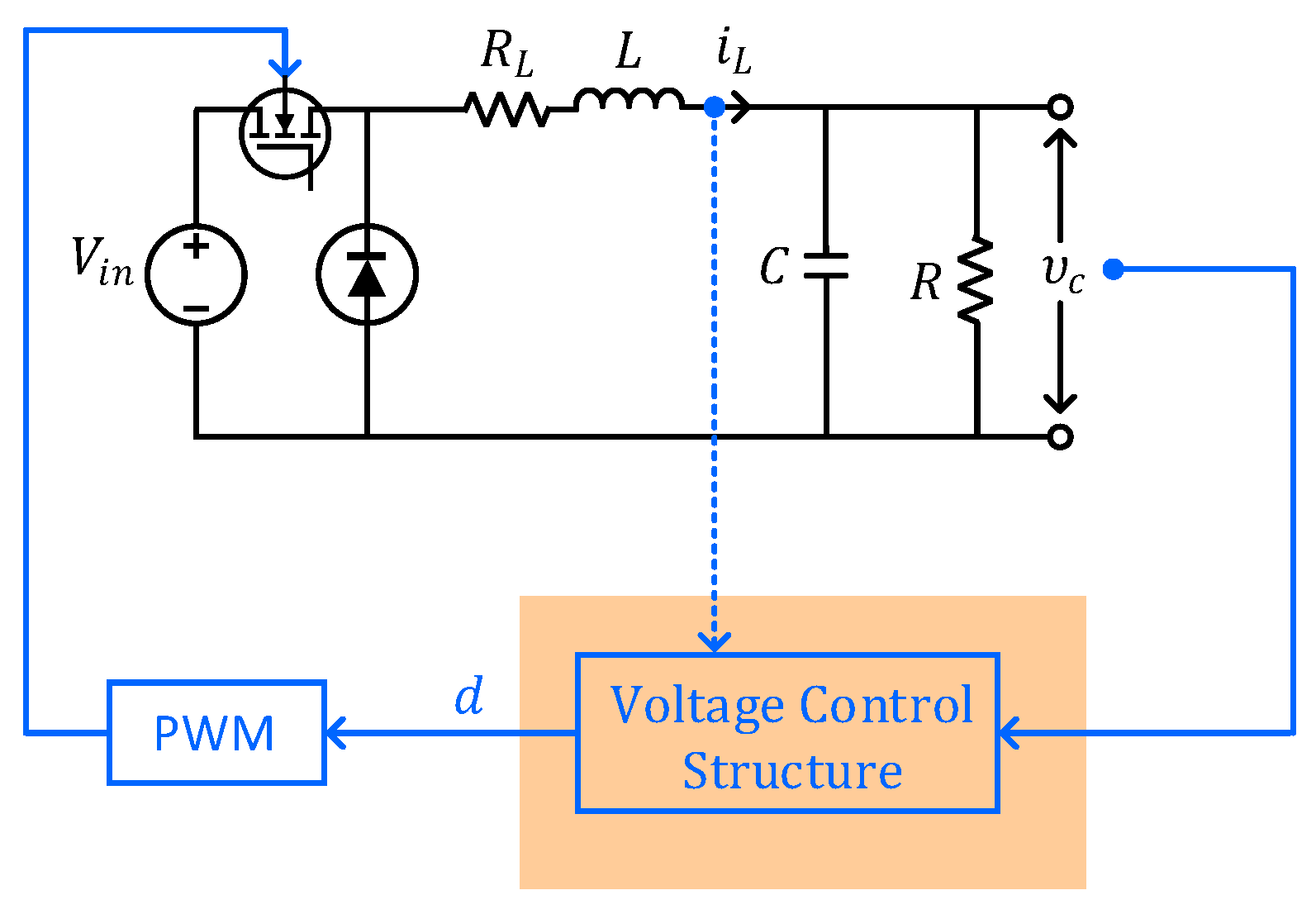
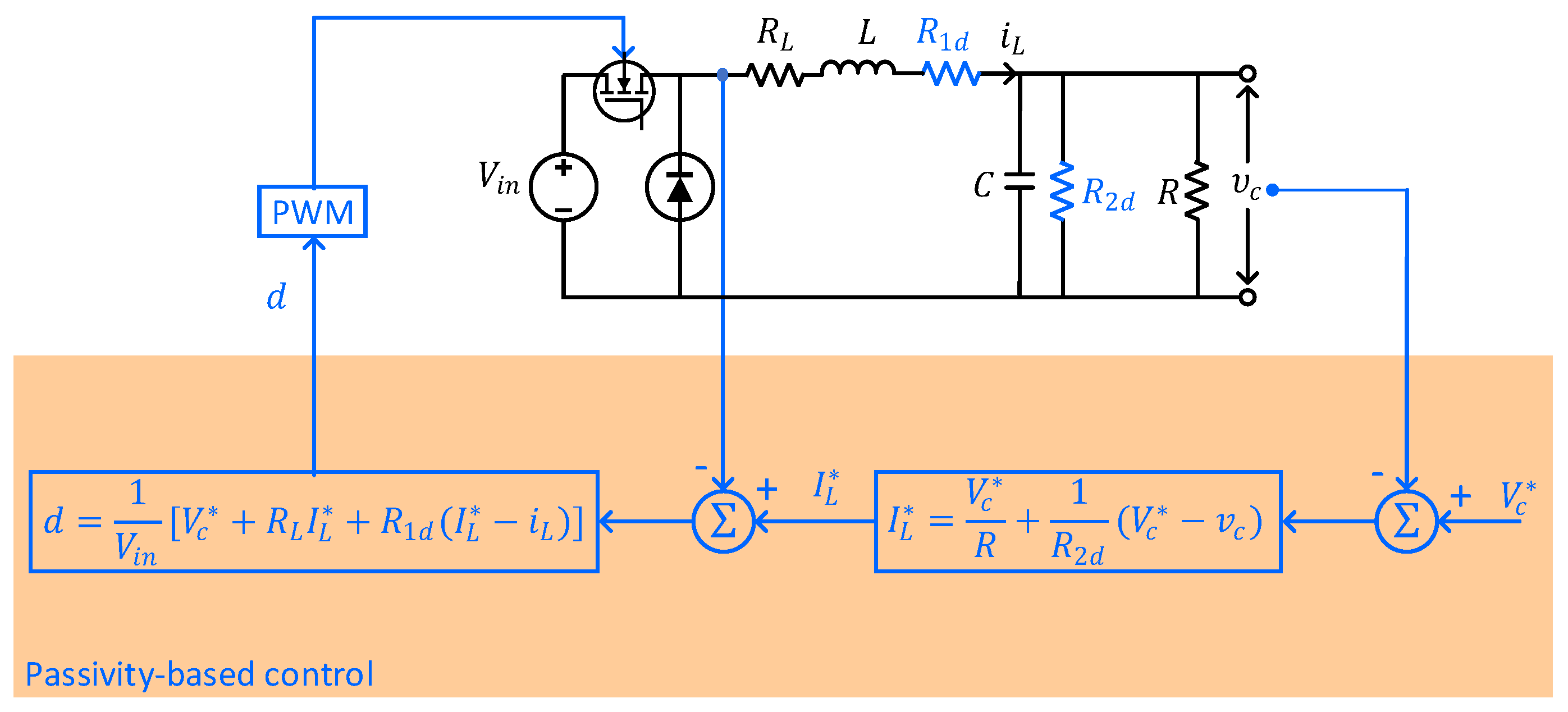
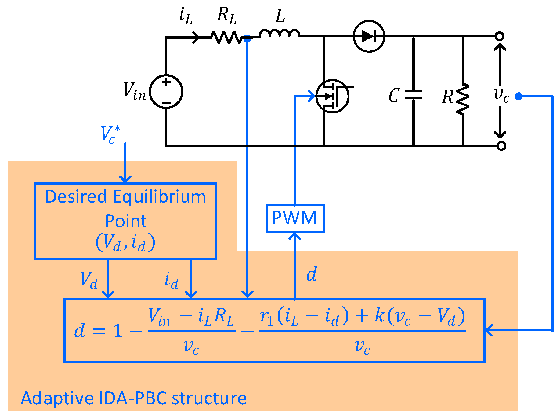
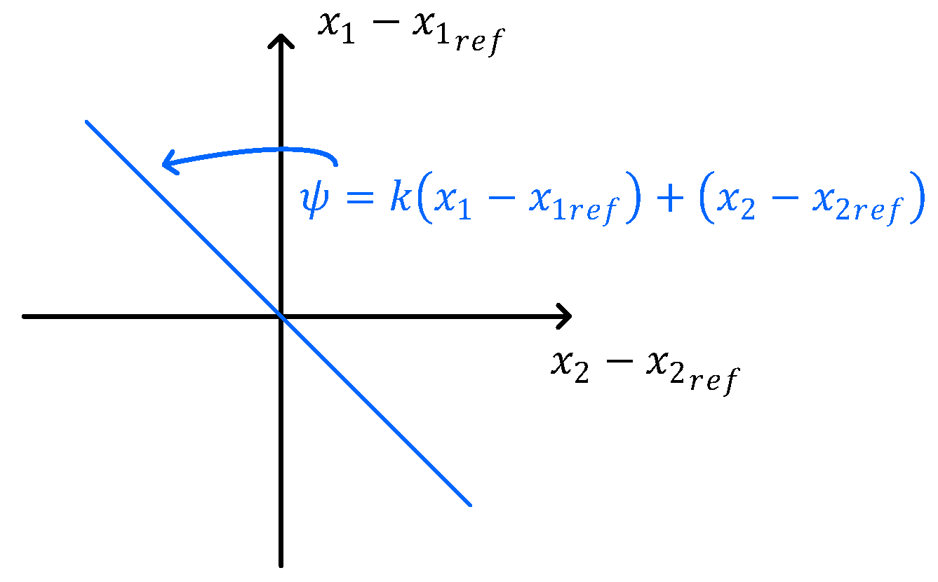
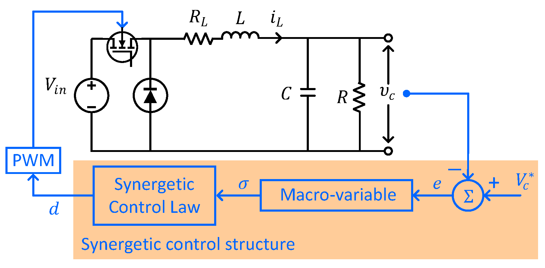
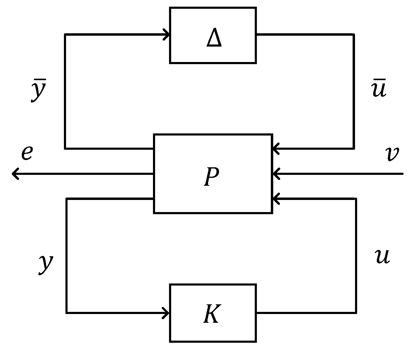
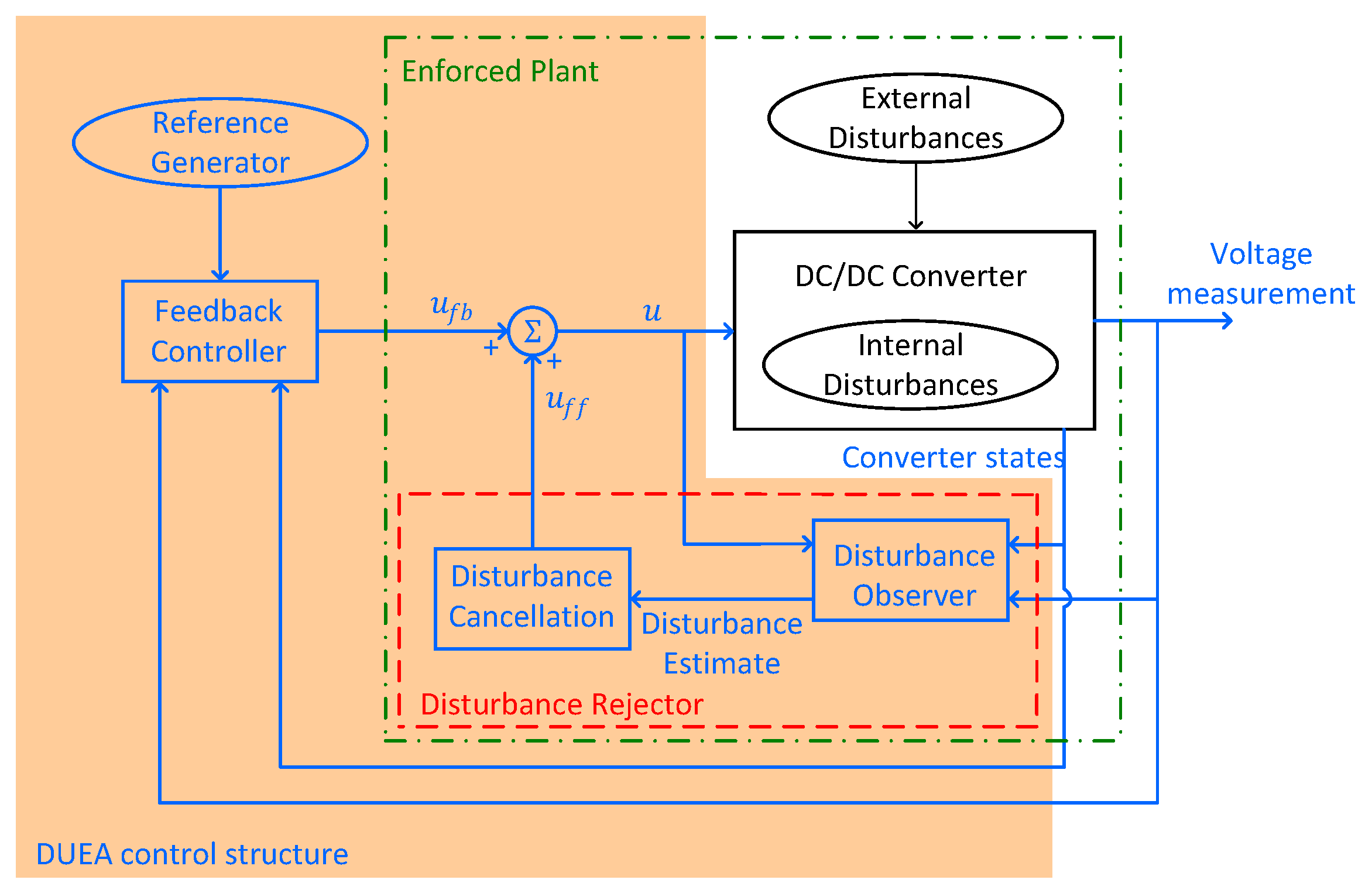
Table 1.
Addressed issues in other review papers and contributions of this work.
| Review Paper | Addressed Issues | Contributions of This Work |
|---|---|---|
| [27] | control methods formulated for specific load | control methods for any load |
| [28] | specific converter type with certain control objectives and practical restrictions | control design for general objectives and practical restrictions applied in DC/DC converter types |
| [29] | methods for power flow control | methods for voltage control |
| [30] | general strategies for feedback and feedforward control | specific models of control methods |
Table 2.
Feedback control methods for voltage regulation in DC/DC converters.
| Feedback Control Method | Advantages | Limitations | References of Applications |
|---|---|---|---|
| Lyapunov control |
|
| Buck/boost: [32] Cascaded boost: [33] |
| PBC |
|
| Buck: [39,42,43,44,46] Boost: [38,40,42,45,46,49] Buck/boost: [48] |
| Feedback linearisation |
|
| Boost: [41,51,55] Buck/boost: [52,53] Cuk: [54] |
| Backstepping control |
|
| Buck: [63,69,70] Boost: [60,61,62,65,66,73], [68,71,72,74] Buck/boost: [68,72] N-phase IDD boost: [64] Floating dual boost: [67] |
| SMC |
|
| Buck: [89,95,96,97,99,101] [84,98] Boost: [81,82,86,88,90,102] |
| Synergetic control |
|
| Buck: [63,107,113,115], [116,117] Boost: [104,105,110,112], [111,114] |
| LQR/LQG |
|
| Boost: [122,123,124,125], [127,128,134] Cuk: [120,121] X-converter: [126] Three-port isolated: [132] Two-switch forward: [135] |
|
| Buck: [63,140,142] Boost: [139,143] Multi-input converter: [141] LLC resonant: [138] | |
| MPC |
|
| Buck: [156,157] Boost: [150,154,155,158] |
Table 3.
Adaptive control applications for the voltage regulation in DC/DC converters.
| PBC | Backstepping | SMC | Synergetic | MPC | |
|---|---|---|---|---|---|
| [45,46] | [68,69] [70,71] | [73,86] [87,98] | [115,116] [117] | [140] | [158] |
Disclaimer/Publisher’s Note: The statements, opinions and data contained in all publications are solely those of the individual author(s) and contributor(s) and not of MDPI and/or the editor(s). MDPI and/or the editor(s) disclaim responsibility for any injury to people or property resulting from any ideas, methods, instructions or products referred to in the content. |
© 2023 by the authors. Licensee MDPI, Basel, Switzerland. This article is an open access article distributed under the terms and conditions of the Creative Commons Attribution (CC BY) license (https://creativecommons.org/licenses/by/4.0/).
Share and Cite
MDPI and ACS Style
Korompili, A.; Monti, A. Review of Modern Control Technologies for Voltage Regulation in DC/DC Converters of DC Microgrids. Energies 2023, 16, 4563. https://0-doi-org.brum.beds.ac.uk/10.3390/en16124563
AMA Style
Korompili A, Monti A. Review of Modern Control Technologies for Voltage Regulation in DC/DC Converters of DC Microgrids. Energies. 2023; 16(12):4563. https://0-doi-org.brum.beds.ac.uk/10.3390/en16124563
Chicago/Turabian StyleKorompili, Asimenia, and Antonello Monti. 2023. "Review of Modern Control Technologies for Voltage Regulation in DC/DC Converters of DC Microgrids" Energies 16, no. 12: 4563. https://0-doi-org.brum.beds.ac.uk/10.3390/en16124563
Note that from the first issue of 2016, this journal uses article numbers instead of page numbers. See further details here.