1. Introduction
In the context of growing energy demand in various industries, the global importance of electricity production and its efficient distribution cannot be overestimated [
1,
2,
3]. Numerous methods and technologies have been proposed to produce cost-effective energy, encompassing not only conventional approaches, but also alternative energy sources [
4] and unconventional energy acquisition methods [
5,
6]. A particular emphasis is placed on renewable energy sources and technologies [
7,
8], aligning with the contemporary requirements for environmentally responsible industries and the increasing prominence of green energy. These endeavors collectively promote the sustainable progression of the power engineering sector [
9,
10,
11].
The use of modern research techniques, including information technology [
12,
13], enables the development of high-quality, efficient electrical equipment and devices [
14,
15,
16]. The use of mathematical models plays a key role in shaping modern product development [
17,
18].
A significant part of power engineering-related research focuses on the initiation of various engines [
19,
20,
21]. This article discusses the use of frequency-dependent models for optimizing the equipment performance in isolated power systems.
Starting high-power asynchronous motors causes a significant voltage drop in the supply busbars. In isolated power systems, where the inertia of generators cannot be disregarded, it is imperative to consider the decrease in the rotational speeds of synchronous machines and the ensuing frequency decline in the system. Under such circumstances, the likelihood of erroneous trips in differential protection and motor start-up failures become significant.
2. Materials and Methods
For technical reasons, the direct-on-line starting method, which initiates powerful induction machines with maximum starting currents, is a requirement. Reducing the supply current frequency positively impacts the motor’s starting performance. This is primarily because motor impedances, currents, and torque are profoundly influenced by the system frequency. These dependencies are represented as follows:
Rr and
Xr denote the rotor resistances and reactances, and
Rs and
Xs signify the stator resistances and reactances, respectively [
22,
23].
Additionally, the starting power factor for robust induction machines is frequently set at 15% [
24,
25].
The highest modeling accuracy can be achieved by using software that includes instantaneous current values for calculations [
26,
27,
28,
29,
30]. However, such programs, like EMTP or PSCad, necessitate extensive input data that cannot be acquired during the design phase. In practical applications, software that computes transients in effective values is employed, such as ETAP [
31]. This software typically does not account for frequency deviation by default. This implies that induction motor impedances depend solely on the processes that occur during motor acceleration [
32,
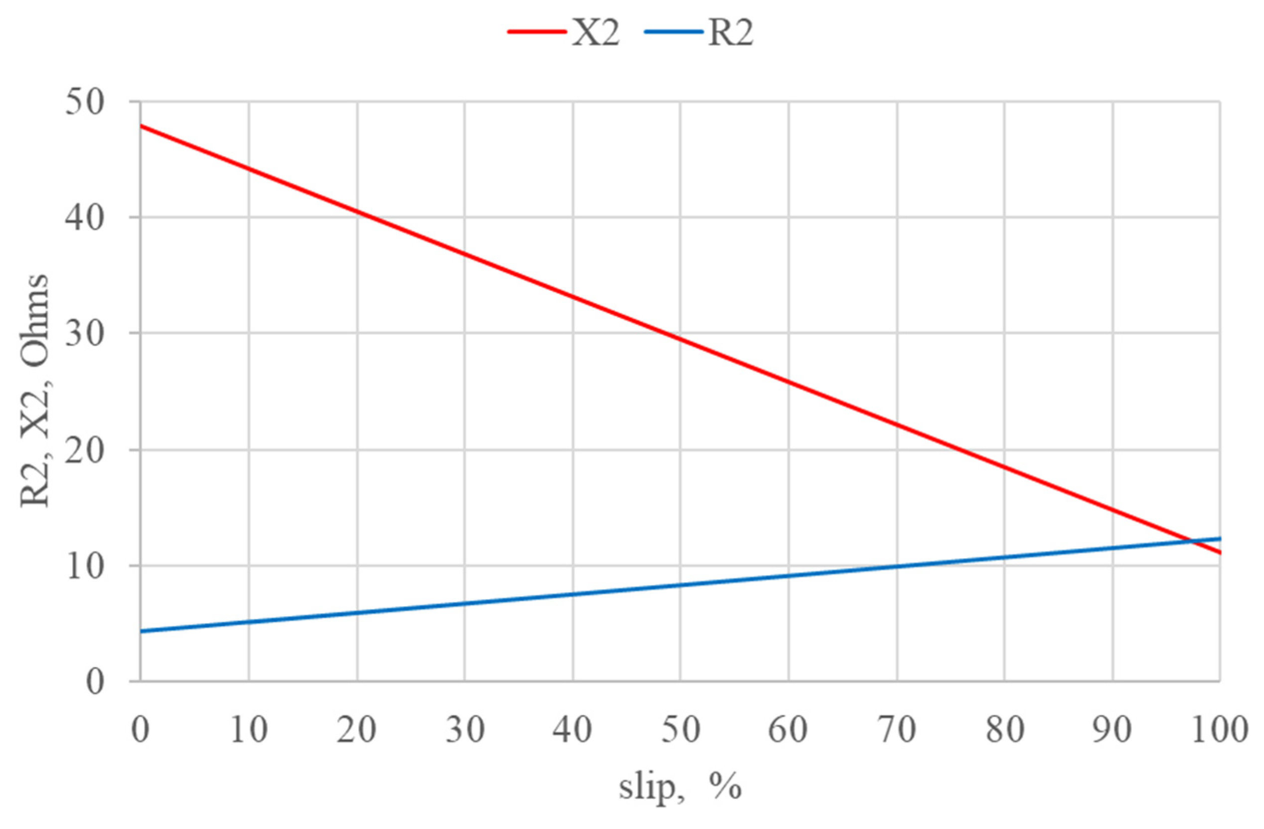
33]. These processes encompass changes in rotor resistance and reactance during acceleration, which are attributed to the deep bar effect:
Figure 1 illustrates the dependencies of rotor resistance and reactance on a slip for a generic 10 kV induction machine with a rated power of 200 kW.
Given that the majority of induction motors in use today are NEMA types B and C (as shown in
Figure 2), it is essential not to disregard the deep bar effect.
Isolated power systems, such as offshore oil rigs, necessitate the consideration of generator rotational frequency. Frequency-dependent machine models are employed for this purpose. These models posit that the machine’s electromotive force (EMF) remains independent of the busbar frequency, unlike the machine’s impedances. In this context, a vector of frequency values is constructed, which are defined as follows:
where
where
represents the vector of the frequency at system buses;
is the network susceptance matrix, representing the imaginary part of the standard network admittance matrix;
– n × m represents the susceptance matrix obtained using the stator and step-up transformer impedances of the synchronous machines;
n ×
n represents the diagonal matrix considering the internal susceptance of the synchronous machines at the generator buses [
34].
In fact, the process resembles frequency starting using a variable frequency drive (VFD), which has a positive impact on motor initiation.
When the frequency falls below its rated value, the motor’s starting current decreases insignificantly due to the varying of the stator and rotor impedances. However, the starting torque, which is directly proportional to the frequency in the first degree, increases significantly, as represented by the formula:
where
Starting induction motors with full loads exert the most strain on the power system. Reducing the supply busbar voltage in such systems diminishes the starting torque of the induction machines, while compromising their starting performance [
35,
36,
37,
38]. Conversely, lowering the voltage frequency helps mitigate the adverse effects of voltage reduction:
where
In transient simulations, alongside equations describing the electrical aspects of the machines, the differential equation governing rotational motion for all rotating machines is also solved. This equation aids in characterizing the transient behavior of rotating machinery:
where
—electric machine rotor speed derivative;
—machine inertia;
—machine total shaft torque [
31].
For induction machines, the total shaft torque can be written as
where
—induction machine electromagnetic torque;
—load torque.
This equation helps to describe the transient in terms of mechanics for rotating machines.
The variable J in this equation characterizes the moment of inertia of the rotating machine. In specifications compliant with modern industry standards, inertia may be specified by the manufacturer in various forms, including:
J—machine inertia, which is explicitly stated in kg·m2 or kgf·m2;
GD2—machine flywheel moment, which is specified in kg·m2, t·m2, or kgf·m2.
Regardless of the form where the flywheel moment is specified, it is related to the machine inertia as follows:
If the flywheel moment is specified in tons or tf, it must be converted to kilograms or kgf. Moreover, the manufacturer can provide initial data for machine inertia in WK2. In this case, the flywheel moment is still represented, but the equivalent rotor radius is used for this calculation, not the actual rotor radius, as in the case of the GD2 value. This way, WK2 will be equal to the machine inertia J.
However, during transients simulations using modern software packages, the constant of inertia
H is used more widely. The transition from the moment of inertia to the constant of inertia can be carried out in many different ways, but ETAP uses the following relationship to switch between these characteristics:
where
S—machine full-rated capacity in MVA;
n—rated speed in rpm;
J—moment of inertia in kg·m2.
In the context of the current study, the parameters of rotating machine inertia cannot be overlooked, as there is no connection to infinite power busbars, and power reserves are quite limited in isolated power systems. The equations presented above illustrate that machines with less inertia require less time to accelerate and decelerate. In contrast, more powerful and massive machines take longer to change their state (
Figure 3). Consequently, the operation of rotating machines in isolated power systems heavily relies on their inertia.
This article discusses the impact of utilizing frequency-dependent models during the direct-on-line starting of squirrel cage induction motors.
3. Results
We used ETAP 20.6 to compare the motor starting parameters obtained using frequency-dependent and frequency-independent models. To cross-reference the results, we established the grid illustrated in
Figure 4.
In this case, the synchronous generator is a two-pole machine with a rated voltage of 0.4 kV. Its performance parameters are detailed in
Table 1.
Additionally, there are two induction motors with different rated power levels, as shown in
Table 2. Their equivalent-circuit models were derived using the internal ETAP feature, which permits the parameter estimation of induction motors based on their nameplate data. As for the mechanical load characteristic, we employed a dynamic model representing a closed valve for both motors. This model is considered to be the most common; hence, it represents a lightly loaded case study. The variation in load torque depending on the machine speed was also taken into account during the simulation.
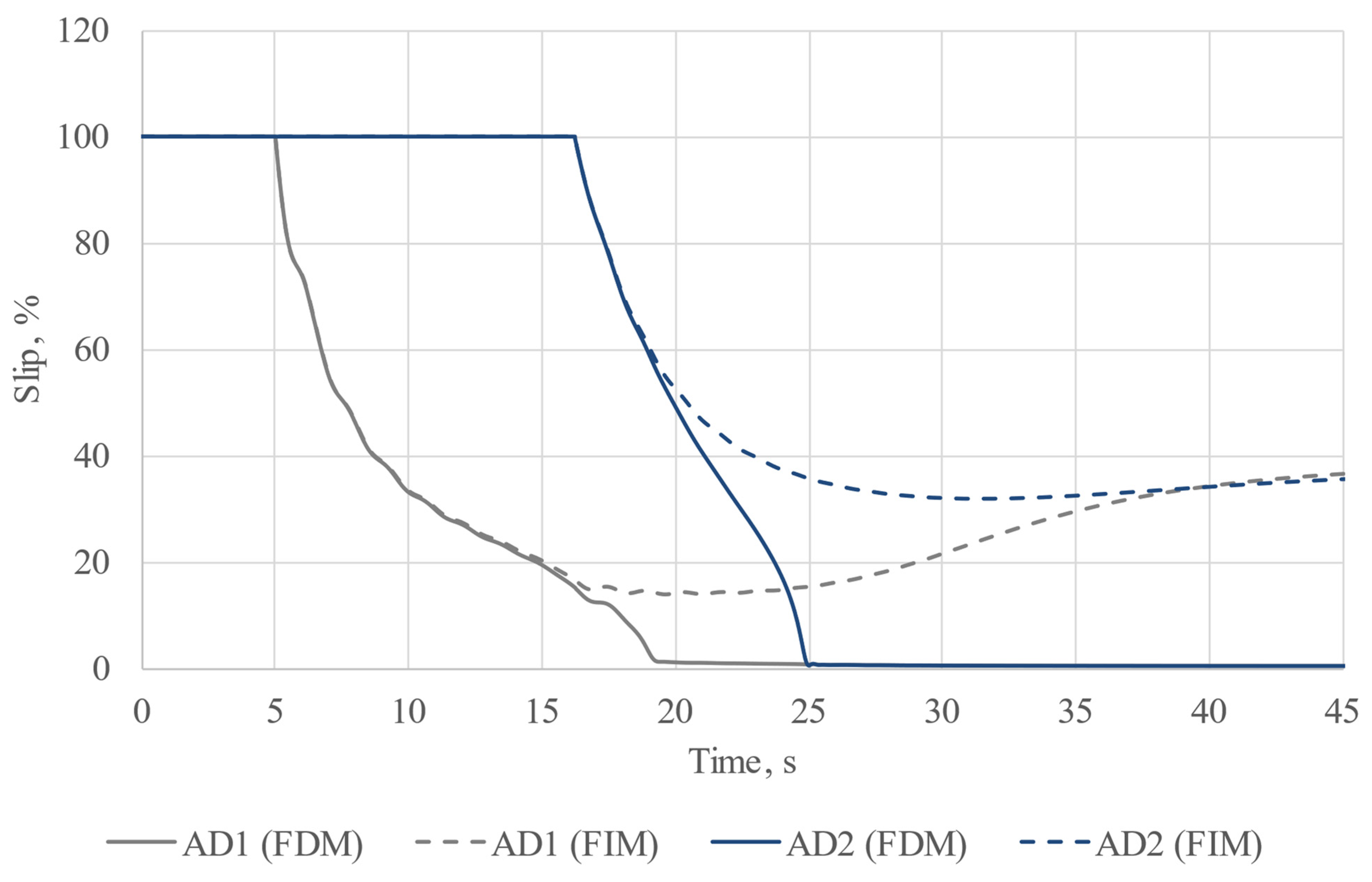
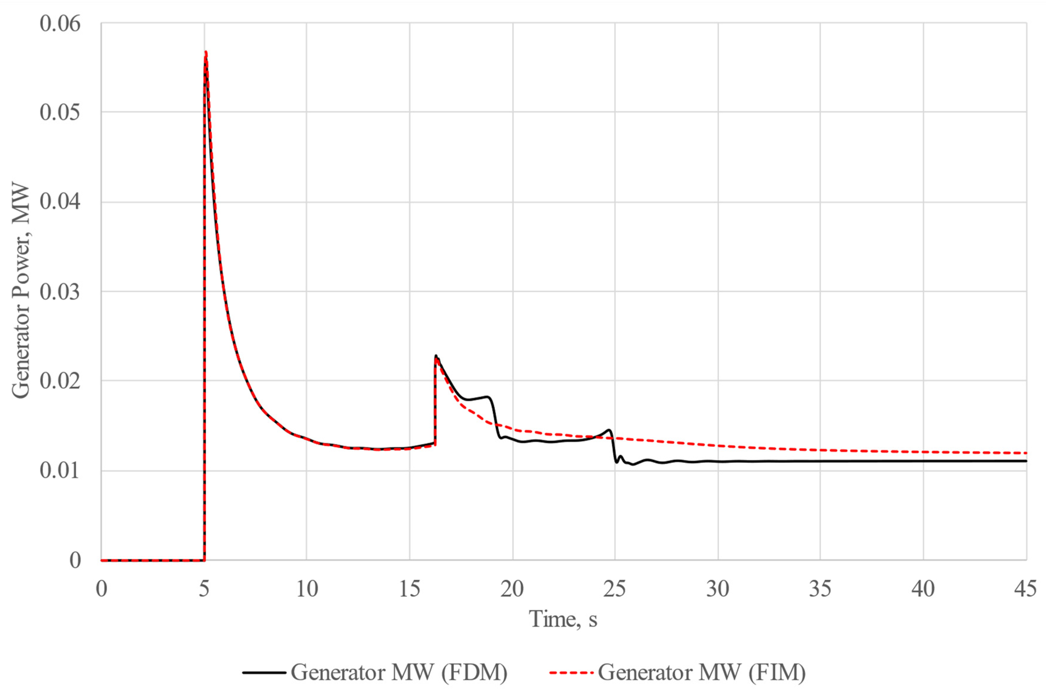
To assess the feasibility of direct-on-line motor starting, we conducted two experiments. In the first experiment, we employed a frequency-independent model, as this is the most typical scenario for conducting calculations. In the second experiment, we utilized a frequency-dependent model for the entire grid. In both experiments, motor starting was organized step by step. The most powerful motor was started 5 s after the commencement of calculations, while the second machine was started during its acceleration. In both experiments, the starting time for the second motor was set at 16.23 s after the initiation of calculations. The results of the experiments are depicted in
Figure 5,
Figure 6,
Figure 7,
Figure 8 and
Figure 9, with results for the frequency-independent model (FIM) depicted with dashed curves and results for the frequency-dependent model (FDM) represented with solid curves.
According to the results, significant improvements in the starting conditions for induction machines were observed when frequency-dependent machine models were employed. Reducing the frequency facilitates easier and faster motor acceleration, suggesting that even a slight reduction in system frequency during motor acceleration can greatly enhance direct-on-line starts for high-power industrial induction machines.
In order to perform such acceleration, it was necessary to adjust the generator rotor speed. In case of synchronous machines, their rotor speed is changed and maintained using a governor model. In previous experiments, we utilized a UG8-type governor, which is a common solution for modeling diesel generator units. The mathematical model of the UG8-type governor is depicted in
Figure 10.
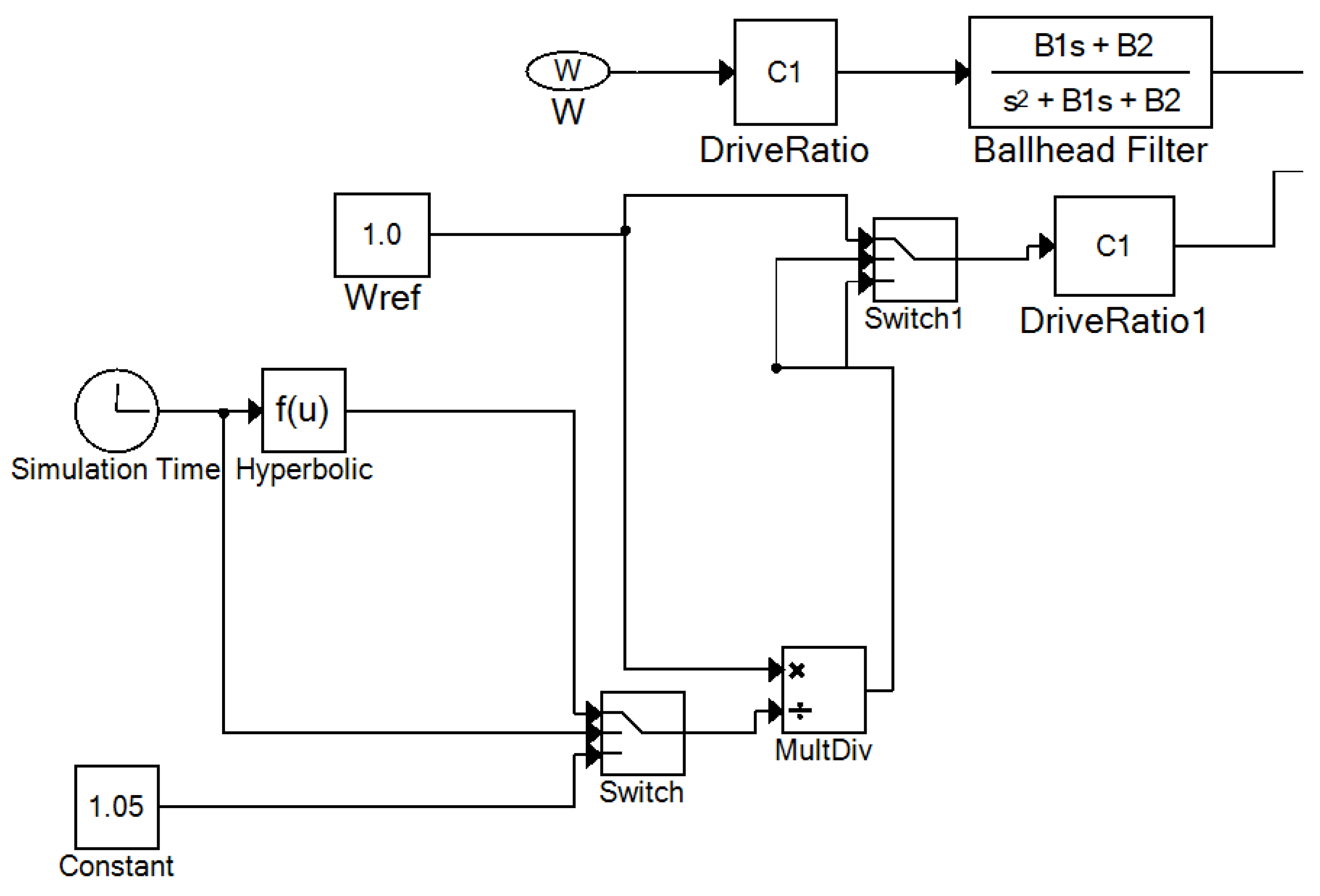
Within the ETAP software package, the governor model is defined using a built-in model editor employing FBD (Function Block Diagram) machine language. The ETAP representation of the UG8-type governor is shown in
Figure 11.
To implement motor acceleration at a reduced system frequency, we opted to directly manipulate the Wref parameter. This parameter establishes the reference generator speed for regulation purposes. The proposed method for motor acceleration entails reducing the generator rotor speed to 95% of its nominal value during acceleration, followed by a return to normal operation after the successful acceleration of all the motors. To maintain such an operational mode, the Wref parameter should be adjusted as illustrated in
Figure 12.
The proposed plot was determined using a piecewise defined function. To ensure the reduced generator speed was maintained during the induction motors’ acceleration, the value of Wref parameter was reduced to 0.95, which corresponds to 95% of the nominal generator rotor speed. This value was maintained by the governor during the whole transient process. After the motor was successfully accelerated to restore the rated speed of the generator, the parameter Wref was increased using a hyperbolic function until it’s value reached one; after that, it was maintained at this point until the end of the experiment. The Wref parameter change function was chosen to be hyperbolic as it was determined via a number of experiments as the most optimal one.
In order to meet the above-mentioned conditions, it was necessary to introduce additional variables into the original governor model, which allowed the algorithm shown in
Figure 13 to be executed.
Due to the specifics of ETAP software package operation, it was not possible to directly vary the Wref parameter value. Thus, in order to implement changes in the governor operating logic, it was necessary to introduce an additional parameter Kwref into the model, which will be a multiplier for the initial Wref parameter. The introduced variable is imaginary, so it was not directly integrated into the model.
In the presented algorithm, the first condition is directly related to the simulation time; the change in state occurred at a given time when motor acceleration was successfully finished. The second state was determined via an overshooting check, which should be carried out in order to prevent Wref exceeding value of one and maintain this value until the end of the experiment.
According to the above-mentioned data, we implemented a new subroutine into the default governor model, as shown in
Figure 14.
After the implementation of the modifications, the model was saved in .udm format. In order to verify our hypothesis about the improvement of starting conditions for induction machines during acceleration at a reduced system frequency, we carried out an additional experiment on the basis of the already considered model. The study conditions were left unchanged, but this time, we compared the results of experiment using frequency-dependent machine models and a default governor model with the results of the experiment using frequency-dependent machine models and a modified governor model. The results are shown in
Figure 15,
Figure 16,
Figure 17,
Figure 18 and
Figure 19. The dashed lines represent the results obtained from the experiment using the default governor model.
4. Discussion
According to the results [
39] of the experiment involving the frequency-independent model, it can be stated that the motors were unable to start, and the final slip value of the motors “hovered” at about 38%. This is due to the fact that during the start-up, the asynchronous motor puts a substantial load on the grid it is connected to, requiring large amounts of power it consumes in the normal operating mode. Step-by-step motor start-up also puts a large load on the generator because during the start-up of the first machine, there is a generation impact on the second stage of motor acceleration. This is evidenced by oscillations of the generator, which can be observed on the load bus frequency oscillogram. Still, these oscillations tend to fade as the calculations are being carried out. It can be clearly seen that the oscillations we observed during the start-up of the first motor are much greater than the oscillations observed from the start-up of the second motor. We believe this is due to the fact that the second motor has lower rated power in comparison to that of the first one.
The results we obtained from the experiment involving the frequency-dependent model differ a lot. From the solid curves, it is clear that there was a successful start-up of both motors. It is considered that the common induction motor start-up time rarely exceeds 4–5 s, so, in our case, the start-up was quite delayed. In such cases there is a serious risk of the motor windings overheating or the false tripping of relay protection. It is, however, worth mentioning that it has been experimentally revealed that the greatest differences in the experiment results using different models take place during long transient processes accompanied by great voltage drops. It is also worth mentioning that such transients are possible only in isolated power systems, where there is no connection to infinite power busbars with a constant frequency, which does not really change during motor start-ups.
From the oscillograms of load busbar voltage and system frequency, which represent both the synchronous generator rotor speed and voltage frequency on the load busbar, it can be seen that there was serious drop in both voltage and frequency. In this case, we can conclude that the direct-on-line start-up was successful due to the fact that slowed generator and decreased voltage worked like a kind of VFD and made the start-up possible.
As we have already mentioned above, induction motor acceleration is extremely difficult for isolated power systems due to the high locked rotor currents of the motors. A variety of measures can be used to improve the starting conditions: implementing soft starters and variable frequency drives, undervoltage acceleration, and star-delta accelerations. In this paper, we have proposed a reduced system frequency induction motor acceleration method which does not involve using additional equipment.
Undervoltage induction motor acceleration, whether using a transformer or current limiting resistor, involves the inevitable reduction locked rotor torque of motors based on the fact that the torque at a reduced voltage can be calculated as follows:
Reduced locked rotor torque leads to longer induction motor acceleration. This also increases the risk of machine stalling if the load torque appears to be greater than the locked rotor torque. In isolated power systems, this acceleration method can pose a serious risk to the technical process. In addition, such acceleration requires the use of additional equipment, which reduces the reliability of the whole system. Additional switching operations can also be required, which increases the human role. Our proposed method significantly simplifies motor acceleration, while the locked rotor characteristics are practically unchanged, which also improves the stability.
In the case of using soft starters and variable frequency drives, the locked rotor characteristics of asynchronous motors remain at a nominal level. The most important locked rotor characteristic, machine torque, at a reduced frequency can be calculated as follows:
Despite the fact that locked rotor characteristics remain unchanged, the use of soft starters is rather limited in isolated power systems due to the high prices for such equipment. This leads to an increase in costs at the design stage and a decrease in the reliability of induction machines’ feeders, which is undesirable. As we have already noted above, an important aspect for isolated power system is the preservation and maintenance of a reliable technical process. Despite the fact that the method proposed in this paper does not allow us to achieve the same efficiency as soft starters, still, the efficiency is comparable, but our method does not involve additional costs, and there is no decrease in the power system reliability.
The delta-star switching acceleration method can reduce the acceleration consequences and deload the generating equipment only slightly. This acceleration method is used selectively for the most powerful machines in order to soften their start-ups when they do not need to be started or stopped frequently. At the moment, its application is seriously limited, due to its low efficiency. The method we propose in this paper has a much higher efficiency and can be applied to all motors that require acceleration since it is related to generator regulator operation.
The proposed acceleration method turned out to be the most preferable for isolated power systems, as it is superior to the above-mentioned methods in one or another way. The experimental results show a significant improvement in the acceleration conditions in comparison with those of conventional direct-on-line motor acceleration. Future research is required in order to compare the methods with each other more accurately. However, at this stage, we can assume the high relevance of the proposed method for isolated power systems. Also, for the final confirmation of its performance, it will be necessary to carry out a practical test, but its effectiveness can be judged using data from already conducted studies.
The results of induction machines acceleration at a reduced system frequency show that it is possible to significantly improve direct-on-line induction motor starting in isolated power systems. The application of the proposed method allowed us to reduce the acceleration time of the most powerful motor AD-1 by about 37% and by about 16% for AD-2, and the overall acceleration time was reduced by about 25% in comparison with that of the ordinary direct-on-line start-up. Furthermore, the oscillograms show that the frequency and voltage distortions are less distinct during the reduced system frequency motor acceleration in comparison with those of the direct-on-line motor start-up.
Traditionally, the transients associated with induction motor acceleration and re-acceleration are considered as equivalent to those of a short circuit. In such case, each individual motor acceleration is considered. The circuit is equivalented, the motor is considered as a voltage source and its impedance, and the system is considered as a voltage source and equivalent impedance of all the system elements reduced to the motor connection point. In this case, the locked rotor current of an induction motor is taken as a “short-circuit current”, and the point of the calculation is to determine the residual voltage on the machine terminals. Acceleration and re-acceleration are considered successful if the residual voltage exceeds 70% of the nominal value; otherwise, acceleration will be considered unsuccessful, and a stall will occur.
In the case of acceleration success evaluation using the method described above, only the locked rotor current is taken into account when modelling an induction motor. Both the processes occurring in the machine, such as the deep bar effect, and the influence of the system parameters on the acceleration process were not taken into account since the supply voltage and frequency may change significantly during acceleration in an isolated power system. In addition, this method does not take into account the machines’ mechanical properties, such as the inertia of the machine rotor and the inertia of the mechanism that is being driven by the motor. Thus, this estimation method is relatively inaccurate, but it can be used to quickly estimate the result of acceleration or re-acceleration.
For a more detailed estimation, a calculation using numeric integration can be applied. This type of calculation takes into account both the machine and mechanism mechanical characteristics and a number of processes that occur during acceleration. The difficulty of this calculation method is that it ought to be performed for each motor individually. The acceleration or re-acceleration estimation of a group of motors would require a number of calculations, which is quite a laborious task. It is also impossible to totally take into account the full influence of operating parameters on the acceleration process, as often the models used for manual calculations assume that these parameters remain constant during the transient process.
The evaluation of transient processes via computer modelling presented in this paper allows us to solve most of the problems noted for the methods mentioned above. Computer modelling enables us to obtain more accurate results in comparison with those of the above-mentioned methods due to the use of more detailed models of machines, taking into account both their mechanical characteristics and operating parameters of the whole system. The frequency-dependent machine models used in our calculations tend to give more detailed results in comparison with those of the above-mentioned calculation methods. In addition, a computer calculation technique implies analyzing not a single operating mode, when some parameters are assumed to be constant, but a quasi-stationary operating mode using specified machine models described in the IEEE standards. This approach to modelling allows us not only to consider operating parameters influence on motor acceleration, but also to take into account the operation of generators control systems, which is often too complex for manual calculation methods. The use of computer modelling for transients’ analysis in power engineering allows us to study them dynamically and analyze the power system state at any moment during the simulation, which is impossible in case of using manual modelling methods, and their usage can lead to incorrect power system operation assessment. At the same time, computer modelling significantly simplifies and accelerates the calculations, which is especially important in the case of analyzing large power systems, while maintaining the high accuracy of calculations. This is of great relevance for the modern industry.
5. Conclusions
In this paper, we carried out experiments on an isolated power system using frequency-dependent and frequency-independent machine models. We discovered that there are cases where the simulation result heavily depends on the model type being used. The data acquired during the simulations show that the methods commonly used to estimate the success of motor acceleration can be rather rough. The criterion which involves residual busbar voltage estimation is not desirable for use even in the approximate analysis of motor acceleration. The experimental data show that, in some cases, there is a possibility for induction machines to accelerate successfully even if the residual voltage is lower than 70% of the rated level. The use of a frequency-dependent model allows the more accurate simulation of the processes that occur during induction motors start-ups because, in this case, the calculation takes into account changes in the impedances of elements depending on the system frequency. With this approach, the dynamic simulation of transients in electric power systems can be carried out. This is the main advantage of the frequency-dependent power system model. As a result, it is possible to save up funds that are being spent to buy equipment because there is an opportunity to avoid buying additional generators and soft starters. The implementation of frequency-dependent models into the design processes of isolated power systems can increase the injectivity and flexibility of such systems, as it is possible to provide more favorable starting modes of induction machines without involving additional devices and systems. Thus, the result of using frequency-dependent models in calculations is a more accurate and complete understanding of how the capacity of existing equipment is used in isolated power systems, which leads to the optimization of the operational modes of this equipment.
Direct-on-line induction machines starts are considered to be one of the most stressed operating modes, especially in isolated power systems. A number of measures can be taken as a solution to help unload the generating equipment, and among them are, using soft starters and variable frequency drives, using resistors to limit current, and using the so-called start-up with star-delta winding switching. The main disadvantages of these methods are that they require expensive equipment and are less reliable (for soft starters and variable frequency drives) and ineffectively determine the motor starting characteristics (for resistors and star-delta starting).
As a result of the experiments, we found that there is a theoretical possibility of providing direct-on-line start-ups for powerful induction machines in isolated power systems. Direct-on-line start-ups can be provided by reducing the generator rotor speed and causing a slight decrease in voltage on its terminals. In this case, we can employ partial frequency starting for induction motors. The use of the proposed acceleration method makes it possible to significantly reduce the acceleration time of induction machines along with the loading of the generating equipment.
The study we carried out in this paper shows the importance of computer modelling using frequency-dependent models during the design and operation procedures of existing power systems. This approach results in the optimization of equipment utilization within the power engineering industry.

 ,
, 


