Article

Development of a Model-Based Coordinated Air-Fuel Controller for a 3.0 dm3 Diesel Engine and Its Assessment through Model-in-the-Loop

1
Energy Department, Politecnico di Torino, 10129 Torino, Italy
2
Department of Electronics and Telecommunications, Politecnico di Torino, 10129 Torino, Italy
*
Author to whom correspondence should be addressed.
Submission received: 24 November 2022 / Revised: 10 January 2023 / Accepted: 10 January 2023 / Published: 13 January 2023
(This article belongs to the Special Issue Trends and Prospects in a New Generation of Engines and Powertrains)

Abstract

:
The tightening of diesel pollutant emission regulations has made Internal Combustion Engine (ICE) management through steady-state maps obsolete. To overcome the map’s scarce performance and efficiently manage the engine, control systems must cope with ICE transient operations, the coupling between its subsystem dynamics, and the tradeoff between different requirements. The work demonstrates the effectiveness of a reference generator that coordinates the air path and combustion control systems of a turbocharged heavy-duty diesel engine. The control system coordinator is based on neural networks and allows for following different engine-out Nitrogen Oxide (NOx) targets while satisfying the load request. The air path control system provides the global conditions for the correct functioning of the engine, targeting O 2 concentration and pressure in the intake manifold. Through cooperation, the combustion control targets Brake Mean Effective Pressure (BMEP) and NOx to react to rapid changes in the engine operating state and compensates for the remaining deviations with respect to load and NOx targets. The reference generator and the two controller algorithms are suitable for real-time implementation on rapid-prototyping hardware. The performance overall was good, allowing the engine to follow different NOx targets with 150 ppm of deviation and to achieve an average BMEP error of 0.3 bar.

1. Introduction

Today’s society is heavily dependent on logistics and the transport of goods and people. Currently, internal combustion engines still play a major role in the transport sector since almost all transportation is powered by them. Furthermore, 90% of the energy required in transport is extracted from liquid fuels derived from petroleum. All of this accounts for 25% of global Carbon Dioxide ( C O 2 ) emissions [1,2] and 10–15% of greenhouse gases, including emissions from land, air, and marine transportation [3]. In addition, emissions such as Particulate Matter (PM) and NOx are detrimental to human health. The main reason for the dominance and consequent large deployment of this technology since the beginning of the last century is the use of liquid fuels. Liquid fuels are exceptionally dense energy carriers, perfect for onboard storage, and allow long vehicle ranges with short refueling times. Moreover, the ICE is backed by a global infrastructure network, from the production refineries and refueling stations to the mechanics’ workshops. Further, modern ICEs, together with the vehicles they drive, are very reliable machines. However, increased environmental and health concerns due to the rise in global temperatures and ICE-emitted pollutants joined with an increased transport demand in recent years, have forced legislators to introduce regulations on C O 2 and pollutant emissions.
Emission regulations through the years have forced automakers to develop a wide range of technologies. Exhaust Gas Recirculation (EGR) and Variable Geometry Turbochargers (VGTs) [4], high-pressure common rail injection systems [5,6], advanced combustion control [7], alternative combustion concepts [8,9], and alternative fuels [10] represent some of these technologies. However, due to the media and politicians’ slogans, a false belief that ICEs are old or even that they have not changed over the last century is perceived. On the contrary, ICEs have undergone significant changes as a result of engineering and technological improvements. Looking at fuel economy alone, there has been an increase of over 90% between 1975 and 2015 [11]. Furthermore, all these improvements took place together with performance enhancement.
However, the second drawback of ICEs consists in their relatively low efficiency, which is on the order of 40–50% for conventional engines or around the 50% considering modern hybrid powertrains [12]. Nevertheless, there are thermodynamic limits to efficiency, and it typically scales with size [13]. Overall, progress has been remarkable, but there is still much more work to do with stringent future regulations in place. To further improve ICE performance, advanced engine control systems are required, such as air path and combustion controllers. The optimization of these controllers can allow for fully exploiting the potential of the previously mentioned technologies in order to achieve the best trade-off between engine performance and emitted pollutants.
In addition, the importance of a coordinator between the air path and combustion controllers is paramount. Target signals for the two control systems have to be generated considering the different time dynamics and actual working conditions of the two systems. The main reason for the sometimes poor performance of the two control systems, working separately, is the mismatch between the actual and reference value of key variables used for target generation. The two controllers are independent, but the air path and combustion subsystems are strongly coupled, and, with this bias, the engine works in conditions that differ from the expected ones.
The aim of this work is to use MiL and Software-in-the-Loop (SiL) to develop and assess innovative algorithms for sensor-based and model-based control and coordination of the air path, combustion, and pollutants (NOx engine-out emissions). The main contribution to the literature is the management of these two engine-control systems through machine-learning techniques and models. More details on the approach proposed in this work can be found in [14].

2. Bibliography Review

Air path control is generally managed by means of Steady-State (SS) calibration maps. In these maps, the actuator’s position is stored as a function of the engine speed and load or the injected fuel quantity. The stored position is correlated to a desired air path state, usually expressed with the air mass flow rate and boost pressure. This approach represents an open-loop control strategy that is very simple to implement and intuitively requires very low computational time. However, this method requires considerable experimental time, which comes at a high cost, to build those maps. Additionally, a correction of the actuator position is not possible due to the lack of feedback. As a consequence, during engine transient operation, the air path’s actual state can deviate considerably from the expected one.
Among the available control structures, Proportional–Integral–Derivative controllers (PIDs) have been widely adopted in the industry due to their simplicity, and ICEs are no exception. The implementation strategy exploits the decoupling between the air mass flow rate and the intake manifold pressure. In this framework, two separate control loops based on PIDs are generally adopted for the air path: the Air Mass Flow (MAF) control loop, which is realized by acting on the EGR valve position, and the Intake Manifold Pressure (IMAP) control loop, which is realized by acting on the VGT valve position [15]. The PID coefficients are first tuned through simulations by means of Model-in-the-Loop (MiL), using black-box models or heuristic methods, and then refined at the test bench. To improve the performance of the controllers over the whole engine map, different values of the PID coefficients may be used depending on the engine operating point. These values can be stored in steady-state maps as a function of the engine speed and load. Feedback control often couples with feedforward action to deal with the influence of varying operating points. The feedforward contribution enables fast changes in operating points while the feedback controller performs the error compensation [16]. An extensive calibration of the controller is needed in order to guarantee optimum and robust engine performance for a broad operational range. Likewise, given that the air path is a complex nonlinear dynamical system, the previous approach (i.e., separate control of the MAF and IMAP) lacks effectiveness during transients. It has to be noted that these two control loops cannot work simultaneously in an efficient manner, as the PID is a single-input single-output linear control technique. The assumption behind the use of two separate control loops for the MAF and IMAP is that the EGR actuator has a stronger effect on the MAF than on the IMAP and vice-versa for the VGT actuator. However, a mutual influence is present and imposes limitations on the control design and performance. This translates into conflicting control actions during transients and deviations from the reference value. An example of this approach can be found in [15,17], while a scheme illustrating the approach is reported in Figure 1, where index ref indicates the reference values, prefix Δ the variations of the related signal, and u the actuator signals.
Multiple-Input Multiple-Output (MIMO) control techniques have also been employed to overcome limitations due to the coupling effect. Different solutions have been reported in the literature, such as eigenvalue placement [18,19], H and robust control [20,21,22], internal model structure [20], and sliding mode control [23]. All these multivariable approaches are difficult to set up since the structure of the air path dynamic models has to be explicitly accounted for in the definition of the control law. The avoidance of this complexity is one of the main reasons why Model Predictive Control (MPC) is becoming more and more popular in the ICE field. The quest for performance and emission requirement fulfillment led the number of control actuators to increase as new technologies made their appearance in the ICE, increasing the overall system complexity. Since the calibration of a high number of control actuators requires extensive activity at the test bench, optimization methods are generally employed to tackle this problem, which in turn requires suitable models. MPC has a very good potential for engine optimization tasks due to its capability to manage highly nonlinear and constrained systems, thus guaranteeing the desired behavior. However, its real-time employment is feasible using specialized solvers [24,25,26].
Two modeling strategies are generally employed to tackle the control problem through MPC. The first one uses an air path mean value model, while the second one exploits black-box models. In the latter case, two approaches can be adopted, i.e., a single nonlinear model or multiple linear/nonlinear combined models [18]. The last distinction is made concerning whether the MPC features online or offline optimization, the latter case referred to as explicit MPC. Explicit Model Predictive Control uses offline computations to determine all the operating regions in which the optimal control moves by evaluating an affine function of the state. For this reason, explicit MPC requires fewer run-time computations than traditional (implicit) MPC and is useful for applications requiring short sampling times. In contrast to their fast run-times, MPCs’ memory footprint is high as all the coefficients corresponding to each region have to be stored. Consequently, their use is limited to systems with a low number of inputs, outputs, and states.
The controller reported in [27] is based on the first approach, and regulates the air mass flow rate and the boost pressure by managing EGR and VGT actuators in a diesel engine running partially premixed diesel combustion. The control structure featured an MPC with a Kalman filter to compensate for the model mismatches. Abidi et al. [28] also developed a state-space diesel engine model to control VGT and EGR valves. In their approach, they neglected the inlet temperature to reduce computing effort to the detriment of the model’s accuracy. Moreover, several nonlinear functions were replaced by constant or linearized functions in the controller in order to enable its implementation.
Kim et al. [29] developed a fifth-order state-space control-oriented model with an input-output linearization technique for controlling the air path of a diesel engine with a dual loop EGR system. However, several simplifying assumptions were made for the controller design, such as excluding the burnt gas fraction, disregarding the temperature dynamics, and using a single value of temperature for each volume.
Concerning MPC exploiting black-box models, the most adopted structures are the regressive ones. The AutoRegressive model with eXogenous input (ARX) or, in the Nonlinear case, NARX Hammerstein, Wiener, and Hammerstein-Wiener models [30] are the families that are more often employed. These methods require the splitting of the engine map into different areas and the identification of a separate model for each region. The fundamental step of this approach is the experimental campaign to collect the data needed to estimate the models: a detailed guide can be found in [31]. In [32], twelve models corresponding to twelve engine map regions were identified and used in an MPC structure. The same approach was also applied to the fuel path.
In the literature, the most frequently studied fuel path control systems are cylinder pressure sensor-based combustion phasing and Indicated Mean Effective Pressure (IMEP) control [33,34]. The control structure is based on decentralized PID regulators forming two separate loops that actuate, for the main pulse, the injection quantity to achieve the IMEP target and the Start of Injection (SOI) to achieve the MFB50 target (the crank angle at which 50% of fuel mass has burned).
Cycle-to-cycle correction is the most implemented control strategy. It is realized by combining a feedforward action and a feedback loop; Figure 2 illustrates this control structure. The feedforward term is authorized to provide the nominal value for the control actuation to improve the transient response. At the same time, the feedback loop, generally PI or PID, corrects the command on the basis of the error with respect to the target value. In a cycle-to-cycle approach, the correction evaluated at combustion cycle k is applied to the next combustion cycle k + 1 . On the basis of the in-cylinder pressure measurement or estimation, feedback data, generally constituted by combustion metrics, are retrieved from the Heat Release Rate (HRR) analysis. A separate feedback controller is generally used for each cylinder. The feedforward path is mainly implemented through steady-state maps, even if there are examples in which radial neural networks are used, see, e.g., [35].
In [33], the MFB50 and IMEP were determined every cycle using a virtual sensor for the individual cylinders. Based on the detected error, the PI controllers adjusted the SOI and fuel quantity for the main pulse to achieve the desired MFB50 and IMEP values in the next cycle, respectively. Cylinder balancing was achieved by simultaneously running the six individual cylinder controllers with identical set points. The calibration of the controllers was done considering several step responses, with the goal of a response time of five cycles to meet 90% of the set-point value with a minimal cylinder-to-cylinder variation.
In [36], a dedicated PI combustion control loop was applied to each cylinder. All the loops managed fuel quantity and injection timing. S O I m a i n was controlled to target MFB50 and injected quantity q m a i n to target The load.
In [37], Carlucci et al. tried to improve the cycle-to-cycle closed-loop control by implementing a function that constrained the feedforward input of the main pulse timing before the closed-loop control intervention, depending on the current engine operating conditions. The correction is operated only in critical moments by freezing the last main pulse S O I m a i n from steady-state maps. In this state, the Electronic Control Unit (ECU) controller adds its correction to the frozen value instead of the SS map value as in normal conditions. In [38], a general framework is discussed that describes the combustion process on a cycle-to-cycle basis with parametrized fueling profiles. Based on a sensitivity analysis, a MIMO combustion controller is designed with a local stability guarantee. The controlled variables are the combustion metrics MFB50-70-90 and IMEP. The manipulated variables are the duration and SOI of each injection. The design of the control system uses the eigenvalue placement technique and is done by inverting the sensitivity function of each combination of parameters.
In [39], the control algorithm consists of three elements: a Kalman filter as an observer, a target selector used for the optimization of steady-state values, and a dynamic regulator for calculating the optimal actuated values, which are output to the plant. The dynamic regulator, which is based on a quadratic norm cost function, compensates for the coupled MIMO system dynamics. A Wiener-type dynamic was used to reproduce the premixed charge non-conventional combustion behavior. Then, a series connection of a linear dynamic term and a nonlinear static term (discontinuity) was incorporated to obtain a piecewise affine model. With this algorithm, a nonlinear optimization was performed at every time step, considering the task of tracking reference values and minimizing values, i.e., fuel consumption, such that the optimal combustion mode, conventional or not, was chosen automatically.
The controller reported in [35] consisted of a fixed feedback compensator that ensured the stability of the system and an adaptive feedforward controller, trained by the output signal of the feedback one, to improve the performance. The feedforward controller consisted of a radial basis function network with two inputs, engine speed and target start of combustion, and one output, the effective start of energizing. The linear controller calculates the start of energizing from the error between the target and the estimated start of combustion. The output of the linear controller, i.e., the start of energizing, is used to adapt the network. The architecture was extended to use only one network for all the cylinders while maintaining one linear regulator in each cylinder.
In [27], the engine load, represented by gross IMEP, was regulated by the main injection duration using dedicated linear feedback. MFB50 was used as the main combustion parameter to understand its development. Two pilot injections were controlled explicitly, depending on engine load and speed. The Arrhenius-type equation was used to model the ignition delay, which was then exploited to evaluate the combustion timing. The equations were stated to obtain a state-space formulation.
By looking at the literature, only a few examples of air path and combustion control systems coordinators have been found. In [36], the controllers were coordinated by a high-level structure that considered the combustion halfway point, maximum pressure, rate of combustion, combustion instability, and IMEP obtained from in-cylinder pressure measurement as states to generate the correct references. In parallel with the combustion control system, the air path controller targeted MAF and IMAP through the EGR valve and VGT.
In [40], a supervisory MPC that manages nonlinear controllers is developed for an air path system for multimode operation in a diesel engine. The whole controller includes three parts: supervisory MPC as target set point coordinator, actuator level nonlinear control, and state detection using either a virtual sensor or an ECU sensor. The actuator nonlinear control compensates for the error dynamics. In this study, the coordination dynamic is modeled with a set of first-order transfer functions. Only the MAF, intake O 2 concentration, and the O 2 concentration at the compressor inlet are considered.
In [27], a MPC regulates both air path and combustion in a diesel engine running partially premixed combustion. In the air path, MAF and IMAP are regulated through EGR and VGT actuators, while the combustion is managed through the main injection duration. The control structure features an MPC with a Kalman filter that compensates for the model mismatches. Still, the references for the target variables came from maps and models obtained using a sensitivity analysis.

3. Overall Control Structure

The engine considered in this work is a 3.0 dm 3 heavy-duty Euro VI diesel engine, and its main specifications are reported in Table 1. It is endowed with High-Pressure EGR (HP-EGR), EGR cooler, VGT, Exhaust flap, and Intercooler (Figure 3).
The engine has been equipped with an O 2 concentration sensor in the intake manifold. Even though, in this way, the engine complexity increases, the direct measurement allows for precise monitoring of the intake oxygen concentration. Furthermore, the acquired data can be exploited by dynamic models to obtain more precise output predictions [41].
In order to perform MiL tests, the engine has been modeled in the GT-suite environment. The validation of the developed model for the variables of main interest in the work is reported in Appendix A. Details on the test bench, in which the experimental data were acquired, can be found in [8,42].

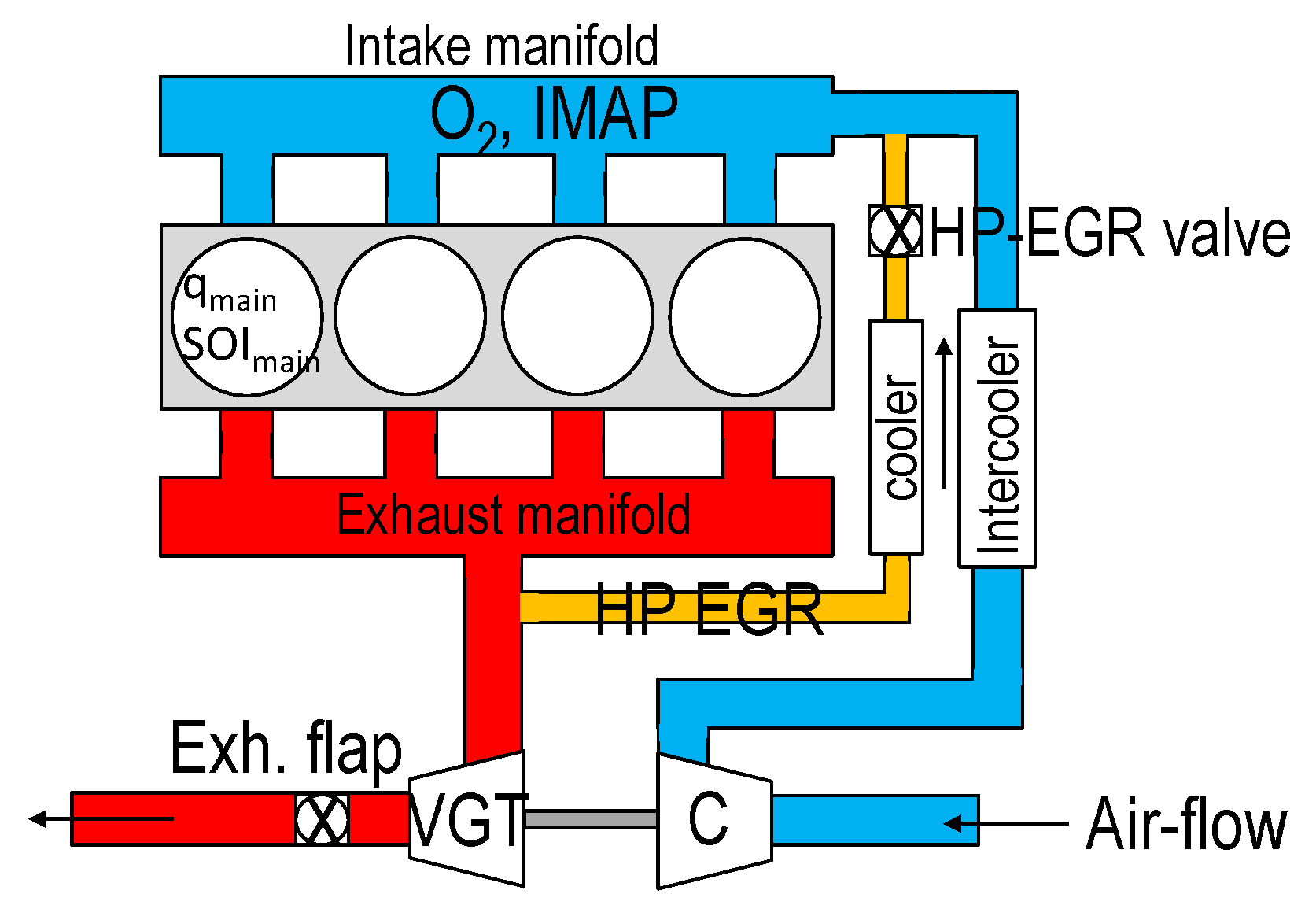
3.1. Air Path Control System

Intake O 2 concentration and IMAP are regulated using a NonLinear Quadratic Regulator (NLQR) that commands the position of the EGR and VGT actuators. The designed control system embeds two Multiple-Input Single-Output (MISO) NARX model networks: one network forecasts the intake O 2 concentration and the other one the IMAP. They are both characterized by two hyperbolic tangent hidden neurons and a one-neuron linear output layer. Five inputs are exploited by the networks: the actual values of the intake O 2 concentration or IMAP, engine speed, engine BMEP, and the position of the HP-EGR and VGT valves.
Recurrent Neural Networks (RNNs) allow using only a single model to identify the I/O pairs’ nonlinear correlations over the entire engine operating range. Furthermore, their low computational time suits real-time ECU implementation. The details of the air path control system can be found in [43]. As a comparison, in the linear case, multiple models are required to cover the entire engine functioning range: examples of linear black-box models can be found in [18,31]. In contrast, an example of a physical model is reported in [44].

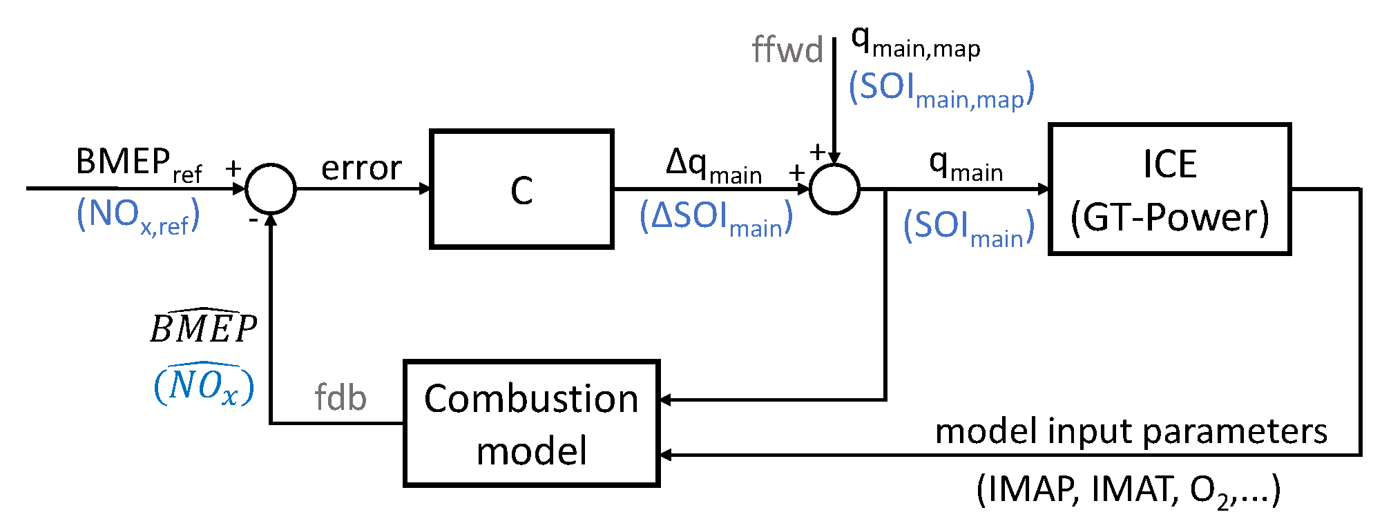
3.2. Combustion Control System

A cycle-to-cycle closed-loop combustion controller manages the engine BMEP and NOx emissions of the diesel engine. The two target variables are regulated by manipulating the injected main pulse fuel quantity q m a i n and its timing ( S O I m a i n ). The closed-loop controller exploits the feedback from a predictive combustion model used as a virtual sensor and calibrated using actual test bench measurements. The model reconstructs a prediction of the in-cylinder pressure trace that is exploited to extract all the combustion metrics of interest. The model can reconstruct the pressure trace with or without physical sensor feedback. The latter case allows for avoiding the use of direct in-cylinder pressure measurement.
The control system includes two separate loops implementing PI and lag regulators, the first one to control the engine load and the other one the NOx. Then, a feedforward term is used to set the nominal values of the two commands by means of specific maps obtained from steady-state tests. The structure allows for independent control of all four cylinders so that eight regulators are used, i.e., two per cylinder. Details of the feedback model can be found in [8] while a deeper description of the control system is provided in [45].

3.3. Coordination Structure

High-level coordination of air and fuel control systems is essential for meeting the conflicting needs between emissions, fuel economy, and driveability. Figure 4 depicts an overview of the developed coordination strategy.
The coordinator is the fulcrum of the combined engine air path and combustion management: it adapts the control targets harmoniously in order to meet the various conflicting performance requirements. The coordinator underwent several development stages. First, preliminary studies were carried out in MATLAB/Simulink using available steady-state and transient experimental tests to ensure the viability of the method. The second stage involved software in the loop testing in co-simulation between Simulink and GT-suite.
In the structure shown in Figure 4, a clear separation between the two control systems is visible. The coordinator receives the target values of engine-out NOx and λ , as well as the engine state variables available from sensors (i.e., engine speed, IMAP, …), and then sets the targets for the air path controller (intake O 2 concentration and IMAP), on the basis of specifically trained neural networks. Therefore, the input targets for the air path control are closely correlated to the desired NOx and λ targets, and, if the air path control achieves the desired O 2 and IMAP targets, the emitted NOx and λ values will align towards the related desired targets. Concerning the combustion controller, its targets are the engine-out NOx and the BMEP, which is decided by the driver or by time-varying profiles in simulations. (It is important to point out that the red arrows in Figure 4 are bidirectional.) As a consequence, the coordinator not only sends the targets to the control systems but, at the same time, receives feedback from them.
It has to be noted that the air path controller is characterized by slow dynamics since it has to achieve the desired O 2 and IMAP targets by acting on the EGR and VGT valve positions, while the combustion controller is able to achieve the desired NOx and BMEP targets in a faster way on a cycle-to-cycle basis by acting on S O I m a i n and q m a i n . Therefore, the coordinator is intended to manage the air path control so that it achieves the desired O 2 and IMAP targets and, indirectly, also the engine-out NOx and λ targets in steady state or slow varying conditions. At the same time, the coordinator manages the combustion control to compensate for the fast transient deviations of NOx and BMEP with respect to the targets on a cycle-to-cycle basis. In other words, the air path controller has to provide the global condition for the engine to run and allow the combustion control system to fulfill the requested torque. In addition, the combustion control compensates for fast variations and offsets in both load and NOx-emitted pollutants.

4. Coordinator Design

The coordinator was designed to exploit machine learning techniques, in particular neural network methodologies, such as having complete control over the air path by means of its target generation. To get this result, two separate neural networks were used, one for the O 2 and one for the IMAP. The first net inputs were the engine speed, engine BMEP, S O I m a i n , rail pressure, desired NOx, and λ to produce an oxygen target. The second one uses injected fuel quantity, O 2 , and desired λ to generate an IMAP target. It can be noted that the inputs for the two networks were selected in order to account for the mutual effects between IMAP and O 2 . Moreover, the variables related to the combustion control (i.e., S O I m a i n , rail pressure, q m a i n ) have been used as inputs, and this allows the obtainment of a more consistent control between the air path and combustion control systems. The network structure for the O 2 reference generator is made of one input layer, eight hidden layers, and one output layer (a typical shallow neural network), while the network for the IMAP target definition features one input layer, three hidden layers, and one output layer. The detailed GT-suite model of the engine was used to generate the separate datasets on which the nets were trained and validated. Model training and validation have been performed using the MATLAB Deep Learning Toolbox.

4.1. Network Training

The GT-suite model of the engine was employed to build the dataset used to train the two networks constituting the reference generator. The dataset included more than 9000 points obtained by simulating a Design Of Experiment (DOE) over the entire engine map in which engine speed, injected fuel quantity, and timing of the main pulse, rail pressure, EGR, and VGT positions were varied.
The whole set of points was divided into three parts: 70% of the points (randomly selected) were used for the training, 15% were used for the validation, and 15% were used for the test (the validation dataset was used to check whether the training was complete, while the test dataset was basically used to verify the general predictive capability of the network). In general, it is a commonly adopted practice to split the dataset into two parts, which include 50–70% of the points for the training and 50–30% for the validation/test. Concerning the selection of the optimal sample size, there is not any general rule. On the basis of the authors’ experience, a dataset of at least 2000 points which includes the variation of all the main engine variables, is sufficient to obtain a neural network-based model with good predictive capability for training, validation, and testing aims.
A range from 1 to 30 hidden layers has been covered in training in order to find the networks that offered the best compromise between accuracy vs. complexity. Furthermore, each hidden layer training was repeated ten times by changing the initial value of the weights after which the best training was selected. The selected network for the O 2 features eight hidden layers and performance indexes of RMSE = 0.245% and R 2 of 0.985. Instead, a network with three hidden layers was sufficient for the IMAP target definition since the RMSE and R 2 values were equal to 0.042 and 0.995 bar, respectively.

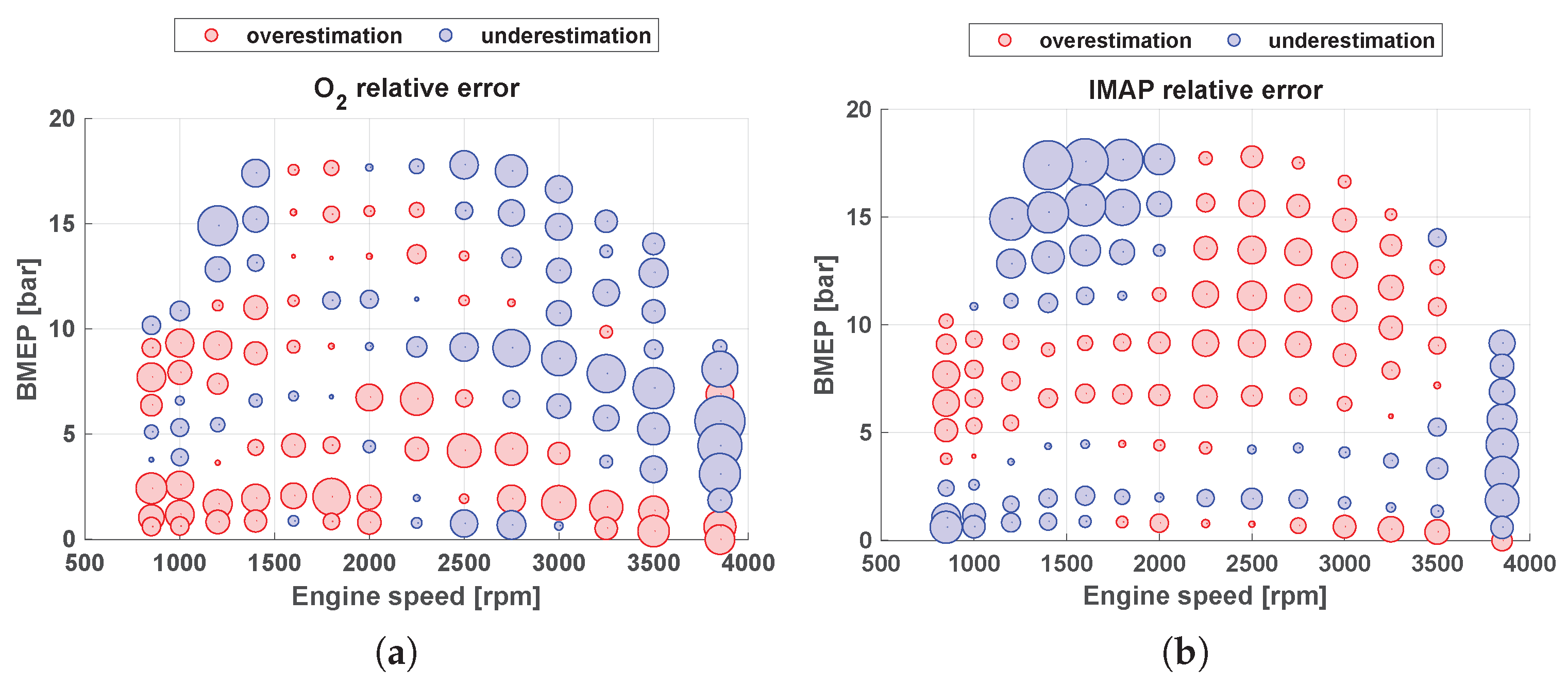
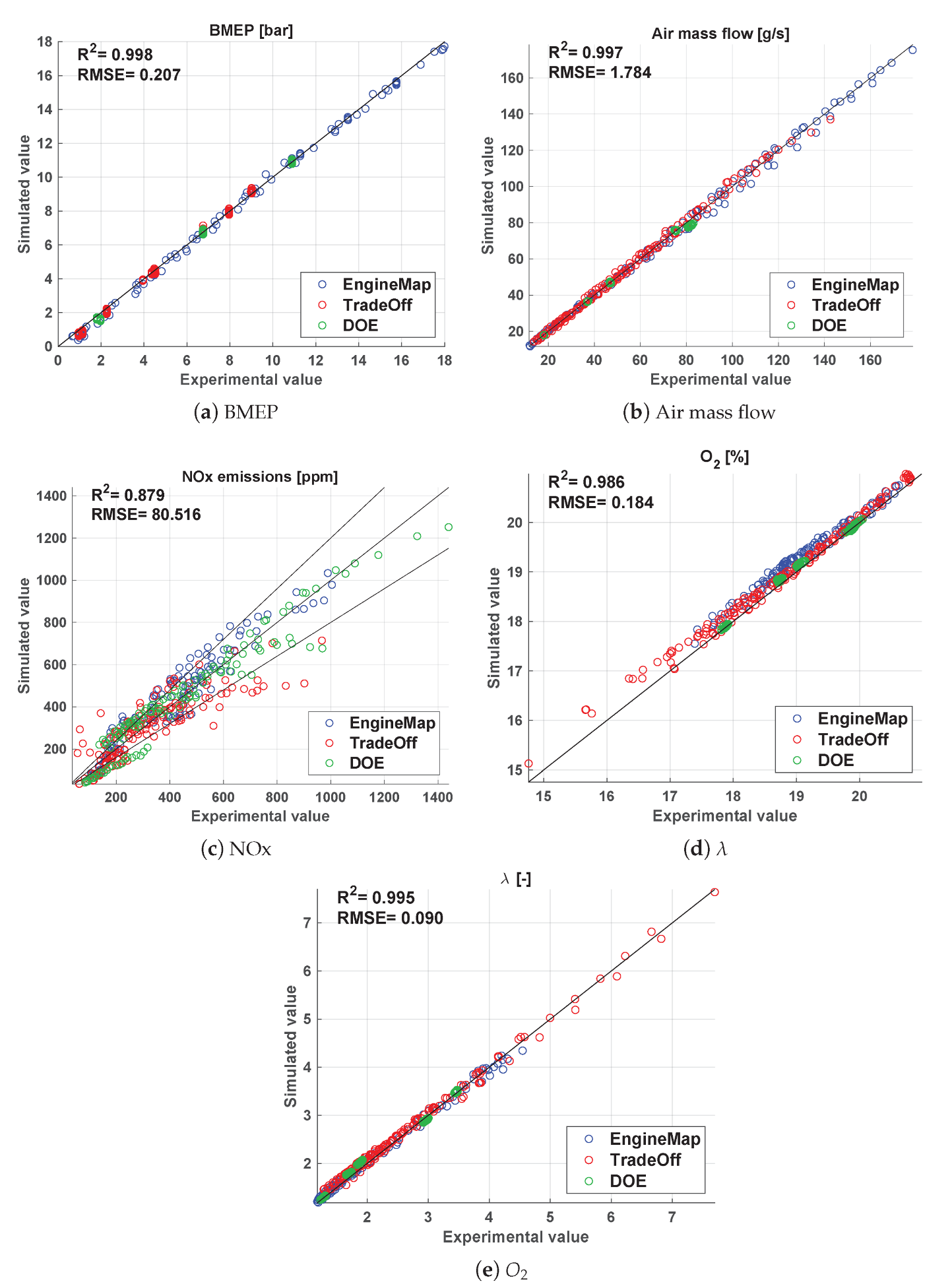
4.2. Steady State Validation

A dataset made of 413 tests simulated in GT-suite that included a full engine map, an intake O 2 concentration tradeoff obtained through sweeps of EGR and VGT valve positions, and a local DOE of S O I m a i n and rail pressure were used to analyze the steady-state behavior of the networks. The O 2 network predicts the GT-suite values with a coefficient of determination of 0.958 and RMSE of 0.195%, as can be seen in Figure 5a. The network returns a maximum relative error of −2.5% and +2% mainly from 2500 rpm to 3750 rpm over the engine map, Figure 6a. The values of RMSE and R 2 (equal to 0.025 and 0.994 bar, respectively, see Figure 5b) also confirm the good performance for the network that predicts the IMAP. The maximum relative error of this network is between −5.5% and +2% over the entire engine map, where the largest errors occur in a speed range between 1250 and 2000 rpm, with a BMEP higher than 10 bar, Figure 6b.

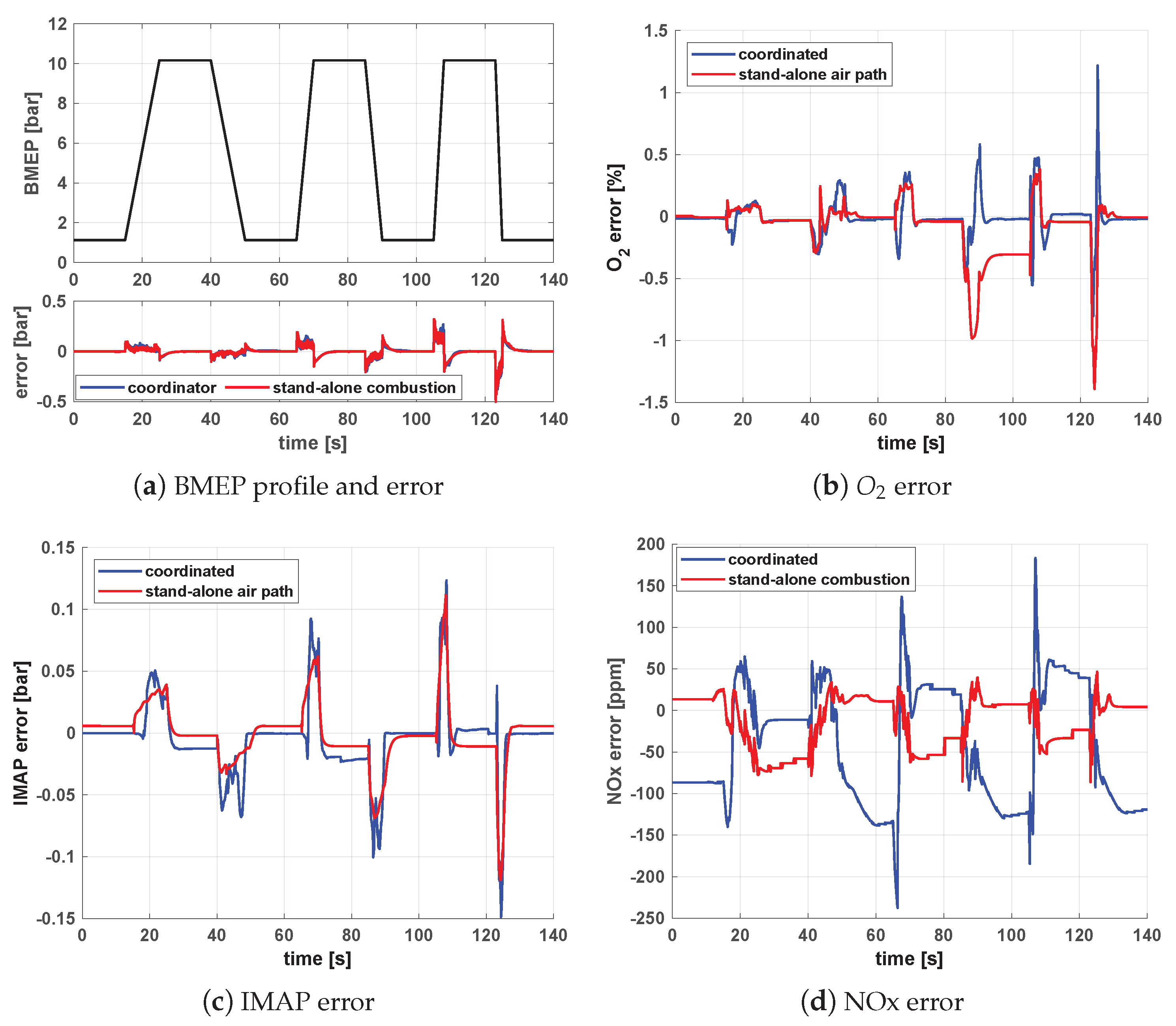
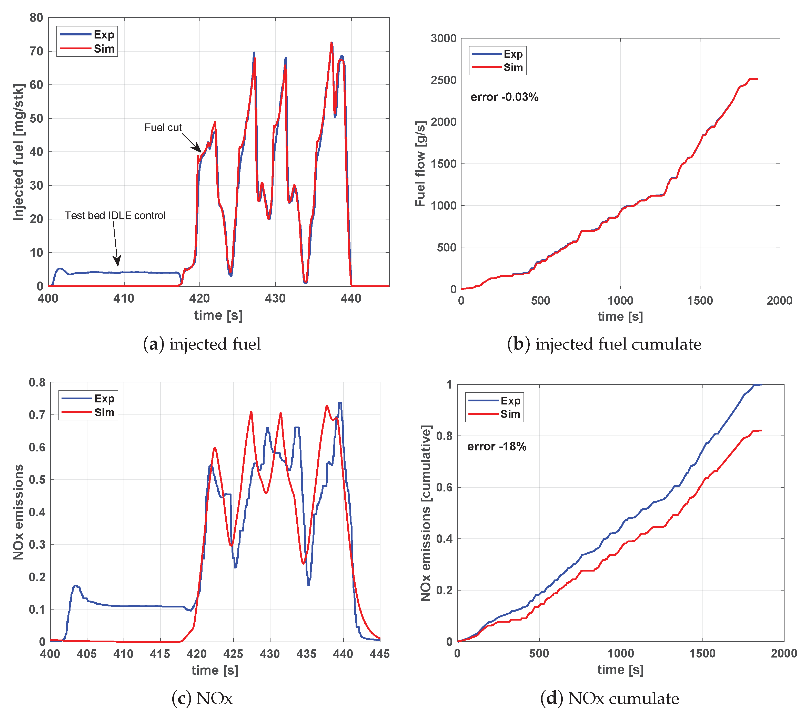
4.3. Transient Validation

Multiple tests have been conducted to verify the network response in transient conditions:
1.
Slow varying load hat ramps at different speeds, used to verify the steady state results.
2.
Hat ramps where speed and load vary together over the whole engine map.
3.
A World Harmonized Transient Cycle (WHTC) test.
In all tests, the trained networks were fed with GT-suite values to compare their prediction of O 2 and IMAP over GT-suite simulated values. For the sake of briefness and clarity, only a portion of the WHTC cycle is presented in this paper. For the description of hat ramp results, refer to [46].
The results of the WHTC test are reported in Figure 7a for the O 2 and in Figure 7b for the IMAP. Both figures show the same section of the WHTC from time t = 990 s to time t = 1045 s. The intake manifold O 2 network, red line in Figure 7a, correctly reproduces the GT-suite trace shown in blue. The behavior is regular, even though undershoots tend to appear due to the GT-suite predicted NOx value. Errors are marginal and contained in a very small range. Figure 7b shows the IMAP network performance (red line) over the GT-suite signal (blue line): overall, the network reproduces the GT-suite trace correctly. However, a significant overestimation is clearly visible in the interval between t = 1020 s and t = 1030 s, as well as for t = 1040 s. These phases correspond to the engine entering idling or fuel cutoff. Due to the very low, or null, value of injected fuel quantity and consequently very high lambda value, the network asks for high boost pressure values. This is a purely mathematical product, unfeasible and without meaning in the real engine, and without any significant impact on the engine controller performance. To deal with these conditions, the whole controller structure is, in fact, disabled when the injected fuel mass is below 5 mg/cycle of total injected fuel mass, and the air path and combustion systems are regulated in open-loop by steady-state maps.

5. Coordination Results

The results of the air path and combustion control coordination MiL tests are presented in this section. First, the coordinated controllers are compared with their unsupervised performance over a load and a speed ramp in Section 5.1. Then, the coordinated controller performances are further analyzed over different ramps and a WHTC in Section 5.2.

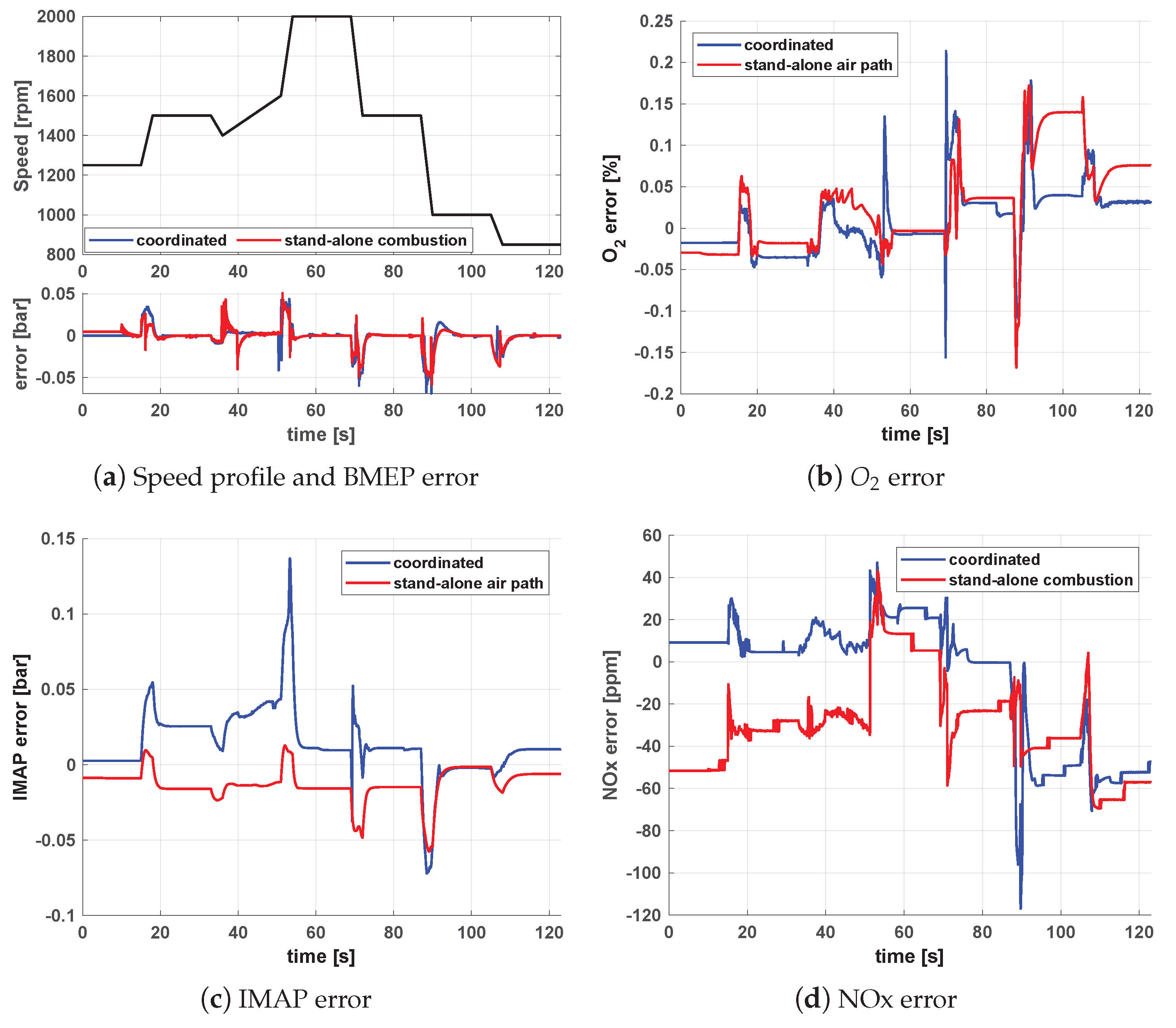
5.1. Comparison with the Uncoordinated Control Systems

Figure 8 and Figure 9 report a comparison between the performance of the coordinated air path and combustion control systems (results indicated with “coordinated” blue lines) and the performance of the uncoordinated control systems (red lines) for a load ramp at 1250 rpm and a speed ramp at BMEP = 8 bar, respectively. In the uncoordinated control case, the air path controller and combustion controller operate independently of each other. In other words, when the stand-alone air path controller is tested, the combustion controller is disabled, and the S O I m a i n and q m a i n are set by steady-state maps. Conversely, when the stand-alone combustion controller is enabled, the air path controller is disabled, and the VGT and EGR valve positions are set by steady-state maps.
Beginning with the load ramp at 1250 rpm, whose profile is reported in the upper portion of Figure 8a, the error over the BMEP remains practically the same in both conditions. Figure 8b shows the O 2 error in blue for the coordinated control structure and in red for the stand-alone air path. The benefits of the coordination start to be noticeable from time t = 80 s. With the introduction of the coordinator, the deviation from the target is reduced in both amplitude and duration. The intake manifold pressure error, Figure 8c, remains practically the same and is limited to small values. With reference to the NOx, Figure 8d, it can be seen that the coordinated control tends to reduce the error generally at higher loads (where the production of NOx is more critical), but leads to a higher error at low load conditions. As will be shown in the next section, the main explanation for this result is due to the fact that the maximum λ value that is given as input to the reference generator is saturated (in order to make the neural networks that define the air-path targets more robust), while the actual λ values are very high (due to the low injected fuel mass). This deviation generates an underestimation of the NOx at lower loads.
The second comparison is over a speed ramp at a constant 8 bar BMEP depicted in black in the upper portion of Figure 9a. From the lower portion of the figure, it is visible that the error over the BMEP again remains practically the same, regardless of the speed variation. Figure 9b shows that the O 2 error is smaller when the coordinated controller is considered (blue line), even though some spikes are visible at t = 52 s and t = 70 s due to the sudden speed changes. The intake manifold pressure error, Figure 9c, shows that the coordinated controller (blue line) leads to worse performance than that of the stand-alone air path controller (red line), but the deviations are still acceptable. With reference to the NOx error, Figure 9d shows that the coordinated control, in general, leads to better performance, apart from the time interval around t = 90 s, in which a steep speed variation occurs. From the previous results, it can be concluded that the adoption of the coordinated controller leads to a better matching of the O 2 targets and of the NOx targets, especially at higher loads where the NOx is more critical.
It should be noted that the main advantage of the proposed coordinated controllers (in comparison with the stand-alone approach) is the possibility of defining a desired NOx target for the engine over the driving mission, which in turn leads to the definition of O 2 and IMAP targets for the air path controller, which are continuously adapted in real-time. At the same time, the combustion controller compensates for fast variations and offsets in both load and NOx emitted pollutants by acting on the start of injection of the main pulse and on the fuel injected quantity on a cycle-to-cycle basis. Conversely, a stand-alone approach generally uses fixed maps to define the air-path and fuel-path targets.
To compare the performance of the Coordinated Control (CoC) approach against the Stand-Alone Control (SAC), Table 2 presents the RMSE index evaluated for the load and speed ramp described above in Figure 8 and Figure 9. Furthermore, for the load ramp (Figure 8), the RMSE index has also been evaluated for BMEP lower and higher than 5 bar. This analysis confirms that the overall performance of the coordinated structure is satisfactory, and the major benefits compared to the stand-alone strategy are retrieved at the higher loads.

5.2. Coordinated Controllers

The main advantage of the proposed coordinated control system is the possibility of defining different input targets for NOx emissions. The two targets simulate different admissible emission levels depending on the engine’s working condition. On the basis of these targets, the coordinator will define suitable references of intake O 2 and IMAP for the air path controller, while, at the same time, the combustion controller adjusts the S O I m a i n and q m a i n variables to compensate for remaining NOx deviations while achieving the requested BMEP. The results reported here show the behavior of the control system when setting two separate NOx targets defined by two distinct maps. In the following figures, the targets are referred to as target 1 and target 2, and the corresponding simulations are indicated through sim 1 and sim 2. The engine load, i.e., BMEP, was imposed by a single time-varying profile. Moreover, the λ set point was also the same for both simulations since a single map was used to define it. The following colors are used in all the figures: green–target 1, cyan–target 2, blue–simulation result with target 1, and magenta–test result with target 2.
The first test is a load ramp at a fixed speed of 850 rpm, Figure 10. Figure 10a shows that the BMEP error is contained in the ±0.2 bar range for both tests with different NOx targets, with only two samples exception. With reference to the IMAP error, Figure 10b shows that it is very small and limited to ±0.1 bar, except for a spike that occurs at t = 110 s for the second test (magenta line). Figure 10c presents the intake O 2 concentration profiles. The O 2 error, as shown in Figure 10d, is in general small, apart from a few time instants (i.e., t = 20 s, t = 90 s, t = 140 s). In these conditions, a sharp target variation occurs, and the control systems feature a small lag. The two targets are very different, but the air path control system closely matches the desired values in both cases. From Figure 10c, it is also possible to see that the reference generator produces an oscillating target in both simulations.
To conclude the analysis over this first ramp, the NOx emissions are shown in Figure 10e. From this figure, it is possible to see that the controller allows the achievement of the two desired targets with an acceptable error, which is in the ±100 ppm range. Larger deviations occur at the beginning and the end of the ramps (i.e., at very low load conditions), over which the average error is of the order of 150 ppm (see Figure 10f). The first test (blue line) is characterized by a greater variability.
The results for a load ramp at 3000 rpm in the high-end torque region are shown in Figure 11. By looking at Figure 11a, it is possible to see that a good matching is achieved between the simulated and the target values of BMEP for both considered cases. The error tends to increase slightly at very low load conditions. The profile obtained following the second NOx target, i.e., the magenta line, also shows some oscillations at the higher torque levels. Figure 11b presents the target and simulated λ values. The targets are equal for the two considered cases (sim1 and sim2) because the λ reference value is stored in a single SS map as a function of engine speed and BMEP. a large deviation is evident in Figure 11b between the actual and target values of λ at low-load conditions (BMEP < 2 bar). The reason for this deviation can be explained by considering that the highest λ value stored in the map is 3.4 (in order to make the network performance more stable). In the low load sections, with the intervention of the fuel control system that reduces the injected fuel mass, the λ value increases to a level that is close to 5. However, the lambda deviation at lower loads does not have a significant impact on the controller performance. Instead, the λ target is closely matched at a high load, regardless of whether the transient is fast or not.
Moving to the intake O 2 concentration, Figure 11c shows that the control system closely matches the two targets. However, it can be noted that the O 2 targets defined by the reference generator display some gaps during the transients. This is remarkable, especially for case 1 (green line). This behavior may be ascribed to the fact that a too-low NOx target is requested when the load is already increasing and, as a consequence, the coordinator asks for a low oxygen concentration. This behavior could be improved by optimizing the definition of the NOx target. Concluding, Figure 11d shows the intake O 2 concentration error. The mismatch at the lower load is approximately on the order of 0.1%. The other deviations correspond to the transients and increase with their sharpness. However, the mismatch lasts a couple of time samples. Concerning the NOx, Figure 11e shows the two separate targets and the corresponding simulated trends derived from the controller. The S O I m a i n control loop limits the mismatch to around ±100 ppm, Figure 11f. Figure 11g,h show, respectively, the target/simulated IMAP values for the two considered cases, as well as the IMAP error. These results are useful to understand the λ error occurring at low load conditions, which was shown in Figure 11b. In fact, higher values of IMAP with respect to the targets occur at low load conditions (of the order of +0.3 bar), which in turn cause the lambda to reach values around five for the same operating conditions. Over the rest of the profile, the error is very close to zero.
The third presented test is a portion of a WHTC that has been performed two times, providing two different NOx targets. Figure 12a shows the NOx errors on this portion of the cycle: they are generally contained between ±150 ppm for both calibrations. More significant deviations are only limited to a very small-time duration, in correspondence to the sharpest load changes, as expected. Overall, this small error over the NOx means that the oxygen targets are closely followed. The cumulative NOx emissions over the entire WHTC deviate in the ± 5 % range, as will be seen later. As expected from the NOx error results, both intake O 2 concentration targets derived from the two NOx calibrations are correctly followed (Figure 12b). Only during the most aggressive transients, in the attempt to follow the target, are undershoots present, with the error reaching 1.5% at time t = 540 s. However, this mismatch is limited to the first samples of the transient maneuver.
Figure 12c shows the BMEP target (upper chart) and the error for the two simulations (lower chart) for this section of the WHTC. The maximum error is 0.98 bar for sim 1 occurring at time t = 543 s. Furthermore, it is visible that the error is higher when the BMEP variation is more severe, from time t = 540 s to time t = 555 s. The average error for the BMEP is around 0.45 bar. By looking at Figure 12d, where the IMAP is shown, it is visible that the two targets imposed by the reference generator are very sharp as a reflection of the BMEP profile of this WHTC portion. The results of the two simulations are very similar to each other. Nonetheless, the second calibration shows a larger error due to the sharper target variations than the first simulation. In this case, the error reaches 0.45 bar.
Figure 12e presents the λ value. The targets are equal in both “sim1” and “sim2” cases because the λ reference value is stored in a single steady state map. A large deviation is immediately evident between the target and the two simulations. This happens because the highest λ value stored in the map is four. In the low load sections, with the intervention of the fuel control system that reduces the injected fuel mass, λ reaches much higher values than four. However, in these conditions, this mismatch is not a problem since smoke production is not a primary concern. On the contrary, the λ target is closely matched at higher loads, regardless of whether the transient is fast or not.
Table 3 reports the NOx cumulative index for the two ramps and the WHTC that have been previously discussed. For the first load ramp at 850 rpm, the difference in the cumulative NOx emissions concerning the first target is 5.05% while only 1.1% for the second simulation. Instead, the second load ramp at 3000 rpm shows a cumulative deviation with respect to the first NOx target of 7.83% and of 2.74% for the second target. Deviations of 5.8% and 4.75% occur for simulations 1 and 2, respectively, over the WHTC. Through Table 3 it is visible how the coordinated structure allows following different NOx targets with an average error around 5%.
It should be noted that the aim of the coordinator networks is to predict the physical dependence between the quantities that have been used as targets for the controllers (i.e., O 2 and IMAP) and the most influential engine variables (i.e., engine speed, BMEP, S O I m a i n , rail pressure, NOx and λ for the O 2 network; injected fuel quantity, O 2 and λ for the IMAP network). Therefore, a wide set of steady-state operating conditions was designed to perform the training. It was verified that this approach was sufficient to obtain a good prediction of O 2 and IMAP not only at steady state operation but also in transient operation (as can be seen in Figure 7, which reports the network performance over a portion of the WHTC cycle), where the actual engine operating conditions deviate from the baseline ones. On the contrary, if the engine hardware is changed, the networks need to be recalibrated.
A significant aspect to take into account, instead, is that the reference O 2 and IMAP targets, which are selected by the coordinator, are strongly influenced by the NOx target request. An example can be seen in Figure 11. If a too low NOx target is requested during an acceleration ramp (e.g., target 1 in Figure 11e), a very low O 2 reference target may be generated, as can be seen in Figure 11c, and vice-versa for the target 2 case. Therefore, it is very important to define an optimal NOx target that takes into account transient engine effects, such as the turbo-lag, so that the O 2 and IMAP targets which are generated by the coordinator are achievable by the engine.

6. Conclusions

This work aimed at developing coordinated air path and combustion controllers for a diesel engine to guarantee its correct functioning while fulfilling a given NOx emission target. A virtual engine model was used to reproduce the actual ICE while designing and assessing the control systems to fulfill this objective. The control systems developed in this work include an NLQR, PI, and lag compensator. The air path controller acts on the EGR and VGT valves to achieve the desired intake O 2 and boost pressure targets, while the combustion controller acts on the injected fuel mass and starts injection of the main pulse to achieve the desired NOx and BMEP targets on a cycle-to-cycle basis. A coordinator, based on neural networks, was developed in order to identify the optimal set point for the air path controller. In particular, the air path O 2 target is generated considering a desired NOx set point and the engine and combustion control states through engine speed and load, rail pressure, and S O I m a i n . Instead, the IMAP target is generated given a desired λ , intake O 2 , and injected fuel mass. The same load and NOx targets used for the air path targets generation are also sent to the combustion control system as input. The controllers were first tested independently, and then assessed by enabling the coordinator. It was shown that the coordinated system leads to advantages compared with the stand-alone controllers.
During the analysis of the reference generator validation, it emerged that some inputs had to be filtered out to avoid micro oscillations or, in case of speed/load transients, to avoid spikes due to their sharp derivatives. Furthermore, when the engine enters idling and cutoff, the coordinator and the control systems have to be switched off. From previous work, the lower limit of injected fuel below 5 mg/cycle is a suitable threshold for this scope. In these conditions, it is better to rely on steady-state maps to avoid control system instability that could lead to permanent engine damage or, worse, endanger the driver’s safety.
Simulations showed encouraging results. The structure efficiently allowed following different NOx targets, achieving an average error of 0.3 bar for the BMEP and 100÷150 ppm for the NOx. λ regulation suffered the IMAP deviations from the target. Nonetheless, the control was very accurate at high load, where the impact of NOx emissions was more significant.
In conclusion, the simulations showed the approach viability and satisfactory performance. Future work will assess the feasibility of the approach with a NOx target that changes dynamically over the transient and by implementing the logic on a rapid prototyping device.

Author Contributions

The authors contributed equally to the preparation of the paper. Conceptualization, L.V., R.F. and S.A.M.; methodology, L.V., R.F. and S.A.M.; software, L.V.; validation, L.V.; formal analysis, L.V., R.F. and S.A.M.; data curation, L.V.; writing—original draft preparation, L.V.; writing—review and editing, L.V., R.F. and S.A.M.; supervision, R.F. and S.A.M. All authors have read and agreed to the published version of the manuscript.

Funding

This research received no external funding.

Institutional Review Board Statement

Not applicable.

Informed Consent Statement

Not applicable.

Data Availability Statement

No new data were created or analyzed in this study. Data sharing is not applicable to this article.

Conflicts of Interest

The authors declare no conflict of interest.

Abbreviations

The following abbreviations are used in this manuscript:
λ Relative air-to-fuel ratio
ARXAutoRegressive model with eXogenous input
BMEPBrake Mean Effective Pressure
C O 2 Carbon Dioxide
DOEDesign Of Experiment
ECUElectronic Control Unit
EGRExhaust Gas Recirculation
HPHigh-Pressure
ICEInternal Combustion Engine
HRRHeat Release Rate
IMAPIntake MAnifold Pressure
IMEPIndicated Mean Effective Pressure
MAFAir Mass Flow rate
MFB5050% of Burned Mass Fraction
MiLModel-in-the-Loop
MIMOMultiple Input Multiple Output
MISOMultiple Input Single Output
MPCModel Predictive Control
NARXNonlinear AutoRegressive model with eXogenous input
NLQRNonLinear Quadratic Regulator
NOxOxides of Nitrogen
O 2 Oxygen
PIDProportional–Integral–Derivative controller
PMParticulate Matter
qFuel injection quantity
SiLSoftware-in-the-Loop
SOIStart Of Injection
SSSteady State
VGTVariable Geometry Turbocharger
WHTCWorld Harmonized Transient Cycle
subscript mainMain injection pulse

Appendix A

This appendix contains the results of the GT-suite engine model validation, both in steady state and transient. Figure A1 shows the steady state case where the validation is reported through the correlation between experimental and simulated values and the metrics of root-mean-square error and coefficient of determination. The figures present only the main variable of interest for the work, i.e., BMEP, air mass flow rate, NOx emissions, O 2 concentration, and λ .
The transient case is shown in Figure A2 by the comparison of experimental and simulated injected fuel and NOx signals, in time domain, over a portion of the WHTC cycle, both as instantaneous and cumulative values. The main difference is given by the idle speed condition that, in simulation, shows a complete cut of the injected fuel.
Figure A1. GT-suite engine model validation: steady-state.
Energies 16 00907 g0a1
Figure A2. GT-suite engine model validation: transient.
Energies 16 00907 g0a2

References

  1. EIA. International Energy Outlook 2019; United States Energy Information Administration: Washington, DC, USA, 2019. [Google Scholar]
  2. Kalghatgi, G. Is it really the end of internal combustion engines and petroleum in transport? Appl. Energy 2018, 225, 965–974. [Google Scholar] [CrossRef]
  3. Ritchie, H.; Roser, M.; Rosado, P. CO2 and Greenhouse Gas Emissions. Our World in Data. 2020. Available online: https://ourworldindata.org/co2-and-other-greenhouse-gas-emissions (accessed on 9 January 2023).
  4. Baratta, M.; Finesso, R.; Misul, D.; Spessa, E. Comparison between Internal and External EGR Performance on a Heavy Duty Diesel Engine by Means of a Refined 1D Fluid-Dynamic Engine Model. SAE Int. J. Engines 2015, 8, 1977–1992. [Google Scholar] [CrossRef]
  5. Ferrari, A.; Jin, Z.; Vento, O.; Zhang, T. An injected quantity estimation technique based on time–frequency analysis. Control Eng. Pract. 2021, 116, 104910. [Google Scholar] [CrossRef]
  6. d’Ambrosio, S.; Ferrari, A.; Mancarella, A.; Mancò, S.; Mittica, A. Comparison of the Emissions, Noise, and Fuel Consumption Comparison of Direct and Indirect Piezoelectric and Solenoid Injectors in a Low-Compression-Ratio Diesel Engine. Energies 2019, 12, 4023. [Google Scholar] [CrossRef] [Green Version]
  7. Cococcetta, F.; Finesso, R.; Hardy, G.; Marello, O.; Spessa, E. Implementation and Assessment of a Model-Based Controller of Torque and Nitrogen Oxide Emissions in an 11 L Heavy-Duty Diesel Engine. Energies 2019, 12, 4704. [Google Scholar] [CrossRef] [Green Version]
  8. Finesso, R.; Marello, O.; Spessa, E.; Yang, Y.; Hardy, G. Model-Based Control of BMEP and NOx Emissions in a Euro VI 3.0L Diesel Engine. SAE Int. J. Engines 2017, 10, 2288–2304. [Google Scholar] [CrossRef]
  9. d’Ambrosio, S.; Gaia, F.; Iemmolo, D.; Mancarella, A.; Salamone, N.; Vitolo, R.; Hardy, G. Performance and Emission Comparison between a Conventional Euro VI Diesel Engine and an Optimized PCCI Version and Effect of EGR Cooler Fouling on PCCI Combustion. In Proceedings of the WCX World Congress Experience, Detroit, MI, USA, 10–12 April 2018; SAE International: Warrendale, PA, USA, 2018. [Google Scholar] [CrossRef]
  10. d’Ambrosio, S.; Mancarella, A.; Manelli, A. Utilization of Hydrotreated Vegetable Oil (HVO) in a Euro 6 Dual-Loop EGR Diesel Engine: Behavior as a Drop-In Fuel and Potentialities along Calibration Parameter Sweeps. Energies 2022, 15, 7202. [Google Scholar] [CrossRef]
  11. Bunce, M.; Blaxill, H. Sub-200 g/kWh BSFC on a Light Duty Gasoline Engine. In Proceedings of the SAE 2016 World Congress and Exhibition, Detroit, MI, USA, 12–14 April 2016; SAE International: Warrendale, PA, USA, 2016. [Google Scholar] [CrossRef]
  12. Kargul, J.; Stuhldreher, M.; Barba, D.; Schenk, C.; Bohac, S.; McDonald, J.; Dekraker, P.; Alden, J. Benchmarking a 2018 Toyota Camry 2.5-Liter Atkinson Cycle Engine with Cooled-EGR. SAE Int. J. Adv. Curr. Pract. Mobil. 2019, 1, 601–638. [Google Scholar] [CrossRef] [PubMed]
  13. Bejan, A. Thermodynamics today. Energy 2018, 160, 1208–1219. [Google Scholar] [CrossRef]
  14. Ventura, L. Development and Assessment of Model-Based and Sensor-Based Algorithms for Combustion and Emission Control in Diesel Engines. Ph.D. Thesis, Politecnico di Torino, Torino, Italy, 2022. [Google Scholar]
  15. Xie, H.; Song, K.; Yang, S.; Tatsumi, J.; Zheng, Q.; Zhang, H.; Gao, Z. On Decoupling Control of the VGT-EGR System in Diesel Engines: A New Framework. IEEE Trans. Control Syst. Technol. 2016, 24, 1788–1796. [Google Scholar] [CrossRef]
  16. Isermann, R. Engine Modeling and Control: Modeling and Electronic Management of Internal Combustion Engines; Springer: Berlin/Heidelberg, Germany, 2014. [Google Scholar]
  17. Malan, S.A.; Ventura, L. Air-Path Control for a Prototype PCCI Diesel Engine. In Proceedings of the 2018 26th Mediterranean Conference on Control and Automation (MED), Zadar, Croatia, 19–22 June 2018; pp. 843–848. [Google Scholar] [CrossRef]
  18. Ventura, L.; Finesso, R.; Malan, S.A.; d’Ambrosio, S.; Manelli, A. Model-based design of closed loop controllers of the air-path in a heavy duty diesel engine. AIP Conf. Proc. 2019, 2191, 020152. [Google Scholar] [CrossRef]
  19. Das, H.B.; Dhinagar, S.J. Airpath Modelling and Control for a Turbocharged Diesel Engine. In Proceedings of the SAE 2008 World Congress & Exhibition, Detroit, MI, USA, 14–17 April 2008; SAE International: Warrendale, PA, USA, 2016. [Google Scholar] [CrossRef]
  20. Alfieri, E.; Amstutz, A.; Guzzella, L. Gain-scheduled model-based feedback control of the air/fuel ratio in diesel engines. Control Eng. Pract. 2009, 17, 1417–1425. [Google Scholar] [CrossRef]
  21. Deng, C.; Colin, G.; Chamaillard, Y.; Gruel, D.N. Sequential robust control design methodology application to the MIMO air path of a diesel engine. In Proceedings of the IECON 2012–38th Annual Conference on IEEE Industrial Electronics Society, Montreal, QC, Canada, 25–28 October 2012; pp. 2138–2143. [Google Scholar] [CrossRef]
  22. Liu, L.; Wei, X.; Liu, X. Low order H∞ controller design for the air path system of diesel engines. In Proceedings of the 2009 4th IEEE Conference on Industrial Electronics and Applications, Xian, China, 25–27 May 2009; pp. 3470–3475. [Google Scholar] [CrossRef]
  23. Ahmed, F.S.; Laghrouche, S.; Bagdouri, M.E. Second-order sliding mode based output-feedback control of an engine air path actuator in presence of uncertainties. In Proceedings of the 2010 Conference on Control and Fault-Tolerant Systems (SysTol), Nice, France, 6–8 October 2010; pp. 50–56. [Google Scholar] [CrossRef]
  24. Irdmousa, B.K.; Rizvi, S.Z.; Veini, J.M.; Nabert, J.D.; Shahbakhti, M. Data-driven Modeling and Predictive Control of Combustion Phasing for RCCI Engines. In Proceedings of the 2019 American Control Conference (ACC), Philadelphia, PA, USA, 10–12 July 2019; pp. 1617–1622. [Google Scholar] [CrossRef]
  25. Norouzi, A.; Heidarifar, H.; Shahbakhti, M.; Koch, C.R.; Borhan, H. Model Predictive Control of Internal Combustion Engines: A Review and Future Directions. Energies 2021, 14, 6251. [Google Scholar] [CrossRef]
  26. Mittelmann, H. Decision Tree for Optimization Software. 2021. Available online: http://plato.asu.edu/guide.html (accessed on 9 January 2023).
  27. Yin, L.; Turesson, G.; Tunestål, P.; Johansson, R. Model Predictive Control of an Advanced Multiple Cylinder Engine With Partially Premixed Combustion Concept. IEEE/ASME Trans. Mechatron. 2020, 25, 804–814. [Google Scholar] [CrossRef]
  28. Abidi, I.; Bosche, J.; El Hajjaji, A.; Aitouche, A. Control of a turbocharged diesel engine with EGR system using Takagi-Sugeno’s approach. In Proceedings of the 2012 20th Mediterranean Conference on Control Automation (MED), Barcelona, Spain, 3–6 July 2012; pp. 960–965. [Google Scholar] [CrossRef]
  29. Kim, S.; Jin, H.; Choi, S. Pressure and flow based control of a turbocharged diesel engine air-path system equipped with dual-loop EGR and VGT. In Proceedings of the 2014 American Control Conference, Portland, OR, USA, 4–6 June 2014; pp. 1493–1498. [Google Scholar] [CrossRef]
  30. Ljung, L. System Identification: Theory for the User; Pearson Education: London, UK, 1998. [Google Scholar]
  31. Malan, S.; Ventura, L. A Systematic Procedure for Engine Air-Path Identification. Int. J. Mech. Control 2020, 21, 127–138. [Google Scholar]
  32. Ortner, P.; del Re, L. Predictive Control of a Diesel Engine Air Path. IEEE Trans. Control Syst. Technol. 2007, 15, 449–456. [Google Scholar] [CrossRef]
  33. Willems, F.; Doosje, E.; Engels, F.; Seykens, X. Cylinder Pressure-Based Control in Heavy-Duty EGR Diesel Engines Using a Virtual Heat Release and Emission Sensor. In Proceedings of the SAE 2010 World Congress & Exhibition, Detroit, MI, USA, 12–15 April 2010; SAE International: Warrendale, PA, USA, 2010. [Google Scholar] [CrossRef] [Green Version]
  34. Yan, F.; Wang, J. Air- and fuel-path coordinated control for advanced combustion mode transitions in Diesel engines. In Proceedings of the 2012 American Control Conference (ACC), Montreal, QC, Canada, 27–29 June 2012; pp. 2890–2895. [Google Scholar] [CrossRef]
  35. Yoon, M.; Lee, K.; Sunwoo, M. A method for combustion phasing control using cylinder pressure measurement in a CRDI diesel engine. Mechatronics 2007, 17, 469–479. [Google Scholar] [CrossRef]
  36. Landsmann, G.; Beasley, M.; Cornwell, R.; Fussey, P.; King, R.; Noble, A.; Salamon, T.; Truscott, A. Reducing Diesel Emissions Dispersion by Coordinated Combustion Feedback Control. In Proceedings of the SAE 2006 World Congress & Exhibition, Detroit, MI, USA, 3–6 April 2006; SAE International: Warrendale, PA, USA, 2006. [Google Scholar] [CrossRef]
  37. Carlucci, A.; Laforgia, D.; Motz, S.; Saracino, R.; Wenzel, S. Advanced closed loop combustion control of a LTC diesel engine based on in-cylinder pressure signals. Energy Convers. Manag. 2014, 77, 193–207. [Google Scholar] [CrossRef]
  38. Luo, X.; Wang, S.; de Jager, B.; Willems, F. Cylinder Pressure-based Combustion Control with Multi-pulse Fuel Injection. IFAC-PapersOnLine 2015, 48, 181–186. [Google Scholar] [CrossRef]
  39. Albin, T.; Ritter, D.; Zweigel, R.; Abel, D. Hybrid multi-objective MPC for fuel-efficient PCCI engine control. In Proceedings of the 2015 European Control Conference (ECC), Linz, Austria, 15–17 July 2015; pp. 2583–2588. [Google Scholar] [CrossRef]
  40. Shin, B.; Chi, Y.; Kim, M.; Dickinson, P.; Pekar, J.; Ko, M. Model Predictive Control of an Air Path System for Multi-Mode Operation in a Diesel Engine. In Proceedings of the WCX SAE World Congress Experience, Detroit, MI, USA, 5–7 April 2020; SAE International: Warrendale, PA, USA, 2020. [Google Scholar] [CrossRef]
  41. Ventura, L.; Malan, S. Intake O2 Concentration Estimation in a Turbocharged Diesel Engine through NOE. In Proceedings of the Conference on Sustainable Mobility, Catania, Italy, 4–7 October 2020; SAE International: Warrendale, PA, USA, 2020. [Google Scholar] [CrossRef]
  42. d’Ambrosio, S.; Finesso, R.; Hardy, G.; Manelli, A.; Mancarella, A.; Marello, O.; Mittica, A. Model-Based Control of Torque and Nitrogen Oxide Emissions in a Euro VI 3.0 L Diesel Engine through Rapid Prototyping. Energies 2021, 14, 1107. [Google Scholar] [CrossRef]
  43. Ventura, L.; Malan, S.A. NLQR Control of High Pressure EGR in Diesel Engine. In Proceedings of the 2020 20th International Conference on Control, Automation and Systems (ICCAS), Busan, Republic of Korea, 13–16 October 2020; pp. 721–726. [Google Scholar] [CrossRef]
  44. Eriksson, L.; Nielsen, L. Modeling and Control of Engines and Drivelines; Automotive Series; Wiley: Hoboken, NJ, USA, 2014. [Google Scholar]
  45. Malan, S.A.; Ventura, L.; Manelli, A. Cycle to cycle closed-loop combustion control through virtual sensor in a diesel engine. In Proceedings of the 2021 29th Mediterranean Conference on Control and Automation (MED), Puglia, Italy, 22–25 June 2021; pp. 1179–1184. [Google Scholar] [CrossRef]
  46. Ventura, L.; Malan, S.A. Air path and combustion controls coordination in diesel engine. In Proceedings of the 2022 22nd International Conference on Control, Automation and Systems (ICCAS), Busan, Republic of Korea, 27 November–1 December 2022; pp. 354–359. [Google Scholar]
Figure 1. Decoupled PID air path control.
Energies 16 00907 g001
Figure 2. Fuel path control of BMEP and NOx through the main injection quantity ( q m a i n ) and timing ( S O I m a i n ).
Energies 16 00907 g002
Figure 3. Engine scheme.
Energies 16 00907 g003
Figure 4. Coordinator Structure.
Energies 16 00907 g004
Figure 5. Reference generator steady state validation. Correlation: (a) O 2 ; (b) IMAP.
Energies 16 00907 g005
Figure 6. Reference generator steady state validation. Relative error map: (a) O 2 ; (b) IMAP.
Energies 16 00907 g006
Figure 7. Reference generator validation over a portion of the WHTC profile: (a) O 2 ; (b) IMAP.
Energies 16 00907 g007
Figure 8. Comparison of the coordinated structure (blue line) with the stand-alone air path and combustion controllers (red line) over a load ramp at 1250 rpm.
Energies 16 00907 g008
Figure 9. Comparison of the coordinated structure (blue line) with the stand-alone air path and combustion controllers (red line) over a speed ramp at 8 bar BMEP.
Energies 16 00907 g009
Figure 10. Load ramp at 850 rpm simulated using two different NOx targets.
Energies 16 00907 g010
Figure 11. Load ramp at 3000 rpm simulated using two different NOx targets.
Energies 16 00907 g011
Figure 12. WHTC portion performed with two different NOx targets.
Energies 16 00907 g012
Table 1. Engine Main Specifications.
Engine typeHeavy-duty Euro VI diesel engine
Number of cylinders4
Displacement2998 cm 3
Bore × stroke95.8 × 104 mm
Rod length160 mm
Compression ratio17.5:1
Valves per cylinder4
TurbochargerVGT type
Fuel injection systemHigh Pressure Common Rail
Table 2. RMSE index for ramps in Figure 8 and Figure 9.
ControlSACCoCSACCoCSACCoCSACCoC
Ramp Figure 8BMEP O 2 IMAPNOx
RMSE0.380.0330.7250.2370.0370.04883.5482.58
BMEP > 5 bar0.1280.0360.1950.2390.0350.06671.2240.85
BMEP < 5 bar0.5060.030.9730.2360.040.02495.8106.22
Ramp Figure 9BMEP O 2 IMAPNOx
RMSE0.1320.0110.110.060.0220.077101.3331.27
Table 3. Cumulative NOx index of simulations exploiting the coordinated control architecture.
sim 1sim 2
Load ramp
at 850 rpm
target5.97diff. perc.
5.05%
target6.16diff. perc.
1.1%
sim6.27sim6.23
Load ramp
at 3000 rpm
target5.25diff. perc.
7.83%
target6.32diff. perc.
2.74%
sim5.66sim6.5
WHTCtarget52.5diff. perc.
5.8%
target53.84diff. perc.
4.75%
sim55.5sim55.71
Disclaimer/Publisher’s Note: The statements, opinions and data contained in all publications are solely those of the individual author(s) and contributor(s) and not of MDPI and/or the editor(s). MDPI and/or the editor(s) disclaim responsibility for any injury to people or property resulting from any ideas, methods, instructions or products referred to in the content.

