
H-Shaped Slot Antenna with Harmonic Tuning Function and Integrated Power Amplifier

1
Electrical and Mechanical Engineering Department, Nagoya Institute of Technology, Nagoya 466-8555, Japan
2
Center for Integrated Research of Future Electronics Division, Institute of Materials and Systems for Sustainability, Nagoya University, Nagoya 464-8601, Japan
*
Author to whom correspondence should be addressed.
Energies 2023, 16(5), 2128; https://0-doi-org.brum.beds.ac.uk/10.3390/en16052128
Submission received: 20 December 2022
/
Revised: 4 February 2023
/
Accepted: 12 February 2023
/
Published: 22 February 2023
(This article belongs to the Special Issue Current Research and Future Development on Wireless Power Transfer Technology)
Abstract
:This study proposes a patch antenna with an H-shaped slot with direct matching and harmonic tuning (rejection) functions for microwave power transfer. This antenna enables an integrated active antenna in which the power amplifier and antenna are directly connected without using a matching circuit for the fundamental frequency and harmonic rejection filter to improve the efficiency of the amplifier. The integrated design also reduces the total size of the amplifier and antenna, allowing for a higher-density array antenna. Characteristic mode analysis was performed to explain the working principle of the harmonic rejection function. The designed antenna at 5.8 GHz was fabricated to study its harmonic tuning function. The magnitude of the reflection coefficient of the proposed antenna was at a fundamental frequency of −40.4 dB for an amplification device with an optimum load impedance of 100 Ohm. At the second harmonic frequency, the magnitude and phase of the reflection coefficient at the second harmonic frequency were −0.79 dB and −177.6°, respectively; at the third harmonic frequency, they were −0.92 dB and −179.5°, respectively. Finally, the designed antenna was integrated into an amplifier circuit to verify that it achieved similar drain efficiency as when using the impedance tuner. It was confirmed that the harmonic rejection function of the proposed antenna increases the drain efficiency of the integrated power amplifier by 5.5%. The measurements revealed that this antenna is suitable for use in microwave power transfer because of its fundamental matching and harmonic-processing capabilities.
1. Introduction
In recent years, microwave power transfer technology has attracted increasing attention. This technology transmits power over long distances and is used for solar power generation in space and power transfer to moving objects, such as drones and airships [1]. At the transmitter side of the microwave power transfer system, it is crucial to reduce the switching losses of power amplifiers to enhance efficiency. Harmonic tuning filters, such as class-F load circuits, are commonly used for this purpose [2,3]. There are two types of class-F load circuits: concentrated constant circuits and distributed circuits. Distributed constant circuits use open or short stubs [4,5], whereas concentrated constant circuits use capacitors and inductors [6]. However, both configurations increase the circuit size, which is a considerable problem when it consists of an active planar array antenna because the element spacing is limited by the size of the integrated amplifier.
Conventional amplifiers and antennas are designed with an input/output impedance of 50 Ω and are connected using an interconnect. This method is effective for low-frequency systems; however, at high frequencies, losses occur at the interconnect. To solve this problem, active antennas consisting of a power amplifier element, an F-class load circuit, and a power transmission antenna on the same substrate are widely adopted [7,8]. Accordingly, the antenna and amplifier are designed as a single unit, eliminating the requirement for an interconnect, and reducing system cost and loss. Thus, the integrated design of a power amplifier and antenna is practical. In this case, the antenna impedance is designed to be the optimal load impedance of the power amplifier. The antenna is directly connected to the power amplifier without using a matching circuit or interconnect cable.
A harmonic rejection function in an antenna is a vital technology consisting of an active antenna. Numerous harmonic rejection structures have been proposed for suppressing harmonic radiation. Common examples include defected ground structures (DGSs) [9,10,11] and electric bandgaps (EBGs) [8,12]. However, these methods change the structure of the ground plate of the feed line and combine it with an antenna element, resulting in a larger size. Several harmonic-processing patch antennas with different patch-element geometries have been proposed [13,14,15]. Both antenna miniaturization and harmonic processing have been achieved. However, the magnitudes of the harmonic reflection coefficients and the phase adjustments are crucial for improving the efficiency of the amplifier. As the phase of the reflection coefficient cannot be adjusted in these methods, it is insufficient to improve the efficiency of the amplifier. More recently, research has been conducted to provide antennas with a class-F load circuit to reduce the size of active antennas and enhance the efficiency of amplifiers [16]. A class-F load patch antenna and a planar inverted-F antenna (PIFA) have achieved the impedance of a class-F load circuit [17,18]. Both of them have high efficiency and small sizes because the antenna element functions as a class-F load circuit. However, because these antennas have wide directivity, they are suitable for communication systems but not microwave power transfer.
To address this problem, a high-gain patch antenna with the impedance of a class-F load circuit with short pins was reported for microwave power transfer [19,20]. The proposed antenna simultaneously achieves a higher efficiency for the amplifying element and a high gain. However, the three-layer structure and the use of short pins caused manufacturing errors that adversely affected the performance of the antenna.
A two-layer patch antenna with an H-shaped slot that has a class-F load impedance is proposed in this study. This antenna comprises a two-layer structure, which eliminates manufacturing errors. A patch antenna with two H-shaped slots [21] matches the fundamental reflection coefficients with open third-harmonic reflection coefficients and satisfies some of the conditions of the class-F load impedance described in Section 2. In this paper, we propose an improved version of the patch antenna with two H-shaped slots. This antenna satisfies the conditions for the magnitude of the second-harmonic reflection coefficient, as well as fundamental and open third-harmonic matching. First, the design criteria and optimization results are presented. Then, the operating principle is explained by means of a characteristic mode analysis. Finally, measurements of the antenna alone, and experiments with an antenna integrated with an amplifying element, are performed.
2. Design of H-Shaped Slot Antenna
To improve efficiency in power-amplification elements, class-F amplifiers are commonly employed. The F-class loading conditions are described as follows:
- Match for fundamental frequency;
- Open for odd harmonics;
- Short for even harmonics.
Under condition (2), the third-order harmonics are more power-dominant than the higher harmonics (fifth and seventh orders). Similarly, under condition (3), the second-order harmonics are more dominant in terms of power than the higher harmonics (fourth and sixth orders). Considering these conditions, the class-F loading conditions for the loading impedance of the proposed antenna are as follows:
- Match impedance for fundamental frequency (5.8 GHz);
- Short impedance for second harmonic (11.6 GHz);
- High reflection coefficient for third harmonic (17.4 GHz).
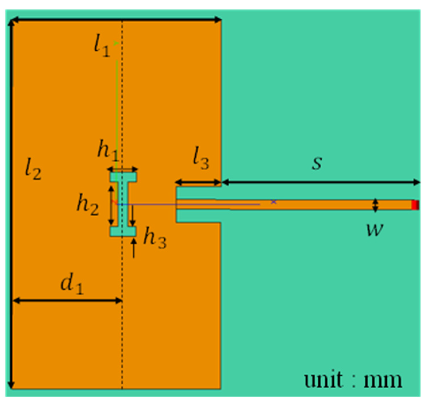
Figure 1 illustrates the proposed antenna. The antenna comprises a two-layer structure. As shown in Figure 1, an H-shaped slotted patch element and microstrip line were placed on the top layer, and the bottom layer was the ground plate. The drain of the amplifying element is assumed to be connected to the microstrip line end. The materials of the conductor and the details of the substrate are shown in Table 1, and the variable ranges of the dimensions in the optimization are presented in Table 2. The input impedance of the microstrip line was set to 100 Ω, which is the optimal load for the amplifying element. The operating frequency of the proposed antenna was set to 5.8 GHz. The parameters in Figure 1 were determined for each part to satisfy the three conditions via optimization. A method using moment-based electromagnetic simulation software was employed for this analysis.
3. Simulation Result
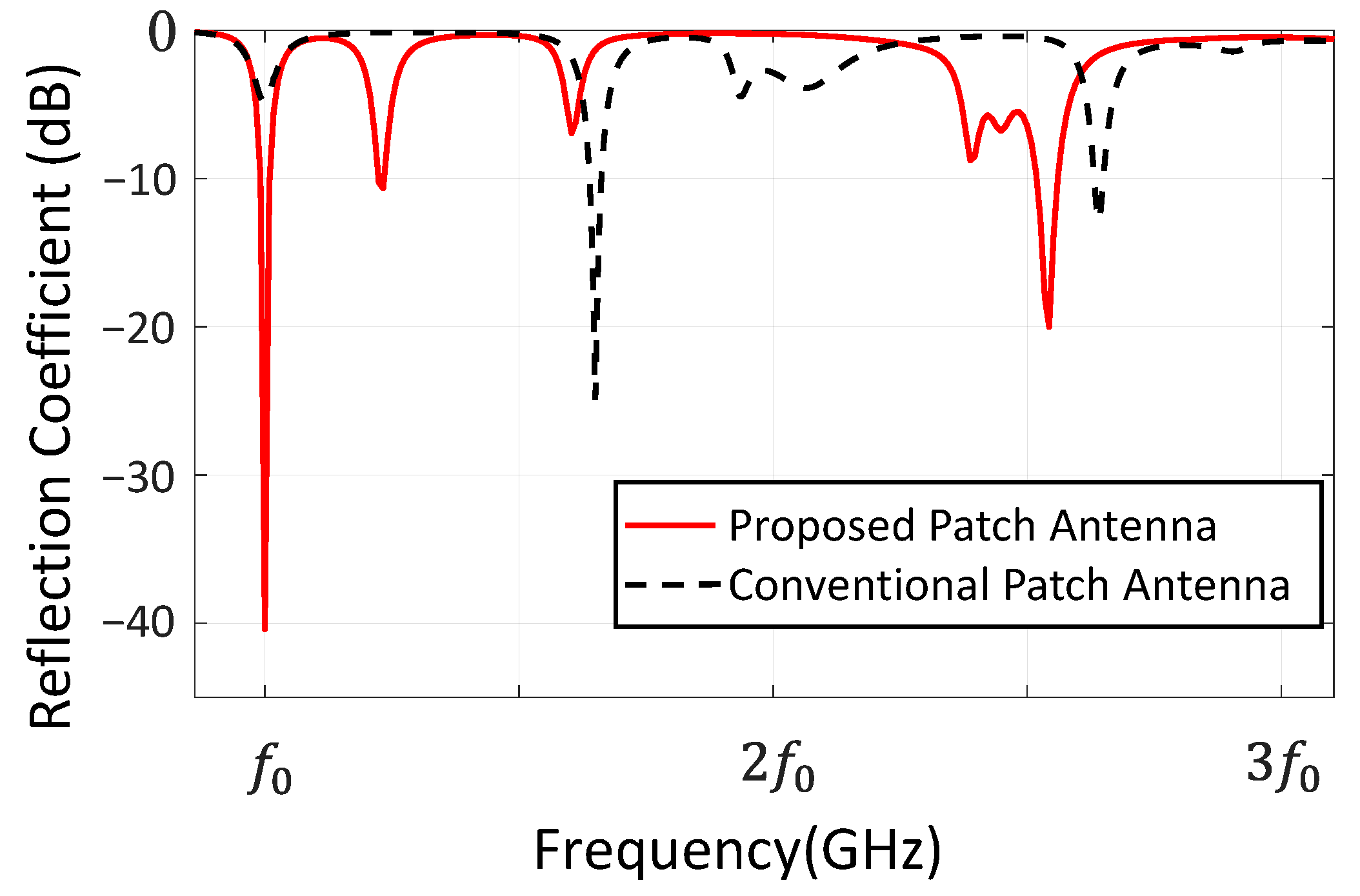
In this section, the proposed antenna is compared with a conventional microstrip patch antenna without a slot to demonstrate the functionality of the H-shaped slot in the antenna. Figure 2 presents the simulated reflection coefficients of the conventional MPA and the proposed antenna. The conventional patch antenna contains the structure of the proposed antenna minus an H-shaped slot. The reference impedance was set to 100 Ω, the optimum load for the amplifying element. The reflection coefficients of the fundamental waves are lower than those of the conventional patch antenna, whereas those of the second- and third-harmonic waves are higher than those of the conventional antenna. This confirms that the H-shaped slot in the patch antenna enables it to handle the harmonics.
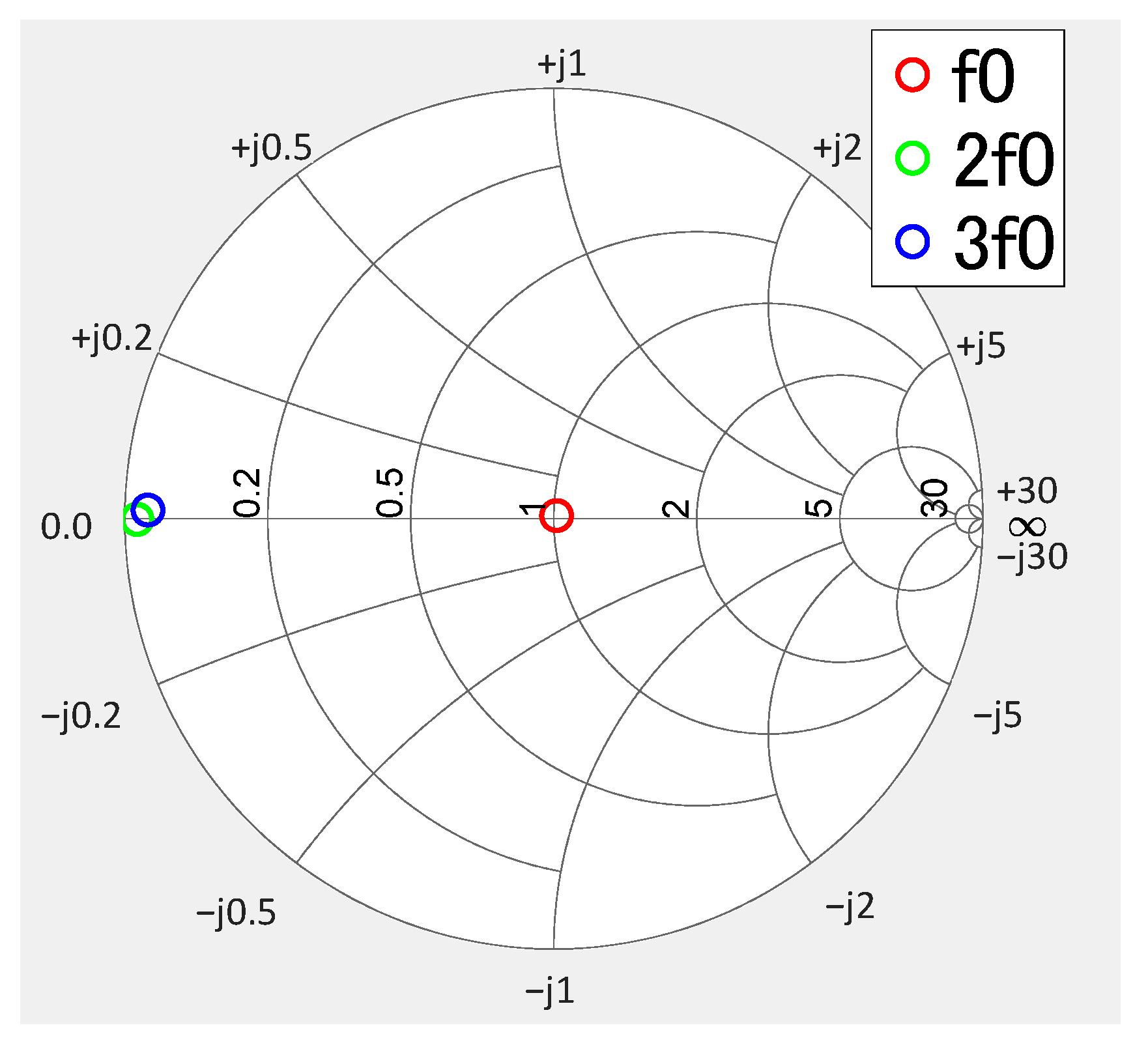
Figure 3 illustrates the simulated reflection coefficients of the antenna at the fundamental frequency, second harmonic, and third harmonic. The reference impedance was 100 Ω, the optimum load for the amplifying element. At the second harmonic, the phase and magnitude of the reflection coefficient were −0.25 dB and −179.9°, respectively. Those at the third-harmonic frequency were −0.48 dB and 178.8°, respectively. It can be confirmed that the proposed antenna satisfies the class-F loading conditions (1), (3), and part of (2). At the third-harmonic frequency, the phase of the reflection coefficient can be changed by adjusting the microstrip line length.
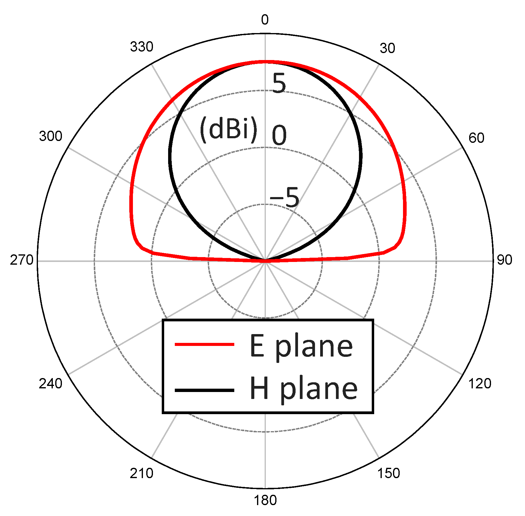
Subsequently, the gain was simulated to confirm the function of the antenna. The gains of the antenna for the E and H planes are illustrated in Figure 4. The maximum gain was 7.52 dBi in the frontal direction of the antenna. The efficiency of the proposed antenna was 95.0%.
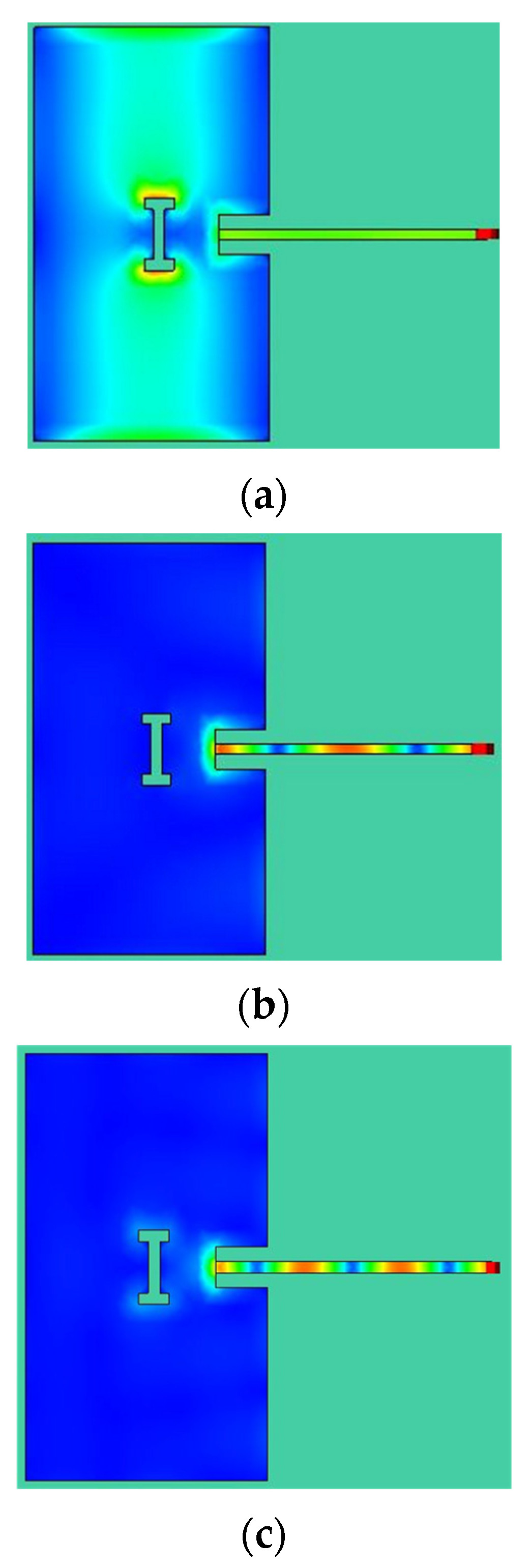
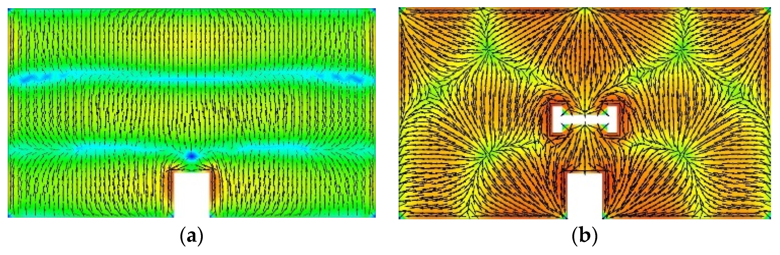
Figure 5 illustrates the current distribution at the fundamental, second-harmonic, and third-harmonic frequencies.
In Figure 5a, the current is an anti-node at the center of the patch element and a node at the edge of the patch element, which corresponds to the behavior of a typical patch antenna.
Figure 5b,c depict that the current on the patch element was very low at the second- and third-harmonic frequencies, indicating that the radiation from the patch element was low.
4. Characteristic Mode Analysis
In this section, the principle of operation is examined from the viewpoints of modal significance and eigenmode current. To investigate the effect of the H-shaped slot, the proposed model was compared with one in which the H-shaped slot was removed.
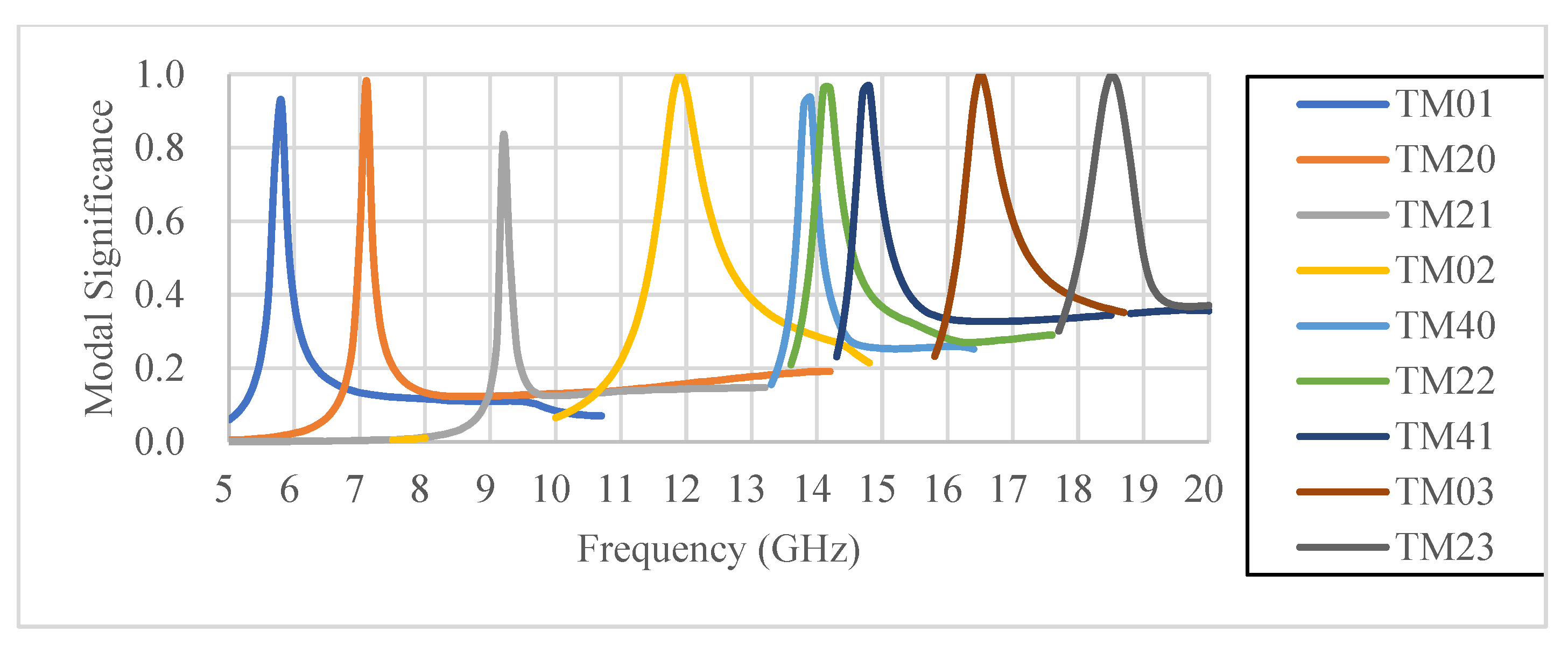
The relationship between the modal significance and the reflection coefficients is illustrated below. Figure 6 presents the frequency response of the modal significance of the model with removed slots. Figure 7 presents the frequency response of the modal significance of the proposed model.
When comparing the frequency characteristics of the two modes, it is evident that the frequencies at which the maxima of each mode occur are different. These changes are most likely caused by the slots. The frequency of the TM (transverse magnetic) 01 mode shifts slightly to a lower frequency. Following the frequency shift, the TM01 mode reaches a maximum of 5.8 GHz. It is assumed that this leads to a lower reflection coefficient at 5.8 GHz. Subsequently, we observed that the frequency of the TM02 mode remains almost unchanged. Therefore, we can ascertain that the slot had minimal effect on the TM02 mode.
The frequency of the TM03 mode shifts significantly to a lower frequency. After the frequency shift, the TM03 mode reaches a maximum at a frequency away from the third-harmonic frequency (17.4 GHz). Accordingly, the reflection coefficient at the frequency of the third harmonic is considered to have increased.
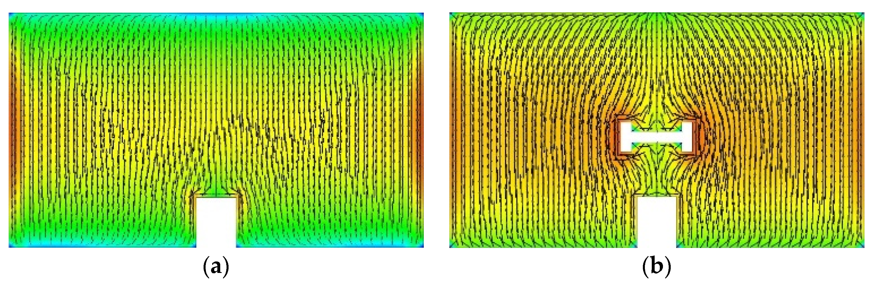
Figure 8 illustrates the current distribution of the TM01 mode. The length of the bypassed current path corresponds to a half-wavelength of 5.8 GHz. Accordingly, the TM01 mode is assumed to have reached its maximum value at 5.8 GHz.
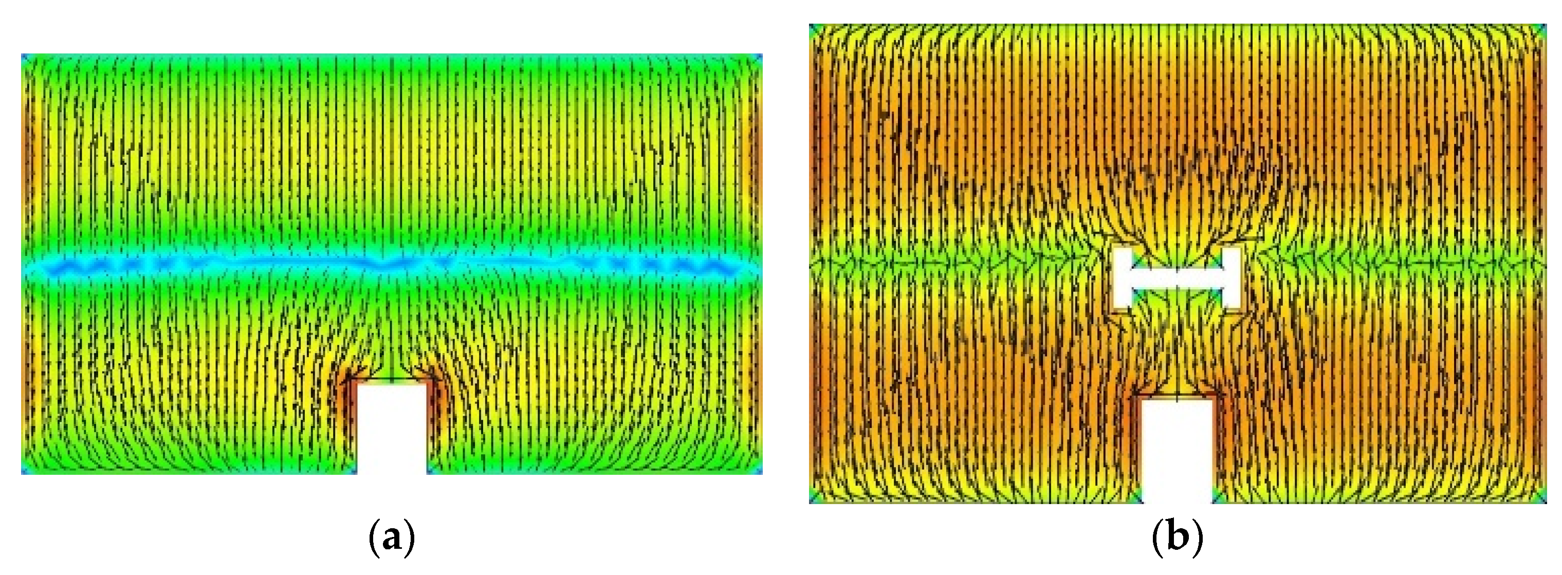
The current distribution in the TM02 mode is shown in Figure 9. The current distribution in the TM02 mode remained almost unchanged because of the slotting of the nodes of the current distribution, as illustrated in Figure 10. Accordingly, the frequency at which the TM02 mode reached its maximum value also remained unchanged.
The current distribution in the TM03 mode is depicted in Figure 10. In the TM03 mode, as shown in Figure 10, most of the current is diverted because a slot is added to the belly of the current distribution. The length of the diverted current path was longer than that of the third-harmonic frequency. Accordingly, the TM03 mode has an extremely low maximum frequency compared to the other modes.
For this antenna, the vertical length of the patch was designed to be smaller than the half-wavelength of the frequency used, 5.8 GHz. The antenna was designed such that resonance occurred at frequencies higher than 5.8 GHz and at integer multiples of these frequencies. Additionally, the resonance frequency changes with the addition of slots. By changing the resonance frequency, the TM01 mode resonates at 5.8 GHz. Therefore, the reflection coefficient is small at the operating frequency of 5.8 GHz. The TM03 mode resonates at approximately 16.5 GHz, which is far from the third-harmonic frequency of 17.4 GHz. Therefore, the reflection coefficient is larger at the third-harmonic frequency.
5. Measurement Result of Proposed Antenna
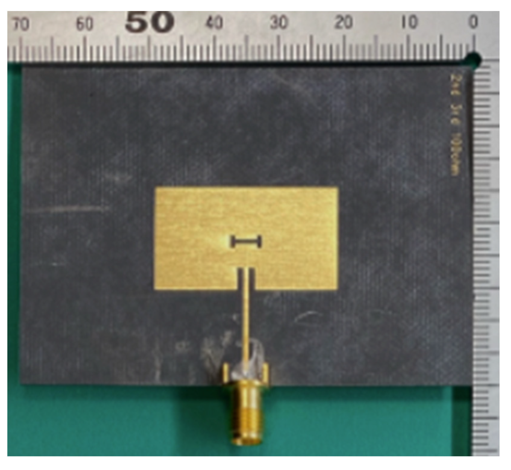
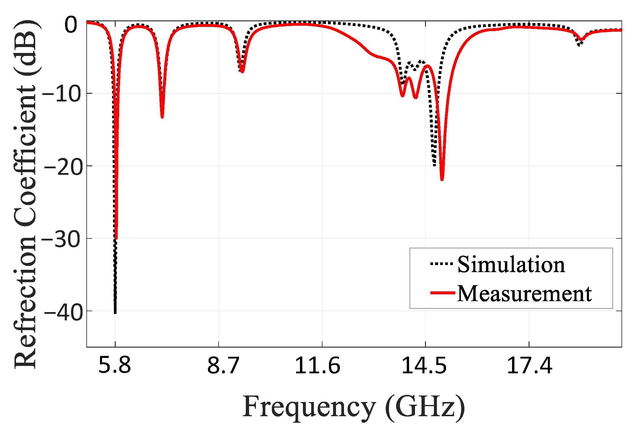
Figure 11 displays a photograph of the fabricated antenna. Figure 12 shows the magnitude of the reflection coefficient when the frequency was swept from 5 to 18 GHz. The reference impedance was 100 Ω, the optimum load for the amplifying element. The resonance frequency was 5.8 GHz for the analysis value and 5.83 GHz for the measurement, resulting in an error of 0.5%. In Figure 12, it is clear that the analytical and measured values are almost identical.
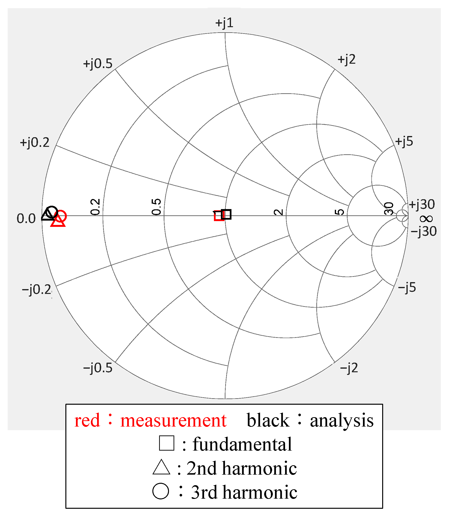
Figure 13 illustrates a Smith chart plot of the reflection coefficients at the fundamental, second-harmonic, and third-harmonic frequencies. At the fundamental frequency, the magnitude of the reflection coefficient was −30.0 dB. At the second-harmonic frequency, the magnitude and phase of the reflection coefficient were −0.79 dB and −177.6°, respectively. At the third-harmonic frequency, they were −0.92 dB and −179.5°, respectively. These results are extremely close to the analytical values, and the fabricated antenna satisfies the class-F loading conditions (1) and (3), as well as part of (2).
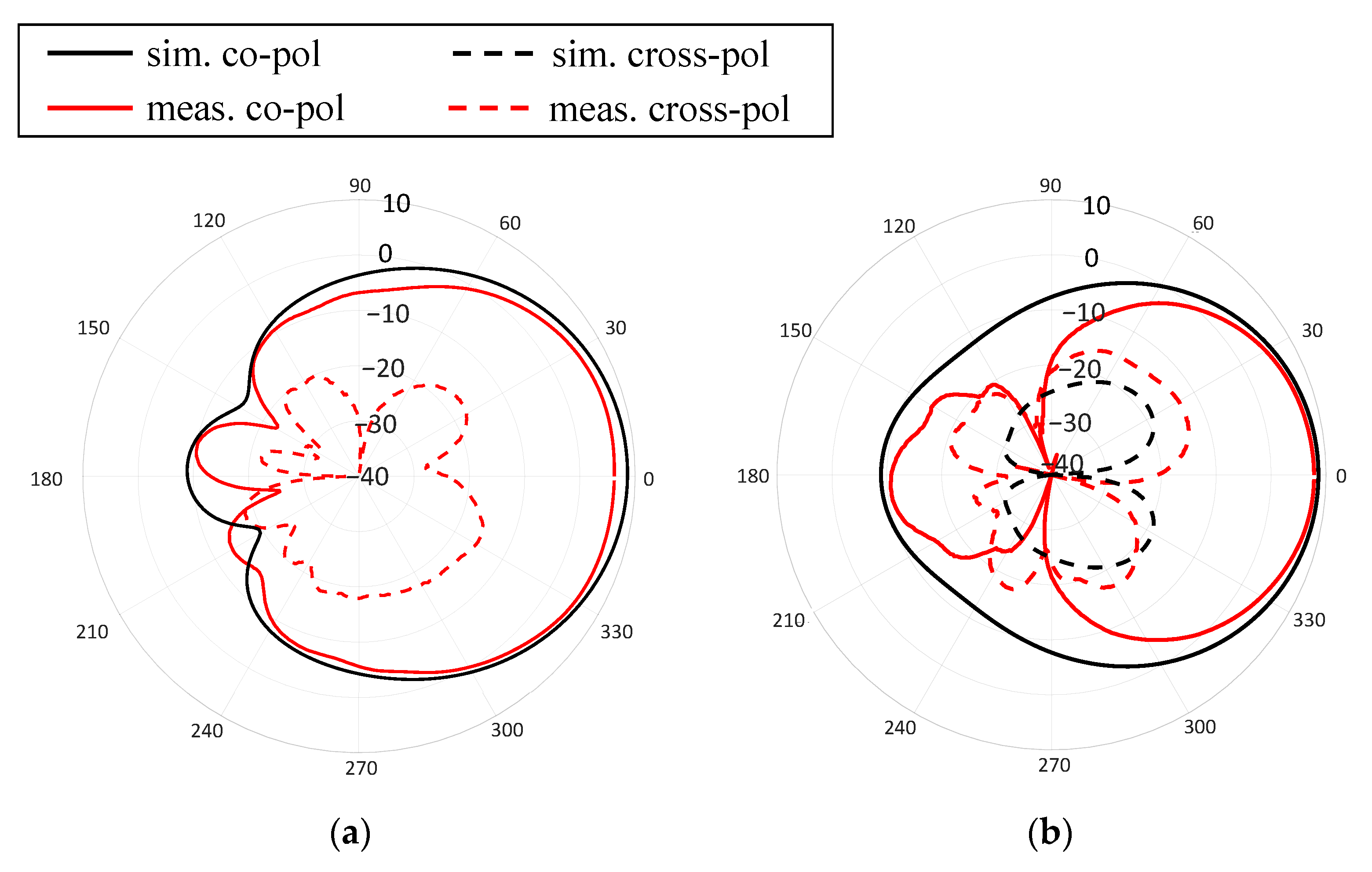
Figure 14 illustrates the measured radiation pattern in the E and H planes at the fundamental frequency. The analytical and experimental values of the co-polarization and cross-polarization agreed in the E and H planes, respectively. The maximum measured gain in the E plane was 6.38 dBi, and that in the H plane was 7.82 dBi. The analytical and measured values for cross-polarization were less than −20 dBi in both the E and H planes.
6. Discussion
This study proposed a harmonic-processing antenna as a transmitting antenna for microwave power transfer. The motivation for this is that the antenna has some of the functions of the amplifier, and the integrated design with the amplifier facilitates minimizing the size of the system. Therefore, an H-shaped patch antenna was proposed, analyzed, and measured. We also investigated the principle of harmonic processing using CMA to understand the mechanism of harmonic rejection.
Table 3 presents a comparison of the antennas proposed in this study with those described in [9,13,14,15,16]. The table compares them in terms of the reflection coefficient at each frequency with and without phase adjustment, gain, and antenna efficiency. From this comparison, it is evident that the fundamental matching performance, gain, and efficiency of the proposed antenna are suitable for MPT. The harmonic-processing performance of the proposed antenna is worse than that of other antennas; however, it is superior to that of a phase-tuned antenna [16]. Therefore, it is possible to reduce the switching losses of the amplifier and enhance its efficiency.
The proposed antenna is capable of handling harmonics by providing H-shaped slots to conventional microstrip antennas. This principle was investigated using CMA. By introducing the H-shaped slot, the anti-node of the current path is bypassed at the fundamental frequency, and the current path is longer than the length of the patch element. The H-shaped slot is located at a node in the current distribution at the second- and third-harmonic frequencies and does not affect the current path. Thus, by introducing H-shaped slots in the patch element, which has the function of processing the second and third harmonics, only the current path of the fundamental wave is affected, and the fundamental wave is also matched. This technology could be used in antennas for beyond-5G and other microwave power transfer systems to process more harmonics.
7. Experimental Results of Power-Amplifier–Integrated Antenna
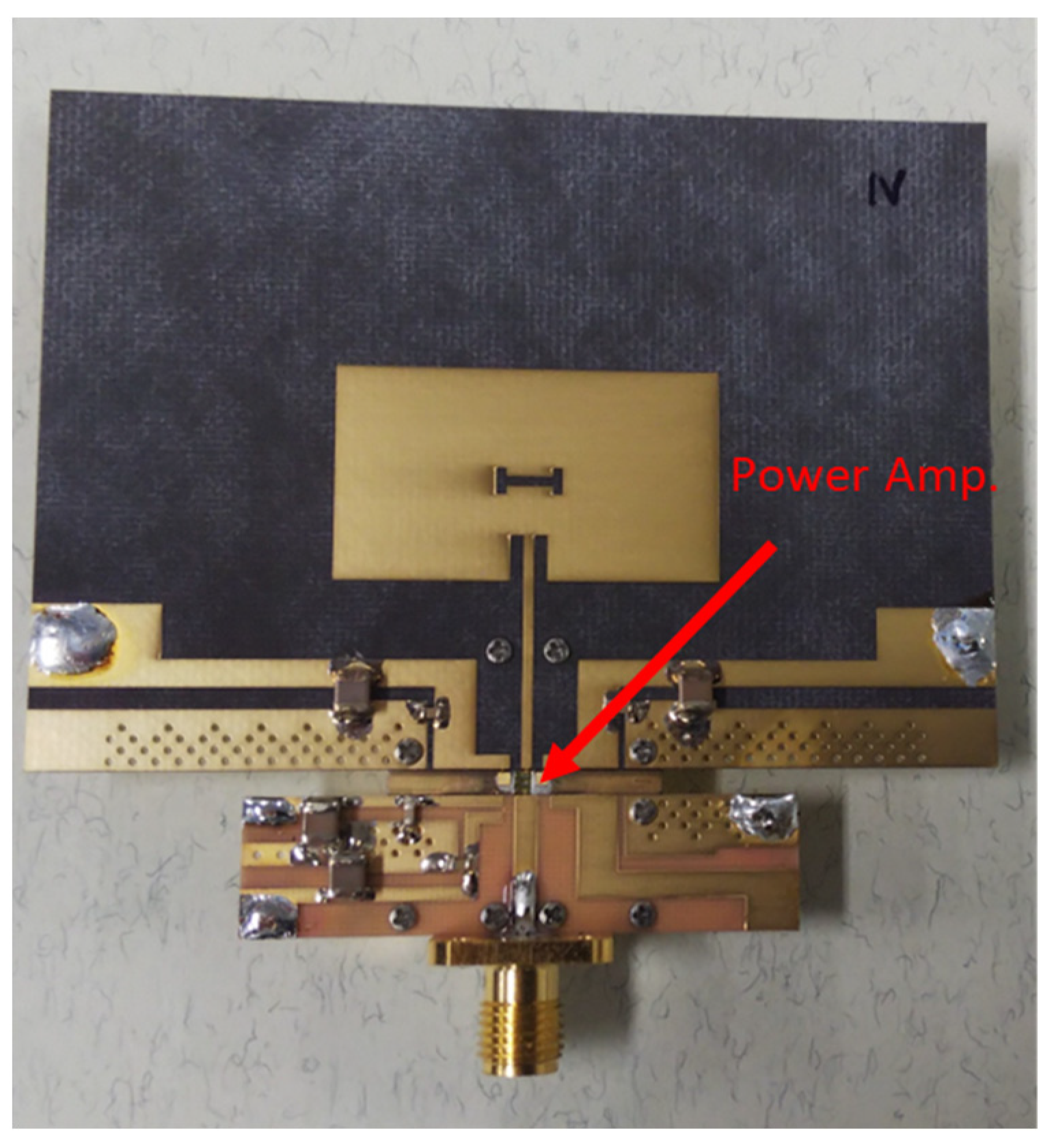
Measurements were performed to evaluate the performance of the power-amplifier-integrated antenna and the effectiveness of the proposed antenna. Figure 15 displays a photograph of the fabricated power-amplifier-integrated antenna, which integrates a two-layer patch antenna with an H-shaped slot with a power amplifier. The proposed harmonic tuning antenna is directly connected to the drain of the power amplifier element without using a matching circuit because the harmonic tuning antenna has the optimal load impedance of the power amplifier. Although the optimal load impedance is a complex value, the imaginary part is realized by the bias circuit. Thus, the H-shaped slot antenna provides real impedance for the fundamental frequency. The reflection phase of the harmonics can be tuned by the connecting line length between the power amplifier chip and the antenna element without having to worry about the fundamental wave impedance change.
The performance of the power amplifier inside the power-amplifier-integrated antenna and the power amplifier with the tuner reproducing the impedance of the H-shaped slot patch antenna were compared to confirm the correlation. Upon confirming this correlation, an experiment was conducted to determine the effect of the harmonic reflection function of an H-slot antenna.
Power amplifier performance within the power-amplifier-integrated antenna was calculated using the procedure described below. The power propagation test with a power-amplifier-integrated antenna was performed in a Candox Systems 44St26A3 anechoic chamber. The power-amplifier-integrated antenna was set in the direction of maximum power reception, and the effective isotropic radiation power (EIRP) was derived from the value of the received power. The output power of the power amplifier was calculated from the EIRP value based on the antenna gain, which was evaluated separately.
When evaluating the power amplifier using the tuner, the impedance of the H-shaped slot patch antenna was measured up to the third harmonic, and the impedance was reproduced by the third-harmonic tuner following the removal of the influence of the connector during the measurement, and the power amplifier performance was measured using the tuner.
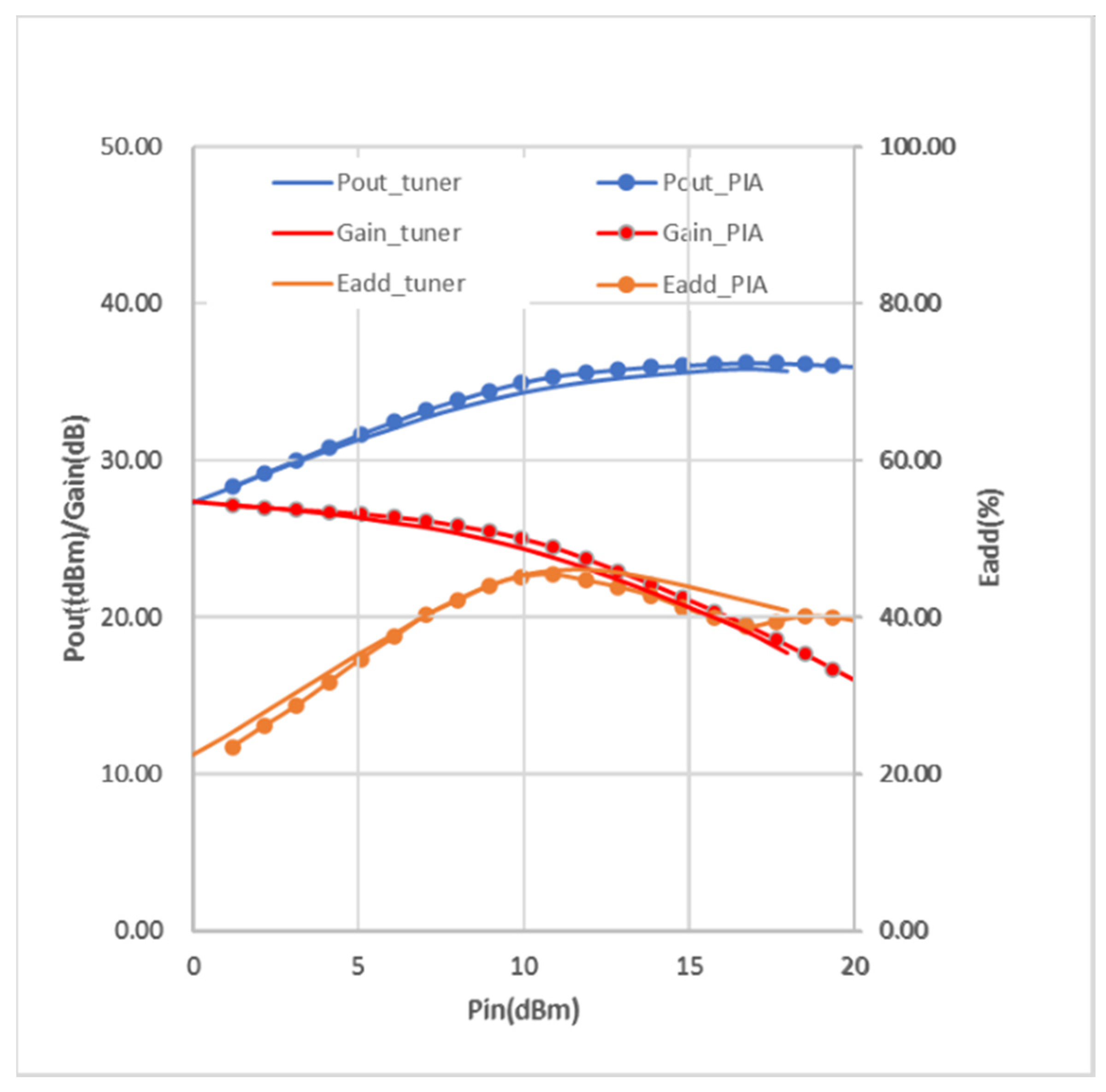
The results are illustrated in Figure 16. The maximum gain of the amplifier was 27.1 dB for an input power of 1 dBm. The maximum power-added efficiency was 44% for an input power of 11 dBm, which was not so high because this report was to show the concept and demonstration of a power-amplifier-integrated antenna. We will improve the performance by using a newly designed power amplifier chip and optimizing the length between the power amplifier and the antenna element.
The measured values agreed well, and we believe that the power amplifier performance inside the power-amplifier-integrated antenna was reproduced by the tuner load.
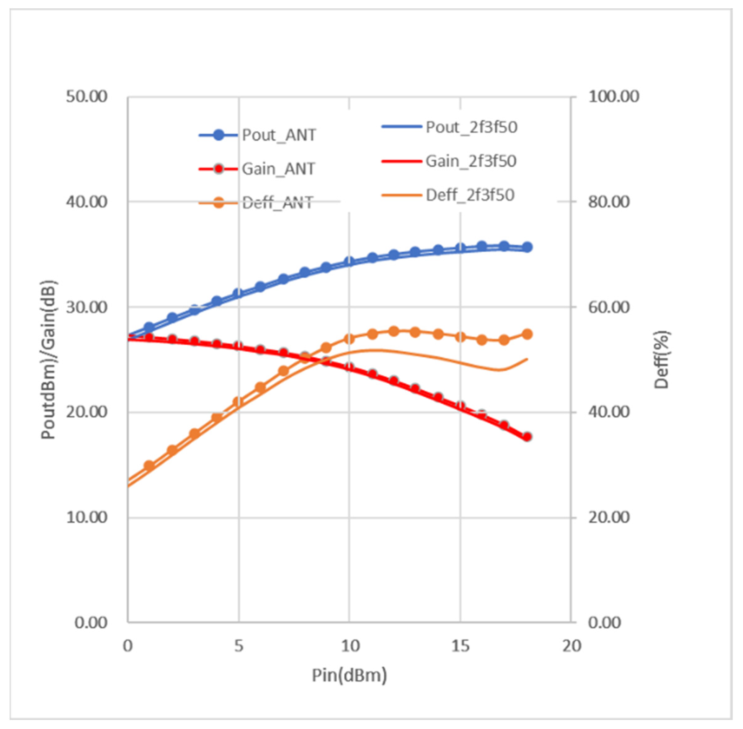
To confirm the effect of harmonic reflections, the second- and third-harmonic impedances in the tuner were set to low reflection values, ideally zero. Figure 17 compares those results with the results of the performance of the power amplifier with the H-shaped slot patch antenna, which has a high reflection coefficient of the second and third harmonics. The drain efficiency decreased by 5.5% compared with the antenna impedance. This result shows the effects of the harmonic reflection function of the H-shaped slot patch antenna. Further improvements can be expected by adjusting the phase of the connection with the power amplifier.
8. Conclusions
A two-layer patch antenna with an H-shaped slot with a harmonic rejection function has been proposed. The model was designed to satisfy the impedance conditions of matching at the fundamental frequency (5.8 GHz), which is short at the second-harmonic frequency (11.6 GHz), and has a high reflection coefficient at the third-harmonic frequency (17.4 GHz). Experiments in the 5.8 GHz range confirmed a reflection coefficient of −30.0 dB for the fundamental frequency, −0.79 dB and −177.6° for the second-harmonic frequency, and −0.92 dB and −179.5° for the third-harmonic frequency. The measured gain was 7.82 dBi.
The operating principle of the antenna was also investigated by using CMA. The size of the proposed antenna is smaller than the half wavelength of the fundamental frequency (5.8 GHz). For this reason, this antenna was de-tuned for 5.8 GHz, 11.6 GHz, and 17.4 GHz. Therefore, reflection coefficient of the 11.6 GHz and 17.4 GHz increased. The H-shaped slots detour the current path only for the fundamental frequency. Accordingly, input impedance at 5.8 GHz was adjusted to the desired value.
The proposed antenna was integrated with an amplifier to verify whether the drain efficiency of the power amplifier was realized with the proposed antenna when the impedance tuner was directly connected.
The maximum gain of the integrated amplifier was 27.1 dB for an input power of 1 dBm. It was confirmed that the drain efficiency improved by 5.5% by using the proposed harmonic tuning antenna.
It was further investigated how to make the third-harmonic impedance open to achieve the class-F function condition. We believe that the highly efficient power-amplifier-integrated antenna can contribute to the higher efficiency of wireless power transfer. In addition, the proposed antenna design technique can be used to reduce the size of the antenna for beyond-5G applications. The tuning of the third-harmonic phase to fully satisfy the class-F condition is an area for further study.
Author Contributions
Writing—original draft, Y.N., K.N., N.T., S.H. and H.H.; Supervision, H.H.; Funding acquisition, S.H. and H.H. All authors have read and agreed to the published version of the manuscript.
Funding
This work was supported by the Council for Science, Technology and Innovation (CSTI); Cross-ministerial Strategic Innovation Promotion Program (SIP); and “Energy systems of an Internet of Energy (IoE) society” (funding agency: JST).
Conflicts of Interest
The authors declare no conflict of interest.
References
- Hashimoto, Y.; Yuan, Q.; Aoki, T. Drone Driven by Microwave. In Proceedings of the 2018 Asia-Pacific Microwave Conference (APMC), Kyoto, Japan, 6–9 November 2018; pp. 1444–1446. [Google Scholar]
- Kuroda, K.; Ishikawa, R.; Honjo, K. High-Efficiency GaN-HEMT Class-F Amplifier. In Proceedings of the 38th European Microwave Conference, Amsterdam, The Netherlands, 27–31 October 2008; pp. 440–443. [Google Scholar]
- Gao, S.; Butterworth, P.; Sambell, A.; Sanabria, C.; Xu, H.; Heikman, S.; Mishra, U.; York, R.A. Microwave Class-F and Inverse Class-F Power Amplifiers Designs using GaN Technology and GaAs pHEMT. In Proceedings of the 2006 European Microwave Conference, Manchester, UK, 10–15 September 2006; pp. 1719–1722. [Google Scholar]
- Abe, Y.; Ishikawa, R.; Honjo, K. Inverse Class-F AlGaN/GaN HEMT Microwave Amplifier Based on Lumped Element Circuit Synthesis Method. IEEE Trans. Microw. Theory Technol. 2008, 56, 2748–2753. [Google Scholar] [CrossRef]
- Lin, X.C.; Wang, L.T. A broadband CPW-fed loop slot antenna with harmonic control. IEEE Antennas Wirel. Propag. Lett. 2003, 2, 323–325. [Google Scholar]
- Beltran, R.A. Class-F Inverse Class-F Power Amplifier Lading Networks Design Based upon Transmission Zeros. In Proceedings of the IEEE MTTS International Microwave Symposium, Tampa, FL, USA, 1–6 June 2014. [Google Scholar]
- Radisic, V.; Qian, Y.; Itoh, T. Class F power amplifier integrated with circular sector microstrip antenna. 1997 IEEE MTTS Intl. Microw. Symp. Dig. 1997, 2, 687–690. [Google Scholar]
- Radisic, V.; Qian, Y.; Itoh, T. Novel architectures for high-efficiency amplifiers for wireless applications. IEEE Trans. Microw. Theory Technol. 1998, 46, 1901–1909. [Google Scholar] [CrossRef] [Green Version]
- Acharjee, J.; Mandal, K.; Mandal, S.K.; Sarkar, P.P. Rejection and Control of Higher Harmonics in a Microstrip Patch Antenna by using Defected Ground Structure. In Proceedings of the IEEE International Conference on Microelectronics, Computing and Communication, Durgapur, India, 23–25 January 2016. [Google Scholar]
- Biswas, S.; Guha, D.; Kumar, C. Control of higher harmonics and their radiations in microstrip antennas using compact defected ground structures. IEEE Trans. Antennas Propagat. 2013, 61, 3349–3353. [Google Scholar] [CrossRef]
- Pattapu, U.; Miriyala, S. A 5.80 GHz Harmonic Suppression Antenna for Wireless Energy Transfer Application. In Proceedings of the 2022 2nd International Conference on Artificial Intelligence and Signal Processing (AISP), Changsha, China, 12–14 February 2022; pp. 1–4. [Google Scholar]
- Sung, Y.J.; Kim, Y.S. An improved design of microstrip patch antennas using photonic band gap structure. IEEE Trans. Antennas Propagat. 2005, 53, 1799–1804. [Google Scholar] [CrossRef]
- Dehbashi, R.; Atlasbaf, Z.; Forooraghi, K. New compact size microstrip antennas with harmonic rejection. IEEE Antennas Wirel. Propagat. Lett. 2006, 5, 395–398. [Google Scholar] [CrossRef]
- Li, W.; Li, P.; Zhou, J.; Liu, Q.H. Control of higher order harmonics and spurious modes for microstrip patch antennas. IEEE Access 2018, 6, 34158–34165. [Google Scholar] [CrossRef]
- Chou, J.H.; Lin, D.B.; Tien, L. A Compact Shorted Patch Rectenna Design with Harmonic Rejection Properties. In Proceedings of the International Symposium on Antennas and Propagation (ISAP), Okinawa, Japan, 24–28 October 2016. [Google Scholar]
- Mao, C.X.; Gao, S.; Wang, Y.; Cheng, Z. Filtering antenna with two-octave harmonic suppression. IEEE Antennas Wirel. Propagat. Lett. 2016, 16, 1361–1364. [Google Scholar] [CrossRef]
- Schmid, C.M.; Itoh, T.; Stelzer, A. A Power Amplifier Integrated with a Composite Right/Left-Handed Metamaterial Antenna. In Proceedings of the Asia Pacific Microwave Conference, Singapore, 7–10 December 2009; pp. 321–324. [Google Scholar]
- Liw, S.; Ellis, G.A. Planar inverted-F antennas as an inverse class-F termination for wireless applications. IEEE Antennas Wirel. Propagat. Lett. 2003, 2, 250–253. [Google Scholar] [CrossRef]
- Oshima, T.; Ban, S.; Hirayama, H. Microstrip patch antenna with class-F load and DC block function for microwave power transfer. IEICE Electron. Expr. 2021, 18, 20210264. [Google Scholar] [CrossRef]
- Hara, S.; Suzuki, A.; Hirayama, H. Proposal and Demonstration of Power Conversion-Chip/Amplifier Integrated Antenna. In Proceedings of the 2020 50th European Microwave Conference (EuMC), Sevilla, Spain, 12–14 January 2021. [Google Scholar]
- Narita, Y.; Nozawa, K.; Hirayama, H. Characteristic Mode Analysis of H-shaped Slot Patch Antenna with Class-F Load Function. In Proceedings of the Wireless Power Week (WPW), Bordeaux, France, 5–8 July 2022. [Google Scholar]
Figure 1.
Proposed antenna model and its parameters.

Figure 2.
Reflection coefficient of the proposed patch antenna and conventional patch antenna (simulation).
Figure 2.
Reflection coefficient of the proposed patch antenna and conventional patch antenna (simulation).

Figure 3.
Impedance of the proposed patch antenna at fundamental (f0) and second (2f0)- and third (3f0)-harmonic frequencies (simulation).
Figure 3.
Impedance of the proposed patch antenna at fundamental (f0) and second (2f0)- and third (3f0)-harmonic frequencies (simulation).

Figure 4.
Antenna gain pattern (simulation).

Figure 5.
Current distribution of the proposed patch antenna. (a) Fundamental frequency. (b) Second-harmonic frequency. (c) Third-harmonic frequency.
Figure 5.
Current distribution of the proposed patch antenna. (a) Fundamental frequency. (b) Second-harmonic frequency. (c) Third-harmonic frequency.

Figure 6.
Modal significance of the proposed patch antenna without slot.

Figure 7.
Modal significance of the proposed patch antenna with the slot.

Figure 8.
Current distribution of the TM01 mode. (a) Conventional patch antenna. (b) Proposed H-slot antenna.
Figure 8.
Current distribution of the TM01 mode. (a) Conventional patch antenna. (b) Proposed H-slot antenna.

Figure 9.
Current distribution of the TM02 mode. (a) Conventional patch antenna. (b) Proposed H-slot antenna.
Figure 9.
Current distribution of the TM02 mode. (a) Conventional patch antenna. (b) Proposed H-slot antenna.

Figure 10.
Current distribution of the TM03 mode. (a) Conventional patch antenna. (b) Proposed H-slot antenna.
Figure 10.
Current distribution of the TM03 mode. (a) Conventional patch antenna. (b) Proposed H-slot antenna.

Figure 11.
Photograph of the fabricated antenna.

Figure 12.
Reflection coefficient of the proposed patch antenna (measurement and simulation).

Figure 13.
Impedance of the proposed patch antenna at fundamental and each harmonic frequency (measurement and analysis). The reference impedance is 100 ohm, the optimal load impedance of the integrated power amplifier.
Figure 13.
Impedance of the proposed patch antenna at fundamental and each harmonic frequency (measurement and analysis). The reference impedance is 100 ohm, the optimal load impedance of the integrated power amplifier.

Figure 14.
Antenna gain at fundamental frequency (5.8 GHz). (a) E plane. (b) H plane.

Figure 15.
Photograph of the fabricated power-amplifier-integrated antenna.

Figure 16.
The measured output power, gain, and power added efficiency. The trace of “PIA” is the measurement result of the power-amplifier-integrated antenna shown in Figure 15. The trace of “tuner” is the measured value when the power amplifier is directly connected to an impedance tuner whose impedance was set to the antenna impedance shown in Figure 3.

Figure 17.
Effect of the harmonic reflection function of the antenna on the output power, gain, and drain efficiency of the amplifier. These results are the measured values when an impedance tuner is connected to the amplifier as a load impedance. The trace “_ANT” shows the measured value when the antenna impedance for the fundamental, second-harmonic, and third-harmonic frequencies shown in Figure 3 are set to the impedance tuner. The trace “_2f3f50” shows the measured value when the impedance for harmonic antenna impedance for the fundamental frequency shown in Figure 3 is set to the tuner, but an impedance of 50 ohm is set for the second- and the third-harmonic frequency.


Table 1.
Material and dimension of the substrate during optimization.
| Material of the Conductor | PEC |
| Material of the substrate | Rogers RT5880 (, ) |
| Thickness of the substrate | 0.787 mm |
| Area of the substrate | Infinite plane |
Table 2.
Designed range and definition of each parameter.
| Parameters | Definition | Variation Range (mm) | Designed Value (mm) |
|---|---|---|---|
| Length of the strip line | 10–30 | 18.32 | |
| Width of the strip line | 0.75 | 0.75 | |
| Horizontal dimension of the patch element | 10–20 | 16.05 | |
| Vertical dimension of the patch element | 10–35 | 28.30 | |
| Penetration length | 0.5–5 | 3.45 | |
| Horizontal dimension of the H-shaped slot | 0.1–6 | 2.03 | |
| Vertical dimension of the H-shaped slot | 1.0–8.0 | 3.40 | |
| Width of the H-shaped slot | 0.1–1.5 | 0.76 | |
| Location of the H-shaped slot | 0–10 | 8.525 |
Table 3.
Comparison with other harmonic-suppression antennas.
| Design Technique | Phase | Antenna Efficiency (%) | |||||
|---|---|---|---|---|---|---|---|
| This Work | H-Shaped Slot | 〇 | |||||
| [9] | Stub, DGS | × | |||||
| [13] | U-Shaped Slot | × | |||||
| [14] | Edge Patch | × | |||||
| [15] | U-Shaped Slot | × | .0 | ||||
| [16] | PIFA | × | |||||
| [18] | Shorting Pins | 〇 |
* Read value from figure. †: simulation value. 〇: with adjustment function. ×: without adjustment function. NA: not designated.
Disclaimer/Publisher’s Note: The statements, opinions and data contained in all publications are solely those of the individual author(s) and contributor(s) and not of MDPI and/or the editor(s). MDPI and/or the editor(s) disclaim responsibility for any injury to people or property resulting from any ideas, methods, instructions or products referred to in the content. |
© 2023 by the authors. Licensee MDPI, Basel, Switzerland. This article is an open access article distributed under the terms and conditions of the Creative Commons Attribution (CC BY) license (https://creativecommons.org/licenses/by/4.0/).
Share and Cite
MDPI and ACS Style
Narita, Y.; Nozawa, K.; Tanba, N.; Hara, S.; Hirayama, H. H-Shaped Slot Antenna with Harmonic Tuning Function and Integrated Power Amplifier. Energies 2023, 16, 2128. https://0-doi-org.brum.beds.ac.uk/10.3390/en16052128
AMA Style
Narita Y, Nozawa K, Tanba N, Hara S, Hirayama H. H-Shaped Slot Antenna with Harmonic Tuning Function and Integrated Power Amplifier. Energies. 2023; 16(5):2128. https://0-doi-org.brum.beds.ac.uk/10.3390/en16052128
Chicago/Turabian StyleNarita, Yuto, Koichi Nozawa, Noriyuki Tanba, Shinji Hara, and Hiroshi Hirayama. 2023. "H-Shaped Slot Antenna with Harmonic Tuning Function and Integrated Power Amplifier" Energies 16, no. 5: 2128. https://0-doi-org.brum.beds.ac.uk/10.3390/en16052128
Note that from the first issue of 2016, this journal uses article numbers instead of page numbers. See further details here.