1. Introduction
Mechanical systems in many safety critical applications such as vehicles (e.g., cars, trains, motorcycles) and biomedical devices (e.g., robotized prosthetic arms or legs to improve the quality of life of elderly, wounded, and disabled people with temporary or permanent handicaps) are becoming mechatronic systems with electric actuation. The latter is controlled through embedded hardware-software electronic units [
1,
2,
3,
4,
5,
6,
7,
8,
9,
10,
11,
12,
13,
14,
15]. State-of-the-art mechanical, hydraulic, pneumatic, oleo-dynamic actuation systems have been substituted with electric motors, electro-valves, electromagnetic injectors, piezoelectric and voice coil actuators in applications such as engine control, automatic transmission, brake/steer assistance, door systems (latch, window lifter), and wearable robotized prosthesis for an injured hand, arm or leg. Most of such systems are powered with battery modules. Lithium cells are gaining in the market compared to mature lead-acid, nickel-cadmium (NiCd), nickel-metal hydride (NiMH) or nickel-iron (NiFe) technology for their superior energy density (Wh/Kg), but there is a higher risk of faults [
16,
17,
18,
19,
20,
21]. One of the key issues still to be solved in terms of the reliability of electrically actuated mechatronic systems in safety critical applications [
22] is how to face failures of the energy source,
i.e. the main battery, due to crashes, to problems in the connecting wires, or to cranking at the start phase of the system. For example, in real production vehicles, most of sub-systems are still mechanically actuated or the electric/electronic part is only an ancillary function. The main reason is that a pure electronic control and actuation is not yet considered to be as reliable as its mechanical counterpart. In many brake, steering, and door control systems, the electric actuation is added to the mechanical one to increase the comfort of the driver with extra functionalities. However, the co-existence of both types of actuators increases system cost, weight, and size.
The current solution to the reliability problem of electric actuators is to try to reduce the risks of an energy failure by adopting redundant modules for the main battery or using multiple main batteries. To avoid increasing the system size and weight too much, the most suitable solution for battery backup is using lithium-cells; however, they do suffer from reliability problems above 60 °C [
16] or at subzero temperatures [
23]. On the contrary, in this paper, we exploit the idea of increasing the reliability of each electric actuator by embedding a compact and low-cost local energy storage resource. In the case of main battery failure, this local energy backup provides the required power for the required time to guarantee actuator operation until the system enters into safety mode. Proper switching regulator circuitry is also needed to provide the correct voltage/current levels to the load. The proposed actuator control unit (ACU) architecture is scalable in terms of managed input/output channels, and in terms of managed current/voltage levels and hence of managed power level. In this way, the same architecture can be used to address different application cases. In this paper, this scalability will be demonstrated addressing three different application cases: (i) a robotic arm for assisted living of elderly/disabled people; (ii) a robotized gearbox for a formula SAE (Society of Automotive Engineers) race car; (iii) a mechatronic door with electric actuation of latch (E-latch) in a car. So far, backup actuator energy systems based on supercapacitors have been discussed, but these studies have been limited to high power applications using supercapacitors of thousands of farads [
24,
25,
26], and with temperature characterizations limited to 70 °C [
25,
26]. Conversely, many ACUs used in robotics or vehicle applications require supercapacitors of tens of farads to sustain a burst of tens or hundreds of watts for only a few seconds, in an extended temperature range above 70 °C.
This work extends the author’s conference contribution in another work [
6], which was limited to biomedical applications only, and which did not consider the harsh requirements in terms of temperature, durability, and electrostatic discharge (ESD) protection of the vehicle application scenario. To this aim, durability, electrical, and temperature tests, the latter up to 130 °C, were carried out in this work. The main contribution of this work is the presentation of an ACU, optimized for applications up to hundreds of joules in harsh operating conditions, for which:
Tolerance to faults of the main energy source in electric actuators is obtained, avoiding the use of a mechanic or hydraulic backup, as seen elsewhere [
27], which increases system size and weight.
An extended temperature-range characterization is done for the energy backup, whereas recent works using lithium batteries or supercapacitors are typically limited at 70 °C [
25,
26].
The energy backup unit is optimized for safety-critical ACUs, providing a burst of hundreds of watts in only a few seconds, largely present in robotics and vehicular systems, and using supercapacitors of a few, or tens of, farads. Alternatively, backup units are often optimized for high power systems (tens of kWs or above) using supercapacitors of thousands of farads [
24,
25,
26,
28,
29,
30,
31,
32,
33,
34]. Supercapacitors with lower values are used in the literature for the backup of computing/communication digital devices [
23,
26], whereas the aging characterization at high temperatures is often missing.
Hereafter,
Section 2 presents the new ACU architecture, while
Section 3 and
Section 4 detail the energy storage subsystem based on supercapacitors and characterize the performance degradation of the energy storage devices after 10,000 cycles and in a wide temperature range.
Section 5 and
Section 6 present the results when applying the new mechatronic controller unit in different implementation scenarios such as biomedical and automotive robotics. Conclusions are drawn in
Section 7.
2. Mechatronic Actuator Control Unit Architecture
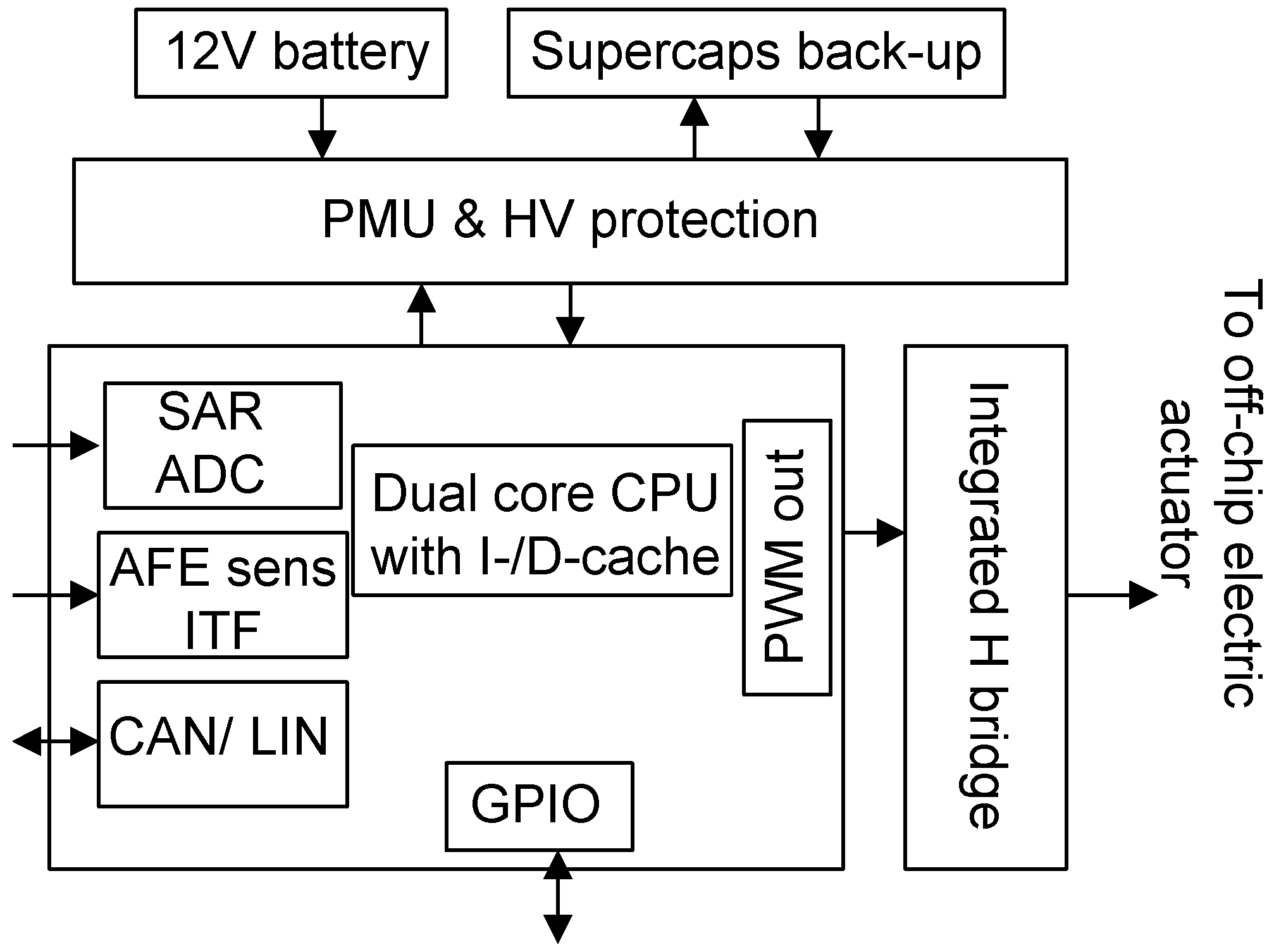
The proposed ACU architecture is modular and can be implemented in a single printed circuit board (PCB). It is composed by an integrated circuit (IC) (
Figure 1) for sensor signal interfacing, digital control processing, and networking plus off-chip devices for energy backup storage and power actuation. The IC includes a low-voltage domain, with a microcontroller core enhanced with Local Interconnect Network (LIN) and Controller Area Network (CAN) connectivity towards host computers, multiple pulse width modulation (PWM) output channels, multiplexed 10-bit A/D converters with successive-approximation register (SAR) topology, and analog front-end (AFE) sensor interfaces (ITF). The digital device integrates for redundancy a dual core 32-bit CPU core of the ARM Cortex family. Each core includes the following blocks: high efficiency dual issue superscalar pipeline with a computational capability of 2.5 MIPS/MHz, floating-point unit coprocessor for the acceleration of computing intensive algorithms, 32 kB of instruction memory, and 32 kB of data cache memory. A 32-b timer/counter and a watchdog timer complete the controller core. For this part, 0.18-μm semiconductor technology is used. To save power consumption when the mechatronic actuator is in standby, the proposed ACU can operate in two modes:
“Standard mode” when all the sub-units are working in full power mode.
“Low-power mode” when all the devices are off, with a residual current of a few µA. The ACU is woken up by the watchdog timer or an external interrupt to return to normal mode.
A high-voltage domain, still realized in 0.18-μm technology, is integrated in the same chip with a power management unit (PMU) and some protection circuitry to interface the low voltage domain to the battery power supply, which is typically 12 or 24 V. The PMU integrates a step-down switching converter to provide the supply voltage to all electronics (1.8, 3.3, and 5 V levels) starting from a nominal 12 or 24 V, plus a boost converter to step up, in the case of battery failure, the voltage level provided by the energy storage backup unit based on supercapacitors.
The IC in
Figure 1 is interfaced to off-chip electromagnetic actuators (e.g., electric valves, injectors, or an electric motor) through power MOSFETs with integrated driver. In the proposed realization, the integrated power driver incorporates a dual monolithic high-side driver and two low side switches, with Power MOSFET and intelligent signal/protection circuitry, all in a MultiPowerSO-30 package on electrically isolated lead frames. This device sustains PWM actuator control up to 20 kHz, with voltage and current levels of 60 V and 40 A, and a maximum power of 2 kW. Therefore, the limits in the proposed design for the actuator that can be selected are the maximum frequency (20 kHz) and the maximum power (2 kW). As will be demonstrated in
Section 5 and
Section 6, these values are not a practical limit for most of the actuators used in target applications such as robotized prosthetic arms/legs, robotized gearboxes in cars, and mechatronic doors for latch openings.
Other off-chip passive devices are integrated in the same PCB board such as supercapacitors for local energy backup, shunt resistors, and hall sensors for current monitoring. Thermal resistors are integrated on-chip in all-integrated circuits for over-temperature protection: When the sensed temperature is beyond a pre-set threshold, then a comparator generates a signal that forces the shutdown of the circuit. The operating conditions of the ACU are very harsh to face automotive applications: The ambient temperature is from −40 °C to 100 °C/125 °C depending on where the actuator is installed, several kVs of ESD should be sustained, and thousands of actuation cycles are expected in its lifetime [
8]. A key issue for the ACU is working properly even in the case of a failure of the main battery. To this aim, a supercapacitor-based energy backup unit was designed and characterized in terms of electrical, thermal, and durability performance in
Section 3 and
Section 4. Meeting harsh vehicle requirements, the proposed solution can operate in railway, oil and gas, and industrial environments as well.
3. Energy Backup to Increase ACU Reliability
The energy backup system of the proposed ACU is kept charged by the main battery in normal conditions. When the main battery fails, it provides enough energy to ensure several actuations until the system enters into safety mode. Most actuators in the considered target applications require from tens to hundreds of joules in short bursts of about 100 ms, for about 100 W–1 kW of power. For example, opening the latch of a car door would require an energy backup source providing minimum 8 V (10 V nominal) and up to 10 A. Each burst of 100 W power should be provided in 100 ms for an energy amount of 10 W·s = 10 J. Alternatively, a voice coil actuator, such as that used in another work [
7], would require 300 W per 40 ms,
i.e. an energy of 12 J. These energy values have to be multiplied for the number of multiple actuations to be performed. The energy backup system proposed in this work is rated for energy values up to 450 J. It should be placed close to the actuator controller, thus increasing robustness to wiring failures while minimizing overheads in terms of cost, size, and weight. The most suitable solution is integrating the energy backup and the ACU in the same electronic PCB board.
Current energy backup solutions for low-power embedded systems are used mainly for ICT and multimedia applications, but they do not meet the reliability and the harsh environment requirements of biomedical or vehicle applications. Supercapacitor-based energy storage systems have been proposed in the literature for electric vehicle propulsion. Unfortunately, these systems are rated for much higher energy levels, tens of kWh or above [
28,
29,
30,
31,
32,
33,
34]; as a consequence, their size and weight are too high for the target of this work, which is single-board integration.
Lithium batteries, widely adopted in transport systems [
16] as energy storage devices for electric or hybrid propulsion, would provide better energy density. However, a burst release of power is often needed in the ACU, and supercapacitors provide better power density than lithium batteries. Moreover, the required temperature range is not covered by lithium-based rechargeable batteries limited at 60 °C, unless a complex cooling system and a dedicated battery management system (BMS) is adopted. There are lithium batteries (3.6 V Li-SOCl
2) that operate up to 150 °C, but they are non-rechargeable and are characterized by high series resistance. Lead-acid- or nickel-based (NiCd, NiMH or NiFe) batteries have been discarded as possible backup sources due to their much lower efficiency in terms of energy density and power density, leading to unacceptable weight and size.
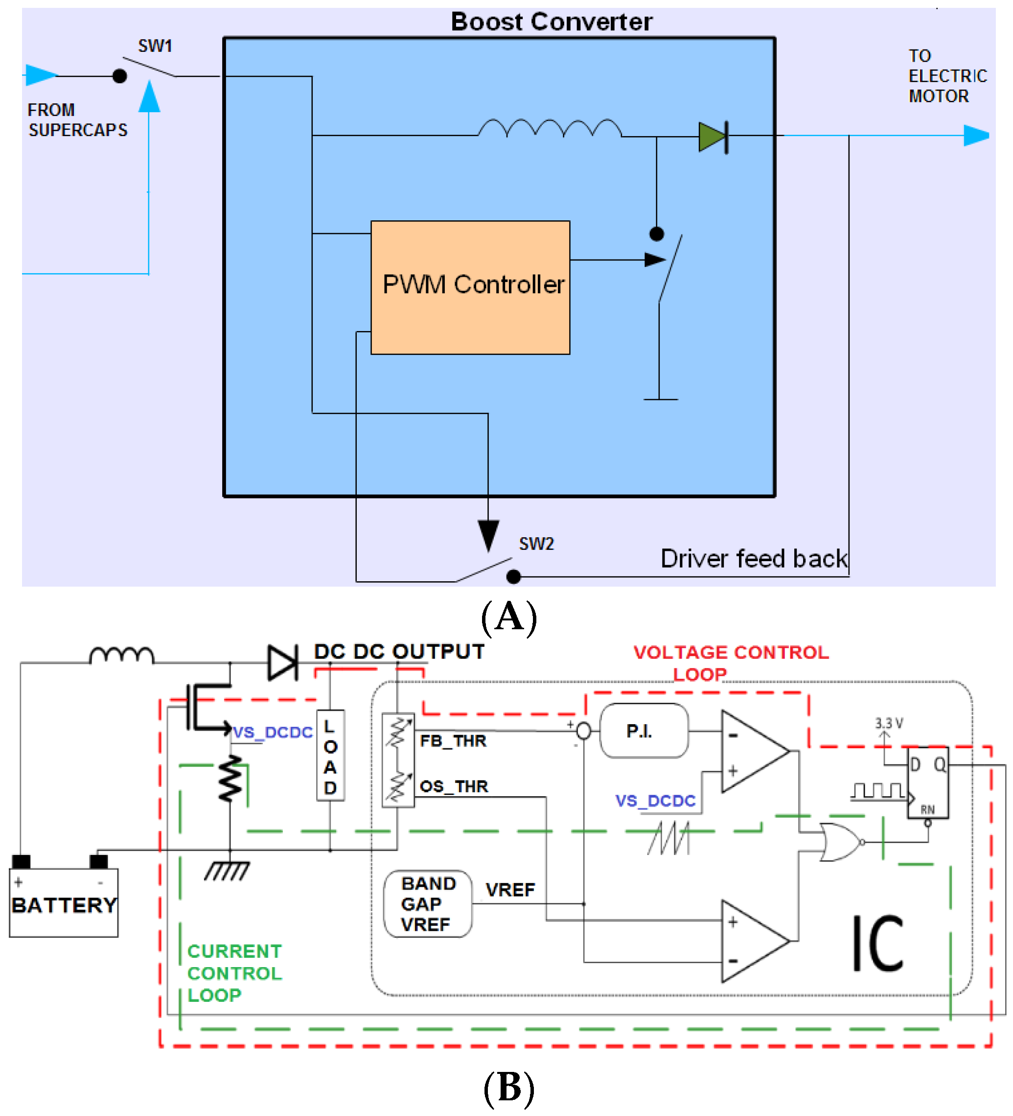
All things considered, we chose supercapacitors as storage devices in our application because of the larger temperature range and the high power density needed, but also aimed for an integration in the same board with the ACU. The proposed energy backup system includes four 3-V, 25-F electric double-layer capacitors (EDLC) connected in series plus an on-board boost converter. An energy backup of 450 J is provided, which is sufficient for multiple emergency actuations, meeting the requirements of tens to hundreds of joules. This solution provides an unregulated nominal voltage of 12 V, dropping to a value higher than 6 V in case the supercapacitors are discharged but still within the degradation limit accepted by the diagnostic check. Below 6 V, the energy backup subsystem is judged to be not working by an integrated diagnostic circuitry. An integrated buck/boost converter, sketched in
Figure 2 when used in boost configuration mode, with programmable output voltage value ensures all required outputs from a few volts up to tens of volts.
The microcontroller of the ACU properly drives as open the converter switch SW1 and the feedback switch SW2 of
Figure 2A, when the main battery voltage is present. The boost converter is thus normally off, the supercapacitors maintain their backup energy, and even the resistors of the converter feedback are disconnected to save power. When the main battery fails, the microcontroller is supplied by a partition of the supercapacitors in series (partition of the 12 V), and the switches SW1 and SW2 are turned on so that the actuator is supplied by the supercapacitors. The switches SW1 and SW2 are integrated in the same actuator PCB board and are realized with low-resistance discrete MOS (Metal Oxide Semiconductor transistor) to maximize power efficiency. The main inductor also has a series resistance of a few milliohms. It should be noted that the converter (
Figure 2B) integrates both voltage mode and current mode controls. The programmability of the output voltage (
DCDC output in
Figure 2B) is ensured by changing the feedback reference threshold (
FB-THR in
Figure 2B) through a digitally controlled resistive-based partition circuit. The same partitioning circuit is also used to generate a proper control threshold (
OS_THR in
Figure 2B) used to avoid overvoltage phenomena.
4. Energy Backup Devices Durability and Temperature Assessment
The characterization of the supercapacitors used for the backup energy unit was carried out with an experimental setup consisting of a thermal chamber Binder MK53 for temperature-controlled tests, plus a Keithley 2420 Source-Meter Unit to evaluate capacitance value, series resistance, the leakage resistance, and how they degrade with the lifecycle at different operating conditions. Let us define C as the capacitance of the supercapacitor, Vmax the maximum allowed voltage, Vref = 0.9 × Vmax = 2.7 V, and Iref = C × Vref/30 = 2.25 A. The following tests were carried out.
Constant-current charge/discharge capacitance test: The device is charged at 23 °C for 3 cycles at a constant current Itest = Iref/4 up to Vref, and then it is kept at this constant voltage for 10 ms and is then completely discharged at constant current Iref/4; the 3-cycle test is repeated with current values of Iref/2 and 2Iref. The capacitance of the supercapacitors in charge and in discharge modes is calculated as C = Itest × Ttest/Vref.
Constant-current ESR test: The equivalent series resistance (ESR) of supercapacitor has a visible effect during the above-described charge/discharge tests at the start of the discharge phase, where the current step determines a voltage drop. Dividing the voltage drop by the constant discharge current allows for the calculation of the ESR value.
Leakage test: The supercapacitor loses charge because of the auto-discharge phenomenon, which can be modeled as a parallel time-variant leakage resistance Rp. The supercapacitor is charged from 0 to Vref at 23 °C and is kept at such a voltage value for 3 h. The capacitor current Ileak needed to hold the constant voltage value while this time interval represents the leakage current. The parallel resistance Rp is the ratio Vref/Ileak, and it is calculated after 30 min, 1, 2 and 3 h. This test is usually repeated at different temperatures and for different durations.
Technology spreading test: The leakage, ESR, and capacitance tests are repeated using different samples of the same device to evaluate the technology spreading.
Thermal test: The above tests are also repeated on the same supercapacitor at different temperatures to determine the temperature dependence of capacitance, ESR, and leakage.
Durability-temperature test: After 10 charge/discharge training cycles at 1 A, the supercapacitor is characterized at 23 °C using the above-described procedures. This is the starting point of a durability test. A loop of 52 cycles is repeated. The loop consists of a first charge from Vmax/2 to 0.9 Vmax; 50 charge/slow discharge cycles between 90% and 80% of Vmax with a charging current of Iref/20 and a discharge current of 10 mA follow. One last charge/fast discharge cycle between 90% and 70% of Vmax with a charge current of Iref/20 and a discharge of Iref/2 completes the loop. The entire loop is then repeated 60 times. Such tests are repeated at −40, −30, 80 and 100 °C for more than 10,000 cycles (52 cycles × 60 loops × 4 temperatures = 12,480 cycles). The basic ESR-capacitance-leakage characterization at 23 °C is carried out after each temperature value to analyze degradations caused by the durability test.
High temperature test: This consists of a 15-min test at 130 °C followed by 60 min at 110 °C. The supercapacitor is characterized at 23 °C (ESR, leakage, capacitance) before and after the high temperature test to evaluate possible performance degradations due to high temperature transient cycles. All the thermal tests are carried out in a Binder MK53 thermal chamber. During high temperature transients, the operation of the device is not required, only that it is not damaged or degraded, i.e., when the temperature transient ends, the device should recover its functionality.
ESD test: The components forming the proposed ACU have ben also subject to ESD tests according to the HBM (human-body model), which aims to simulate ESD events due to the interaction of the device with the human body. A 100-pF capacitor (pre-charged at thousands of volts, a minimum of 2 kV is required for AEC-Q100 automotive qualification) is discharged on a pin of the device under test through a 1.5-kΩ series resistor. The device is tested before and after the ESD stress. By comparing the results, it was verified that no shifts of the parameters of the energy backup unit occurred during the stress.
All the above-described tests were applied to several EDLC supercapacitors from different vendors, with a nominal voltage from 2 to 3 V and a capacitance ranging from 10 to 50 F. We report here the main results obtained for the selected device, a 3-V, 25-F EDLC, which demonstrates the suitability of the supercapacitor to ensure an energy backup of 450 J (4 supercapacitors in series).
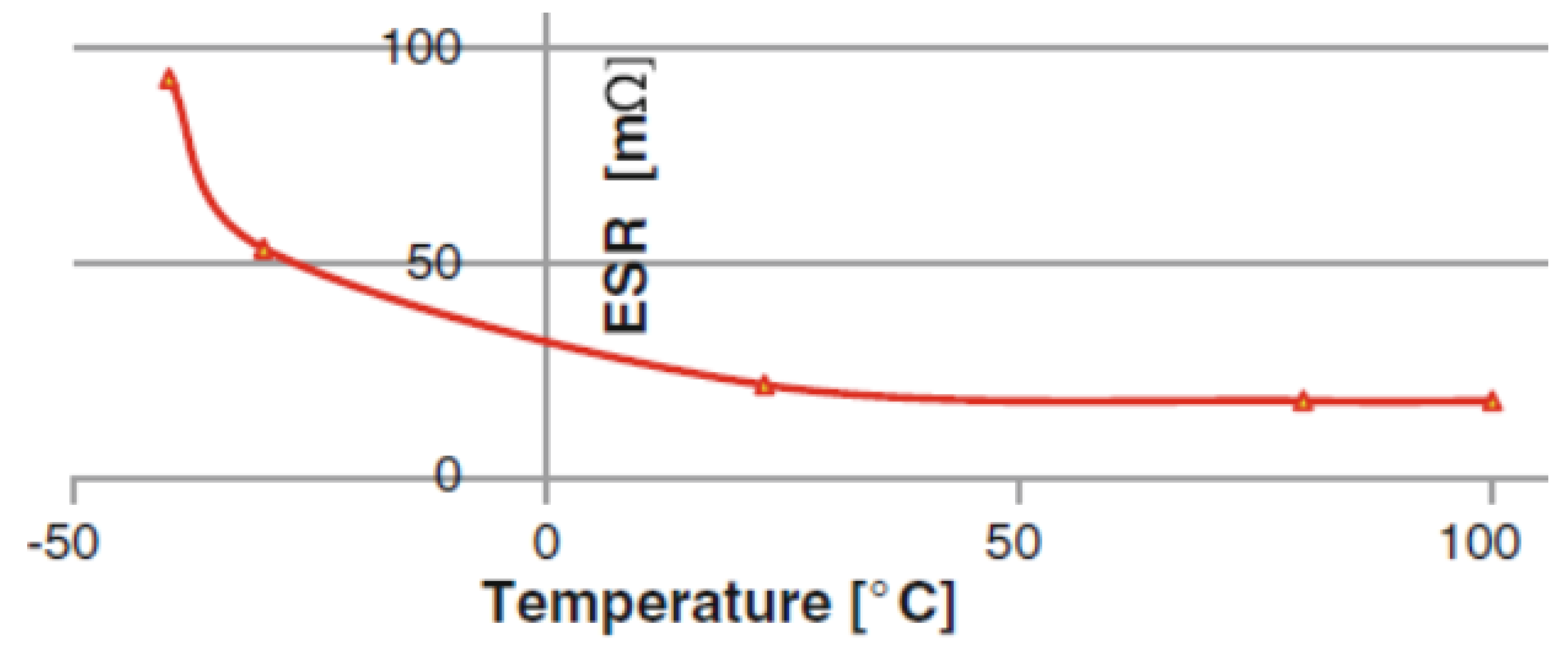
Figure 3 shows the measured ESR as a function of temperature, in a range from −40 to 100 °C. The series resistance increases when the temperature decreases, but it is always well below 100 mΩ.
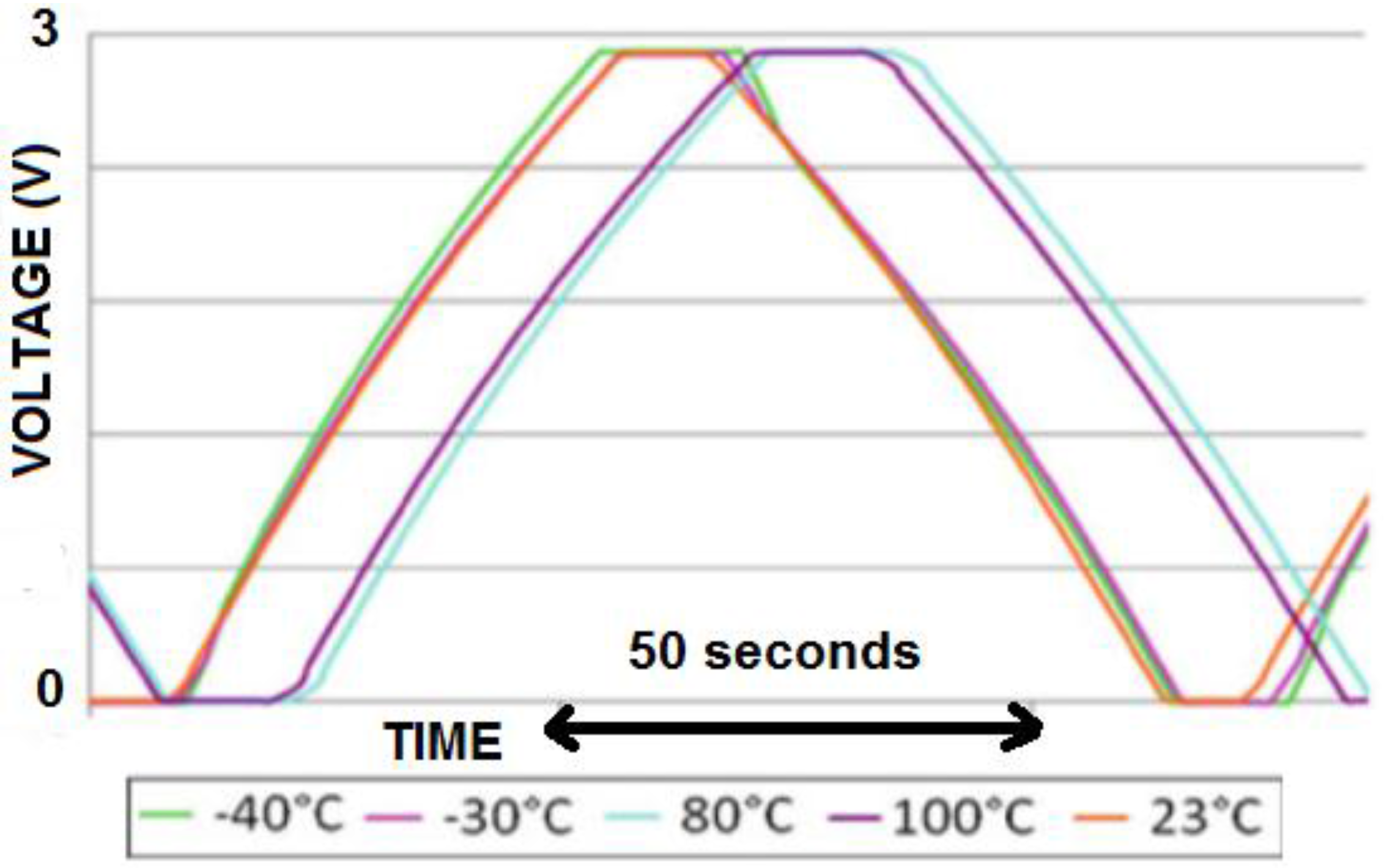
Figure 4 shows charge and discharge transients as a function of temperature. Since the capacitance value changes as a function of temperature, the voltage slope of the charge/discharge test changes in its turn. While the ESR behavior is monotonic with the temperature, and there is a large variation at low temperatures in
Figure 3, the voltage slope value in
Figure 4 is instead weakly dependent on the temperature between −40 °C and room temperature. A difference in the time slope in
Figure 4 and hence in the capacitance is noticeable when going from room temperature to 100 °C. The slope and hence the capacitance increases with the temperature when going from −40 to 80 °C. Instead, the capacitance decreases going from 80 to 100 °C. In fact, the capacitance is composed of a fixed part C0 that increases with the temperature and a voltage dependent part, Cv(V), that instead decreases when temperature increases. The time-variant parallel resistance Rp extracted from the leakage test is in the order of some kΩ after 30 min and rises up to hundreds of kΩ after 3 h. As far as the technology spreading is concerned, repeating the tests on different samples of the same supercapacitor gives a spreading of the results limited to a low percentage, showing good repeatability of the device characteristics. A limited mismatch of the samples makes the equalization problem that arises when multiple units are connected in series negligible. The high temperature transient up to 130 °C does not affect the supercapacitor performance since the ESR and the capacitance values, measured at ambient temperature after the high thermal cycle, show that the capacitance change is less than 5%, and the ESR is still around 20 mΩ.
According to the results of the durability testing campaign, after more than 10,000 charge/discharge cycles at different temperature values, from −40 to 100 °C, an increase limited to less than 3% was observed for the series resistance. For the capacitance value, an increase of less than 10% was observed. These values are well acceptable for the target applications. They demonstrate the suitability of the supercapacitors as energy backup sources, even after thousands of operating cycles. A major effect is instead noticed on the leakage current: The 3-h leakage value increases from 2 to 50 µA after the durability test. This means that, after more than 10,000 cycles, the investigated supercapacitors are completely autodischarged in about 106 s, i.e., around 11 days, if they are not recharged. This is not a problem when the main battery is working and it is continuously charging the supercapacitors (the boost converter is off). Should a main battery failure occur, the supercapacitors backup energy source is needed to actuate the servomotors of the robotized arm, the electric motor of the E-latch, or the voice coil actuator of the gearbox; hence, 11 days before the complete autodischarge is still a long time considering the typical target applications.
5. Application of the Proposed ACU to Biomedical Robotics Actuation
As an example of how this can be applied, the mechatronic ACU can be used for the control of a servomotor for rehabilitation. A wearable prosthetic device, using an anthropomorphic Lynxmotion AL5B robot [
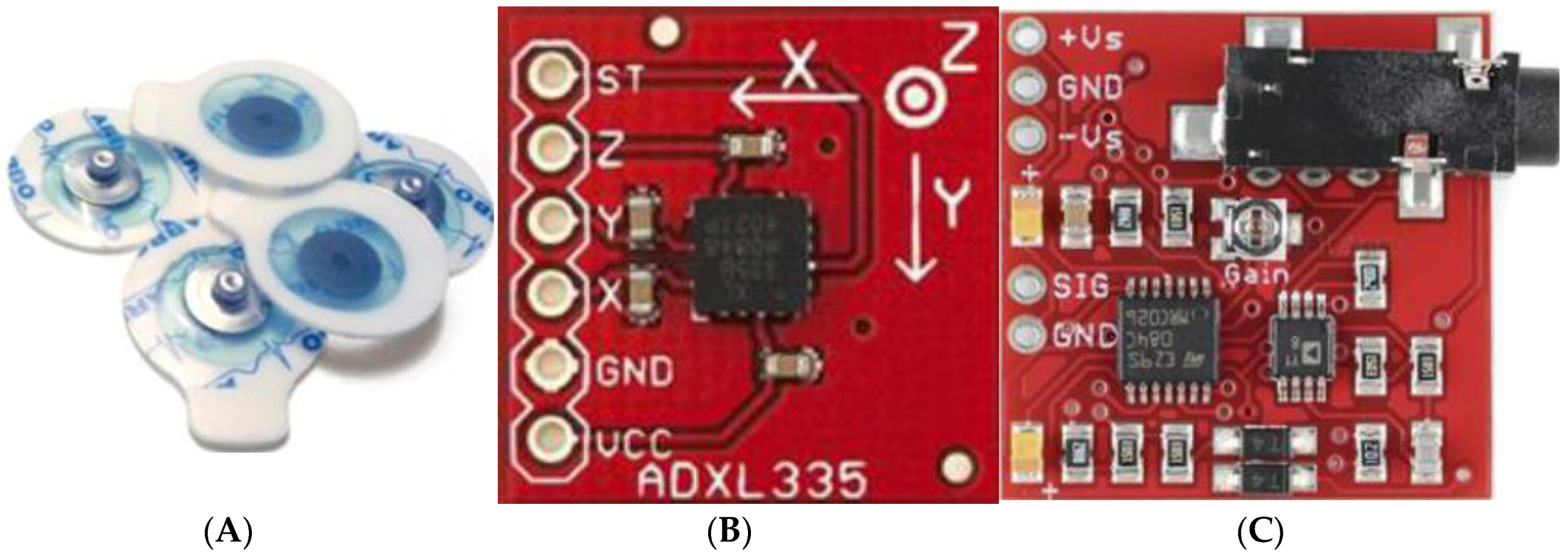
5], can give back the possibility of grasping to people with arm impairments. The mechanical elements that make up the structure of the anthropomorphic robot are labeled with names that evoke the human nature itself: Body (axe 1), Shoulder (axe 2), Arm (axe 3), Elbow (axe 4), Wrist (axe 5), and Hand (Clamp). This robot has 5 degrees of freedom, and it is formed only by revolving joints, actuated by 5 servomotors, plus a supporting structure, which ensures stability, and a terminal body consisting of a gripper. The control signal pilots the servomotors according to a PWM strategy. The pulse duration determines the position of the servo shaft, lasting 1 to 2 ms per 20-ms cycle. The width of the positive part of the impulse determines the position of the servomotor: 1 ms corresponds to the axis of the engine rotated in one direction; 2 ms corresponds to fully rotated axis in the opposite direction; and all the intermediate positions are possible by regulating the duty cycle. This biomedical system is controlled through EMG signals and through acceleration sensors placed on the arm of the elderly/disabled people. From the sensor acquired arm acceleration, and its integration in the digital domain, the position of the arm in the space is reconstructed. The accelerator sensor is a 3-axis Analog Devices ADXL335 with a sensitivity of 0.3 g/V. The EMG signal, acquired through Ag/AgCl electrodes (with a diameter of 24 mm) (
Figure 5) is used to detect the patient’s desire to do, or not do, an action. The electrodes are placed according to a bipolar mode, which is carried out with two active electrodes positioned in correspondence with the examined muscle and a third on a neutral reference point. The distance between the two electrodes is 2 cm in this work. Bipolar recording provides better spatial resolution and rejection against noise, but, in the case of small muscles, it is difficult to use, being less selective than monopolar and requesting a bigger area for the placement of electrodes.
The interference pattern of the EMG signal has a highly random nature and is strongly dependent on a series of variables often difficult to control, which are responsible for a substantial difference of the signal across different trials. In addition, all the layers of an adipose tissue that interpose between the signal source and the electrodes provide a low-pass filter effect in the frequency domain. However, in first approximation, the detected signal is characterized by a base-line of zero mean value during the resting phase, with maximum widths of around 10 μV, and a trend to burst during the contraction phase, with maximum peak-to-peak voltage of 10 mV. The usable signal energy is limited to frequencies between 0 and 500 Hz [
35,
36], with useful energy in the range 30–100 Hz. Usable signals are those whose energy is above the noise level. To eliminate these artifacts of the signal, it is useful to employ a differential configuration for detection. The differential amplifier (an AD 8221 instrumentation amplifier is used) detects the potential by two electrodes, which are then subtracted and the resulting difference is amplified. The signal is then rectified (with active rectifier) and filtered. As the dominant energy of the EMG signal is located between 30 and 100 Hz, a band pass filter in the range of 10–500 Hz is then applied and, according to Shannon theorem, the signal is then digitized with a frequency of 1 kHz.
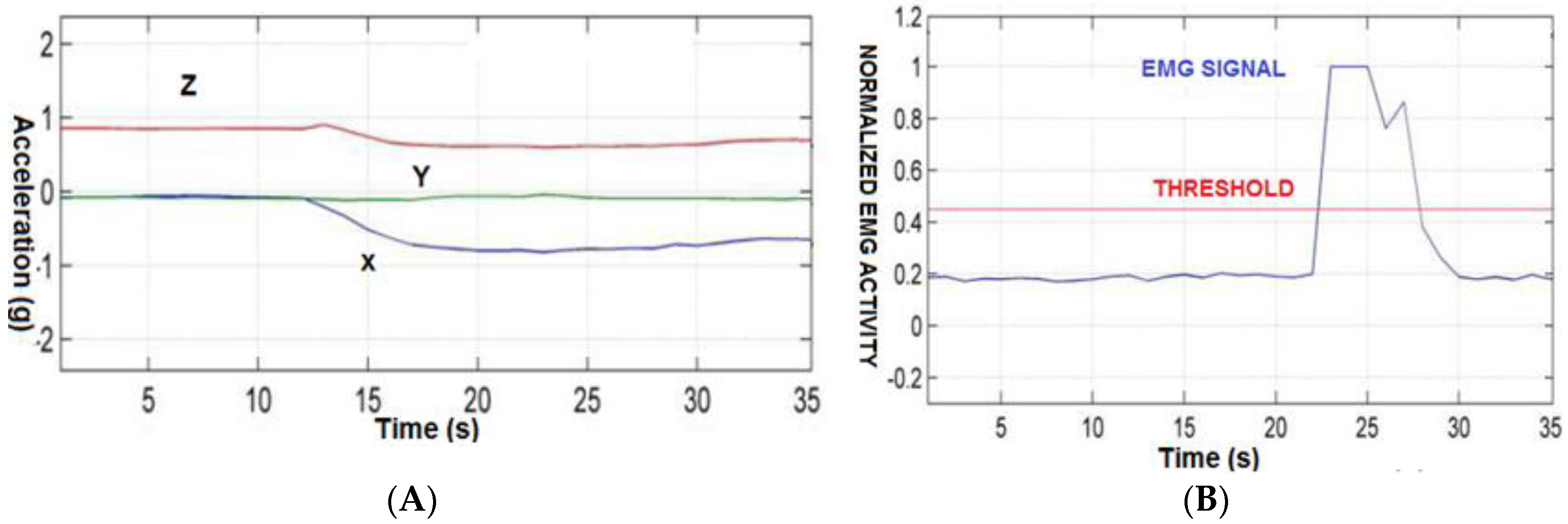
Figure 6A shows, an example, the response inclination in the direction of negative x of the ADXL335.
Figure 6B shows, as an example, the signal of muscle contraction over the threshold. Once reconstructed, the arm position and the desire to do, or not do, an action, with the platform in
Figure 1 based on embedded 32-bit ARM Cortex processor, we provide the proper PWM signal to implement the action to servomotors each having a peak power of 100 W. The required energy in the case of battery failure to complete the action is 100 W per 20 ms for the 5 servomotors for a total budget of 10 J. The 450-J energy backup system would ensure more than 40 actuations before entering into safety mode. The required voltage at which the converter is programmed is 9 V.
6. Application to Automotive Electric Actuation
To prove the configurability of the proposed solution, the ACU in
Section 2 with the energy backup system of
Section 3 and
Section 4 can be also used for electric actuation of two key car subsystems:
automatic gearbox control, exploiting a voice coil actuator.
the actuation of an on/off electric motor for door opening/closure control (E-latch).
The voice coil actuator for robotized gearbox is a 28-V load with a peak power of 350 W. In case of emergency, the energy backup unit should ensure at least 10 gear shifts, each of them requiring roughly 300 W for 40 ms, for a total energy budget of 12 J. Feedback from the voice coil actuator operation is obtained by measuring the flowing current in the actuator through hall sensors.
Figure 7 shows the functionality of the gearbox control and actuation system, which has been described elsewhere [
7], when mapped on the ACU proposed in this work in
Figure 1. While the implementing platform has been realized through multiple PCB boards and without any countermeasure against battery failure [
7], in this work, the same control functionality can be mapped in the new ACU, which is embedded in a single PCB board and with an increased reliability thanks to the new energy backup subsystem. The gear sensor, the RPM (revolutions per minute) of the engine, and the current feedbacks of the voice coil actuator (VCA in
Figure 7) are acquired directly through the 10-b A/D converter in
Figure 1. Flipper paddles, push buttons, and other parts of the dashboard are connected through the GPIO of the scheme in
Figure 1.
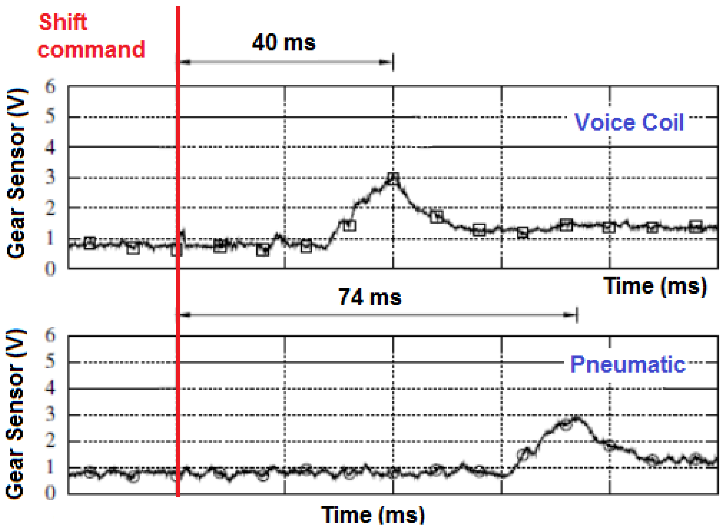
Figure 8 shows that the time needed for a gear shift with electric actuation, based on voice coil actuator, was reduced by roughly 50% (40 ms instead of 74 ms) when compared to a currently used pneumatic actuation system. These data were acquired in a real-world test with the ET-1 Formula SAE race car. The saved gear shift time can even be a key feature for premium sport cars.
Another example of how this can be applied, demonstrating the flexibility and programmability of the new ACU architecture, is the controlling of the opening and closing, through an electric motor, of the latch of a car’s door system. This application was developed in collaboration with Magna Closures, patented in another work [
12], in the framework of the AMDS (Advanced Mechatronic Door System) FESR project (EU commission and Tuscany Region). Digital data can be exchanged with the vehicle management unit (VMU) or the dashboard to receive commands or to transmit diagnostic flags through a serial bus, LIN or low-speed CAN connection being the most frequently used in automotive applications. The required energy sufficient for 10 door releases in the case of main battery failure is about 100 J. Indeed each release of the door's latch typically requires 10 J. The E-Latch is divided in two main units: the Latch core and the vehicle networking bridge towards the LIN domain. The control unit can acquire, in the digital domain through proper position and current sensors, connected to the A/D converter input channels of
Figure 1, the following data from the external environment: the status of the internal and external handles, the status of the electric motor actuating the latch (open, closed), and the actual value of the battery voltage. Proper commands are received in the digital domain through LIN (e.g., if the car key is ON or not, if lock or special anti-theft, or if child lock commands are required by the user). By processing the above data in the CPU core of
Figure 1, a PWM control signal is generated to drive the motor latch, and status/diagnostic flags are transmitted back through the LIN network to the dashboard or to the VMU. For example,
Figure 9 shows an experimental test of a latch door release showing the motor torque as a function of time (time division is 100 ms/div). The test in
Figure 9 is repeated with success in different operating conditions of the energy backup source (fully charged at 12 V and partially discharged at 9 V) and temperature (23 and 80 °C), demonstrating the reliability of the electric actuation in various conditions. The proposed ACU can be used also to control the electric motor of a car’s window lifter, since it is characterized by functionalities similar to the E-latch.


